EP2801904B1 - Appareil électronique et procédé de contrôle de celui-ci - Google Patents
Appareil électronique et procédé de contrôle de celui-ci Download PDFInfo
- Publication number
- EP2801904B1 EP2801904B1 EP14153178.0A EP14153178A EP2801904B1 EP 2801904 B1 EP2801904 B1 EP 2801904B1 EP 14153178 A EP14153178 A EP 14153178A EP 2801904 B1 EP2801904 B1 EP 2801904B1
- Authority
- EP
- European Patent Office
- Prior art keywords
- electronic apparatus
- sound data
- bluetooth
- sound
- speaker
- Prior art date
- Legal status (The legal status is an assumption and is not a legal conclusion. Google has not performed a legal analysis and makes no representation as to the accuracy of the status listed.)
- Active
Links
- 238000000034 method Methods 0.000 title claims description 45
- 238000004891 communication Methods 0.000 claims description 36
- 230000006870 function Effects 0.000 description 6
- 230000004044 response Effects 0.000 description 3
- 238000010586 diagram Methods 0.000 description 2
- 238000012905 input function Methods 0.000 description 2
- 230000001419 dependent effect Effects 0.000 description 1
- 238000005516 engineering process Methods 0.000 description 1
- 239000004973 liquid crystal related substance Substances 0.000 description 1
- 238000003032 molecular docking Methods 0.000 description 1
- 238000003672 processing method Methods 0.000 description 1
- 239000004065 semiconductor Substances 0.000 description 1
- 239000010454 slate Substances 0.000 description 1
Images


Classifications
-
- G—PHYSICS
- G06—COMPUTING; CALCULATING OR COUNTING
- G06F—ELECTRIC DIGITAL DATA PROCESSING
- G06F3/00—Input arrangements for transferring data to be processed into a form capable of being handled by the computer; Output arrangements for transferring data from processing unit to output unit, e.g. interface arrangements
- G06F3/16—Sound input; Sound output
-
- G—PHYSICS
- G06—COMPUTING; CALCULATING OR COUNTING
- G06F—ELECTRIC DIGITAL DATA PROCESSING
- G06F1/00—Details not covered by groups G06F3/00 - G06F13/00 and G06F21/00
- G06F1/16—Constructional details or arrangements
- G06F1/1613—Constructional details or arrangements for portable computers
- G06F1/1633—Constructional details or arrangements of portable computers not specific to the type of enclosures covered by groups G06F1/1615 - G06F1/1626
- G06F1/1684—Constructional details or arrangements related to integrated I/O peripherals not covered by groups G06F1/1635 - G06F1/1675
- G06F1/1698—Constructional details or arrangements related to integrated I/O peripherals not covered by groups G06F1/1635 - G06F1/1675 the I/O peripheral being a sending/receiving arrangement to establish a cordless communication link, e.g. radio or infrared link, integrated cellular phone
-
- H—ELECTRICITY
- H04—ELECTRIC COMMUNICATION TECHNIQUE
- H04R—LOUDSPEAKERS, MICROPHONES, GRAMOPHONE PICK-UPS OR LIKE ACOUSTIC ELECTROMECHANICAL TRANSDUCERS; DEAF-AID SETS; PUBLIC ADDRESS SYSTEMS
- H04R3/00—Circuits for transducers, loudspeakers or microphones
-
- G—PHYSICS
- G06—COMPUTING; CALCULATING OR COUNTING
- G06F—ELECTRIC DIGITAL DATA PROCESSING
- G06F1/00—Details not covered by groups G06F3/00 - G06F13/00 and G06F21/00
- G06F1/26—Power supply means, e.g. regulation thereof
- G06F1/32—Means for saving power
- G06F1/3203—Power management, i.e. event-based initiation of a power-saving mode
- G06F1/3234—Power saving characterised by the action undertaken
- G06F1/325—Power saving in peripheral device
-
- G—PHYSICS
- G06—COMPUTING; CALCULATING OR COUNTING
- G06F—ELECTRIC DIGITAL DATA PROCESSING
- G06F1/00—Details not covered by groups G06F3/00 - G06F13/00 and G06F21/00
- G06F1/26—Power supply means, e.g. regulation thereof
- G06F1/32—Means for saving power
- G06F1/3203—Power management, i.e. event-based initiation of a power-saving mode
- G06F1/3234—Power saving characterised by the action undertaken
- G06F1/3287—Power saving characterised by the action undertaken by switching off individual functional units in the computer system
-
- G—PHYSICS
- G06—COMPUTING; CALCULATING OR COUNTING
- G06F—ELECTRIC DIGITAL DATA PROCESSING
- G06F13/00—Interconnection of, or transfer of information or other signals between, memories, input/output devices or central processing units
- G06F13/14—Handling requests for interconnection or transfer
-
- G—PHYSICS
- G06—COMPUTING; CALCULATING OR COUNTING
- G06F—ELECTRIC DIGITAL DATA PROCESSING
- G06F3/00—Input arrangements for transferring data to be processed into a form capable of being handled by the computer; Output arrangements for transferring data from processing unit to output unit, e.g. interface arrangements
- G06F3/16—Sound input; Sound output
- G06F3/165—Management of the audio stream, e.g. setting of volume, audio stream path
-
- H04B5/48—
-
- H—ELECTRICITY
- H04—ELECTRIC COMMUNICATION TECHNIQUE
- H04M—TELEPHONIC COMMUNICATION
- H04M1/00—Substation equipment, e.g. for use by subscribers
- H04M1/72—Mobile telephones; Cordless telephones, i.e. devices for establishing wireless links to base stations without route selection
- H04M1/724—User interfaces specially adapted for cordless or mobile telephones
- H04M1/72403—User interfaces specially adapted for cordless or mobile telephones with means for local support of applications that increase the functionality
- H04M1/72409—User interfaces specially adapted for cordless or mobile telephones with means for local support of applications that increase the functionality by interfacing with external accessories
- H04M1/72412—User interfaces specially adapted for cordless or mobile telephones with means for local support of applications that increase the functionality by interfacing with external accessories using two-way short-range wireless interfaces
-
- H—ELECTRICITY
- H04—ELECTRIC COMMUNICATION TECHNIQUE
- H04M—TELEPHONIC COMMUNICATION
- H04M1/00—Substation equipment, e.g. for use by subscribers
- H04M1/72—Mobile telephones; Cordless telephones, i.e. devices for establishing wireless links to base stations without route selection
- H04M1/724—User interfaces specially adapted for cordless or mobile telephones
- H04M1/72403—User interfaces specially adapted for cordless or mobile telephones with means for local support of applications that increase the functionality
- H04M1/72442—User interfaces specially adapted for cordless or mobile telephones with means for local support of applications that increase the functionality for playing music files
-
- H—ELECTRICITY
- H04—ELECTRIC COMMUNICATION TECHNIQUE
- H04M—TELEPHONIC COMMUNICATION
- H04M2250/00—Details of telephonic subscriber devices
- H04M2250/02—Details of telephonic subscriber devices including a Bluetooth interface
-
- Y—GENERAL TAGGING OF NEW TECHNOLOGICAL DEVELOPMENTS; GENERAL TAGGING OF CROSS-SECTIONAL TECHNOLOGIES SPANNING OVER SEVERAL SECTIONS OF THE IPC; TECHNICAL SUBJECTS COVERED BY FORMER USPC CROSS-REFERENCE ART COLLECTIONS [XRACs] AND DIGESTS
- Y02—TECHNOLOGIES OR APPLICATIONS FOR MITIGATION OR ADAPTATION AGAINST CLIMATE CHANGE
- Y02D—CLIMATE CHANGE MITIGATION TECHNOLOGIES IN INFORMATION AND COMMUNICATION TECHNOLOGIES [ICT], I.E. INFORMATION AND COMMUNICATION TECHNOLOGIES AIMING AT THE REDUCTION OF THEIR OWN ENERGY USE
- Y02D10/00—Energy efficient computing, e.g. low power processors, power management or thermal management
Definitions
- the present invention relates to an electronic apparatus, and more particularly, to an electronic apparatus capable of outputting sound transmitted thereto using a Bluetooth method even when the electronic apparatus is not booted.
- a notebook computer refers to a notebook-sized portable computer which may be conveniently carried and used on the move. Recently, a slate personal computer (PC) and a tablet PC, etc., on which a touch screen is mounted and a keyboard is removed to enhance mobility, have been widely used.
- PC personal computer
- tablet PC etc.
- Conventional notebook computers have a high-performance speaker and are capable of performing Bluetooth communication, and thus a user is able to transmit sound data stored in an external apparatus to a notebook computer using a Bluetooth method to listen to the sound data.
- US2011/129104 and US2005/086614 relate to an electronic apparatus for playing received audio data when the electronic apparatus is powered off.
- the present general inventive concept provides an electronic apparatus capable of outputting sound corresponding to sound data transmitted to the electronic apparatus using a Bluetooth method even when the electronic apparatus is not booted. That is, when the electronic apparatus is in a power-off state, the electronic apparatus may both receive sound data from an external apparatus and output the sound data as sound.
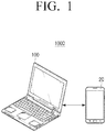
- FIG. 1 is a view illustrating an electronic system according to an exemplary embodiment of the present general inventive concept.
- an electronic system 1000 is composed of an electronic apparatus 100 and an external apparatus 20.
- the electronic apparatus 100 receives an operation instruction from a user, and executes an operation in response to the received operation instruction.
- the electronic apparatus 100 may receive sound data from the external apparatus 20 using the Bluetooth method, and may output the received sound data using an embedded speaker.
- the electronic apparatus 100 may be a PC, a notebook computer, a Portable Multimedia Player (PMP), a cradle of an electronic device, or the like, which operates after booting an operating system.
- a PC may be an all-in-one PC
- a cradle may be a configuration which is capable of extending functions of a notebook computer, a PMP, or any electronic device, by being connected thereto.
- the cradle may be a docking station of a PMP which charges a battery of the PMP while also performing functions of the PMP (i.e., playing sound data). Operations and configurations of the electronic apparatus 100 will be described below in detail with reference to FIG. 2 .
- the external apparatus 20 stores sound source data and transmits sound data corresponding to the stored sound source data to the electronic apparatus 100 using the Bluetooth method.
- the external apparatus 20 may be any one of a PC, a notebook computer, a mobile phone, a smart phone, a PMP, an MP3 player, and the like, so long as it supports Bluetooth communication.
- FIG.2 is a block diagram illustrating a configuration of the electronic apparatus in FIG. 1 .
- the electronic apparatus 100 of the present general inventive concept may include a communication interface 110, a user interface 120, a storage 130, a sound processor 140, a speaker 150, and a controller 160.
- the electronic apparatus 100 includes a plurality of operation modes. According to an operation state of the electronic apparatus 100, the plurality of operation modes may be classified into a normal mode in which the electronic apparatus 100 executes a normal operation using the operating system and a non-booting mode in which the operating system is not loaded on the electronic apparatus 100.
- the normal mode refers to a mode in which the operating system stored in a non-volatile memory is loaded on a volatile memory so that an operation of the electronic apparatus 100 is controlled
- the non-booting mode refers to a mode in which an operation of the electronic apparatus 100 is not controlled by the operating system, for example, a power-off mode, a power saving mode, any other mode than the normal mode, etc.
- the communication interface 110 may be formed to connect the electronic apparatus 100 to an external apparatus, for example external apparatus 20, and may be connected to the external apparatus 20 using not only a Local Area Network (LAN) and an internet network, but also a wireless communication method (e.g., a wireless communication method such as GSM, UMTS, LTE, Bluetooth, WiBRO, etc.).
- LAN Local Area Network
- wireless communication method e.g., a wireless communication method such as GSM, UMTS, LTE, Bluetooth, WiBRO, etc.
- the communication interface 110 may receive sound data from an external apparatus 20.
- the communication interface 110 may include a Bluetooth communicator, and may receive sound data from the external apparatus 20 using the Bluetooth communicator. Further, the communication interface 110 via the Bluetooth communicator may transmit the sound data received from a first external apparatus to a second external apparatus.
- the communication interface 110 may be realized as a single Bluetooth communicator, or may be realized as a plurality of Bluetooth communicators. A case of realizing the communication interface 110 using a single Bluetooth communicator will be described below with reference to FIG. 3 , and a case of realizing the communication interface 110 using a plurality of Bluetooth communicators will be described below with reference to FIG. 4 .
- the present general inventive concept describes data which an apparatus stores as sound source data, and describes data which is exchanged with an external apparatus as sound data for convenience in explanation. However, it should be noted that the sound data and the sound source data may be the same.
- the communication interface 110 may transmit/receive sound data to/from an external apparatus 20.
- the communication interface 110 may transmit and receive different sound data.
- the communication interface 110 may receive sound data transmitted from a first external apparatus 20 using a first Bluetooth communicator, and may transmit sound source data stored in the storage 130, which will be described below, to at least one second external apparatus using a second Bluetooth communicator.
- the user interface 120 may input various commands to perform various functions supported by the electronic apparatus 100, and may display various information provided by the electronic apparatus 100.
- the user interface 120 may be realized as a touch screen where an input function and an output function operate in a single apparatus, as a combination of an input device such as a mouse and a keyboard and an output device such a LCD (Liquid Crystal Display) monitor, or any electronic device or combination of electronic devices capable of interacting with a user to receive an input function and output an output function.
- the user interface 120 may receive a selection of sound source data stored in the storage 130 which will be described below.
- the user interface 120 may display a list of external apparatuses which are connectable using the Bluetooth method, and may input a selection of one of the external apparatuses as an external apparatus to be connected.
- the storage 130 may store a program to operate the electronic apparatus 100.
- the storage 130 may store a program that is a set of various instructions required to operate the electronic apparatus 100.
- the program includes not only an application to provide a certain service but also an operating system to operate the application.
- the storage 130 may store sound source data.
- the sound source data may be sound source data such as a MP3 file, a wav file, or the like, and may be streaming data.
- the storage 130 may be realized as a storage media within the electronic apparatus 100, an external storage media, (e.g., a removable disk including a Universal Serial Bus(USB) memory, a web server based on a network, or the like).
- an external storage media e.g., a removable disk including a Universal Serial Bus(USB) memory, a web server based on a network, or the like.
- the sound processor 140 may process and output received sound data through the speaker 150. To be specific, the sound processor 140 may output sound data received from the communication interface 110 through the speaker 150. The configuration and operation of the sound processor 140 will be described below in detail with reference to FIG. 3 and FIG. 4 .
- the speaker 150 may output sound data provided from the sound processor.
- the present general inventive concept describes that the provided sound data is outputted only through the speaker 150, but the present general inventive concept is not limited thereto.
- the sound data may be outputted through an ear-phone and a speaker which are separable from, and connectable to, the electronic apparatus 100 using a sound output terminal or using a wireless connection (e.g., Bluetooth) in the implementation.
- the controller 160 may control each component within the electronic apparatus 100. To be specific, when a booting instruction is inputted from a user, the controller 160 may perform booting using the operating system stored in the storage 130. In addition, when sound data is transmitted from an external apparatus, for example external apparatus 20, the controller 160 may control the communication interface 110 and the sound processor 140 so that the sound data transmitted from the external apparatus 20 is outputted through the speaker 150.
- the communication interface 110 and the sound processor 140 autonomously output the sound data transmitted from the external apparatus through the speaker 150. That is, the communication interface 110 and the sound processor 140 may output the sound data, transmitted from the external apparatus, through the speaker 150 without receiving outside control from, for example, the controller 160, when the electronic apparatus 100 is not booted.
- the electronic apparatus 100 of the present general inventive concept may output sound data transmitted from the external apparatus 20 through the speaker 150 by the autonomous operations of the communication interface 110 and the sound processor 150 even when the electronic apparatus 100 is not booted.
- the electronic apparatus 100 may output sound data transmitted from the external apparatus 20 through the speaker 150 by the autonomous operations of the communication interface 110 and the sound processor 150 even when the electronic apparatus 100 is not booted.
- the separate audio device or PC such as a notebook computer, an all-in-one PC, or the like.
- implementing the present general inventive concept allows a user to transmit a sound file from an external apparatus to a separate audio device or PC to play and listen to the sound file using the audio device or PC without requiring the user to either directly connect the external device to the audio device or PC or boot the audio device or PC.
- a user may transmit a sound file from the external apparatus to the audio device or PC to play and listen to the sound file using the audio device or PC.
- the electronic apparatus 100 has been shown and described as including the configurations of the controller 160 and the storage 130, but when the electronic apparatus 100 is realized as a cradle, the configurations of the aforementioned controller 160 and the storage 130 may be a configuration of a notebook computer, a PMP, or the like, which is connected to the cradle.
- FIG. 3 is a view illustrating the configurations of the communication interface and the sound processor according to the first example of the present general inventive concept.
- the first example of the present general inventive concept is an implementation example of an electronic apparatus using a single Bluetooth module.
- the controller 160 may have a plurality of sections to be selectively supplied with power and signals to perform a function as described above.
- the communication interface 110 and/or the sound processor 140 may communicate with each other without interference of the controller 160.
- an electronic apparatus 100' may include a switch 111, a Bluetooth communicator 112, a Platform Controller Hub (PCH) 141, an audio codec 143, an audio amplifier 145, and a speaker 150.
- PCH Platform Controller Hub
- the switch 111 may supply power to the Bluetooth communicator 112.
- the switch 111 may supply "AlwaysPWR" to the Bluetooth communicator 112.
- the switch 111 may supply operating power (PWR) to the Bluetooth communicator 112.
- the switch 111 may be omitted in the implementation.
- the AlwaysPWR refers to power which is provided to a configuration for receiving a user's control instruction, and the like, even when the electronic apparatus 100' is not booted
- the PWR refers to power which is provided to each component of the electronic apparatus 100' when the electronic apparatus 100' is in a wake-up process or the operation mode of the electronic apparatus 100' is the normal mode.
- the wake-up process before the normal mode is the normal mode, for convenience in explanation.
- FIG. 3 illustrates the switch 111 as a configuration of supplying power to the Bluetooth communicator 112
- the switch 111 may be a component of a power supply (not depicted) which provides power to each component within the electronic apparatus 100' in the implementation.
- a power supply may supply power to the Bluetooth communicator 112, the PCH 141, and the audio codec 143, and may not supply power to the audio amplifier 145.
- a power supply may supply power only to the Bluetooth communicator 112 and the audio amplifier 145, and may not supply power to the aforementioned PCH 141, the audio codec 143, the controller 160, and the storage 130.
- a power supply may supply power to the Bluetooth communicator 112, the audio amplifier 145, and the speaker 150 only when the electronic apparatus 100' is in the non-booting mode.
- the Bluetooth communicator 112 may be a component of the communication interface 110, and may communicate with at least one external apparatus, for example external apparatus 20, using the Bluetooth method. To be specific, the Bluetooth communicator 112 may receive sound data transmitted using the Bluetooth method from the external apparatus 20.
- the Bluetooth communicator 112 may output the received sound data by varying a processing method to the sound data depending upon an operation mode of the electronic apparatus 100'.
- the Bluetooth communicator 112 may transmit the sound data received from the external apparatus 20 to the sound processor (to be specific, the PCH) using the digital method by control of the controller 160.
- the Bluetooth communicator 112 may be configured to convert the received sound data using an analog method, and transmit the converted analog sound data to the audio amplifier 145 upon receiving the sound data from the external apparatus 20.
- the PCH 141 may be a component of the aforementioned sound processor 140, and may transmit digital sound data outputted from the Bluetooth communicator 112 to the audio codec 143.
- the audio codec 143 may be a component of the aforementioned sound processor 140, may receive digital sound data outputted from the Bluetooth communicator 112 through the PCH 141, may decode the received sound data, and may output the decoded sound data through the speaker 150. Technologies regarding an audio codec are common knowledge, and thus the description for the audio codec 143 will be omitted.
- the audio amplifier 145 may be a component of the aforementioned sound processor 140, may amplify analog sound data outputted from the Bluetooth communicator 112, and may output the amplified sound data through the speaker 150.
- the audio amplifier 145 may operate only when the electronic apparatus 100' is not booted, and may not operate when the electronic apparatus 100' is booted.
- the electronic apparatus 100' When the operation mode of the electronic apparatus 100' is the normal mode, the electronic apparatus 100' may be controlled by an operating system. At this time, when a request for connection in the Bluetooth method is received from an external apparatus, for example external apparatus 20, the Bluetooth communicator 112 may notify the controller 160 that a request for Bluetooth connection has been received from the external apparatus 20, and the controller 160 may control the user interface 120 to display the request for the Bluetooth connection.
- an external apparatus for example external apparatus 20
- the Bluetooth communicator 112 may notify the controller 160 that a request for Bluetooth connection has been received from the external apparatus 20, and the controller 160 may control the user interface 120 to display the request for the Bluetooth connection.
- the controller 160 may perform authentication of the external apparatus 20 via pre-stored information or a user's selection, and may control the Bluetooth communicator 112 to receive sound data from the authenticated external apparatus 20.
- the controller 160 may control the Bluetooth communicator 112, the PCH 141, and the audio codec 143 so that the received sound data is decoded in the audio codec 143.
- the controller 160 may control the audio codec 143 and the speaker 150 so that the decoded sound data is outputted through the speaker 150.
- the power supply does not supply power to the PCH 141, the audio codec 143, and the controller 160, and supplies power to the Bluetooth communicator 112 and the audio amplifier 145.
- the Bluetooth communicator 112 may operate only in a mode of receiving sound data from an external apparatus, for example external apparatus 20.
- the Bluetooth communicator 112 is paired with the external apparatus 20 by a request of the external apparatus 20, and receives sound data from the paired external apparatus 20. At this time, the Bluetooth communicator 112 decodes the received sound data and outputs the analog sound data to the audio amplifier 145. The audio amplifier 145 receives the analog sound data and then amplifies and outputs the received analog sound data through the speaker 150.
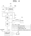
- FIG. 4 is a view illustrating the configurations of the communication interface 110 and the sound processor 140 according to a second exemplary embodiment of the present general inventive concept.
- the second exemplary embodiment of the present general inventive concept is an implementation example of an electronic apparatus using two Bluetooth modules.
- an electronic apparatus 100" is composed of a switch 111', a first Bluetooth communicator 112-1, a second Bluetooth communicator 112-2, the PCH 141, the audio codec 143, the audio amplifier 145, and the speaker 150.
- the switch 111' may selectively output sound data transmitted from the audio codec 143 or the audio amplifier 145 through the speaker 150. Meanwhile, when the operation mode of the electronic apparatus 100" is the non-booting mode, the switch 111' transmits the sound data transmitted from the audio amplifier 145 to the speaker 150, and when the operation mode of the electronic apparatus 100" is the normal mode, the switch 111' selectively outputs the sound data transmitted from the audio codec 143 or the audio amplifier 145 to the speaker 150 via control of the controller 160.
- the first Bluetooth communicator 112-1 may exchange data with an external apparatus, for example external apparatus 20, using a digital method.
- the first Bluetooth communicator 112-1 may operate when the operation mode of the electronic apparatus 100" is the normal mode, and when sound data is received from the external apparatus 20, the first Bluetooth communicator 112-1 may output the received sound data to the PCH 141 using the digital method. Meanwhile, when the operation mode of the electronic apparatus 100" is the non-booting mode, the first Bluetooth communicator 112-1 may not operate since no power is supplied thereto.
- the PCH 141 may be a component of the aforementioned sound processor 140, and may transmit the digital sound data outputted from the first Bluetooth communicator 112-1 to the audio codec 143.
- the PCH 141 may control an operation of the switch 111'.
- the PCH 141 may control an operation of the switch 111'.
- the PCH 141 may control the switch 111' so that an output signal of the audio amplifier 145 is transmitted to the speaker 150.
- the PCH 141 may control the switch 111' so that the output signal of the audio codec 143 is transmitted to the speaker 150.
- the audio codec 143 may be a component of the aforementioned sound processor 140, may receive digital sound data outputted from the first Bluetooth communicator 112-1 through the PCH 141, and may decode and output the received sound data through the speaker 150.
- the second Bluetooth communicator 112-2 may receive sound data from an external apparatus, for example, external apparatus 20, using the Bluetooth method. In addition, when sound data is received from the external apparatus 20, the second Bluetooth communicator 112-2 may convert the received sound data using an analog method, and may transmit the converted analog sound data to the audio amplifier 145.
- the second Bluetooth communicator 112-2 may be a receive-only Bluetooth communication module which is configured to receive data only from an external apparatus, for example external apparatus 20.
- the audio amplifier 145 may be a component of the aforementioned sound processor 140, may amplify and output analog sound data outputted from the second Bluetooth communicator 112-2 through the speaker 150.
- the electronic apparatus 100" When the operation mode of the electronic apparatus 100" is the normal mode, the electronic apparatus 100" is controlled by an operating system. At this time, when a request for connection in the Bluetooth method is received from an external apparatus, for example external apparatus 20, the first Bluetooth communicator 112-1 or the second Bluetooth communicator 112-2 may notify the controller 160 that a request for Bluetooth connection of the external apparatus 20 has been received, and the controller 160 may control the user interface 120 to display the request for the Bluetooth connection.
- an external apparatus for example external apparatus 20
- the first Bluetooth communicator 112-1 or the second Bluetooth communicator 112-2 may notify the controller 160 that a request for Bluetooth connection of the external apparatus 20 has been received, and the controller 160 may control the user interface 120 to display the request for the Bluetooth connection.
- the controller 160 may perform authentication of the external apparatus 20 via pre-stored information or a user's selection, and may decide which Bluetooth communicator will receive sound data from the authenticated external apparatus. Such decision may be performed by a user's selection, and may be set to preferentially connect the second Bluetooth communicator 112-2.
- the controller 160 may control the selected Bluetooth communicator so that the selected Bluetooth communicator receives sound data.
- the second Bluetooth communicator 112-2 is selected for convenience in explanation.
- the controller 160 may control the second Bluetooth communicator 112-2, the PCH 141, and the audio codec 143 so that the received sound data is decoded in the audio codec 143.
- the controller 160 may control the audio codec 143 and the speaker 150 so that the decoded sound data is outputted through the speaker 150.
- the non-selected Bluetooth communicator may selectively transmit sound source data stored in storage 130 to the external apparatus 20 and/or a different external apparatus (not depicted) upon a user instruction or automatically, depending on user pre-stored settings.
- the power supply does not supply power to the PCH 141, the first Bluetooth communicator 112-1, the audio codec 143, and the controller 160, etc., and supplies power to the second Bluetooth communicator 112-2 and the audio amplifier 145.
- the second Bluetooth communicator 112-2 may operate only in a mode of receiving sound data from an external apparatus, for example external apparatus 20.
- the second Bluetooth communicator 112-2 is paired with the external apparatus 20 by a request of the external apparatus 20, and receives sound data from the paired external apparatus 20. At this time, the second Bluetooth communicator 112-2 decodes the received sound data and outputs analog sound data to the audio amplifier 145.
- the audio amplifier 145 receives the analog sound data and amplifies and outputs the received analog sound data through the speaker 150.
- the PCH 141 is a component of the sound processor 140, but the present general inventive concept is not limited thereto.
- the PCH may be realized as a component of the controller 160 in the implementation.
- the Bluetooth communicator and the sound processor 140 have been shown as separate components, but the present general inventive concept is not limited thereto.
- the Bluetooth communicator and the sound processor 140 may be realized as a single component.
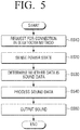
- FIG. 5 is a flow chart illustrating a method of outputting sound according to an exemplary embodiment of the present general inventive concept.
- the electronic apparatus 100 receives a request for connection in the Bluetooth method (S510) from an external apparatus, for example external apparatus 20.
- the electronic apparatus 100 senses the current operation mode (S520) of the electronic apparatus 100, and then determines whether the requested connection is for outputting sound data (S530).
- the electronic apparatus 100 may reject the request of the external apparatus 20.
- the electronic apparatus 100 may accept the request of the external apparatus 20. Meanwhile, if it is determined that the current operation mode is a booting mode and the requested connection is not for outputting sound data, the electronic apparatus 100 may perform an operation by control of the operating system or a user's selection.
- the electronic apparatus 100 processes the received sound data (S540). To be specific, if it is determined that the current operation mode of the electronic apparatus 100 is the non-booting mode, the electronic apparatus 100 processes the sound data using the receive-only Bluetooth communication module (i.e., the Bluetooth communicator 112), and if it is determined that the current operation mode is the booting mode, the electronic apparatus 100 processes the received sound data by the control of the operating system.
- the receive-only Bluetooth communication module i.e., the Bluetooth communicator 112
- the electronic apparatus 100 outputs the processed sound data through the speaker 150 (S550).
- the method of outputting sound may include outputting the received sound data through the speaker 150 using the Bluetooth communicator 112 and the sound processor 140 which autonomously operate even when the electronic apparatus 100 is not booted.
- the sound outputting method in FIG. 5 may be executed on an electronic apparatus having the configuration in FIG. 2 , and may be executed in an electronic apparatus having a different configuration.
- controlling method as specified above may be realized as a program (or an application) including an algorithm executable in a computer, and the program may be provided by being stored in a non-transitory computer readable medium.
- a non-transitory computer readable medium refers to a medium which stores data semi-permanently rather than storing data for a very short time such as a register, a cache, and a memory, and is readable by a device.
- a non-transitory computer readable medium such as a compact disc (CD), a digital versatile disk (DVD), a hard disk, a Blu-ray disk, a universal serial bus (USB), a memory card, and a read-only memory (ROM), or the like.
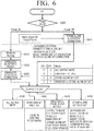
- FIG. 6 is a flow chart illustrating a method of outputting sound when the electronic apparatus 100 includes a plurality of Bluetooth modules according to the present general inventive concept.
- the operation mode of the electronic apparatus 100 is determined (S605).
- the electronic apparatus 100 performs connection with an external apparatus, for example external apparatus 20, using the receive-only Bluetooth module (i.e., the second Bluetooth communicator 112-2) (S610).
- the receive-only Bluetooth module performs a sound process of the received sound data and outputs the sound data through the speaker 150.
- an embedded Bluetooth module i.e., the first Bluetooth communicator 112-1
- S620 the electronic apparatus 100 performs connection with the external apparatus 20 using the embedded Bluetooth module
- a first mode refers to a mode where a speaker does not output any sound
- a second mode refers to a mode where the sound data received through the embedded Bluetooth module (that is, the first Bluetooth communicator 112-1) is outputted through the speaker 150
- a third mode refers to a mode where the sound data received through the receive-only Bluetooth module (that is, the second Bluetooth communicator 112-2) is outputted through the speaker 150
- a fourth mode refers to a mode where the sound data received through the receive-only Bluetooth module is outputted through the speaker 150, and sound source data stored in the electronic apparatus 100 is transmitted to at least one other external apparatus (not depicted) through the embedded Bluetooth communicator.
- the controlling method displays a virtual bezel area when a user's grip is sensed, and does not input a user's touch to the virtual bezel area, and thus may prevent an operation of a touch screen from being executed when the user erroneously inputs a user command in response to gripping/holding the electronic apparatus. That is, the controlling method may display the virtual bezel area in response to sensing a user's grip so that any user command erroneously input over the virtual bezel area by the user while gripping/holding the electronic apparatus will not be executed by the electronic apparatus.
- the controlling method in FIG. 6 may be executed on an electronic apparatus having the configuration in FIG. 2 , and may be executed on an electronic apparatus having a different configuration so long as the electronic apparatus is Bluetooth enabled.
Landscapes
- Engineering & Computer Science (AREA)
- Theoretical Computer Science (AREA)
- General Engineering & Computer Science (AREA)
- Physics & Mathematics (AREA)
- General Physics & Mathematics (AREA)
- Computer Hardware Design (AREA)
- Human Computer Interaction (AREA)
- Computer Networks & Wireless Communication (AREA)
- Signal Processing (AREA)
- Health & Medical Sciences (AREA)
- Audiology, Speech & Language Pathology (AREA)
- General Health & Medical Sciences (AREA)
- Multimedia (AREA)
- Computing Systems (AREA)
- Acoustics & Sound (AREA)
- Telephone Function (AREA)
- Circuit For Audible Band Transducer (AREA)
- Stored Programmes (AREA)
Claims (4)
- Appareil électronique (100"), comportant :un dispositif de stockage (130) agencé pour stocker un système d'exploitation ;un contrôleur (160) agencé pour amorcer l'appareil électronique au moyen du système d'exploitation stocké dans le dispositif de stockage ;un haut-parleur (150) agencé pour émettre du son ;une interface de communication (110) agencée pour recevoir des données sonores en provenance d'un appareil externe ; etun processeur de sons (140) agencé pour traiter et émettre les données sonores reçues par le biais du haut-parleur,dans lequel l'interface de communication, le processeur de sons, et le haut-parleur sont agencés pour fonctionner même quand l'appareil électronique n'est pas amorcé, etcaractérisé en ce que l'interface de communication comporte :un premier communicateur Bluetooth (112-1) agencé pour fonctionner uniquement quand l'appareil électronique est amorcé, et pour échanger des données avec l'appareil externe au moyen d'un procédé Bluetooth et transmettre les données sonores reçues au processeur de sons au moyen d'un procédé numérique ; etun deuxième communicateur Bluetooth (112-2) agencé pour recevoir des données sonores en provenance de l'appareil externe au moyen d'un procédé Bluetooth et transmettre les données sonores reçues au processeur de sons au moyen d'un procédé analogique ;et en ce que le processeur de sons (140) comporte :un amplificateur audio (145) agencé pour amplifier les données sonores transmises par le biais du deuxième communicateur Bluetooth et émettre les données sonores par le biais du haut-parleur ;un codec audio destiné à fonctionner quand l'appareil électronique est amorcé, pour décoder les données sonores transmises au moyen du procédé numérique, et pour émettre les données sonores par le biais du haut-parleur ; etun PCH (Platform Controller Hub - concentrateur contrôleur de plate-forme) (141) agencé pour transmettre les données sonores émises en provenance du premier communicateur Bluetooth au codec audio.
- Appareil selon la revendication 1, dans lequel le premier communicateur Bluetooth fonctionne sous le contrôle du contrôleur, et le deuxième communicateur Bluetooth fonctionne avec ou sans le contrôle du contrôleur.
- Appareil selon la revendication 1, dans lequel l'appareil électronique comporte par ailleurs :
un commutateur (111') agencé pour transmettre de manière sélective les données sonores émises en provenance de l'amplificateur audio ou du codec audio au haut-parleur. - Appareil selon l'une quelconque des revendications 1 à 3, dans lequel le dispositif de stockage stocke des données de sources de sons, et
dans lequel, quand le deuxième communicateur Bluetooth reçoit des données sonores en provenance d'un premier appareil externe, le contrôleur contrôle le deuxième communicateur Bluetooth pour transmettre les données de sources de sons à un deuxième appareil externe.
Applications Claiming Priority (1)
| Application Number | Priority Date | Filing Date | Title |
|---|---|---|---|
| KR1020130052094A KR102121382B1 (ko) | 2013-05-08 | 2013-05-08 | 전자 장치 |
Publications (3)
| Publication Number | Publication Date |
|---|---|
| EP2801904A2 EP2801904A2 (fr) | 2014-11-12 |
| EP2801904A3 EP2801904A3 (fr) | 2016-01-06 |
| EP2801904B1 true EP2801904B1 (fr) | 2019-10-23 |
Family
ID=50064429
Family Applications (1)
| Application Number | Title | Priority Date | Filing Date |
|---|---|---|---|
| EP14153178.0A Active EP2801904B1 (fr) | 2013-05-08 | 2014-01-30 | Appareil électronique et procédé de contrôle de celui-ci |
Country Status (4)
| Country | Link |
|---|---|
| US (1) | US9313571B2 (fr) |
| EP (1) | EP2801904B1 (fr) |
| KR (1) | KR102121382B1 (fr) |
| CN (1) | CN104142809B (fr) |
Families Citing this family (6)
| Publication number | Priority date | Publication date | Assignee | Title |
|---|---|---|---|---|
| US8674959B2 (en) * | 2010-06-28 | 2014-03-18 | Intel Corporation | Dynamic bezel for a mobile device |
| KR102325338B1 (ko) * | 2014-12-05 | 2021-11-11 | 삼성전자주식회사 | 전자 장치, 오디오 장치 및 전원 제어 방법 |
| US10445055B2 (en) * | 2014-12-23 | 2019-10-15 | Lg Electronics Inc. | Mobile terminal, audio output device and audio output system comprising same |
| KR102428712B1 (ko) | 2017-11-24 | 2022-08-03 | 삼성전자주식회사 | 콘텐트를 제공하기 위한 방법 및 이를 지원하는 전자 장치 |
| JP6767015B2 (ja) * | 2018-08-30 | 2020-10-14 | Necプラットフォームズ株式会社 | 電子錠制御装置、電子錠制御システム、電子錠制御装置の制御方法、及び、プログラム |
| WO2024029711A1 (fr) * | 2022-08-04 | 2024-02-08 | 삼성전자 주식회사 | Dispositif audio inclus dans un dispositif électronique et son procédé de commande |
Family Cites Families (14)
| Publication number | Priority date | Publication date | Assignee | Title |
|---|---|---|---|---|
| US6226237B1 (en) * | 1998-03-26 | 2001-05-01 | O2 Micro International Ltd. | Low power CD-ROM player for portable computer |
| US6954804B2 (en) * | 1998-03-26 | 2005-10-11 | Micro, Inc. | Controller for portable electronic devices |
| JP2003523571A (ja) * | 2000-02-15 | 2003-08-05 | オーツー・マイクロ・インク | ポータブル電子機器のオーディオコントローラ |
| TWI221230B (en) * | 2003-10-21 | 2004-09-21 | Compal Electronics Inc | Multi-mode mobile electronic device |
| KR101011384B1 (ko) * | 2004-03-31 | 2011-01-28 | 엘지전자 주식회사 | 오디오 리시버에서의 외부기기 전원 제어장치 |
| US20070282471A1 (en) * | 2006-06-01 | 2007-12-06 | Integrated System Solution Corp. | Bluetooth audio chip with multiple input/output sources |
| US8340721B2 (en) * | 2008-03-19 | 2012-12-25 | Google Inc. | Notebook computer and cell phone assembly |
| JP4881425B2 (ja) * | 2009-11-30 | 2012-02-22 | 株式会社東芝 | 電子機器 |
| JP4772901B2 (ja) * | 2009-11-30 | 2011-09-14 | 株式会社東芝 | 電子機器 |
| KR20110073691A (ko) * | 2009-12-24 | 2011-06-30 | 현대모비스 주식회사 | 차량용 블루투스 모듈에 구비된 마이크 입력부를 이용한 보이스 레코딩 장치 및 그 제어 방법 |
| JP4881428B2 (ja) * | 2009-12-25 | 2012-02-22 | 株式会社東芝 | 電子機器 |
| JP4929346B2 (ja) * | 2009-12-28 | 2012-05-09 | 株式会社東芝 | 電子機器 |
| JP4881447B2 (ja) * | 2010-01-29 | 2012-02-22 | 株式会社東芝 | 電子機器、及び音声信号増幅方法 |
| JP2011233973A (ja) * | 2010-04-23 | 2011-11-17 | Toshiba Corp | 電子機器 |
-
2013
- 2013-05-08 KR KR1020130052094A patent/KR102121382B1/ko active IP Right Grant
-
2014
- 2014-01-30 EP EP14153178.0A patent/EP2801904B1/fr active Active
- 2014-02-25 US US14/188,962 patent/US9313571B2/en active Active
- 2014-03-07 CN CN201410083573.5A patent/CN104142809B/zh active Active
Non-Patent Citations (1)
| Title |
|---|
| None * |
Also Published As
| Publication number | Publication date |
|---|---|
| KR102121382B1 (ko) | 2020-06-10 |
| KR20140132625A (ko) | 2014-11-18 |
| US9313571B2 (en) | 2016-04-12 |
| CN104142809A (zh) | 2014-11-12 |
| US20140334636A1 (en) | 2014-11-13 |
| EP2801904A2 (fr) | 2014-11-12 |
| CN104142809B (zh) | 2018-08-24 |
| EP2801904A3 (fr) | 2016-01-06 |
Similar Documents
| Publication | Publication Date | Title |
|---|---|---|
| EP2801904B1 (fr) | Appareil électronique et procédé de contrôle de celui-ci | |
| JP6131339B2 (ja) | ポータブルコンピューティングデバイスに結合される受入れデバイスの熱ポリシーを管理するためのシステムおよび方法 | |
| KR20120032888A (ko) | 모바일 디바이스의 전력소모 감소 방법 및 장치 | |
| US20140068297A1 (en) | State control method and apparatus and portable terminal | |
| JP2016537749A (ja) | アクセサリーデバイスの電源管理 | |
| US9696779B2 (en) | Integrated circuit, electronic device and operation method thereof | |
| EP2743796A2 (fr) | Appareil électronique, procédé de commande associé et support d'enregistrement lisible par ordinateur | |
| JP6647285B2 (ja) | システムオンチップのサブシステムの外部アクセス検出および回復のためのシステムおよび方法 | |
| JP2006301771A (ja) | 情報処理装置および動作制御方法 | |
| JP6131924B2 (ja) | 情報処理装置及び動作制御方法 | |
| US9235249B2 (en) | Power control for serial bus peripheral device | |
| KR102226798B1 (ko) | 전자 장치 | |
| JP2007323362A (ja) | 情報処理装置および制御方法 | |
| US8650425B2 (en) | Computer system for processing data in non-operational state and processing method thereof | |
| JP2012221078A (ja) | 情報処理装置、情報処理方法及びプログラム | |
| JP2011118453A (ja) | 電子機器、及び機能設定データ設定方法 | |
| KR20160041282A (ko) | 전자 장치 및 이의 제어 방법 | |
| JP2016032130A (ja) | 表示装置、本体装置及び情報処理装置 | |
| JP2008071074A (ja) | 情報処理装置およびリモコンコード送信制御方法 | |
| CN111819859B (zh) | 显示装置及其操作方法 | |
| JP2017224111A (ja) | 切替機能付き映像信号処理装置および切替機能付き映像信号処理システム | |
| US9215126B2 (en) | Information processing system running operating systems based on connection state | |
| US8516287B2 (en) | Computer system for interrupting a communication function and control method thereof | |
| KR20120040354A (ko) | 컴퓨터 시스템 및 그 제어방법 | |
| JP5558453B2 (ja) | デバイス状態制御方法および情報処理装置 |
Legal Events
| Date | Code | Title | Description |
|---|---|---|---|
| PUAI | Public reference made under article 153(3) epc to a published international application that has entered the european phase |
Free format text: ORIGINAL CODE: 0009012 |
|
| 17P | Request for examination filed |
Effective date: 20140130 |
|
| AK | Designated contracting states |
Kind code of ref document: A2 Designated state(s): AL AT BE BG CH CY CZ DE DK EE ES FI FR GB GR HR HU IE IS IT LI LT LU LV MC MK MT NL NO PL PT RO RS SE SI SK SM TR |
|
| AX | Request for extension of the european patent |
Extension state: BA ME |
|
| PUAL | Search report despatched |
Free format text: ORIGINAL CODE: 0009013 |
|
| AK | Designated contracting states |
Kind code of ref document: A3 Designated state(s): AL AT BE BG CH CY CZ DE DK EE ES FI FR GB GR HR HU IE IS IT LI LT LU LV MC MK MT NL NO PL PT RO RS SE SI SK SM TR |
|
| AX | Request for extension of the european patent |
Extension state: BA ME |
|
| RIC1 | Information provided on ipc code assigned before grant |
Ipc: H04M 1/725 20060101ALI20151202BHEP Ipc: G06F 3/16 20060101AFI20151202BHEP Ipc: H04W 88/02 20090101ALI20151202BHEP |
|
| R17P | Request for examination filed (corrected) |
Effective date: 20160331 |
|
| RBV | Designated contracting states (corrected) |
Designated state(s): AL AT BE BG CH CY CZ DE DK EE ES FI FR GB GR HR HU IE IS IT LI LT LU LV MC MK MT NL NO PL PT RO RS SE SI SK SM TR |
|
| STAA | Information on the status of an ep patent application or granted ep patent |
Free format text: STATUS: EXAMINATION IS IN PROGRESS |
|
| 17Q | First examination report despatched |
Effective date: 20171106 |
|
| GRAP | Despatch of communication of intention to grant a patent |
Free format text: ORIGINAL CODE: EPIDOSNIGR1 |
|
| STAA | Information on the status of an ep patent application or granted ep patent |
Free format text: STATUS: GRANT OF PATENT IS INTENDED |
|
| RIC1 | Information provided on ipc code assigned before grant |
Ipc: H04W 88/02 20090101ALI20190506BHEP Ipc: G06F 3/16 20060101AFI20190506BHEP Ipc: G06F 1/16 20060101ALI20190506BHEP Ipc: G06F 1/32 20190101ALI20190506BHEP Ipc: H04M 1/725 20060101ALI20190506BHEP |
|
| INTG | Intention to grant announced |
Effective date: 20190527 |
|
| GRAS | Grant fee paid |
Free format text: ORIGINAL CODE: EPIDOSNIGR3 |
|
| GRAA | (expected) grant |
Free format text: ORIGINAL CODE: 0009210 |
|
| STAA | Information on the status of an ep patent application or granted ep patent |
Free format text: STATUS: THE PATENT HAS BEEN GRANTED |
|
| RAP1 | Party data changed (applicant data changed or rights of an application transferred) |
Owner name: SAMSUNG ELECTRONICS CO., LTD. |
|
| AK | Designated contracting states |
Kind code of ref document: B1 Designated state(s): AL AT BE BG CH CY CZ DE DK EE ES FI FR GB GR HR HU IE IS IT LI LT LU LV MC MK MT NL NO PL PT RO RS SE SI SK SM TR |
|
| REG | Reference to a national code |
Ref country code: GB Ref legal event code: FG4D |
|
| REG | Reference to a national code |
Ref country code: CH Ref legal event code: EP |
|
| REG | Reference to a national code |
Ref country code: IE Ref legal event code: FG4D |
|
| REG | Reference to a national code |
Ref country code: DE Ref legal event code: R096 Ref document number: 602014055467 Country of ref document: DE |
|
| REG | Reference to a national code |
Ref country code: AT Ref legal event code: REF Ref document number: 1194415 Country of ref document: AT Kind code of ref document: T Effective date: 20191115 |
|
| REG | Reference to a national code |
Ref country code: NL Ref legal event code: FP |
|
| REG | Reference to a national code |
Ref country code: LT Ref legal event code: MG4D |
|
| PG25 | Lapsed in a contracting state [announced via postgrant information from national office to epo] |
Ref country code: ES Free format text: LAPSE BECAUSE OF FAILURE TO SUBMIT A TRANSLATION OF THE DESCRIPTION OR TO PAY THE FEE WITHIN THE PRESCRIBED TIME-LIMIT Effective date: 20191023 Ref country code: GR Free format text: LAPSE BECAUSE OF FAILURE TO SUBMIT A TRANSLATION OF THE DESCRIPTION OR TO PAY THE FEE WITHIN THE PRESCRIBED TIME-LIMIT Effective date: 20200124 Ref country code: LT Free format text: LAPSE BECAUSE OF FAILURE TO SUBMIT A TRANSLATION OF THE DESCRIPTION OR TO PAY THE FEE WITHIN THE PRESCRIBED TIME-LIMIT Effective date: 20191023 Ref country code: PL Free format text: LAPSE BECAUSE OF FAILURE TO SUBMIT A TRANSLATION OF THE DESCRIPTION OR TO PAY THE FEE WITHIN THE PRESCRIBED TIME-LIMIT Effective date: 20191023 Ref country code: NO Free format text: LAPSE BECAUSE OF FAILURE TO SUBMIT A TRANSLATION OF THE DESCRIPTION OR TO PAY THE FEE WITHIN THE PRESCRIBED TIME-LIMIT Effective date: 20200123 Ref country code: LV Free format text: LAPSE BECAUSE OF FAILURE TO SUBMIT A TRANSLATION OF THE DESCRIPTION OR TO PAY THE FEE WITHIN THE PRESCRIBED TIME-LIMIT Effective date: 20191023 Ref country code: SE Free format text: LAPSE BECAUSE OF FAILURE TO SUBMIT A TRANSLATION OF THE DESCRIPTION OR TO PAY THE FEE WITHIN THE PRESCRIBED TIME-LIMIT Effective date: 20191023 Ref country code: FI Free format text: LAPSE BECAUSE OF FAILURE TO SUBMIT A TRANSLATION OF THE DESCRIPTION OR TO PAY THE FEE WITHIN THE PRESCRIBED TIME-LIMIT Effective date: 20191023 Ref country code: BG Free format text: LAPSE BECAUSE OF FAILURE TO SUBMIT A TRANSLATION OF THE DESCRIPTION OR TO PAY THE FEE WITHIN THE PRESCRIBED TIME-LIMIT Effective date: 20200123 Ref country code: PT Free format text: LAPSE BECAUSE OF FAILURE TO SUBMIT A TRANSLATION OF THE DESCRIPTION OR TO PAY THE FEE WITHIN THE PRESCRIBED TIME-LIMIT Effective date: 20200224 |
|
| PG25 | Lapsed in a contracting state [announced via postgrant information from national office to epo] |
Ref country code: RS Free format text: LAPSE BECAUSE OF FAILURE TO SUBMIT A TRANSLATION OF THE DESCRIPTION OR TO PAY THE FEE WITHIN THE PRESCRIBED TIME-LIMIT Effective date: 20191023 Ref country code: IS Free format text: LAPSE BECAUSE OF FAILURE TO SUBMIT A TRANSLATION OF THE DESCRIPTION OR TO PAY THE FEE WITHIN THE PRESCRIBED TIME-LIMIT Effective date: 20200224 Ref country code: HR Free format text: LAPSE BECAUSE OF FAILURE TO SUBMIT A TRANSLATION OF THE DESCRIPTION OR TO PAY THE FEE WITHIN THE PRESCRIBED TIME-LIMIT Effective date: 20191023 |
|
| PG25 | Lapsed in a contracting state [announced via postgrant information from national office to epo] |
Ref country code: AL Free format text: LAPSE BECAUSE OF FAILURE TO SUBMIT A TRANSLATION OF THE DESCRIPTION OR TO PAY THE FEE WITHIN THE PRESCRIBED TIME-LIMIT Effective date: 20191023 |
|
| REG | Reference to a national code |
Ref country code: DE Ref legal event code: R097 Ref document number: 602014055467 Country of ref document: DE |
|
| PG2D | Information on lapse in contracting state deleted |
Ref country code: IS |
|
| PG25 | Lapsed in a contracting state [announced via postgrant information from national office to epo] |
Ref country code: EE Free format text: LAPSE BECAUSE OF FAILURE TO SUBMIT A TRANSLATION OF THE DESCRIPTION OR TO PAY THE FEE WITHIN THE PRESCRIBED TIME-LIMIT Effective date: 20191023 Ref country code: DK Free format text: LAPSE BECAUSE OF FAILURE TO SUBMIT A TRANSLATION OF THE DESCRIPTION OR TO PAY THE FEE WITHIN THE PRESCRIBED TIME-LIMIT Effective date: 20191023 Ref country code: RO Free format text: LAPSE BECAUSE OF FAILURE TO SUBMIT A TRANSLATION OF THE DESCRIPTION OR TO PAY THE FEE WITHIN THE PRESCRIBED TIME-LIMIT Effective date: 20191023 Ref country code: CZ Free format text: LAPSE BECAUSE OF FAILURE TO SUBMIT A TRANSLATION OF THE DESCRIPTION OR TO PAY THE FEE WITHIN THE PRESCRIBED TIME-LIMIT Effective date: 20191023 Ref country code: IS Free format text: LAPSE BECAUSE OF FAILURE TO SUBMIT A TRANSLATION OF THE DESCRIPTION OR TO PAY THE FEE WITHIN THE PRESCRIBED TIME-LIMIT Effective date: 20200223 |
|
| REG | Reference to a national code |
Ref country code: DE Ref legal event code: R119 Ref document number: 602014055467 Country of ref document: DE |
|
| REG | Reference to a national code |
Ref country code: AT Ref legal event code: MK05 Ref document number: 1194415 Country of ref document: AT Kind code of ref document: T Effective date: 20191023 |
|
| PLBE | No opposition filed within time limit |
Free format text: ORIGINAL CODE: 0009261 |
|
| STAA | Information on the status of an ep patent application or granted ep patent |
Free format text: STATUS: NO OPPOSITION FILED WITHIN TIME LIMIT |
|
| PG25 | Lapsed in a contracting state [announced via postgrant information from national office to epo] |
Ref country code: SM Free format text: LAPSE BECAUSE OF FAILURE TO SUBMIT A TRANSLATION OF THE DESCRIPTION OR TO PAY THE FEE WITHIN THE PRESCRIBED TIME-LIMIT Effective date: 20191023 Ref country code: MC Free format text: LAPSE BECAUSE OF FAILURE TO SUBMIT A TRANSLATION OF THE DESCRIPTION OR TO PAY THE FEE WITHIN THE PRESCRIBED TIME-LIMIT Effective date: 20191023 Ref country code: SK Free format text: LAPSE BECAUSE OF FAILURE TO SUBMIT A TRANSLATION OF THE DESCRIPTION OR TO PAY THE FEE WITHIN THE PRESCRIBED TIME-LIMIT Effective date: 20191023 Ref country code: IT Free format text: LAPSE BECAUSE OF FAILURE TO SUBMIT A TRANSLATION OF THE DESCRIPTION OR TO PAY THE FEE WITHIN THE PRESCRIBED TIME-LIMIT Effective date: 20191023 |
|
| REG | Reference to a national code |
Ref country code: CH Ref legal event code: PL |
|
| 26N | No opposition filed |
Effective date: 20200724 |
|
| REG | Reference to a national code |
Ref country code: BE Ref legal event code: MM Effective date: 20200131 |
|
| PG25 | Lapsed in a contracting state [announced via postgrant information from national office to epo] |
Ref country code: DE Free format text: LAPSE BECAUSE OF NON-PAYMENT OF DUE FEES Effective date: 20200801 Ref country code: LU Free format text: LAPSE BECAUSE OF NON-PAYMENT OF DUE FEES Effective date: 20200130 Ref country code: FR Free format text: LAPSE BECAUSE OF NON-PAYMENT OF DUE FEES Effective date: 20200131 |
|
| PG25 | Lapsed in a contracting state [announced via postgrant information from national office to epo] |
Ref country code: CH Free format text: LAPSE BECAUSE OF NON-PAYMENT OF DUE FEES Effective date: 20200131 Ref country code: SI Free format text: LAPSE BECAUSE OF FAILURE TO SUBMIT A TRANSLATION OF THE DESCRIPTION OR TO PAY THE FEE WITHIN THE PRESCRIBED TIME-LIMIT Effective date: 20191023 Ref country code: BE Free format text: LAPSE BECAUSE OF NON-PAYMENT OF DUE FEES Effective date: 20200131 Ref country code: LI Free format text: LAPSE BECAUSE OF NON-PAYMENT OF DUE FEES Effective date: 20200131 Ref country code: AT Free format text: LAPSE BECAUSE OF FAILURE TO SUBMIT A TRANSLATION OF THE DESCRIPTION OR TO PAY THE FEE WITHIN THE PRESCRIBED TIME-LIMIT Effective date: 20191023 |
|
| PG25 | Lapsed in a contracting state [announced via postgrant information from national office to epo] |
Ref country code: IE Free format text: LAPSE BECAUSE OF NON-PAYMENT OF DUE FEES Effective date: 20200130 |
|
| PG25 | Lapsed in a contracting state [announced via postgrant information from national office to epo] |
Ref country code: TR Free format text: LAPSE BECAUSE OF FAILURE TO SUBMIT A TRANSLATION OF THE DESCRIPTION OR TO PAY THE FEE WITHIN THE PRESCRIBED TIME-LIMIT Effective date: 20191023 Ref country code: MT Free format text: LAPSE BECAUSE OF FAILURE TO SUBMIT A TRANSLATION OF THE DESCRIPTION OR TO PAY THE FEE WITHIN THE PRESCRIBED TIME-LIMIT Effective date: 20191023 Ref country code: CY Free format text: LAPSE BECAUSE OF FAILURE TO SUBMIT A TRANSLATION OF THE DESCRIPTION OR TO PAY THE FEE WITHIN THE PRESCRIBED TIME-LIMIT Effective date: 20191023 |
|
| PG25 | Lapsed in a contracting state [announced via postgrant information from national office to epo] |
Ref country code: MK Free format text: LAPSE BECAUSE OF FAILURE TO SUBMIT A TRANSLATION OF THE DESCRIPTION OR TO PAY THE FEE WITHIN THE PRESCRIBED TIME-LIMIT Effective date: 20191023 |
|
| PGFP | Annual fee paid to national office [announced via postgrant information from national office to epo] |
Ref country code: GB Payment date: 20231220 Year of fee payment: 11 |
|
| PGFP | Annual fee paid to national office [announced via postgrant information from national office to epo] |
Ref country code: NL Payment date: 20231221 Year of fee payment: 11 |