EP2799762B1 - Light module for a motor vehicle headlamp - Google Patents
Light module for a motor vehicle headlamp Download PDFInfo
- Publication number
- EP2799762B1 EP2799762B1 EP14164995.4A EP14164995A EP2799762B1 EP 2799762 B1 EP2799762 B1 EP 2799762B1 EP 14164995 A EP14164995 A EP 14164995A EP 2799762 B1 EP2799762 B1 EP 2799762B1
- Authority
- EP
- European Patent Office
- Prior art keywords
- light
- image
- optics
- secondary optics
- focal point
- Prior art date
- Legal status (The legal status is an assumption and is not a legal conclusion. Google has not performed a legal analysis and makes no representation as to the accuracy of the status listed.)
- Active
Links
Images


Classifications
-
- F—MECHANICAL ENGINEERING; LIGHTING; HEATING; WEAPONS; BLASTING
- F21—LIGHTING
- F21S—NON-PORTABLE LIGHTING DEVICES; SYSTEMS THEREOF; VEHICLE LIGHTING DEVICES SPECIALLY ADAPTED FOR VEHICLE EXTERIORS
- F21S41/00—Illuminating devices specially adapted for vehicle exteriors, e.g. headlamps
- F21S41/10—Illuminating devices specially adapted for vehicle exteriors, e.g. headlamps characterised by the light source
- F21S41/14—Illuminating devices specially adapted for vehicle exteriors, e.g. headlamps characterised by the light source characterised by the type of light source
- F21S41/141—Light emitting diodes [LED]
- F21S41/147—Light emitting diodes [LED] the main emission direction of the LED being angled to the optical axis of the illuminating device
-
- F—MECHANICAL ENGINEERING; LIGHTING; HEATING; WEAPONS; BLASTING
- F21—LIGHTING
- F21S—NON-PORTABLE LIGHTING DEVICES; SYSTEMS THEREOF; VEHICLE LIGHTING DEVICES SPECIALLY ADAPTED FOR VEHICLE EXTERIORS
- F21S41/00—Illuminating devices specially adapted for vehicle exteriors, e.g. headlamps
- F21S41/10—Illuminating devices specially adapted for vehicle exteriors, e.g. headlamps characterised by the light source
- F21S41/14—Illuminating devices specially adapted for vehicle exteriors, e.g. headlamps characterised by the light source characterised by the type of light source
- F21S41/141—Light emitting diodes [LED]
- F21S41/151—Light emitting diodes [LED] arranged in one or more lines
-
- F—MECHANICAL ENGINEERING; LIGHTING; HEATING; WEAPONS; BLASTING
- F21—LIGHTING
- F21S—NON-PORTABLE LIGHTING DEVICES; SYSTEMS THEREOF; VEHICLE LIGHTING DEVICES SPECIALLY ADAPTED FOR VEHICLE EXTERIORS
- F21S41/00—Illuminating devices specially adapted for vehicle exteriors, e.g. headlamps
- F21S41/10—Illuminating devices specially adapted for vehicle exteriors, e.g. headlamps characterised by the light source
- F21S41/14—Illuminating devices specially adapted for vehicle exteriors, e.g. headlamps characterised by the light source characterised by the type of light source
- F21S41/141—Light emitting diodes [LED]
- F21S41/155—Surface emitters, e.g. organic light emitting diodes [OLED]
-
- F—MECHANICAL ENGINEERING; LIGHTING; HEATING; WEAPONS; BLASTING
- F21—LIGHTING
- F21S—NON-PORTABLE LIGHTING DEVICES; SYSTEMS THEREOF; VEHICLE LIGHTING DEVICES SPECIALLY ADAPTED FOR VEHICLE EXTERIORS
- F21S41/00—Illuminating devices specially adapted for vehicle exteriors, e.g. headlamps
- F21S41/20—Illuminating devices specially adapted for vehicle exteriors, e.g. headlamps characterised by refractors, transparent cover plates, light guides or filters
- F21S41/24—Light guides
-
- F—MECHANICAL ENGINEERING; LIGHTING; HEATING; WEAPONS; BLASTING
- F21—LIGHTING
- F21S—NON-PORTABLE LIGHTING DEVICES; SYSTEMS THEREOF; VEHICLE LIGHTING DEVICES SPECIALLY ADAPTED FOR VEHICLE EXTERIORS
- F21S41/00—Illuminating devices specially adapted for vehicle exteriors, e.g. headlamps
- F21S41/20—Illuminating devices specially adapted for vehicle exteriors, e.g. headlamps characterised by refractors, transparent cover plates, light guides or filters
- F21S41/285—Refractors, transparent cover plates, light guides or filters not provided in groups F21S41/24-F21S41/28
-
- F—MECHANICAL ENGINEERING; LIGHTING; HEATING; WEAPONS; BLASTING
- F21—LIGHTING
- F21S—NON-PORTABLE LIGHTING DEVICES; SYSTEMS THEREOF; VEHICLE LIGHTING DEVICES SPECIALLY ADAPTED FOR VEHICLE EXTERIORS
- F21S41/00—Illuminating devices specially adapted for vehicle exteriors, e.g. headlamps
- F21S41/30—Illuminating devices specially adapted for vehicle exteriors, e.g. headlamps characterised by reflectors
- F21S41/32—Optical layout thereof
- F21S41/321—Optical layout thereof the reflector being a surface of revolution or a planar surface, e.g. truncated
-
- F—MECHANICAL ENGINEERING; LIGHTING; HEATING; WEAPONS; BLASTING
- F21—LIGHTING
- F21S—NON-PORTABLE LIGHTING DEVICES; SYSTEMS THEREOF; VEHICLE LIGHTING DEVICES SPECIALLY ADAPTED FOR VEHICLE EXTERIORS
- F21S41/00—Illuminating devices specially adapted for vehicle exteriors, e.g. headlamps
- F21S41/30—Illuminating devices specially adapted for vehicle exteriors, e.g. headlamps characterised by reflectors
- F21S41/32—Optical layout thereof
- F21S41/33—Multi-surface reflectors, e.g. reflectors with facets or reflectors with portions of different curvature
- F21S41/334—Multi-surface reflectors, e.g. reflectors with facets or reflectors with portions of different curvature the reflector consisting of patch like sectors
- F21S41/336—Multi-surface reflectors, e.g. reflectors with facets or reflectors with portions of different curvature the reflector consisting of patch like sectors with discontinuity at the junction between adjacent areas
-
- F—MECHANICAL ENGINEERING; LIGHTING; HEATING; WEAPONS; BLASTING
- F21—LIGHTING
- F21S—NON-PORTABLE LIGHTING DEVICES; SYSTEMS THEREOF; VEHICLE LIGHTING DEVICES SPECIALLY ADAPTED FOR VEHICLE EXTERIORS
- F21S41/00—Illuminating devices specially adapted for vehicle exteriors, e.g. headlamps
- F21S41/30—Illuminating devices specially adapted for vehicle exteriors, e.g. headlamps characterised by reflectors
- F21S41/32—Optical layout thereof
- F21S41/36—Combinations of two or more separate reflectors
- F21S41/365—Combinations of two or more separate reflectors successively reflecting the light
-
- F—MECHANICAL ENGINEERING; LIGHTING; HEATING; WEAPONS; BLASTING
- F21—LIGHTING
- F21S—NON-PORTABLE LIGHTING DEVICES; SYSTEMS THEREOF; VEHICLE LIGHTING DEVICES SPECIALLY ADAPTED FOR VEHICLE EXTERIORS
- F21S45/00—Arrangements within vehicle lighting devices specially adapted for vehicle exteriors, for purposes other than emission or distribution of light
- F21S45/10—Protection of lighting devices
-
- F—MECHANICAL ENGINEERING; LIGHTING; HEATING; WEAPONS; BLASTING
- F21—LIGHTING
- F21S—NON-PORTABLE LIGHTING DEVICES; SYSTEMS THEREOF; VEHICLE LIGHTING DEVICES SPECIALLY ADAPTED FOR VEHICLE EXTERIORS
- F21S45/00—Arrangements within vehicle lighting devices specially adapted for vehicle exteriors, for purposes other than emission or distribution of light
- F21S45/40—Cooling of lighting devices
- F21S45/47—Passive cooling, e.g. using fins, thermal conductive elements or openings
Landscapes
- Engineering & Computer Science (AREA)
- General Engineering & Computer Science (AREA)
- Physics & Mathematics (AREA)
- Microelectronics & Electronic Packaging (AREA)
- Optics & Photonics (AREA)
- Non-Portable Lighting Devices Or Systems Thereof (AREA)
Description
Die vorliegende Erfindung betrifft ein Lichtmodul eines Kraftfahrzeugscheinwerfers nach dem Oberbegriff des Anspruchs 1.The present invention relates to a light module of a motor vehicle headlight according to the preamble of
Ein solches Lichtmodul wird hier als bekannt vorausgesetzt. Ein Lichtmodul eines Kraftfahrzeugscheinwerfers ist eine Baugruppe, die allein oder im Zusammenwirken mit anderen Lichtmodulen desselben Scheinwerfers oder auch wenigstens eines anderen Scheinwerfers bei einer bestimmungsgemäßen Verwendung in einem Kraftfahrzeug eine regelkonforme Lichtverteilung im Vorfeld des Kraftfahrzeugs erzeugt.Such a light module is assumed to be known here. A light module of a motor vehicle headlight is an assembly which, alone or in conjunction with other light modules of the same headlight or at least one other headlight, generates a rule-compliant light distribution in front of the motor vehicle when used as intended in a motor vehicle.
Das als bekannt vorausgesetzte Lichtmodul weist mehrere Lichtquellen, eine Primäroptik und eine Sekundäroptik auf, wobei die Primäroptik dazu eingerichtet ist, von den Lichtquellen ausgehendes Licht zu sammeln und in eine Zwischenlichtverteilung zu überführen, welche die Form einer geschlossen leuchtenden Fläche aufweist. Die Sekundäroptik weist eine objektseitige Brennweite auf, und die Primäroptik und die Sekundäroptik sind so angeordnet, dass die Zwischenlichtverteilung im Abstand dieser Brennweite im Lichtweg vor der Sekundäroptik liegt.The light module assumed to be known has several light sources, primary optics and secondary optics, the primary optics being set up to collect light emanating from the light sources and to convert it into an intermediate light distribution which shapes the shape has a closed luminous surface. The secondary optics have a focal length on the object side, and the primary optics and the secondary optics are arranged in such a way that the intermediate light distribution lies at a distance from this focal length in the light path in front of the secondary optics.
Zwischenlichtverteilungen von Lichtmodulen, die eine Lichtverteilung mit einer Hell-Dunkel-Grenze erzeugen sollen, sind an mindestens einer Seite durch eine scharfe Kante begrenzt.Intermediate light distributions of light modules that are intended to produce a light distribution with a light-dark boundary are limited on at least one side by a sharp edge.
Die Sekundäroptik ist eine Linse oder ein Reflektor und besitzt eine objektseitige Schärfenebene, die sich dadurch auszeichnet, dass in ihr liegende Konturen scharf in ein in Propagationsrichtung des Lichtes hinter der Sekundäroptik liegendes Vorfeld des Lichtmoduls abgebildet werden.The secondary optics is a lens or a reflector and has a focal plane on the object side, which is characterized by the fact that contours lying in it are sharply imaged in an area in front of the light module that lies behind the secondary optics in the direction of propagation of the light.
Ein dem Gegenstand des Anspruchs 1 ähnliches Lichtmodul ist aus der
Als Folge dieser Entwicklung entsteht ein Markt für kostengünstige Abblendlicht- und Fernlicht-Lichtmodule, die LEDs als Lichtquellen nutzen.As a result of this development, there is a market for low-cost low beam and high beam light modules that use LEDs as light sources.
Leistungsfähige LED-Abblendlichtmodule werden heute meist als Projektionsscheinwerfer ausgeführt. Dabei erzeugt eine zweistufige Optik zunächst ein reelles Zwischenbild der Lichtaustrittsfläche der als Lichtquellen benutzten Leuchtdioden. Dabei werden sogenannte Arrays aus mehreren Leuchtdioden verwendet, um ausreichend große Lichtströme zu erzeugen. Die Lichtaustrittsfläche einer einzelnen LED, die in einem solchen Array verwendet wird, ist zum Beispiel quadratisch und weist eine Kantenlänge von ca. einem Millimeter auf. Die einzelnen LEDs sind innerhalb des Arrays so angeordnet, dass ihre Lichtaustrittsflächen unmittelbar und quasi abstandslos aneinander angrenzen, so dass sich eine zusammenhängend erscheinende Gesamtlichtaustrittsfläche des Arrays ergibt. Nachteilig ist bei diesen Lichtmodulen insbesondere der hohe Preis für die Projektionslinse und die teuren LED-Arrays.Today, high-performance LED low beam modules are mostly designed as projection headlights. Two-stage optics first generate a real intermediate image of the light exit surface of the light-emitting diodes used as light sources. So-called arrays of several light-emitting diodes are used in order to generate sufficiently large luminous fluxes. The light exit surface of a single LED that is used in such an array is, for example, square and has an edge length of approximately one millimeter. The individual LEDs are arranged within the array in such a way that their light exit surfaces adjoin one another directly and virtually without any gaps, so that the overall light exit surface of the array appears to be coherent. The disadvantage of these light modules is in particular the high price for the projection lens and the expensive LED arrays.
Im Aufbau wesentlich einfacher sind Reflexionssysteme, bei denen ein Reflektor in einfacher Reflexion (1-stufige Optik) eine Abblendlichtverteilung erzeugt. Die Lichtverteilung wird als Überlagerung vieler Elementarbilder der Lichtquelle gebildet. Als Lichtquellenbild wird dabei die Abbildung der Lichtquelle durch eine infinitesimal kleine Reflektorzone verstanden. Um die Lichtquellenbilder zu einer homogenen Lichtverteilung zu überlagern, sollte die Lichtquelle selbst ebenfalls eine gleichmäßige Leuchtdichte aufweisen. Darüber hinaus benötigt die Lichtquelle eine scharfe Berandung, mit deren Abbildung die scharfe Hell-Dunkel-Grenze der Abblendlichtverteilung erzeugt wird. Als Folge benötigt die einfache, kostengünstige Reflexionsoptik ein teures LED-Array als Lichtquelle.Reflection systems are much simpler in structure, in which a reflector in simple reflection (1-stage optics) generates a low beam distribution. The light distribution is formed as a superposition of many elementary images of the light source. The image of the light source is understood as the image of the light source through an infinitesimally small reflector zone. In order to superimpose the light source images to form a homogeneous light distribution, the light source itself should also have a uniform luminance. In addition, the light source needs a sharp border, with the image of which the sharp light-dark border of the low beam distribution is generated. As a result, the simple, inexpensive reflective optics require an expensive LED array as a light source.
Verwendet man anstelle eines LED-Arrays, das eine quasi geschlossene Licht emittierende Fläche aufweist, mehrere einzelne, mit einem Abstand voneinander angeordnete LEDs (zum Beispiel: SMD-LEDs, SMD: surface mounted design), so führen die Lücken zwischen den LED-Chips und damit insbesondere zwischen den Lichtaustrittsflächen zu dunklen Streifen in der Lichtverteilung. Versucht man, die entstehenden Streifen der Lichtverteilung durch Streuoptiken auf der Reflektorfläche zu einer homogenen Lichtverteilung zu verwischen, reduziert sich die maximale Beleuchtungsstärke mindestens im Verhältnis Chipbreite zur Summe aus Chipbreite und Chipabstand. Das bedeutet, dass die mittlere Leuchtdichte einer solchen verwischten Lichtquelle gegenüber einem Array, bei dem die LED-Chips direkt nebeneinander angeordnet sind, mindestens in dem genannten Verhältnis geringer ist.If, instead of an LED array, which has a quasi-closed light-emitting surface, several individual LEDs arranged at a distance from one another are used (for example: SMD-LEDs, SMD: surface mounted design), the gaps between the LED chips lead and thus in particular between the light exit surfaces too dark stripes in the light distribution. If you try to blur the resulting stripes of the light distribution using scattering optics on the reflector surface to form a homogeneous light distribution, the maximum illuminance is reduced at least in the ratio of the chip width to the sum of the chip width and chip spacing. This means that the average luminance of such a blurred light source compared to an array in which the LED chips are arranged directly next to one another is lower at least in the aforementioned ratio.
Durch Toleranzen der Einzelchips auch in Verbindung mit dem farbkonvertierenden Phosphor liegen die Seiten der LED Chips nie wirklich auf einer Linie, was bei der Abbildung des Arrays zu unsauberen Hell-Dunkel-Grenzen führt.Due to the tolerances of the individual chips, also in connection with the color-converting phosphor, the sides of the LED chips are never really on a line, which leads to unclean light-dark boundaries when the array is shown.
Da bei Reflexionssystemen die Hell-Dunkel-Grenze nicht wie bei Projektionssystemen durch Abbildung einer Blende erzeugt wird, sondern aus unterschiedlich orientierten Lichtquellenbildern zusammengesetzt wird, liegt bei herkömmlichen Reflexionssystemen der Lichtschwerpunkt deutlich tiefer unter der Hell-Dunkel-Grenze als bei Projektionssystemen. Dies beeinträchtigt die Reichweite, da die Reichweite mit abnehmender Helligkeit des knapp unter der Hell-Dunkel-Grenze liegenden hellen Bereichs abnimmt. Nachteilig ist auch, dass mit Reflexionssystemen keine so hohen Beleuchtungsstärkegradienten an der Hell-Dunkel-grenze erzielt werden, wie sie bei Projektionssystemen üblich sind.Since in reflection systems the cut-off line is not created by imaging a screen, as is the case with projection systems, but is made up of differently oriented light source images, with conventional reflection systems the light center is significantly lower than the cut-off line than with projection systems. This affects the range, since the range decreases as the brightness of the light area just below the light-dark boundary decreases. It is also disadvantageous that reflective systems do not have such high illuminance gradients at the light-dark boundary can be achieved, as they are common in projection systems.
Vor diesem Hintergrund besteht die Aufgabe der Erfindung in der Angabe eines möglichst kompakten Lichtmoduls, das mit kostengünstigen SMD-LEDs betrieben werden kann und das keine teure, voluminöse Projektionslinse benötigt. Außerdem soll die Leistungsfähigkeit des Lichtmoduls in Bezug auf die Beleuchtungsstärke am Rand einer Hell-Dunkel-Grenze einer Abblendlicht-Lichtverteilung und in Bezug auf die Steilheit des Gradienten des Helligkeitsverlaufs quer zur Hell-Dunkel-Grenze an die Leistungsfähigkeit von Projektionsmodulen heranreichen.Against this background, the object of the invention is to provide a light module that is as compact as possible, which can be operated with inexpensive SMD LEDs and which does not require an expensive, voluminous projection lens. In addition, the performance of the light module with regard to the illuminance at the edge of a cut-off line of a low beam light distribution and with regard to the steepness of the gradient of the brightness curve across the cut-off line should approach the performance of projection modules.
Diese Aufgabe wird mit den Merkmalen des Anspruchs 1 gelöst. Von dem als bekannt vorausgesetzten Lichtmodul unterscheidet sich die vorliegende Erfindung dadurch, dass die Primäroptik ein einteiliger, aus Sammellinsenteilbereichen aufgebauter Grundkörper ist, und dass der Chip einer Leuchtdiode zwischen einem Licht dieser Leuchtdiode sammelnden Sammellinsenteilbereich und dessen objektseitigen Brennpunkt liegt, wobei die Lichtaustrittsflächen der Lichtquellen durch zwischen ihnen liegende Abstände voneinander getrennt sind und dass die Primäroptik dazu eingerichtet ist, von den Lichtquellen ausgehendes Licht so zu verteilen, dass die Abstände in der Zwischenlichtverteilung nicht erkennbar sind.This object is achieved with the features of
Die eingangs genannten mehreren Lichtquellen sind bevorzugt als ein LED-array verwirklicht. Die Sekundäroptik weist bevorzugt mehrere Facetten auf, so dass sich mehrere Lichtquellen-seitige Brennpunkte oder eine Brennlinie ergeben. Bevorzugt ist also insbesondere, dass die Sekundäroptik mehrere objektseitige Brennpunkte aufweist.The several light sources mentioned at the beginning are preferably implemented as an LED array. The secondary optics preferably have several facets, so that several light source-side focal points or a focal line result. It is therefore particularly preferred that the secondary optics have several object-side focal points.
Im Lichtweg hinter der Zwischenlichtverteilung ist in einer Ausgestaltung noch ein facettierter Reflektor als Sekundäroptik angeordnet. Der Reflektor ist bevorzugt dazu eingerichtet, aus der Zwischenlichtverteilung eine vollständige Abblendlichtverteilung zu erzeugen, die einen asymmetrischen Anstieg aufweist.In one embodiment, a faceted reflector is arranged as secondary optics in the light path behind the intermediate light distribution. The reflector is preferably set up to generate a complete low beam distribution from the intermediate light distribution which has an asymmetrical rise.
Der Reflektor kann durch eine facettierte Linse mit entsprechenden Brennpunktlagen ersetzt werden. Bei einer alternativen Ausgestaltung ist die Sekundäroptik als facettierte Linse verwirklicht. Durch das bei Linsen im Vergleich zu Reflektoren günstigere Verhältnis von Brennweite zu Öffnung (Blendenzahl) ergibt sich bei der Linsen-Sekundäroptik eine geringere Farbaberration.The reflector can be replaced by a faceted lens with appropriate focal positions. In an alternative embodiment, the secondary optics are implemented as a faceted lens. Due to the more favorable ratio of focal length to aperture (f-number) with lenses compared to reflectors, there is less color aberration in the lens secondary optics.
Auf diese Weise stellt die Zwischenlichtverteilung in gewisser Weise eine Ersatzlichtquelle dar, welche die geforderte Eigenschaft eines streifenlosen Erscheinungsbildes aufweist und die zusammen mit einem preiswerten Reflexionssystem zur Erzeugung einer regelkonformen Lichtverteilung verwendbar ist.In this way, the intermediate light distribution represents in a certain way a substitute light source which has the required property of a streak-free appearance and which can be used together with an inexpensive reflection system to generate a rule-compliant light distribution.
Eine bevorzugte Ausgestaltung zeichnet sich dadurch aus, dass die Primäroptik für jede Lichtquelle einen eigenen optisch wirksamen Teilbereich aufweist, von denen jeder eine Lichtaustrittsfläche aufweist und wobei diese Lichtaustrittsflächen abstandslos aneinander angrenzen, und wobei mindestens zwei benachbarte Lichtaustrittsflächen so aneinander angrenzen, dass wenigstens eine Seitenkante einer ersten von zwei aneinander angrenzenden Lichtaustrittsflächen in einer Linie fluchtend mit einer Seitenkante der zweiten der zwei aneinander angrenzenden Lichtaustrittsflächen liegt, so dass die beiden fluchtenden Kanten eine gemeinsame, gerade Kante bilden.A preferred embodiment is characterized in that the primary optics for each light source has its own optically effective partial area, each of which has a light exit surface and these light exit surfaces adjoin one another without a gap, and at least two adjacent light exit surfaces adjoin one another in such a way that at least one side edge of one first of two adjacent light exit surfaces in a line in alignment with a side edge of the second of the two adjacent Light exit surfaces so that the two aligned edges form a common, straight edge.
Die Primäroptik ist bevorzugt ein einstückiges Optikarray, wobei jeder LED ein optisch wirksamer Teilbereich als sammelnde Primäroptik zugeordnet ist und wobei alle Primäroptiken mit ihren Lichtaustrittsflächen weitgehend unmittelbar aneinandergrenzen. Mindestens zwei dieser Optiken bilden mit ihren Lichtaustrittsflächen eine gemeinsame gerade Kante.The primary optics are preferably a one-piece optics array, with each LED being assigned an optically effective partial area as a collecting primary optics and with all primary optics largely directly adjacent to one another with their light exit surfaces. At least two of these optics form a common straight edge with their light exit surfaces.
Bevorzugt ist auch, dass jeder Teilbereich eine Sammellinse ist. In diesem Fall ist das Optikarray vorzugsweise aus Plankonvexlinsen aufgebaut und besteht bevorzugt aus organischem oder anorganischem Glas oder aus Silikonkautschuk (LSR). Organische Gläser sind beispielsweise Polymethylmethacrylat (PMMA), Cycloolefines Copolymer (COC), Cycloolefines Polymer (COP), Polycarbonat (PC), Polysulfon PSU oder Polymethacrylmethylimid (PMMI). Das Linsenarray weist bevorzugt mindestens abschnittsweise auf einer Seite einen geraden Rand auf. Dazu ist das Sammellinsenarray an einer Kante wenigstens abschnittsweise durch eine ebene Seitenfläche begrenzt, an der ein Teil des auftreffenden Lichtes reflektiert wird. Alternativ kann diese Kante auch durch eine Blende gebildet werden, die unmittelbar vor der Lichtaustrittsfläche des Linsenarrays in den Strahlengang gebracht wird.It is also preferred that each sub-area is a converging lens. In this case, the optics array is preferably constructed from planoconvex lenses and preferably consists of organic or inorganic glass or of silicone rubber (LSR). Organic glasses are, for example, polymethyl methacrylate (PMMA), cycloolefin copolymer (COC), cycloolefin polymer (COP), polycarbonate (PC), polysulfone PSU or polymethacrylmethylimide (PMMI). The lens array preferably has a straight edge at least in sections on one side. For this purpose, the collecting lens array is delimited at least in sections at one edge by a flat side surface, on which part of the incident light is reflected. Alternatively, this edge can also be formed by a diaphragm which is brought into the beam path directly in front of the light exit surface of the lens array.
Anstelle der Metallisierung kann eine Multilagenbeschichtung auf den Kunststoffkörper aufgebracht werden. Bei der Multilagenbeschichtung werden abwechselnd mehrere niedrig- und hochbrechende Schichten kombiniert. Unter der spiegelnden Metall- oder Multilagenschicht kann eine weitere Metallschicht als Strahlungsbarriere vorgesehen sein. Diese Metallschicht wird beispielsweise als dicke Kupfer- oder Nickelschicht auf dem Kunststoffkörper des Reflektorarrays abgeschieden und bildet so einen Schutz gegen die thermische Belastung durch die Strahlung der LED. Auch ist diese dicke Metallschicht in der Lage, Wärme zum Reflektorrand hin abzuleiten.Instead of metallization, a multilayer coating can be applied to the plastic body. In the multilayer coating, several low and high refractive index layers are alternately combined. A further metal layer can be provided as a radiation barrier under the reflective metal or multilayer layer. This metal layer is deposited, for example, as a thick copper or nickel layer on the plastic body of the reflector array and thus forms protection against the thermal stress caused by the radiation from the LED. This thick metal layer is also able to dissipate heat towards the edge of the reflector.
Zwischen dem Reflektorarray und den LED kann ein Wärmeschutzblech vorgesehen sein, das Strahlung von der LED auf die Rückseite des Reflektorkörpers abschattet und so eine thermische Überlastung des Reflektormaterials verhindert. Das Reflektorarray weist bevorzugt mindestens einen geraden Rand als Rand einer Reihe von Lichtaustrittsflächen benachbarter Reflektor-Teilbereiche auf.A heat shield can be provided between the reflector array and the LED, which shades the radiation from the LED onto the rear of the reflector body and thus prevents thermal overloading of the reflector material. The reflector array preferably has at least one straight edge as the edge of a row of light exit surfaces of adjacent reflector subregions.
Als weitere Alternative ist auch bevorzugt, dass jeder Teilbereich ein Lichtleiter ist.As a further alternative, it is also preferred that each sub-area is a light guide.
In diesem Fall ist die Primäroptik bevorzugt als Lichtleiterarray ausgebildet, das aus konisch sich zum Lichtaustritt hin erweiternden Lichtleitern besteht, die in Ebenen, auf denen die Hauptabstrahlrichtung der LED senkrecht steht, vorzugsweise quadratische oder rechteckige Querschnitte aufweisen. Die Lichteintrittsfläche der einzelnen Lichtleiter-Teilbereiche ist jeweils bevorzugt eben und parallel zur Chipfläche der zugeordneten LED angeordnet. Dadurch wird ein größerer Teil des von der LED ausgehenden Lichtstroms in den Lichtleiter-Teilbereich eingekoppelt als bei einer konvexen Wölbung. Außerdem erfolgt durch die Brechung bereits eine gewisse Bündelung. Eine weitere Bündelung findet durch Reflexionen an den Seitenwänden des Lichtleiters statt, was durch die sich zum Lichtaustritt hin erweiternde Form bedingt ist. Die an den Seitenwänden stattfindenden Reflexionen unterscheiden Lichtleiter auch von Linsen, die ebenfalls transparente Festkörper sind. Bei Linsen finden Richtungsänderungen des Lichtes nur durch Brechung, nicht aber durch Reflexion an Seitenwänden statt.In this case, the primary optics are preferably designed as a light guide array, which consists of light guides widening conically towards the light exit, which preferably have square or rectangular cross-sections in planes on which the main direction of emission of the LED is perpendicular. The light entry surface of the individual light guide subregions is each preferably arranged flat and parallel to the chip surface of the assigned LED. This gets a bigger part of the from the LED outgoing luminous flux coupled into the light guide section than with a convex curvature. In addition, the refraction already results in a certain bundling. Further bundling takes place through reflections on the side walls of the light guide, which is due to the shape that expands towards the light exit. The reflections that take place on the side walls also distinguish light guides from lenses, which are also transparent solids. In the case of lenses, changes in direction of the light only occur through refraction, but not through reflection on the side walls.
Bevorzugt ist auch, dass die Lichtaustrittsfläche der einzelnen Lichtleiter konvex gewölbt ist. Dadurch wird beim Lichtaustritt eine bündelnde Wirkung erzielt. Das Lichtleiterarray besteht bevorzugt aus einem der Materialien, das weiter oben als Linsenmaterial genannt wurde. Das Lichtleiterarray weist mindestens einen geraden Rand auf, der sich aus fluchtend aneinander anschließenden Rändern einzelner Lichtaustrittsflächen benachbarter Lichtleiter-Teilbereiche zusammensetzt.It is also preferred that the light exit surface of the individual light guides is convexly curved. This creates a bundling effect when the light emerges. The light guide array preferably consists of one of the materials that was mentioned above as lens material. The light guide array has at least one straight edge, which is composed of edges, adjoining one another in alignment, of individual light exit surfaces of adjacent light guide subregions.
Eine weitere bevorzugte Ausgestaltung zeichnet sich dadurch aus, dass das Lichtmodul eine Blende aufweist, die im Strahlengang des Lichtes unmittelbar hinter der Lichtaustrittsfläche so angeordnet ist, dass sie einen Teil der Zwischenlichtverteilung abschattet.Another preferred embodiment is characterized in that the light module has a screen which is arranged in the beam path of the light directly behind the light exit surface in such a way that it shades part of the intermediate light distribution.
Die Blende erleichtert die Erzeugung einer scharfen Hell-Dunkel-Grenze der Zwischenlichtverteilung, was sich auch günstig auf die Schärfe der letztlich im Vorfeld des Lichtmoduls zu erzeugenden regelkonformen Lichtverteilung auswirkt. Die Blende ist in einer bevorzugten Ausgestaltung als Einlegeteil oder Zweikomponenten Spritzgussteil an die Primäroptik mit angeformt, was zu dem Vorteil geringer Toleranzen zwischen Blende und Primäroptik führt.The diaphragm facilitates the generation of a sharp light-dark boundary of the intermediate light distribution, which also has a favorable effect on the sharpness of the rule-compliant light distribution that is ultimately to be generated in advance of the light module. In a preferred embodiment, the panel is attached to the as an insert part or two-component injection-molded part Primary optics are molded on, which has the advantage of low tolerances between the aperture and the primary optics.
Bevorzugt ist auch, dass die Sekundäroptik wenigstens einen Hohlspiegelreflektor aufweist. Ein Hohlspiegelreflektor weist insbesondere im Vergleich zu transparenten Festkörpern wie Linsen oder mit interner Totalreflexion arbeitenden Sekundäroptiken die Vorteile geringerer Kosten und eines geringeren Gewichtes auf.It is also preferred that the secondary optics have at least one concave mirror reflector. A concave mirror reflector has the advantages of lower costs and lower weight, in particular in comparison to transparent solid bodies such as lenses or secondary optics operating with total internal reflection.
Um eine gute Schärfe der Hell-Dunkel-Grenze und damit einen hohen Beleuchtungsstärkegradienten zu erzielen, werden alle Reflektoren bevorzugt im Strahlengang so angeordnet, dass der Strahlengang an den jeweiligen Reflektoren immer in möglichst spitzem Winkel (<90°) gefaltet wird. Durch den spitzen Faltungswinkel des Strahlenganges ändern die Elementarbilder der Ersatzlichtquelle ihre Orientierung kaum, so dass man Abblendlichtverteilungen mit guter Homogenität (keine Längsstreifen in der Lichtverteilung), hohem Lichtschwerpunkt (dicht unter der Abblendlicht-Hell-Dunkel-Grenze) und scharfer Hell-Dunkel-Grenze erzeugen kann.In order to achieve a good sharpness of the cut-off line and thus a high illuminance gradient, all reflectors are preferably arranged in the beam path in such a way that the beam path at the respective reflectors is always folded at as acute an angle (<90 °) as possible. Due to the acute folding angle of the beam path, the elementary images of the substitute light source hardly change their orientation, so that low-beam light distributions with good homogeneity (no longitudinal stripes in the light distribution), high light focus (just below the low-beam light-light-dark boundary) and sharp light-dark Can create border.
Ferner ist bevorzugt, dass eine optische Fläche der Sekundäroptik in einen größeren Teilbereich und einen kleineren Teilbereich aufgeteilt ist, wobei der größere Teilbereich dadurch definiert ist, dass er einen ersten objektseitigen Brennpunkt besitzt und dass die beiden Teilbereiche einen gemeinsamen bildseitigen Brennpunkt im Unendlichen besitzen.It is also preferred that an optical surface of the secondary optics is divided into a larger sub-area and a smaller sub-area, the larger sub-area being defined by the fact that it has a first object-side focal point and that the two sub-areas have a common image-side focal point at infinity.
Dadurch erzeugt diese Sekundäroptik eine Abbildung der Ersatzlichtquelle im Unendlichen und damit eine Lichtverteilung im Vorfeld des Lichtmoduls, deren Form von der Form der Zwischenlichtverteilung und damit von der Form der Ersatzlichtquelle abhängt und die insbesondere eine scharfe Hell-Dunkel-Grenze aufweist, wenn eine solche auch bei der Zwischenlichtverteilung vorhanden ist.As a result, these secondary optics produce an image of the substitute light source in infinity and thus a light distribution in front of the light module, the shape of which is depends on the shape of the intermediate light distribution and thus on the shape of the substitute light source and which, in particular, has a sharp light-dark boundary if such a boundary is also present in the intermediate light distribution.
Bevorzugt ist auch, dass der Hohlspiegelreflektor eine reflektierende Fläche aufweist, deren größerer Teil eine parabolische Form aufweist, wobei ein objektseitiger Brennpunkt der parabolischen Form auf der Lichtaustrittsfläche der Primäroptik liegt.It is also preferred that the concave mirror reflector has a reflecting surface, the larger part of which has a parabolic shape, an object-side focal point of the parabolic shape lying on the light exit surface of the primary optics.
Der objektseitige Brennpunkt des Reflektors liegt dabei bevorzugt auf dem Rand der Ersatzlichtquelle. Zur Erzeugung einer Abblendlichtverteilung ist dies der untere Rand der Ersatzlichtquelle. Wie beschrieben, kann dieser Rand zusätzlich durch eine Blende abgeschattet werden, um zu verhindern, dass Streulicht ins Dunkelfeld der Lichtverteilung gelangt.The object-side focal point of the reflector is preferably on the edge of the substitute light source. To generate a low beam distribution, this is the lower edge of the substitute light source. As described, this edge can also be shaded by a screen to prevent stray light from entering the dark field of the light distribution.
Besitzt die Sekundäroptik mehrere Reflektorfacetten, so liegen deren Brennpunkte bevorzugt ebenfalls auf der Kante der Ersatzlichtquelle. Sie werden aber je nach Lage der Facette vorzugsweise an verschiedenen Enden der Lichtquellenkante positioniert.If the secondary optics has several reflector facets, their focal points are preferably also on the edge of the substitute light source. However, depending on the position of the facet, they are preferably positioned at different ends of the light source edge.
Ferner ist bevorzugt, dass die Sekundäroptik aus zwei Spiegeln besteht, die im Strahlengang so hintereinander angeordnet sind, dass sie den Strahlengang der Sekundäroptik zweimal in einem spitzen Winkel falten und dass die Sekundäroptik einen objektseitigen Brennpunkt aufweist, der auf der Lichtaustrittsfläche der Primäroptik liegt und dessen Bildpunkt im Unendlichen liegt.It is also preferred that the secondary optics consists of two mirrors that are arranged one behind the other in the beam path in such a way that they fold the beam path of the secondary optics twice at an acute angle and that the secondary optics have an object-side focal point that lies on the light exit surface of the primary optics and the latter Pixel lies at infinity.
Durch die Faltung in einem spitzen Winkel werden die bereits genannten Vorteile einer guten Schärfe der Hell-Dunkel-Grenze erzielt, weil der spitze Winkel dazu führt, dass die Orientierung der Bilder der Ersatzlichtquelle parallel zur Hell-Dunkel-Grenze weitgehend erhalten bleibt.By folding at an acute angle, the aforementioned advantages of good sharpness of the cut-off line are achieved because the acute angle means that the orientation of the images of the substitute light source parallel to the cut-off line is largely retained.
Die zweimalige Faltung eröffnet auch die Möglichkeit, den Bauraum des Lichtmoduls zu verkürzen und liefert einen weiteren Freiheitsgrad für die Anordnung der Elemente des Lichtmoduls. Dadurch können insbesondere besonders kompakte Lichtmodule verwirklicht werden. Außerdem bietet es konstruktive Vorteile, wenn die Lichtquelle in Fahrtrichtung nach vorne abstrahlt und die Entwärmung der Lichtquelle über einen Kühlkörper nach hinten erfolgt: Eine derartige Lichtquelle kann auf einfache Weise von der Rückseite des Scheinwerfers her gewechselt werden. Auch lässt sich der Kühlkörper auf der Rückseite des Lichtmoduls leichter belüften, was die Kühlleistung verbessert. Durch die kompakte Bauweise ergibt sich der zusätzliche Vorteil, dass der Schwerpunkt des Lichtmoduls in der Nähe der Lichtaustrittsfläche liegt, was das mechanische Schwenken des Lichtmoduls für eine Leuchtweitenregelung und/oder eine Kurvenlichtfunktion erleichtert.The double folding also opens up the possibility of shortening the installation space of the light module and provides a further degree of freedom for the arrangement of the elements of the light module. In particular, particularly compact light modules can thereby be implemented. In addition, it offers structural advantages if the light source radiates forward in the direction of travel and the heat is removed from the light source via a heat sink to the rear: Such a light source can easily be changed from the rear of the headlight. The heat sink on the back of the light module can also be ventilated more easily, which improves the cooling performance. The compact design has the additional advantage that the center of gravity of the light module is in the vicinity of the light exit surface, which facilitates the mechanical pivoting of the light module for headlight range control and / or a cornering light function.
Das Falten des Strahlenganges ist auch deshalb günstig, weil sich die Brechkraft bei dem vorgeschlagenen optischen System auf Primär- und Sekundäroptik aufteilt, so dass man Sekundäroptiken mit geringer Brechkraft, d.h. mit langer Brennweite erhält (die Brennweiten sind 2-3 mal größer als bei einstufigen Systemen). Dies ist deshalb von Vorteil, weil man durch die in Bezug auf die Öffnung sehr langen Brennweiten eine sehr toleranzunempfindliche Optik erhält. Alle Chipbilder haben darüber hinaus annähernd gleiche Größe und Orientierung.The folding of the beam path is also beneficial because the refractive power in the proposed optical system is divided into primary and secondary optics, so that secondary optics with a low refractive power, i.e. with a long focal length (the focal lengths are 2-3 times larger than with single-stage Systems). This is advantageous because the very long focal lengths in relation to the opening result in an optical system that is insensitive to tolerances. In addition, all chip images have approximately the same size and orientation.
Bevorzugt ist auch, dass der in Propagationsrichtung des Lichtes im Strahlengang erste Spiegel ein Hyperboloid und der zweite Spiegel ein Paraboloid als Reflexionsfläche aufweist, wobei der objektseitige Brennpunkt des Hyperboloids den objektseitigen Brennpunkt der Sekundäroptik bildet und der bildseitige Brennpunkt des Hyperboloids mit dem Brennpunkt des Paraboloids zusammenfällt und die Lage eines virtuellen Zwischenbildes der Zwischenlichtverteilung markiert.It is also preferred that the first mirror in the direction of propagation of the light in the beam path has a hyperboloid and the second mirror has a paraboloid as a reflection surface, the object-side focal point of the hyperboloid forming the object-side focal point of the secondary optics and the image-side focal point of the hyperboloid coinciding with the focal point of the paraboloid and marks the position of a virtual intermediate image of the intermediate light distribution.
Bevorzugt ist auch, dass die Sekundäroptik mehrere objektseitige Brennpunkte und einen oder mehrere gemeinsame bildseitige Brennpunkte oder Brennlinien im Unendlichen aufweist.It is also preferred that the secondary optics have several object-side focal points and one or more common image-side focal points or focal lines at infinity.
Ferner ist bevorzugt, dass der erste Spiegel der zweistufigen Sekundäroptik ein Hyperboloid aufweist oder ein ebener Spiegel als Spezialfall des Hyperboloids ist, und dass der zweite Spiegel ein facettiertes Paraboloid aufweist, wobei der objektseitige Brennpunkt des Hyperboloids den objektseitigen Brennpunkt der Sekundäroptik bildet und wobei der bildseitige Brennpunkt des Hyperboloids die Lage eines virtuellen Zwischenbildes der Zwischenlichtverteilung markiert und wobei die nachgeordneten Parabelfacetten dazu eingerichtet sind, auf den Rand des virtuellen Bildes der Zwischenlichtverteilung zu fokussieren.It is also preferred that the first mirror of the two-stage secondary optics has a hyperboloid or is a plane mirror as a special case of the hyperboloid, and that the second mirror has a faceted paraboloid, the object-side focus of the hyperboloid forming the object-side focus of the secondary optics and the image-side The focal point of the hyperboloid marks the position of a virtual intermediate image of the intermediate light distribution and the downstream parabolic facets are set up to focus on the edge of the virtual image of the intermediate light distribution.
Bevorzugt ist auch, dass der erste Spiegel der zweistufigen Sekundäroptik ein facettiertes Hyperboloid oder als dessen Spezialfall einen facettierten Planspiegel aufweist und dass der zweite Spiegel ein Paraboloid aufweist, wobei der objektseitige Brennpunkt des Hyperboloids den objektseitigen Brennpunkt der Sekundäroptik bildet und wobei der bildseitige Brennpunkt des Hyperboloids die Lage eines virtuellen Zwischenbildes der Zwischenlichtverteilung markiert und wobei die im Strahlengang nachgeordneten Parabelfacetten auf den Rand des virtuellen Bildes der Zwischenlichtverteilung fokussieren.It is also preferred that the first mirror of the two-stage secondary optics has a faceted hyperboloid or, as a special case thereof, a faceted plane mirror and that the second mirror has a paraboloid, the object-side focus of the hyperboloid being the object-side Forms the focal point of the secondary optics and the image-side focal point of the hyperboloid marks the position of a virtual intermediate image of the intermediate light distribution and the parabolic facets downstream in the beam path focus on the edge of the virtual image of the intermediate light distribution.
Eine weitere bevorzugte Ausgestaltung zeichnet sich dadurch aus, dass die beiden Spiegel mehrere objektseitige Brennpunkte aufweisen, die auf dem Rand der Zwischenlichtverteilung liegen und deren Bildpunkt bzw. deren Bildlinien auf der Hell-Dunkel-Grenze der Lichtverteilung im Unendlichen liegen, wobei die beiden Spiegelflächen so geformt sind, dass alle optischen Wege zwischen dem objektseitigen Brennpunkt und seinen jeweiligen Bildpunkten bzw. Bildlinien gleich lang sind.Another preferred embodiment is characterized in that the two mirrors have several object-side focal points which lie on the edge of the intermediate light distribution and whose image point or their image lines lie at infinity on the light-dark boundary of the light distribution, the two mirror surfaces so are shaped so that all optical paths between the object-side focal point and its respective image points or image lines are of the same length.
Bei dieser Ausgestaltung basieren die beiden Spiegel der zweistufigen Sekundäroptik nicht auf Kegelschnitten und liefern kein scharfes, unverzerrtes Zwischenbild der Ersatzlichtquelle. Das optische System weist aber mehrere objektseitige Brennpunkte auf, die auf dem Rand der Lichtaustrittsfläche der Primäroptik liegen und deren Bildpunkte bzw. Bildlinien auf der Hell-Dunkel-Grenze der Lichtverteilung im Unendlichen liegen.In this embodiment, the two mirrors of the two-stage secondary optics are not based on conic sections and do not provide a sharp, undistorted intermediate image of the substitute light source. The optical system, however, has several object-side focal points which lie on the edge of the light exit surface of the primary optics and whose image points or image lines lie at infinity on the light-dark boundary of the light distribution.
Ein optisches System aus Umlenkoptik 64 und Sekundäroptik 12 muss nicht zwingend ein scharfes virtuelles Zwischenbild 66 liefern, da Aberrationen (Unschärfe, Verzeichnung, Öffnungsfehler) des Zwischenbildes durch die nachgeschaltete Sekundäroptik 12 wieder ausgeglichen werden können.An optical system made up of
Weitere Vorteile ergeben sich aus der Beschreibung und den beigefügten Figuren.Further advantages emerge from the description and the attached figures.
Es versteht sich, dass die vorstehend genannten und die nachstehend noch zu erläuternden Merkmale nicht nur in der jeweils angegebenen Kombination, sondern auch in anderen Kombinationen oder in Alleinstellung verwendbar sind, ohne den Rahmen der vorliegenden Erfindung zu verlassen.It goes without saying that the features mentioned above and those yet to be explained below can be used not only in the respectively specified combination, but also in other combinations or alone, without departing from the scope of the present invention.
Ausführungsbeispiele der Erfindung sind in den Zeichnungen dargestellt und werden in der nachfolgenden Beschreibung näher erläutert. Es zeigen, jeweils in schematischer Form:
- Fig. 1
- ein Ausführungsbeispiel eines erfindungsgemäßen Lichtmoduls mit einer unterhalb der Sekundäroptik liegenden Ersatzlichtquelle;
- Fig. 2
- ein Ausführungsbeispiel eines erfindungsgemäßen Lichtmoduls mit einer oberhalb der Sekundäroptik liegenden Ersatzlichtquelle;
- Fig. 3
- verschiedene Ansichten einer Baugruppe aus Platine, LEDs und einer Primäroptik mit als Reflektoren verwirklichten Teilbereichen eines nicht erfindungsgemäßen Lichtmoduls;
- Fig. 4
- verschiedene Ansichten einer Baugruppe aus Platine, LEDs und einer Primäroptik mit als Sammellinsen verwirklichten Teilbereichen;
- Fig. 5
- verschiedene Ansichten einer Baugruppe aus Platine, LEDs und einer Primäroptik mit als Lichtleitern verwirklichten Teilbereichen eines nicht erfindungsgemäßen Lichtmoduls;
- Fig. 6
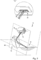
- eine perspektivische Darstellung eines Ausführungsbeispiels eines erfindungsgemäßen Lichtmoduls, das einen an einem zusätzlichen Umlenkspiegel gefalteten Strahlengang aufweist;
- Fig. 7
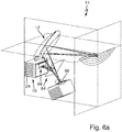
- den Gegenstand der
Fig. 6 mit verschiedenen Ausgestaltungen des Umlenkspiegels, jeweils in einer Seitenansicht; - Fig. 8
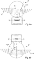
- Vorderansichten von zwei Ausgestaltungen erfindungsgemäßer Lichtmodule mit Anordnungen der Ersatzlichtquelle gemäß den Alternativen der
Fig. 1 und derFig. 2 ; - Fig. 9
- eine von einem Ausführungsbeispiel eines erfindungsgemäßen Lichtmoduls im Vorfeld des Lichtmoduls erzeugte Abblendlichtverteilung und eine schematische Darstellung von Lichtquellenbildern, aus denen sich die Abblendlichtverteilung zusammensetzt.
- Fig. 1
- an embodiment of a light module according to the invention with a replacement light source located below the secondary optics;
- Fig. 2
- an embodiment of a light module according to the invention with a replacement light source located above the secondary optics;
- Fig. 3
- various views of an assembly made up of circuit board, LEDs and primary optics with partial areas of a light module not according to the invention, implemented as reflectors;
- Fig. 4
- different views of an assembly of circuit board, LEDs and primary optics with partial areas implemented as converging lenses;
- Fig. 5
- different views of an assembly of circuit board, LEDs and primary optics with partial areas realized as light guides of a light module not according to the invention;
- Fig. 6
- a perspective view of an embodiment of an inventive Light module which has a beam path folded on an additional deflecting mirror;
- Fig. 7
- the subject of
Fig. 6 with different configurations of the deflection mirror, each in a side view; - Fig. 8
- Front views of two configurations of light modules according to the invention with arrangements of the substitute light source according to the alternatives of FIG
Fig. 1 and theFig. 2 ; - Fig. 9
- a low beam distribution generated by an exemplary embodiment of a light module according to the invention in advance of the light module and a schematic representation of light source images from which the low beam distribution is composed.
Gleiche Bezugszeichen verweisen in den Figuren auf gleiche oder zumindest ihrer Funktion nach vergleichbare Elemente.The same reference symbols in the figures refer to the same or at least comparable elements in terms of their function.
Im Einzelnen zeigt die
Die Lichtquellenbaugruppe 10 und die Sekundäroptik 12 sind dabei so angeordnet, dass sie eine regelkonforme Lichtverteilung 16 auf einem im Vorfeld des Lichtmoduls stehenden Schirm 17 erzeugen. Die Lichtverteilung 16 weist im dargestellten Fall eine abschnittsweise horizontal verlaufende Hell-Dunkel-Grenze 18 auf.The
Bei einer bestimmungsgemäßen Verwendung des Lichtmoduls 14 in einem Kraftfahrzeugscheinwerfer eines Kraftfahrzeugs, das auf einem ebenen Untergrund steht, verläuft der fahrbahnnähere Teil 18.1 der horizontalen Hell-Dunkel-Grenze etwa auf der Höhe des Horizonts vor dem Fahrzeug oder ganz leicht (in der Regel 0,57°) darunter. Der Punkt, in dem die Hell-Dunkel-Grenze nach oben abknickt, liegt etwa in der Verlängerung der Fahrzeuglängsachse. Eine durch diesen Punkt verlaufende Vertikale V schneidet den Horizont H in einem Punkt des Schirms, der auch als HV = (0,0) bezeichnet wird. Für Einzelheiten einer solchen Lichtverteilung wird auf die Erläuterungen zu
Dem optischen System des Lichtmoduls 14 lässt sich eine Sagittalebene 20 und eine Meridionalebene 22 zuordnen. Die Sagittalebene 20 liegt parallel zur Fahrbahn in der Höhe des Horizonts H. Die Meridionalebene 22 wird von der Richtung der Vertikalen V und einer optischen Achse des Lichtmoduls 14 definiert, die durch den HV = (0,0) Punkt geht.A
Die Lichtquellenbaugruppe 10 umfasst einen Kühlkörper 24 und eine Leiterplatte 26 mit darauf angeordneten SMD-LEDs 28 und der zugehörigen Primäroptik. Die SMD-LEDs mit der zugehörigen Primäroptik 30 sind als Detail Z vergrößert dargestellt.The
Die SMD-LEDs 28 sind bauartbedingt so angeordnet, dass ihre Lichtaustrittsflächen nicht abstandslos aneinander angrenzen. Das von diesen SMD-LEDs 28 emittierte Licht wird durch die Primäroptik 30 so gebündelt, dass sich an den nahtlos aneinandergereihten Lichtaustrittsflächen der Primäroptik 30 eine zusammenhängend geschlossene Zwischenlichtverteilung einstellt. Diese als Ersatzlichtquelle dienende Zwischenlichtverteilung wird anschließend von der Sekundäroptik 12 als Abblendlichtverteilung 16 auf einem entfernt vor dem Lichtmodul 14 stehenden Schirm 17 wiedergegeben. Dabei wird die Unterkante 32 der Primäroptik 30 als Hell-Dunkel-Grenze der Abblendlichtverteilung abgebildet.Due to their design, the
Die Reflektorfläche der Sekundäroptik 12 besteht aus mehreren Reflektorfacetten 12.1, 12.2. 12.3, die zum Beispiel zumindest in Bereichen ihrer Reflexionsfläche als Rotationsparaboloide verwirklicht sind. Dabei nehmen diese Bereiche jeweils den größeren Teil der Reflexionsfläche einer Facette ein. Die für verschiedene Facetten verschiedenen Paraboloide weisen unterschiedliche Brennpunkte 34, 36 auf, die alle auf der Unterkante 32 der Lichtaustrittsfläche der Primäroptik 30 liegen. Die Brennpunkte 34, 36 liegen dabei vorzugsweise an den Ecken der Primäroptik 30. Die Meridionalebene 22 teilt den Raum des optischen Systems in zwei Halbräume. Strahlt die Lichtquelle von unten in den Sekundärspiegel, so liegen die Spiegelfacetten und ihre Brennpunkte im gleichen Halbraum. Die Achsen der Rotationsparaboloide, auf denen die Reflektorfacetten basieren, weisen in Richtung der Abblendlicht-Hell-Dunkel-Grenze 18. In diesem Ausführungsbeispiel wird die Lichtquellenkante als Hell-Dunkel-Grenze der regelkonformen Lichtverteilung abgebildet.The reflector surface of the
Als repräsentativer Lichtstrahl des in der
Die Hauptabstrahlrichtungen der einzelnen LEDs sind bevorzugt parallel zueinander und stimmen insofern überein. Der betrachtete Lichtstrahl 38 verläuft in Hauptabstrahlrichtung der Lichtquellen 28 durch die untere Berandung der Lichtaustrittsfläche der Primäroptik 30 und propagiert in Richtung der Reflektorfläche der Sekundäroptik 12. An der Reflektorfläche wird der Hauptstrahl 38 in spitzem Winkel (< 90°) reflektiert und an einen Punkt an der Hell-Dunkel-Grenze 18 der Lichtverteilung 16 im Bereich H = 0° gelenkt, dessen vertikale Komponente üblicherweise bei V = -0,57° liegt.The main emission directions of the individual LEDs are preferably parallel to one another and in this respect match. The
Der Gegenstand der
Die Aufgabe der Primäroptik 30 besteht innerhalb der hier vorgestellten Erfindung insbesondere darin, eine scharf begrenzte, streifenfreie und insofern als Ersatzlichtquelle geeignete Zwischenlichtverteilung in einer Ebene zu erzeugen, die von der Sekundäroptik 12 in der regelkonformen Lichtverteilung 18 scharf abgebildet wird. Dazu muss die Primäroptik 30 insbesondere aus den nicht abstandlos benachbarten Lichtaustrittsflächen der SMD-LEDs 28 eine geschlossen zusammenhängend leuchtende Fläche erzeugen.The task of the
Zu diesem Zweck werden die SMD-LEDs 28 in einer oder mehreren parallelen Reihen angeordnet. Vor das LED-Array wird nun ein Optikarray 30 aus sammelnden Linsen, Reflektoren oder konischen Lichtleitern in den Strahlengang gebracht, so dass die Lichtaustrittsfläche möglichst gleichmäßig und homogen ausgeleuchtet wird und das abgestrahlte Strahlenbündel keine Lücken aufweist.For this purpose, the
Die Reflektor-Teilbereiche haben dabei rechteckige, insbesondere quadratische Querschnitte. Die Lichtaustrittsflächen der einzelnen Reflektoren 40 reihen sich lückenlos und damit abstandslos aneinander an und begrenzen die resultierende leuchtende Fläche mit scharfen, geraden Kanten 44. Jeder SMD-LED 28 ist je ein Reflektor 40 zugeordnet. Die Mittelpunkte der Reflektoren 40 und die Mittelpunkte der Lichtaustrittsflächen der Lichtquellen 28 haben gleiche Abstände. Die Reihenanordnung der Reflektoren 40 besitzt daher die gleiche Teilung wie die Reihenanordnung der LEDs 28.The reflector subareas have rectangular, in particular square cross-sections. The light exit surfaces of the
In einer Ausgestaltung ist zwischen den Reflektor-Teilbereichen und den LED ein Wärmeschutzblech 46 angeordnet, das die Rückseite der Reflektor-Teilbereiche 40 des Optikarrays 30 vor Strahlung schützt. Natürlich ist das Wärmeschutzblech 46 über den Lichtaustrittsflächen der SMD-LEDs 28 unterbrochen, um einen Lichtaustritt zu erlauben.In one embodiment, a
Insbesondere die
Jeder Lichtquelle 28 ist eindeutig ein Sammellinsenteilbereich 50 zugeordnet. Vergleiche
Alternativ kann diese Kante 54 auch durch eine Blende 56 gebildet werden, die unmittelbar vor der Lichtaustrittsfläche des Linsenarrays in den Strahlengang gebracht wird. Dies ist in der
Die Zwischenlichtverteilung liegt bei den Linsenarrays im Bereich der Linsenkörper. Der Fokus der Sekundäroptik liegt in
Die Blende kann auch in Verbindung mit den übrigen Ausgestaltungen von Primäroptiken, die in dieser Anmeldung vorgestellt werden, verwendet werden.The diaphragm can also be used in conjunction with the other configurations of primary optics presented in this application.
Wie in der
Der LED-Chip 28 liegt zwischen dem Sammellinsenteilbereich 50 und dessen objektseitigem Brennpunkt F. Der LED-Chip 28 wird durch den Sammellinsenteilbereich 50 so vergrößert, dass das (aufrechte) virtuelle Bild 28' des Chips (in Lichtaustrittsrichtung vor dem objektseitigen Linsenbrennpunkt F) etwa gleich groß ist wie der Sammellinsenteilbereich 50, d.h. B'LED ≈ T. Für die angegebenen Größen gelten näherungsweise folgende Zusammenhänge: 
- 0,1 mm ≤ S1 ≤ 2 mm
- 1 x BLED ≤ T ≤ 4 x BLED
- 0.1 mm ≤ S 1 ≤ 2 mm
- 1 x B LED ≤ T ≤ 4 x B LED
Die Sammellinsenteilbereiche 50 des Grundkörpers 52 dienen nicht zur Erzeugung reeller Zwischenbilder der Lichtquellen 28, sondern bilden lediglich eine ausgeleuchtete Fläche auf der Lichtaustrittsseite 25 der Sammellinsenteilbereiche 50. Die Lichtquellen 28 sind derart zwischen den Lichteintrittsflächen der Sammellinsenteilbereiche 50 und den objektseitigen Brennpunkten F der Sammellinsenteilbereiche 50 angeordnet, dass die Ränder der Lichtquellen 28 auf geometrischen Verbindungen von den Brennpunkten F zu den Linsenrändern liegen. Die Abstrahlflächen der Lichtquellen 28 sind senkrecht zu den optischen Achsen der Sammellinsenteilbereiche 50 angeordnet. Dadurch ergibt sich eine sehr gleichmäßige Ausleuchtung der Sammellinsenteilbereiche 50, und auf den Lichtaustrittsflächen der Sammellinsenteilbereiche 50 ergibt sich eine besonders homogene Lichtverteilung, die sog. Zwischenlichtverteilung. Diese Zwischenlichtverteilungen werden durch die Sekundäroptik zur Erzeugung der resultierenden Gesamtlichtverteilung des Lichtmoduls auf der Fahrbahn vor dem Fahrzeug abgebildet. Die optischen Achsen der einzelnen Sammellinsenteilbereiche 50 des Grundkörpers 52 verlaufen alle in einer Ebene, bevorzugt sind sie parallel zueinander. Die Achse der Sekundäroptik ist auf der Seite, die dem Grundkörper 52 zugewandt ist, parallel zu der Achse mindestens einer der Sammellinsenteilbereiche 50. Die LEDs sind ist insbesondere zwischen ihrem jeweiligen Sammellinsenteilbereich und dessen paraxialem Brennpunkt so angeordnet, dass eine lückenlose Zwischenlichtverteilung entsteht, die sich aus den virtuellen Bildern der Lichtaustrittsflächen der einzelnen Chips zusammensetzt. Es wird darauf hingewiesen, dass das Licht hier aus der LED zunächst in Luft austritt und erst dann auf den zugehörigen Sammellinsenteilbereich einfällt. Dies ist ein Unterschied zu Stand der Technik, bei dem LEDs mit transparenten Vergussmassen verwendet werden, wobei der Verguß möglicherweise eine Linsenwirkung entfaltet.The collecting
Die Lichteintrittsfläche ist vorzugsweise eben und steht parallel vor dem LED-Chip. Die Lichtleiter 60 werden wie die zugeordneten Lichtquellen in einer oder mehreren Reihen angeordnet, so dass die Lichtaustrittsflächen wiederum durch mindestens eine Gerade 44 begrenzt werden. Die Lichtaustrittsfläche ist vorzugsweise konvex gewölbt. Das Lichtleiterarray wird bevorzugt aus einem der oben genannten Materialien gefertigt. Das Lichtleiterarray wird bevorzugt als einstückiger Grundkörper gefertigt, der die Lichtleiter als Licht leitende Teilbereiche aufweist.The light entry surface is preferably flat and is parallel in front of the LED chip. Like the assigned light sources, the light guides 60 are arranged in one or more rows, so that the light exit surfaces are again delimited by at least one
Für alle drei Ausgestaltungen des Primäroptikarray als Array von Reflektor-Teilbereichen 40, Sammellinsen-Teilbereichen 50 und Lichtleiter-Teilbereichen 60 gilt, dass die Summe der Lichtaustrittsflächen der jeweiligen Teilbereiche die geschlossen zusammenhängende Zwischenlichtverteilung und Ersatzlichtquelle bildet.For all three configurations of the primary optics array as an array of reflector subareas 40, converging
Vernachlässigt man Verluste durch Absorbtion und Fresnel-Reflexion, dann weist die Ersatzlichtquelle ähnliche Leuchtdichten auf wie die Chips der einzelnen LEDs. Damit weist auch eine solche Ersatzlichtquelle über ihre ganze Lichtaustrittsfläche gleichmäßig verteilte Leuchtdichten und ähnliche Abstrahlwinkel wie einzelne LEDs auf. Damit lässt sich die Ersatzlichtquelle im Folgenden wie ein LED-Array behandeln.If losses due to absorption and Fresnel reflection are neglected, the substitute light source will have luminance levels similar to that of the chips in the individual LEDs. Such a substitute light source thus also has luminance levels evenly distributed over its entire light exit area and radiation angles similar to individual LEDs. The replacement light source can thus be treated like an LED array in the following.
Die so gebildete Lichtverteilung dient nun als Ersatzlichtquelle für eine nachgeschaltete Sekundäroptik, die eine Sammellinse oder bevorzugt ein Reflektor mit zumindest bereichsweise parabolischer Reflexionsfläche ist und die mithilfe dieser Ersatzlichtquelle eine Abblendlichtverteilung formt.The light distribution formed in this way now serves as a substitute light source for a downstream secondary optics, which is a converging lens or preferably a reflector with at least partially parabolic reflection surface and which forms a low beam distribution with the aid of this substitute light source.
Die Ersatzlichtquelle sollte möglichst ähnlich orientiert sein wie die Hell-Dunkel Grenze der Abblendlichtverteilung (nämlich zumindest abschnittsweise horizontal), um eine gute Schärfe der Hell-Dunkel-Grenze zu erzielen (hoher Beleuchtungsstärkegradient). Aus diesem Grund werden auch alle Reflektoren im Strahlengang so angeordnet, dass der Strahlengang an den jeweiligen Reflektoren immer in möglichst spitzem Winkel (<90°) gefaltet wird und die Orientierung der Bilder der Ersatzlichtquelle parallel zur Hell-Dunkel-Grenze weitgehend erhalten bleibt.The alternative light source should be oriented as similarly as possible to the light-dark boundary of the low beam distribution (namely at least in sections horizontally) in order to achieve a good sharpness of the light-dark boundary (high illuminance gradient). For this reason, all reflectors in the beam path are arranged in such a way that the beam path at the respective reflectors is always in is folded as acute as possible (<90 °) and the orientation of the images of the substitute light source parallel to the cut-off line is largely retained.
Vorzugsweise ist die Sekundäroptik ein facettierter Parabolreflektor. Der Reflektor ist so im Strahlengang angeordnet, dass die Ersatzlichtquelle von vorne in den Reflektor hineinstrahlt, so dass der Strahlengang in spitzem Winkel umgelenkt wird. Der mindestens eine Brennpunkt des Reflektors liegt dabei auf dem Rand der Ersatzlichtquelle. Zur Erzeugung einer Abblendlichtverteilung ist dies der untere Rand der Ersatzlichtquelle. Wie beschrieben, kann dieser Rand zusätzlich durch eine Blende abgeschattet werden, um zu verhindern, dass Streulicht ins Dunkelfeld der Lichtverteilung gelangt.The secondary optics are preferably a faceted parabolic reflector. The reflector is arranged in the beam path in such a way that the substitute light source shines into the reflector from the front, so that the beam path is deflected at an acute angle. The at least one focal point of the reflector lies on the edge of the substitute light source. To generate a low beam distribution, this is the lower edge of the substitute light source. As described, this edge can also be shaded by a screen to prevent stray light from entering the dark field of the light distribution.
Besitzt die Sekundäroptik mehrere Reflektorfacetten, so liegen deren Brennpunkte wiederum auf der Kante der Ersatzlichtquelle, werden aber je nach Lage der Facette vorzugsweise an verschiedenen Enden der Lichtquellenkante positioniert:
Strahlt die Lichtquelle von unten in den Reflektor, so haben die jeweiligen Parabelfacetten ihren Brennpunkt immer im selben von der Meridionalebene begrenzten Halbraum. Strahlt die Lichtquelle von oben in den Reflektor, liegen die Brennpunkte der Parabelfacetten immer auf der anderen Seite der Meridionalebene wie die Reflektorfacette selbst.If the secondary optics has several reflector facets, their focal points are again on the edge of the substitute light source, but are preferably positioned at different ends of the light source edge depending on the position of the facet:
If the light source shines into the reflector from below, the respective parabolic facets always have their focal point in the same half-space delimited by the meridional plane. If the light source shines into the reflector from above, the focal points of the parabolic facets are always on the other side of the meridional plane like the reflector facet itself.
Dadurch wird gewährleistet, dass die Bilder der Ersatzlichtquelle immer mit der am nächsten liegenden Ecke an die Abblendlicht-Hell-Dunkel-Grenze anschließen und kein Teil der Lichtquellenbilder in das Dunkelfeld der Lichtverteilung hineinragt.This ensures that the images of the substitute light source always connect with the corner closest to the low-beam light-dark border and that no part of the light source images goes into the dark field of the Light distribution protrudes.
Die Sekundäroptik fokussiert nicht auf die Chipebene der LEDs sondern auf die Unterkante der Lichtaustrittsfläche der Primäroptik. Die Lichtaustrittsfläche kann besonders scharf begrenzt werden, wenn entlang des Randes der Lichtaustrittsfläche, eine Blende angeordnet wird, die alles Licht abschattet, das an der Lichtaustrittsfläche vorbeigestreut wird.The secondary optics do not focus on the chip level of the LEDs but on the lower edge of the light exit surface of the primary optics. The light exit surface can be delimited particularly sharply if a screen is arranged along the edge of the light exit surface which shades all light that is scattered past the light exit surface.
Die Sekundäroptik fokussiert in diesem Fall möglichst direkt auf die Blendenkante. Soll eine Abblendlichtverteilung mit zumindest abschnittsweise horizontal verlaufender Hell-Dunkel-Grenze erzeugt werden, so verläuft die Blendenkante entlang des unteren Randes der Lichtaustrittsfläche der Primäroptik, mit deren Hilfe dann durch die Sekundäroptik der Hell-Dunkel-Übergang der Lichtverteilung gebildet wird.In this case, the secondary optics focus as directly as possible on the diaphragm edge. If a low-beam light distribution with at least partially horizontal light-dark border is to be generated, the diaphragm edge runs along the lower edge of the light exit surface of the primary optics, with the help of which the light-dark transition of the light distribution is then formed by the secondary optics.
Die Reflektorfläche der Sekundäroptik besteht bevorzugt aus mehreren Reflektorfacetten, die jeweils als Rotationsparaboloide verwirklichte Flächen aufweisen. Die verschiedenen Paraboloide weisen unterschiedliche Brennpunkte auf, die alle auf der Unterkante der Lichtaustrittsfläche der Primäroptik liegen und zwar vorzugsweise an deren Rändern (Ecken), wobei die Brennpunkte in der gleichen Hemisphäre liegen wie die dazugehörenden Facettenflächen.The reflector surface of the secondary optics preferably consists of several reflector facets, each of which has surfaces implemented as paraboloids of revolution. The different paraboloids have different focal points, all of which are located on the lower edge of the light exit surface of the primary optics, preferably at its edges (corners), the focal points being in the same hemisphere as the associated facet surfaces.
Die Achsen der Rotationsparaboloide, auf denen die Reflektorfacetten basieren, weisen in Richtung der Abblendlicht-Hell-Dunkel-Grenze. Damit wird die Lichtquellenkante als Hell-Dunkel-Grenze der Lichtverteilung abgebildet.The axes of the paraboloids of revolution, on which the reflector facets are based, point in the direction of the low-beam light-dark boundary. In this way, the edge of the light source is mapped as a cut-off line for the light distribution.
In einer Ausgestaltung werden die Reflektorfacetten statt als Rotationsparaboloide als torische Flächen ausgeführt: Hierzu wird die Krümmung des Rotationsparaboloids in Schnitten parallel zur Hell-Dunkel-Grenze (bzw. zu Abschnitten der Hell-Dunkel-Grenze) durch den Brennpunkt des Paraboloids so erhöht oder verringert, dass sich anstelle des Brennpunktes eine Brennlinie ergibt, die parallel zur Abblendlicht-Hell-Dunkel-Grenze bzw. zu Abschnitten der Abblendlicht-Hell-Dunkel-Grenze verläuft. Die Streuung kann auch durch streuende Zylinderoptiken erreicht werden, die auf die Facettenflächen aufgebracht werden und deren Zylinderachse senkrecht auf Hauptstrahl und Abblendlicht-Hell-Dunkel-Grenze stehen.In one embodiment, the reflector facets are designed as toric surfaces instead of paraboloids of revolution: For this purpose, the curvature of the paraboloid of revolution is increased or decreased in sections parallel to the light-dark boundary (or to sections of the light-dark boundary) through the focal point of the paraboloid that instead of the focal point there is a focal line which runs parallel to the low beam / light / dark border or to sections of the low beam / light / dark border. The scattering can also be achieved by scattering cylinder optics, which are applied to the facet surfaces and whose cylinder axis is perpendicular to the main ray and the low-beam light-dark boundary.
Soll eine asymmetrische Abblendlicht-Hell-Dunkel-Grenze mit Anstieg erzeugt werden, so wird dieser Anstieg über eine Reflektorfacette erzeugt, die möglichst nahe am Rand der Reflektorfläche liegt. Einzelheiten dazu werden weiter unten unter Bezug auf die
So bietet es konstruktive Vorteile, wenn die Lichtquelle 10 in Fahrtrichtung (Lichtabstrahlrichtung) nach vorne abstrahlt und die Entwärmung der Lichtquelle über einen Kühlkörper 24 nach hinten erfolgt: Eine derartige Lichtquelle kann auf einfache Weise von der Rückseite des Scheinwerfers gewechselt werden. Auch lässt sich der Kühlkörper auf der Rückseite des Lichtmoduls leichter belüften, was die Kühlleistung verbessert. Darüber erhält man ein kompaktes Lichtmodul, dessen Schwerpunkt in der Nähe der Lichtaustrittsfläche liegt, was das mechanische Schwenken des Lichtmoduls 14 erleichtert.It offers structural advantages if the
Das Falten des Strahlenganges ist auch deshalb günstig, weil sich die Brechkraft bei dem vorgeschlagenen optischen System auf Primär- und Sekundäroptik aufteilt, so dass man Sekundäroptiken mit geringer Brechkraft, d.h. mit langer Brennweite erhält (die Brennweiten sind 2-3 mal größer als bei einstufigen Systemen).The folding of the beam path is also favorable because the refractive power in the proposed optical system is divided into primary and secondary optics, so that secondary optics with low refractive power, i.e. with a long focal length (the focal lengths are 2-3 times larger than with single-stage systems).
Der Umlenkspiegel 64 wird als Hyperboloid ausgeführt, wobei das Hyperboloid ausdrücklich auch den Spezial-Fall des ebenen Spiegels beinhalten soll. Die beschriebenen Eigenschaften der Sekundäroptik 12 beziehen sich in diesem Fall auf das optische System 64, 12 aus Umlenkspiegel 64 und Sekundäroptik 12, das nun mit einem oder mehreren Brennpunkten auf die untere Kante der Ersatzlichtquelle fokussiert. Der Umlenkspiegel 64 erzeugt dabei mindestens ein virtuelles Zwischenbild 66 der Ersatzlichtquelle 68.The
Die Ersatzlichtquelle 68 liegt dabei in der objektseitigen Petzvalfläche des hyperbolischen Umlenkspiegels, während der oder die Brennpunkte der Sekundäroptik 12 in der bildseitigen Petzvalfläche des Hyperboloids liegen, d.h. die Sekundäroptik 12 fokussiert statt auf die reelle Ersatzlichtquelle 68 auf deren virtuelles Bild 66.The substitute
Das optische System aus Umlenkoptik 64 und Sekundäroptik 12 ist bevorzugt so ausgestaltet, dass die Bedingung![]()
![]()
Ein optisches System aus Umlenkoptik 64 und Sekundäroptik 12, das die Bedingung ![]()
![]()
In Bezug auf den Umlenkspiegel 64 werden fünf Ausgestaltungen unterschieden. In einer ersten Ausgestaltung ist der Umlenkspiegel 64 ein ebener Spiegel. Dies ist in der
Die
In einer nicht dargestellten vierten Ausgestaltung besitzt das Lichtmodul mehrere ebene Umlenkspiegelfacetten und eine Sekundäroptik mit einem einzelnen objektseitigen Brennpunkt. Der facettierte Umlenkspiegel teilt den Strahlengang der Sekundäroptik auf und erzeugt so ein optisches System mit mehreren Brennpunkten, ähnlich wie es bei einem facettierten Parabelreflektor der Fall ist. Der facettierte Umlenkspiegel erzeugt mehrere gegeneinander verschobene virtuelle Bilder der Ersatzlichtquelle. Die Brennpunkte der zweiteiligen Sekundäroptik fokussieren wie oben beschrieben auf den Rand der Ersatzlichtquelle.In a fourth embodiment, not shown, the light module has a plurality of flat deflecting mirror facets and secondary optics with a single focal point on the object side. The faceted deflecting mirror divides the beam path of the secondary optics and thus creates an optical system with several focal points, similar to a faceted parabolic reflector. The faceted deflecting mirror generates several virtual images of the substitute light source that are shifted relative to one another. The focal points of the two-part secondary optics focus on the edge of the substitute light source as described above.
In einer ebenfalls nicht dargestellten fünften Ausgestaltung weist das Lichtmodul als Umlenkspiegel ein facettiertes Hyperboloid mit einem objektseitigen und mehreren bildseitigen Brennpunkten auf. Die Sekundäroptik soll in diesem Fall einen objektseitigen und einen bildseitigen Brennpunkt (letzteren im Unendlichen) aufweisen. Das facettierte Hyperboloid erzeugt gegeneinander verschobene, vergrößerte (konkaver Hyperbolspiegel) oder verkleinerte (konvexer Hyperbolspiegel) virtuelle Bilder der Lichtquelle, je nachdem, ob der Hyperbolspiegel konkav (und damit vergrößernd) oder konvex (und damit verkleinernd) geformt ist.In a fifth embodiment, likewise not shown, the light module has a faceted hyperboloid as a deflecting mirror with one object-side and several image-side focal points. In this case, the secondary optics should have an object-side and an image-side focus (the latter at infinity). The faceted hyperboloid generates virtual images of the light source that are shifted, enlarged (concave hyperbolic mirror) or reduced (convex hyperbolic mirror), depending on whether the hyperbolic mirror is concave (and thus enlarging) or convex (and thus reducing).
Die Primäroptik vergrößert die Lichtaustrittsfläche um einen Faktor, der etwa dem Quotienten aus der Teilung des Optikarrays und der Seitenlänge eines einzelnen Chips entspricht. Das folgt aus der gleichmäßig hellen Ersatzlichtquelle. Die Brennweite der Sekundäroptik entspricht bevorzugt dem 50 - fachen bis 200 - fachen der Seitenlänge eines einzelnen Chips, insbesondere dem 80 - fachen bis 100- fachen der genannten Seitenlänge.The primary optics enlarge the light exit surface by a factor that corresponds roughly to the quotient of the division of the optics array and the side length of an individual chip. This follows from the equally bright substitute light source. The focal length of the secondary optics preferably corresponds to 50 times to 200 times the side length of an individual chip, in particular 80 times to 100 times the stated side length.
Claims (13)
- Light module (14) of a motor vehicle headlamp, comprising a plurality of light-emitting diodes as light sources (28), a primary optic (30) and a secondary optic (12), the primary optic being designed to collect light emanating from the light sources and to convert it into an intermediate light distribution (68) having the form of a closed luminous surface, and wherein the secondary optic has a focal length on the object side, the primary optic and the secondary optic being arranged in such a way that the intermediate light distribution lies in the light path at the distance of this focal length in front of the secondary optic, the light module being designed to generate a low beam light distribution with a light/dark boundary, characterized in that the primary optics is a one-piece base body constructed from collecting lens sub-regions (50), and in that the chip of a light-emitting diode is located between a collecting lens sub-region (50) collecting light from this light-emitting diode and its object-side focal point (F), wherein light exit surfaces of the light sources (28) are separated from each other by distances between them and that the primary optics is arranged to distribute light emanating from the light sources in such a way that the distances in the intermediate light distribution (68) are not visible, so that a closed luminous surface is created in the intermediate light distribution (68).
- Light module (14) according to claim 1, characterised in that the primary optics (30) has a separate optically effective partial region for each light source, each of which has a light emission surface, and wherein these light emission surfaces adjoin one another without spacing, and wherein at least two adjacent light emission surfaces thus adjoin one another, in that at least one side edge of a first of two adjacent light emission surfaces lies in line with a side edge of the second of the two adjacent light emission surfaces, so that the two aligned edges form a common straight edge (44).
- Light module (14) according to claim 2, characterised in that each partial area is a collecting lens (50).
- Light module (14) according to one of the preceding claims, characterised in that the light module has a diaphragm (56) which is arranged in the beam path of the light immediately behind the light exit surface in such a way that it shades part of the intermediate light distribution.
- Light module (14) according to one of the preceding claims, characterised in that the secondary optics comprises at least one concave mirror reflector (12).
- Light module (14) according to claim 5, characterised in that an optical surface of the secondary optics is divided into a larger partial area and a smaller partial area, the larger partial area being defined in that it has a first focal point on the object side and that the two partial areas have a common focal point at infinity on the image side.
- Light module (14) according to claim 5, characterised in that the concave mirror reflector has a reflecting surface, the larger part of which has a parabolic shape, wherein an object-side focal point of the parabolic shape lies on the light exit surface of the primary optics.
- Light module (14) according to claim 5, characterized in that the secondary optics consists of two mirrors which are arranged one behind the other in the beam path in such a way that they fold the beam path of the secondary optics twice at an acute angle and that the secondary optics has an object-side focal point which lies on the light exit surface of the primary optics and whose image point lies at infinity.
- Light module (14) according to claim 8, characterized in that the first mirror (64) in the beam path in the direction of propagation of the light is a hyperboloid and the second mirror is a paraboloid (12), the object-side focus of the hyperboloid forming the object-side focus of the secondary optics and the image-side focus of the hyperboloid coinciding with the focus of the paraboloid and marking the position of a virtual intermediate image of the intermediate light distribution.
- Light module (14) according to one of the preceding claims, characterized in that the secondary optics has several object side focal points and one or more common image side focal points or focal lines at infinity.
- Light module (14) according to claim 8 or 9, characterized in that the first mirror (64) of the two-stage secondary optics is a hyperboloid or a plane mirror as a special case of the hyperboloid, and that the second mirror (12) is a faceted paraboloid, wherein the object-side focal point of the hyperboloid forms the object-side focal point of the secondary optics and wherein the image-side focal point of the hyperboloid marks the position of a virtual intermediate image of the intermediate light distribution and wherein the downstream parabolic facets are arranged to focus on the edge of the virtual image of the intermediate light distribution.
- Light module (14) according to claim 8 or 9, characterized in that the first mirror (64) of the two-stage secondary optics is a faceted hyperboloid or as its special case a faceted plane mirror and that the second mirror (12) is a paraboloid, wherein the object-side focal point of the hyperboloid forms the object-side focal point of the secondary optics and wherein the image-side focal point of the hyperboloid marks the position of a virtual intermediate image of the intermediate light distribution and wherein the parabolic facets arranged downstream in the beam path focus on the edge of the virtual image of the intermediate light distribution.
- Light module (14) according to claim 8 or 9, characterised in that the two mirrors (64, 12) have several focal points on the object side which lie on the edge of the intermediate light distribution and whose image point or image lines lie on the light-dark boundary of the light distribution at infinity, wherein the two mirror surfaces are shaped in such a way that all optical paths between the focal point on the object side and its respective image points or image lines are of equal length.
Applications Claiming Priority (1)
| Application Number | Priority Date | Filing Date | Title |
|---|---|---|---|
| DE102013207845.5A DE102013207845A1 (en) | 2013-04-29 | 2013-04-29 | Light module for a motor vehicle headlight |
Publications (3)
| Publication Number | Publication Date |
|---|---|
| EP2799762A2 EP2799762A2 (en) | 2014-11-05 |
| EP2799762A3 EP2799762A3 (en) | 2016-09-14 |
| EP2799762B1 true EP2799762B1 (en) | 2020-12-02 |
Family
ID=50513056
Family Applications (1)
| Application Number | Title | Priority Date | Filing Date |
|---|---|---|---|
| EP14164995.4A Active EP2799762B1 (en) | 2013-04-29 | 2014-04-16 | Light module for a motor vehicle headlamp |
Country Status (4)
| Country | Link |
|---|---|
| US (1) | US9546766B2 (en) |
| EP (1) | EP2799762B1 (en) |
| CN (1) | CN104121533A (en) |
| DE (1) | DE102013207845A1 (en) |
Families Citing this family (17)
| Publication number | Priority date | Publication date | Assignee | Title |
|---|---|---|---|---|
| KR101529166B1 (en) * | 2013-08-06 | 2015-06-16 | 현대모비스 주식회사 | Lamp for vehicle |
| DE102014225075A1 (en) | 2014-12-05 | 2016-06-09 | Osram Gmbh | lighting device |
| DE102014226646A1 (en) | 2014-12-19 | 2016-06-23 | Osram Gmbh | lighting device |
| KR101795229B1 (en) * | 2016-03-31 | 2017-11-08 | 현대자동차주식회사 | Lamp apparatus for a vehicle |
| CN106197657B (en) * | 2016-06-29 | 2017-12-12 | 北京经纬恒润科技有限公司 | The detection method of vehicle environment illuminance, device and system |
| AT518905B1 (en) * | 2016-07-29 | 2018-04-15 | Zkw Group Gmbh | Projection device for a motor vehicle headlight and method for its production |
| TWI642568B (en) * | 2016-09-07 | 2018-12-01 | 世正光電股份有限公司 | Illumination structure and light distribution method thereof |
| FR3056691B1 (en) * | 2016-09-29 | 2019-06-28 | Valeo Vision | OPTICAL MODULE FOR A MOTOR VEHICLE PROJECTOR WITH ADAPTIVE LIGHTING FUNCTION, COMPRISING AN OPTICAL LIGHT BEAM REFLECTING SYSTEM |
| DE102016125676A1 (en) * | 2016-12-23 | 2018-06-28 | Automotive Lighting Reutlingen Gmbh | LED module and lighting device for a motor vehicle with a plurality of such LED modules |
| US10240737B2 (en) * | 2017-03-06 | 2019-03-26 | Ford Global Technologies, Llc | Vehicle light assembly |
| DE102017117560A1 (en) * | 2017-08-02 | 2019-02-07 | Automotive Lighting Reutlingen Gmbh | Light module and method for operating the light module |
| DE102018102156A1 (en) | 2018-01-31 | 2019-08-01 | Automotive Lighting Reutlingen Gmbh | Light generation arrangement and motor vehicle light |
| ES2965827T3 (en) * | 2018-03-14 | 2024-04-17 | Tyc Brother Ind Co Ltd | Vehicle Headlight Assembly |
| JP7127492B2 (en) * | 2018-11-05 | 2022-08-30 | トヨタ自動車株式会社 | Vehicle headlight device |
| CN111322587B (en) * | 2018-12-13 | 2022-09-02 | 深圳市中光工业技术研究院 | Light source device |
| FR3093788B1 (en) * | 2019-03-14 | 2022-05-27 | Valeo Vision | LIGHT DEVICE IMAGES A VIRTUAL ILLUMINATED SURFACE OF A COLLECTOR |
| EP3757451B1 (en) * | 2019-06-24 | 2023-08-09 | ZKW Group GmbH | Lighting device for a motor vehicle |
Family Cites Families (16)
| Publication number | Priority date | Publication date | Assignee | Title |
|---|---|---|---|---|
| US20050030759A1 (en) * | 2003-08-04 | 2005-02-10 | Guide Corporation | Bifocal hyperbolic catadioptric collection system for an automotive lamp |
| EP1920187B2 (en) * | 2005-08-31 | 2018-09-12 | Osram Sylvania, Inc. | Led headlamp system |
| AT504668B1 (en) * | 2007-01-11 | 2008-07-15 | Zizala Lichtsysteme Gmbh | TOTAL REFLECTION SYSTEM FOR A HEADLIGHT OR A LIGHT UNIT OF A MOTOR VEHICLE |
| DE102008013603B4 (en) * | 2008-03-11 | 2017-06-22 | Automotive Lighting Reutlingen Gmbh | Light module for a lighting device |
| JP4582190B2 (en) * | 2008-05-14 | 2010-11-17 | 市光工業株式会社 | Vehicle lighting |
| FR2932245B1 (en) * | 2008-06-06 | 2010-09-10 | Valeo Vision Sas | LIGHTING MODULE FOR MOTOR VEHICLE PROJECTOR |
| DE102009035544B4 (en) * | 2009-07-31 | 2019-10-24 | Volkswagen Ag | Headlamp in a motor vehicle with multiple semiconductor light sources |
| DE102009053581B3 (en) * | 2009-10-05 | 2011-03-03 | Automotive Lighting Reutlingen Gmbh | Light module for a lighting device of a motor vehicle |
| EP2553319B1 (en) * | 2010-03-31 | 2017-03-01 | Koninklijke Philips N.V. | Lighting system and light source unit for such a system |
| JP5666882B2 (en) * | 2010-11-18 | 2015-02-12 | 株式会社小糸製作所 | High beam lamp unit |
| EP2500628B1 (en) * | 2011-03-14 | 2020-05-06 | Stanley Electric Co., Ltd. | Vehicle headlamp |
| CN202274394U (en) * | 2011-05-11 | 2012-06-13 | 鹤壁市恒通电气有限公司 | Direct-lighting type lens front fog lamp |
| CN105351839B (en) | 2011-09-01 | 2018-02-27 | 株式会社小糸制作所 | Vehicle headlamp apparatus |
| DE102011054229B4 (en) * | 2011-10-06 | 2022-07-28 | HELLA GmbH & Co. KGaA | Lighting device for vehicles |
| CN202660430U (en) * | 2012-04-12 | 2013-01-09 | 安徽华东光电技术研究所 | Novel xenon electric discharge lamp for planes |
| DE102013206488A1 (en) * | 2013-04-11 | 2014-10-30 | Automotive Lighting Reutlingen Gmbh | Light module for a motor vehicle lighting device |
-
2013
- 2013-04-29 DE DE102013207845.5A patent/DE102013207845A1/en not_active Ceased
-
2014
- 2014-04-16 EP EP14164995.4A patent/EP2799762B1/en active Active
- 2014-04-28 CN CN201410175762.5A patent/CN104121533A/en active Pending
- 2014-04-29 US US14/264,761 patent/US9546766B2/en active Active
Non-Patent Citations (1)
| Title |
|---|
| None * |
Also Published As
| Publication number | Publication date |
|---|---|
| US20140321140A1 (en) | 2014-10-30 |
| US9546766B2 (en) | 2017-01-17 |
| EP2799762A3 (en) | 2016-09-14 |
| EP2799762A2 (en) | 2014-11-05 |
| CN104121533A (en) | 2014-10-29 |
| DE102013207845A1 (en) | 2014-10-30 |
Similar Documents
| Publication | Publication Date | Title |
|---|---|---|
| EP2799762B1 (en) | Light module for a motor vehicle headlamp | |
| EP2910847B1 (en) | Light module of a motor vehicle headlight and headlight with such a light module | |
| EP2587125B1 (en) | Headlamp projection module for a motor vehicle | |
| EP2799761B1 (en) | Light module for a motor vehicle headlamp | |
| EP2789900B1 (en) | Light module for a motor vehicle lighting device | |
| EP2616738B1 (en) | Motor vehicle headlight comprising a multifunctional projection module | |
| DE102012202290B4 (en) | Light module for a glare-free motor vehicle high beam | |
| EP2505910B1 (en) | Motor vehicle headlamp with a semiconductor light source | |
| DE102014200368B4 (en) | Partial remote light projection light module for a motor vehicle headlight | |
| EP2789901B1 (en) | Light module of a motor vehicle lighting device | |
| EP1818600B1 (en) | Dipped headlight with hot spot generation | |
| DE102011013211A1 (en) | Motor vehicle headlight with a multi-function projection module | |
| EP1818599A2 (en) | Dipped headlight which creates a strongly contrasted cut-off | |
| EP3301350B1 (en) | Light module for a motor vehicle headlamp | |
| EP2730836B1 (en) | Light module for a headlight of a motor vehicle | |
| DE102012202508A1 (en) | Single-piece light conductor device for headlight, of motor car, has light guidance fingers whose boundary surfaces fulfill conditions mentioned in preamble, so that straight line of fingers is extended in sagittal surface of device | |
| EP3524873B1 (en) | Efficient projection light module comprising microprojectors for a motor vehicle headlamp | |
| EP3765781B1 (en) | Light module for motor vehicle headlight | |
| DE102013215359B3 (en) | Mechanically-free bend lighting module | |
| DE102021107851B4 (en) | VEHICLE LAMP AND VEHICLE | |
| DE102020117785A1 (en) | Motor vehicle headlights with a light source with a square light-emitting surface | |
| DE102016208138A1 (en) | Illuminating device for emitting illumination light |
Legal Events
| Date | Code | Title | Description |
|---|---|---|---|
| PUAI | Public reference made under article 153(3) epc to a published international application that has entered the european phase |
Free format text: ORIGINAL CODE: 0009012 |
|
| 17P | Request for examination filed |
Effective date: 20140416 |
|
| AK | Designated contracting states |
Kind code of ref document: A2 Designated state(s): AL AT BE BG CH CY CZ DE DK EE ES FI FR GB GR HR HU IE IS IT LI LT LU LV MC MK MT NL NO PL PT RO RS SE SI SK SM TR |
|
| AX | Request for extension of the european patent |
Extension state: BA ME |
|
| PUAL | Search report despatched |
Free format text: ORIGINAL CODE: 0009013 |
|
| AK | Designated contracting states |
Kind code of ref document: A3 Designated state(s): AL AT BE BG CH CY CZ DE DK EE ES FI FR GB GR HR HU IE IS IT LI LT LU LV MC MK MT NL NO PL PT RO RS SE SI SK SM TR |
|
| AX | Request for extension of the european patent |
Extension state: BA ME |
|
| RIC1 | Information provided on ipc code assigned before grant |
Ipc: F21S 8/10 20060101AFI20160808BHEP |
|
| STAA | Information on the status of an ep patent application or granted ep patent |
Free format text: STATUS: REQUEST FOR EXAMINATION WAS MADE |
|
| R17P | Request for examination filed (corrected) |
Effective date: 20170314 |
|
| RBV | Designated contracting states (corrected) |
Designated state(s): AL AT BE BG CH CY CZ DE DK EE ES FI FR GB GR HR HU IE IS IT LI LT LU LV MC MK MT NL NO PL PT RO RS SE SI SK SM TR |
|
| REG | Reference to a national code |
Ref country code: DE Ref legal event code: R079 Ref document number: 502014015059 Country of ref document: DE Free format text: PREVIOUS MAIN CLASS: F21S0008100000 Ipc: F21S0041147000 |
|
| RIC1 | Information provided on ipc code assigned before grant |
Ipc: F21S 41/36 20180101ALI20191129BHEP Ipc: F21S 41/33 20180101ALI20191129BHEP Ipc: F21S 41/32 20180101ALI20191129BHEP Ipc: F21S 41/147 20180101AFI20191129BHEP Ipc: F21S 41/24 20180101ALI20191129BHEP Ipc: F21S 41/155 20180101ALI20191129BHEP Ipc: F21S 41/20 20180101ALI20191129BHEP |
|
| GRAP | Despatch of communication of intention to grant a patent |
Free format text: ORIGINAL CODE: EPIDOSNIGR1 |
|
| STAA | Information on the status of an ep patent application or granted ep patent |
Free format text: STATUS: GRANT OF PATENT IS INTENDED |
|
| INTG | Intention to grant announced |
Effective date: 20200121 |
|
| GRAJ | Information related to disapproval of communication of intention to grant by the applicant or resumption of examination proceedings by the epo deleted |
Free format text: ORIGINAL CODE: EPIDOSDIGR1 |
|
| STAA | Information on the status of an ep patent application or granted ep patent |
Free format text: STATUS: REQUEST FOR EXAMINATION WAS MADE |
|
| INTC | Intention to grant announced (deleted) | ||
| GRAP | Despatch of communication of intention to grant a patent |
Free format text: ORIGINAL CODE: EPIDOSNIGR1 |
|
| STAA | Information on the status of an ep patent application or granted ep patent |
Free format text: STATUS: GRANT OF PATENT IS INTENDED |
|
| INTG | Intention to grant announced |
Effective date: 20200626 |
|
| GRAS | Grant fee paid |
Free format text: ORIGINAL CODE: EPIDOSNIGR3 |
|
| GRAA | (expected) grant |
Free format text: ORIGINAL CODE: 0009210 |
|
| STAA | Information on the status of an ep patent application or granted ep patent |
Free format text: STATUS: THE PATENT HAS BEEN GRANTED |
|
| AK | Designated contracting states |
Kind code of ref document: B1 Designated state(s): AL AT BE BG CH CY CZ DE DK EE ES FI FR GB GR HR HU IE IS IT LI LT LU LV MC MK MT NL NO PL PT RO RS SE SI SK SM TR |
|
| REG | Reference to a national code |
Ref country code: GB Ref legal event code: FG4D Free format text: NOT ENGLISH |
|
| REG | Reference to a national code |
Ref country code: AT Ref legal event code: REF Ref document number: 1341320 Country of ref document: AT Kind code of ref document: T Effective date: 20201215 Ref country code: CH Ref legal event code: EP |
|
| REG | Reference to a national code |
Ref country code: DE Ref legal event code: R096 Ref document number: 502014015059 Country of ref document: DE |
|
| REG | Reference to a national code |
Ref country code: IE Ref legal event code: FG4D Free format text: LANGUAGE OF EP DOCUMENT: GERMAN |
|
| PG25 | Lapsed in a contracting state [announced via postgrant information from national office to epo] |
Ref country code: NO Free format text: LAPSE BECAUSE OF FAILURE TO SUBMIT A TRANSLATION OF THE DESCRIPTION OR TO PAY THE FEE WITHIN THE PRESCRIBED TIME-LIMIT Effective date: 20210302 Ref country code: FI Free format text: LAPSE BECAUSE OF FAILURE TO SUBMIT A TRANSLATION OF THE DESCRIPTION OR TO PAY THE FEE WITHIN THE PRESCRIBED TIME-LIMIT Effective date: 20201202 Ref country code: RS Free format text: LAPSE BECAUSE OF FAILURE TO SUBMIT A TRANSLATION OF THE DESCRIPTION OR TO PAY THE FEE WITHIN THE PRESCRIBED TIME-LIMIT Effective date: 20201202 Ref country code: GR Free format text: LAPSE BECAUSE OF FAILURE TO SUBMIT A TRANSLATION OF THE DESCRIPTION OR TO PAY THE FEE WITHIN THE PRESCRIBED TIME-LIMIT Effective date: 20210303 |
|
| REG | Reference to a national code |
Ref country code: NL Ref legal event code: MP Effective date: 20201202 |
|
| PG25 | Lapsed in a contracting state [announced via postgrant information from national office to epo] |
Ref country code: SE Free format text: LAPSE BECAUSE OF FAILURE TO SUBMIT A TRANSLATION OF THE DESCRIPTION OR TO PAY THE FEE WITHIN THE PRESCRIBED TIME-LIMIT Effective date: 20201202 Ref country code: PL Free format text: LAPSE BECAUSE OF FAILURE TO SUBMIT A TRANSLATION OF THE DESCRIPTION OR TO PAY THE FEE WITHIN THE PRESCRIBED TIME-LIMIT Effective date: 20201202 Ref country code: LV Free format text: LAPSE BECAUSE OF FAILURE TO SUBMIT A TRANSLATION OF THE DESCRIPTION OR TO PAY THE FEE WITHIN THE PRESCRIBED TIME-LIMIT Effective date: 20201202 Ref country code: BG Free format text: LAPSE BECAUSE OF FAILURE TO SUBMIT A TRANSLATION OF THE DESCRIPTION OR TO PAY THE FEE WITHIN THE PRESCRIBED TIME-LIMIT Effective date: 20210302 |
|
| PG25 | Lapsed in a contracting state [announced via postgrant information from national office to epo] |
Ref country code: HR Free format text: LAPSE BECAUSE OF FAILURE TO SUBMIT A TRANSLATION OF THE DESCRIPTION OR TO PAY THE FEE WITHIN THE PRESCRIBED TIME-LIMIT Effective date: 20201202 Ref country code: NL Free format text: LAPSE BECAUSE OF FAILURE TO SUBMIT A TRANSLATION OF THE DESCRIPTION OR TO PAY THE FEE WITHIN THE PRESCRIBED TIME-LIMIT Effective date: 20201202 |
|
| REG | Reference to a national code |
Ref country code: LT Ref legal event code: MG9D |
|
| PG25 | Lapsed in a contracting state [announced via postgrant information from national office to epo] |
Ref country code: LT Free format text: LAPSE BECAUSE OF FAILURE TO SUBMIT A TRANSLATION OF THE DESCRIPTION OR TO PAY THE FEE WITHIN THE PRESCRIBED TIME-LIMIT Effective date: 20201202 Ref country code: RO Free format text: LAPSE BECAUSE OF FAILURE TO SUBMIT A TRANSLATION OF THE DESCRIPTION OR TO PAY THE FEE WITHIN THE PRESCRIBED TIME-LIMIT Effective date: 20201202 Ref country code: PT Free format text: LAPSE BECAUSE OF FAILURE TO SUBMIT A TRANSLATION OF THE DESCRIPTION OR TO PAY THE FEE WITHIN THE PRESCRIBED TIME-LIMIT Effective date: 20210405 Ref country code: SK Free format text: LAPSE BECAUSE OF FAILURE TO SUBMIT A TRANSLATION OF THE DESCRIPTION OR TO PAY THE FEE WITHIN THE PRESCRIBED TIME-LIMIT Effective date: 20201202 Ref country code: CZ Free format text: LAPSE BECAUSE OF FAILURE TO SUBMIT A TRANSLATION OF THE DESCRIPTION OR TO PAY THE FEE WITHIN THE PRESCRIBED TIME-LIMIT Effective date: 20201202 Ref country code: EE Free format text: LAPSE BECAUSE OF FAILURE TO SUBMIT A TRANSLATION OF THE DESCRIPTION OR TO PAY THE FEE WITHIN THE PRESCRIBED TIME-LIMIT Effective date: 20201202 Ref country code: SM Free format text: LAPSE BECAUSE OF FAILURE TO SUBMIT A TRANSLATION OF THE DESCRIPTION OR TO PAY THE FEE WITHIN THE PRESCRIBED TIME-LIMIT Effective date: 20201202 |
|
| REG | Reference to a national code |
Ref country code: DE Ref legal event code: R097 Ref document number: 502014015059 Country of ref document: DE |
|
| PG25 | Lapsed in a contracting state [announced via postgrant information from national office to epo] |
Ref country code: IS Free format text: LAPSE BECAUSE OF FAILURE TO SUBMIT A TRANSLATION OF THE DESCRIPTION OR TO PAY THE FEE WITHIN THE PRESCRIBED TIME-LIMIT Effective date: 20210402 |
|
| PLBE | No opposition filed within time limit |
Free format text: ORIGINAL CODE: 0009261 |
|
| STAA | Information on the status of an ep patent application or granted ep patent |
Free format text: STATUS: NO OPPOSITION FILED WITHIN TIME LIMIT |
|
| PG25 | Lapsed in a contracting state [announced via postgrant information from national office to epo] |
Ref country code: AL Free format text: LAPSE BECAUSE OF FAILURE TO SUBMIT A TRANSLATION OF THE DESCRIPTION OR TO PAY THE FEE WITHIN THE PRESCRIBED TIME-LIMIT Effective date: 20201202 Ref country code: IT Free format text: LAPSE BECAUSE OF FAILURE TO SUBMIT A TRANSLATION OF THE DESCRIPTION OR TO PAY THE FEE WITHIN THE PRESCRIBED TIME-LIMIT Effective date: 20201202 |
|
| 26N | No opposition filed |
Effective date: 20210903 |
|
| PG25 | Lapsed in a contracting state [announced via postgrant information from national office to epo] |
Ref country code: SI Free format text: LAPSE BECAUSE OF FAILURE TO SUBMIT A TRANSLATION OF THE DESCRIPTION OR TO PAY THE FEE WITHIN THE PRESCRIBED TIME-LIMIT Effective date: 20201202 Ref country code: ES Free format text: LAPSE BECAUSE OF FAILURE TO SUBMIT A TRANSLATION OF THE DESCRIPTION OR TO PAY THE FEE WITHIN THE PRESCRIBED TIME-LIMIT Effective date: 20201202 Ref country code: DK Free format text: LAPSE BECAUSE OF FAILURE TO SUBMIT A TRANSLATION OF THE DESCRIPTION OR TO PAY THE FEE WITHIN THE PRESCRIBED TIME-LIMIT Effective date: 20201202 Ref country code: MC Free format text: LAPSE BECAUSE OF FAILURE TO SUBMIT A TRANSLATION OF THE DESCRIPTION OR TO PAY THE FEE WITHIN THE PRESCRIBED TIME-LIMIT Effective date: 20201202 |
|
| GBPC | Gb: european patent ceased through non-payment of renewal fee |
Effective date: 20210416 |
|
| PG25 | Lapsed in a contracting state [announced via postgrant information from national office to epo] |
Ref country code: LU Free format text: LAPSE BECAUSE OF NON-PAYMENT OF DUE FEES Effective date: 20210416 |
|
| REG | Reference to a national code |
Ref country code: BE Ref legal event code: MM Effective date: 20210430 |
|
| PG25 | Lapsed in a contracting state [announced via postgrant information from national office to epo] |
Ref country code: CH Free format text: LAPSE BECAUSE OF NON-PAYMENT OF DUE FEES Effective date: 20210430 Ref country code: LI Free format text: LAPSE BECAUSE OF NON-PAYMENT OF DUE FEES Effective date: 20210430 Ref country code: GB Free format text: LAPSE BECAUSE OF NON-PAYMENT OF DUE FEES Effective date: 20210416 |
|
| PG25 | Lapsed in a contracting state [announced via postgrant information from national office to epo] |
Ref country code: IE Free format text: LAPSE BECAUSE OF NON-PAYMENT OF DUE FEES Effective date: 20210416 |
|
| PG25 | Lapsed in a contracting state [announced via postgrant information from national office to epo] |
Ref country code: IS Free format text: LAPSE BECAUSE OF FAILURE TO SUBMIT A TRANSLATION OF THE DESCRIPTION OR TO PAY THE FEE WITHIN THE PRESCRIBED TIME-LIMIT Effective date: 20210402 |
|
| REG | Reference to a national code |
Ref country code: AT Ref legal event code: MM01 Ref document number: 1341320 Country of ref document: AT Kind code of ref document: T Effective date: 20210416 |
|
| PG25 | Lapsed in a contracting state [announced via postgrant information from national office to epo] |
Ref country code: BE Free format text: LAPSE BECAUSE OF NON-PAYMENT OF DUE FEES Effective date: 20210430 |
|
| PG25 | Lapsed in a contracting state [announced via postgrant information from national office to epo] |
Ref country code: AT Free format text: LAPSE BECAUSE OF NON-PAYMENT OF DUE FEES Effective date: 20210416 |
|
| PGFP | Annual fee paid to national office [announced via postgrant information from national office to epo] |
Ref country code: FR Payment date: 20230321 Year of fee payment: 10 |
|
| PG25 | Lapsed in a contracting state [announced via postgrant information from national office to epo] |
Ref country code: HU Free format text: LAPSE BECAUSE OF FAILURE TO SUBMIT A TRANSLATION OF THE DESCRIPTION OR TO PAY THE FEE WITHIN THE PRESCRIBED TIME-LIMIT; INVALID AB INITIO Effective date: 20140416 |
|
| P01 | Opt-out of the competence of the unified patent court (upc) registered |
Effective date: 20230508 |
|
| PG25 | Lapsed in a contracting state [announced via postgrant information from national office to epo] |
Ref country code: CY Free format text: LAPSE BECAUSE OF FAILURE TO SUBMIT A TRANSLATION OF THE DESCRIPTION OR TO PAY THE FEE WITHIN THE PRESCRIBED TIME-LIMIT Effective date: 20201202 |
|
| PGFP | Annual fee paid to national office [announced via postgrant information from national office to epo] |
Ref country code: DE Payment date: 20230321 Year of fee payment: 10 |