JP4582190B2 - Vehicle lighting - Google Patents
Vehicle lighting Download PDFInfo
- Publication number
- JP4582190B2 JP4582190B2 JP2008127098A JP2008127098A JP4582190B2 JP 4582190 B2 JP4582190 B2 JP 4582190B2 JP 2008127098 A JP2008127098 A JP 2008127098A JP 2008127098 A JP2008127098 A JP 2008127098A JP 4582190 B2 JP4582190 B2 JP 4582190B2
- Authority
- JP
- Japan
- Prior art keywords
- reflecting surface
- distribution pattern
- light
- light distribution
- reflected
- Prior art date
- Legal status (The legal status is an assumption and is not a legal conclusion. Google has not performed a legal analysis and makes no representation as to the accuracy of the status listed.)
- Active
Links
Images


Classifications
-
- F—MECHANICAL ENGINEERING; LIGHTING; HEATING; WEAPONS; BLASTING
- F21—LIGHTING
- F21S—NON-PORTABLE LIGHTING DEVICES; SYSTEMS THEREOF; VEHICLE LIGHTING DEVICES SPECIALLY ADAPTED FOR VEHICLE EXTERIORS
- F21S41/00—Illuminating devices specially adapted for vehicle exteriors, e.g. headlamps
- F21S41/40—Illuminating devices specially adapted for vehicle exteriors, e.g. headlamps characterised by screens, non-reflecting members, light-shielding members or fixed shades
- F21S41/43—Illuminating devices specially adapted for vehicle exteriors, e.g. headlamps characterised by screens, non-reflecting members, light-shielding members or fixed shades characterised by the shape thereof
-
- F—MECHANICAL ENGINEERING; LIGHTING; HEATING; WEAPONS; BLASTING
- F21—LIGHTING
- F21S—NON-PORTABLE LIGHTING DEVICES; SYSTEMS THEREOF; VEHICLE LIGHTING DEVICES SPECIALLY ADAPTED FOR VEHICLE EXTERIORS
- F21S41/00—Illuminating devices specially adapted for vehicle exteriors, e.g. headlamps
- F21S41/10—Illuminating devices specially adapted for vehicle exteriors, e.g. headlamps characterised by the light source
- F21S41/14—Illuminating devices specially adapted for vehicle exteriors, e.g. headlamps characterised by the light source characterised by the type of light source
- F21S41/141—Light emitting diodes [LED]
- F21S41/147—Light emitting diodes [LED] the main emission direction of the LED being angled to the optical axis of the illuminating device
-
- F—MECHANICAL ENGINEERING; LIGHTING; HEATING; WEAPONS; BLASTING
- F21—LIGHTING
- F21S—NON-PORTABLE LIGHTING DEVICES; SYSTEMS THEREOF; VEHICLE LIGHTING DEVICES SPECIALLY ADAPTED FOR VEHICLE EXTERIORS
- F21S41/00—Illuminating devices specially adapted for vehicle exteriors, e.g. headlamps
- F21S41/30—Illuminating devices specially adapted for vehicle exteriors, e.g. headlamps characterised by reflectors
- F21S41/32—Optical layout thereof
- F21S41/321—Optical layout thereof the reflector being a surface of revolution or a planar surface, e.g. truncated
-
- F—MECHANICAL ENGINEERING; LIGHTING; HEATING; WEAPONS; BLASTING
- F21—LIGHTING
- F21S—NON-PORTABLE LIGHTING DEVICES; SYSTEMS THEREOF; VEHICLE LIGHTING DEVICES SPECIALLY ADAPTED FOR VEHICLE EXTERIORS
- F21S41/00—Illuminating devices specially adapted for vehicle exteriors, e.g. headlamps
- F21S41/30—Illuminating devices specially adapted for vehicle exteriors, e.g. headlamps characterised by reflectors
- F21S41/32—Optical layout thereof
- F21S41/33—Multi-surface reflectors, e.g. reflectors with facets or reflectors with portions of different curvature
- F21S41/334—Multi-surface reflectors, e.g. reflectors with facets or reflectors with portions of different curvature the reflector consisting of patch like sectors
- F21S41/336—Multi-surface reflectors, e.g. reflectors with facets or reflectors with portions of different curvature the reflector consisting of patch like sectors with discontinuity at the junction between adjacent areas
-
- F—MECHANICAL ENGINEERING; LIGHTING; HEATING; WEAPONS; BLASTING
- F21—LIGHTING
- F21S—NON-PORTABLE LIGHTING DEVICES; SYSTEMS THEREOF; VEHICLE LIGHTING DEVICES SPECIALLY ADAPTED FOR VEHICLE EXTERIORS
- F21S41/00—Illuminating devices specially adapted for vehicle exteriors, e.g. headlamps
- F21S41/30—Illuminating devices specially adapted for vehicle exteriors, e.g. headlamps characterised by reflectors
- F21S41/32—Optical layout thereof
- F21S41/36—Combinations of two or more separate reflectors
- F21S41/365—Combinations of two or more separate reflectors successively reflecting the light
-
- F—MECHANICAL ENGINEERING; LIGHTING; HEATING; WEAPONS; BLASTING
- F21—LIGHTING
- F21S—NON-PORTABLE LIGHTING DEVICES; SYSTEMS THEREOF; VEHICLE LIGHTING DEVICES SPECIALLY ADAPTED FOR VEHICLE EXTERIORS
- F21S41/00—Illuminating devices specially adapted for vehicle exteriors, e.g. headlamps
- F21S41/10—Illuminating devices specially adapted for vehicle exteriors, e.g. headlamps characterised by the light source
- F21S41/19—Attachment of light sources or lamp holders
-
- F—MECHANICAL ENGINEERING; LIGHTING; HEATING; WEAPONS; BLASTING
- F21—LIGHTING
- F21S—NON-PORTABLE LIGHTING DEVICES; SYSTEMS THEREOF; VEHICLE LIGHTING DEVICES SPECIALLY ADAPTED FOR VEHICLE EXTERIORS
- F21S45/00—Arrangements within vehicle lighting devices specially adapted for vehicle exteriors, for purposes other than emission or distribution of light
- F21S45/40—Cooling of lighting devices
- F21S45/47—Passive cooling, e.g. using fins, thermal conductive elements or openings
-
- F—MECHANICAL ENGINEERING; LIGHTING; HEATING; WEAPONS; BLASTING
- F21—LIGHTING
- F21S—NON-PORTABLE LIGHTING DEVICES; SYSTEMS THEREOF; VEHICLE LIGHTING DEVICES SPECIALLY ADAPTED FOR VEHICLE EXTERIORS
- F21S45/00—Arrangements within vehicle lighting devices specially adapted for vehicle exteriors, for purposes other than emission or distribution of light
- F21S45/40—Cooling of lighting devices
- F21S45/49—Attachment of the cooling means
-
- F—MECHANICAL ENGINEERING; LIGHTING; HEATING; WEAPONS; BLASTING
- F21—LIGHTING
- F21V—FUNCTIONAL FEATURES OR DETAILS OF LIGHTING DEVICES OR SYSTEMS THEREOF; STRUCTURAL COMBINATIONS OF LIGHTING DEVICES WITH OTHER ARTICLES, NOT OTHERWISE PROVIDED FOR
- F21V29/00—Protecting lighting devices from thermal damage; Cooling or heating arrangements specially adapted for lighting devices or systems
- F21V29/50—Cooling arrangements
- F21V29/70—Cooling arrangements characterised by passive heat-dissipating elements, e.g. heat-sinks
- F21V29/74—Cooling arrangements characterised by passive heat-dissipating elements, e.g. heat-sinks with fins or blades
-
- F—MECHANICAL ENGINEERING; LIGHTING; HEATING; WEAPONS; BLASTING
- F21—LIGHTING
- F21V—FUNCTIONAL FEATURES OR DETAILS OF LIGHTING DEVICES OR SYSTEMS THEREOF; STRUCTURAL COMBINATIONS OF LIGHTING DEVICES WITH OTHER ARTICLES, NOT OTHERWISE PROVIDED FOR
- F21V7/00—Reflectors for light sources
- F21V7/04—Optical design
- F21V7/06—Optical design with parabolic curvature
-
- F—MECHANICAL ENGINEERING; LIGHTING; HEATING; WEAPONS; BLASTING
- F21—LIGHTING
- F21V—FUNCTIONAL FEATURES OR DETAILS OF LIGHTING DEVICES OR SYSTEMS THEREOF; STRUCTURAL COMBINATIONS OF LIGHTING DEVICES WITH OTHER ARTICLES, NOT OTHERWISE PROVIDED FOR
- F21V7/00—Reflectors for light sources
- F21V7/04—Optical design
- F21V7/08—Optical design with elliptical curvature
-
- F—MECHANICAL ENGINEERING; LIGHTING; HEATING; WEAPONS; BLASTING
- F21—LIGHTING
- F21V—FUNCTIONAL FEATURES OR DETAILS OF LIGHTING DEVICES OR SYSTEMS THEREOF; STRUCTURAL COMBINATIONS OF LIGHTING DEVICES WITH OTHER ARTICLES, NOT OTHERWISE PROVIDED FOR
- F21V7/00—Reflectors for light sources
- F21V7/04—Optical design
- F21V7/09—Optical design with a combination of different curvatures
-
- F—MECHANICAL ENGINEERING; LIGHTING; HEATING; WEAPONS; BLASTING
- F21—LIGHTING
- F21W—INDEXING SCHEME ASSOCIATED WITH SUBCLASSES F21K, F21L, F21S and F21V, RELATING TO USES OR APPLICATIONS OF LIGHTING DEVICES OR SYSTEMS
- F21W2102/00—Exterior vehicle lighting devices for illuminating purposes
- F21W2102/10—Arrangement or contour of the emitted light
- F21W2102/17—Arrangement or contour of the emitted light for regions other than high beam or low beam
- F21W2102/18—Arrangement or contour of the emitted light for regions other than high beam or low beam for overhead signs
-
- F—MECHANICAL ENGINEERING; LIGHTING; HEATING; WEAPONS; BLASTING
- F21—LIGHTING
- F21Y—INDEXING SCHEME ASSOCIATED WITH SUBCLASSES F21K, F21L, F21S and F21V, RELATING TO THE FORM OR THE KIND OF THE LIGHT SOURCES OR OF THE COLOUR OF THE LIGHT EMITTED
- F21Y2115/00—Light-generating elements of semiconductor light sources
- F21Y2115/10—Light-emitting diodes [LED]
Abstract
Description
この発明は、半導体型光源を光源とし、かつ、複数の反射面を有する車両用灯具に関するものである。 The present invention relates to a vehicular lamp that uses a semiconductor-type light source as a light source and has a plurality of reflecting surfaces.
この種の車両用灯具は、従来からある(たとえば、特許文献1)。以下、従来の車両用灯具について説明する。従来の車両用灯具は、半導体型光源と、第1反射面と、第2反射面と、第3反射面と、第4反射面と、を備えるものである。以下、従来の車両用灯具の作用について説明する。半導体型光源を点灯発光させる。すると、半導体型光源から放射される光の一部は、第1反射面で反射する。その反射光の一部は、第3反射面で反射されて上縁に水平カットラインを有する配光パターンとして路面に照射される。また、第1反射面からの反射光の残りは、主に第2反射面で反射されて前記の配光パターン内に重なるホットスポット部分と水平カットラインよりも上方にとびだす斜めカットラインを有する突出部分とを備える配光パターンとして路面に照射される。さらに、半導体型光源から放射される光の残りは、主に第4反射面で反射されてオーバーヘッドサイン用配光パターンとしてオーバーヘッドサイン(頭上標識)などに照射される。このように、従来の車両用灯具は、1個のランプユニットで理想の配光パターンが得られる。 This type of vehicular lamp is conventionally known (for example, Patent Document 1). Hereinafter, a conventional vehicular lamp will be described. A conventional vehicular lamp includes a semiconductor light source, a first reflecting surface, a second reflecting surface, a third reflecting surface, and a fourth reflecting surface. Hereinafter, the operation of the conventional vehicle lamp will be described. A semiconductor-type light source is turned on to emit light. Then, a part of the light emitted from the semiconductor light source is reflected by the first reflecting surface. A part of the reflected light is reflected by the third reflecting surface and irradiated onto the road surface as a light distribution pattern having a horizontal cut line at the upper edge. Further, the remainder of the reflected light from the first reflecting surface is a protrusion having a hot spot portion that is mainly reflected by the second reflecting surface and overlaps the light distribution pattern and an oblique cut line that protrudes upward from the horizontal cut line. The road surface is irradiated as a light distribution pattern including a portion. Furthermore, the remainder of the light emitted from the semiconductor-type light source is mainly reflected by the fourth reflecting surface and irradiated onto an overhead sign (overhead sign) or the like as an overhead sign light distribution pattern. Thus, the conventional vehicle lamp can obtain an ideal light distribution pattern with one lamp unit.
この発明が解決しようとする課題は、前記の従来の車両用灯具の改良という点にある。 The problem to be solved by the present invention is to improve the above-described conventional vehicle lamp.
この発明(請求項1にかかる発明)は、楕円反射面の第1反射面と、第1反射面の第1焦点もしくはその近傍に配置されている半導体型光源と、第1反射面からの反射光を制御して高光度部を有する高光度用配光パターンとして路面に反射させる放物線反射面の第2反射面と、第1反射面からの反射光を制御して高光度用配光パターンを包含する集光用配光パターンとして路面に反射させる放物線反射面の第3反射面と、第1反射面からの反射光を制御して高光度用配光パターンおよび集光用配光パターンと重畳する拡散用配光パターンとして路面に反射させる放物線反射面の第4反射面と、を備える、ことを特徴とする。 According to the present invention (the invention according to claim 1), a first reflection surface of an elliptical reflection surface, a semiconductor light source disposed at or near the first focal point of the first reflection surface, and reflection from the first reflection surface A high-luminance light distribution pattern is formed by controlling the second reflection surface of the parabolic reflection surface to be reflected on the road surface as a high-luminance light distribution pattern having a high-luminance part by controlling light, and the reflected light from the first reflection surface. The third reflecting surface of the parabolic reflecting surface reflected on the road surface as the condensing light distribution pattern to be included, and the reflected light from the first reflecting surface are controlled to superimpose the light distribution pattern for high intensity and the light distribution pattern for condensing. And a fourth reflecting surface that is a parabolic reflecting surface that is reflected on the road surface as a diffusing light distribution pattern.
また、この発明(請求項2にかかる発明)は、第2反射面が第3反射面に対して対向車線側(他車が対向走行する車線側)に位置し、第2反射面および第3反射面が第4反射面に対して上方に位置する、ことを特徴とする。 In the present invention (the invention according to claim 2), the second reflecting surface is located on the opposite lane side (the lane side on which another vehicle travels opposite) with respect to the third reflecting surface, and the second reflecting surface and the third reflecting surface are arranged. The reflective surface is located above the fourth reflective surface.
さらに、この発明(請求項3にかかる発明)は、第1反射面の第2焦点もしくはその近傍には第1反射面からの反射光の一部をカットオフするシェードが設けられていて、シェードにはシェードによりカットオフされた第1反射面からの反射光の一部を第2反射面および第3反射面に反射させるシェード反射面が設けられていて、第2反射面および第3反射面および第4反射面が、焦点が第1反射面の第2焦点もしくはその近傍に位置していて、第1反射面からの反射光およびシェード反射面からの反射光を制御してすれ違い用配光パターンとして路面に反射させる反射面である、ことを特徴とする。 Further, according to the present invention (the invention according to claim 3), a shade for cutting off a part of the reflected light from the first reflecting surface is provided at or near the second focal point of the first reflecting surface. Is provided with a shade reflecting surface for reflecting a part of reflected light from the first reflecting surface cut off by the shade to the second reflecting surface and the third reflecting surface, and the second reflecting surface and the third reflecting surface. And the fourth reflecting surface has a focal point located at or near the second focal point of the first reflecting surface, and controls the reflected light from the first reflecting surface and the reflected light from the shade reflecting surface to pass light distribution. It is a reflective surface that reflects the road surface as a pattern.
さらにまた、この発明(請求項4にかかる発明)は、第2反射面および第3反射面および第4反射面の上方には、焦点が半導体型光源もしくはその近傍に位置していてかつ半導体型光源からの光を制御してオーバーヘッドサイン用配光パターンとして反射させるオーバーヘッドサイン用放物線反射面が、設けられている、ことを特徴とする。 Furthermore, in the present invention (the invention according to claim 4), the focal point is located at or near the semiconductor-type light source above the second reflection surface, the third reflection surface, and the fourth reflection surface, and the semiconductor type An overhead sign parabola reflecting surface that controls light from the light source and reflects it as a light distribution pattern for overhead sign is provided.
この発明(請求項1にかかる発明)の車両用灯具は、第2反射面により高光度部を有する高光度用配光パターンが得られ、また、第3反射面により高光度用配光パターンを包含する集光用配光パターンが得られ、さらに、第4反射面により高光度用配光パターンおよび集光用配光パターンと重畳する拡散用配光パターンが得られる。この結果、この発明(請求項1にかかる発明)の車両用灯具は、1個のランプユニットで理想の配光パターンを得ることができ、交通安全に貢献することができる。 In the vehicular lamp according to the present invention (the invention according to claim 1), a light distribution pattern for high light intensity having a high light intensity portion is obtained by the second reflection surface, and a light distribution pattern for high light intensity is obtained by the third reflection surface. A condensing light distribution pattern is obtained, and a light distribution pattern for high intensity and a light distribution pattern for diffusion overlapping with the light distribution pattern for light collection are obtained by the fourth reflecting surface. As a result, the vehicular lamp of the present invention (the invention according to claim 1) can obtain an ideal light distribution pattern with one lamp unit, and can contribute to traffic safety.
また、この発明(請求項2にかかる発明)の車両用灯具は、第2反射面が第3反射面に対して対向車線側に位置するので、集光用配光パターン中に包含されている高光度用配光パターンを走行車線側(自車が走行する車線側)に簡単な配光設計(たとえば、第2反射面の光軸を走行車線側に振り向けるなどの配光設計)で配光することができる。しかも、この発明(請求項2にかかる発明)の車両用灯具は、集光用配光パターン中の高光度用配光パターンを走行車線側に配光することができるので、走行車線側の視認性が向上されて、交通安全にさらに貢献することができる。特に、この発明(請求項2にかかる発明)の車両用灯具は、第2反射面および第3反射面が第4反射面に対して上方に位置するので、高光度用配光パターンおよび集光用配光パターンを拡散用配光パターンよりも上方に位置させることができるので、1個のランプユニットで理想のすれ違い用配光パターンを得ることができ、交通安全に貢献することができる。 Further, the vehicular lamp of the present invention (the invention according to claim 2) is included in the light distribution pattern for condensing because the second reflecting surface is located on the opposite lane side with respect to the third reflecting surface. The light distribution pattern for high light intensity is distributed on the driving lane side (the lane side on which the vehicle is traveling) with a simple light distribution design (for example, the light distribution design such as turning the optical axis of the second reflecting surface toward the driving lane). Can be light. In addition, since the vehicular lamp of the present invention (the invention according to claim 2) can distribute the light distribution pattern for high luminous intensity in the light distribution pattern for condensing to the traveling lane side, the visual recognition on the traveling lane side is possible. Can be improved, and can further contribute to road safety. In particular, in the vehicular lamp according to the present invention (the invention according to claim 2), since the second reflecting surface and the third reflecting surface are located above the fourth reflecting surface, the light distribution pattern for high luminous intensity and the light collecting pattern are collected. Since the light distribution pattern for use can be positioned above the light distribution pattern for diffusion, an ideal light distribution pattern for passing can be obtained with one lamp unit, which can contribute to traffic safety.
さらに、この発明(請求項3にかかる発明)の車両用灯具は、前記の課題を解決するための手段により、第1反射面からの反射光の一部をシェードでカットオフするので、第2反射面および第3反射面および第4反射面でカットオフラインを有するすれ違い用配光パターンを容易に制御することができる。しかも、この発明(請求項3にかかる発明)の車両用灯具は、シェードによりカットオフされた第1反射面からの反射光の一部をシェード用反射面で第2反射面および第3反射面に反射させるので、半導体型光源から放射される光を有効に利用することができる。これにより、この発明(請求項3にかかる発明)の車両用灯具は、1個のランプユニットで理想のすれ違い用配光パターンを得ることができ、交通安全に貢献することができる。 Furthermore, in the vehicle lamp of the present invention (the invention according to claim 3), a part of the reflected light from the first reflecting surface is cut off by the shade by means for solving the above-mentioned problems. The passing light distribution pattern having a cut-off line on the reflecting surface, the third reflecting surface, and the fourth reflecting surface can be easily controlled. In addition, in the vehicular lamp of the present invention (the invention according to claim 3), a part of the reflected light from the first reflecting surface cut off by the shade is reflected by the reflecting surface for the second and third reflecting surfaces. Therefore, the light emitted from the semiconductor light source can be used effectively. Thus, the vehicular lamp of the present invention (the invention according to claim 3) can obtain an ideal passing light distribution pattern with one lamp unit, and can contribute to traffic safety.
さらにまた、この発明(請求項4にかかる発明)の車両用灯具は、前記の課題を解決するための手段により、オーバーヘッドサイン用放物線反射面が第2反射面および第3反射面および第4反射面の上方に位置するので、このオーバーヘッドサイン用放物線反射面が半導体型光源からの光をオーバーヘッドサイン用配光パターンとして制御するのに適している。これにより、この発明(請求項4にかかる発明)の車両用灯具は、1個のランプユニットで理想のすれ違い用配光パターンおよびオーバーヘッドサイン用配光パターンを得ることができ、交通安全に貢献することができる。 Furthermore, in the vehicular lamp according to the present invention (the invention according to claim 4), the means for solving the above-described problems causes the overhead sign parabola reflecting surface to be the second reflecting surface, the third reflecting surface and the fourth reflecting surface. Since it is located above the surface, the parabolic reflecting surface for overhead sign is suitable for controlling the light from the semiconductor light source as the light distribution pattern for overhead sign. As a result, the vehicular lamp of the present invention (the invention according to claim 4) can obtain an ideal passing light distribution pattern and an overhead sign light distribution pattern with a single lamp unit, contributing to traffic safety. be able to.
以下、この発明にかかる車両用灯具の実施例を図面に基づいて詳細に説明する。なお、この実施例によりこの発明が限定されるものではない。図面において、符号「F」は、車両の前方向側(車両の前進方向側)を示す。符号「B」は、車両の後方向側を示す。符号「U」は、ドライバー側から前方向側を見た上方向側を示す。符号「D」は、ドライバー側から前方向側を見た下方向側を示す。符号「L」は、ドライバー側から前方向側を見た場合の左方向側を示す。符号「R」は、ドライバー側から前方向側を見た場合の右方向側を示す。符号「H−H」は、水平軸(車両の進行軸と平行な軸)を示す。前記の前、後、上、下、左、右、水平は、この発明にかかる車両用灯具を車両に装備した際の前、後、上、下、左、右、水平である。また、符号「VU−VD」は、スクリーンの上下の垂直線を示す。符号「HL−HR」は、スクリーンの左右の水平線を示す。 Embodiments of a vehicular lamp according to the present invention will be described below in detail with reference to the drawings. Note that the present invention is not limited to the embodiments. In the drawings, the symbol “F” indicates the front side of the vehicle (the forward direction side of the vehicle). The symbol “B” indicates the rear side of the vehicle. The symbol “U” indicates the upward direction when the front side is viewed from the driver side. Reference sign “D” indicates a lower side when the front side is viewed from the driver side. The symbol “L” indicates the left side when the front side is viewed from the driver side. The symbol “R” indicates the right side when the front side is viewed from the driver side. The symbol “HH” indicates a horizontal axis (an axis parallel to the traveling axis of the vehicle). The front, rear, upper, lower, left, right, and horizontal are the front, rear, upper, lower, left, right, and horizontal when the vehicle lamp according to the present invention is mounted on the vehicle. Further, the symbol “VU-VD” indicates vertical lines on the upper and lower sides of the screen. Reference sign “HL-HR” indicates horizontal lines on the left and right of the screen.
以下、この実施例における車両用灯具の構成について説明する。この実施例における車両用灯具は、車両(自動車)の前部の左右にそれぞれ装備される、たとえば、リフレクタタイプ(反射タイプ)の4灯式のすれ違い用(ロービーム用)のヘッドランプである。前記ヘッドランプは、日本の左側通行に使用するものである。欧州の左側通行に使用されるヘッドランプは、前記ヘッドランプとほぼ同様の構成からなる。また、欧州の右側通行および北米の右側通行に使用されるヘッドランプは、前記ヘッドランプとほぼ同様の構成からなりかつ左右逆のレイアウトからなる。 Hereinafter, the configuration of the vehicular lamp in this embodiment will be described. The vehicle lamp in this embodiment is, for example, a reflector type (reflective type) four-lamp type headlamp for low-pass, which is mounted on the left and right of the front part of the vehicle (automobile). The headlamp is used for left-hand traffic in Japan. The headlamp used for left-hand traffic in Europe has substantially the same configuration as the headlamp. Further, the headlamps used for right-hand traffic in Europe and right-hand traffic in North America have substantially the same configuration as the headlamps and have a left-right layout.
この実施例における車両用灯具は、1個のランプユニット1と、ランプハウジング(図示せず)と、図示しないランプレンズ(たとえば、素通しのアウターレンズなど)と、を備えるものである。前記ランプユニット1は、前記ランプハウジングおよび前記ランプレンズにより区画されている灯室(図示せず)内に配置されている。また、前記ランプユニット1は、ホルダやブラケット(図示せず)および光軸調整装置(図示せず)を介して前記ランプハウジングに取り付けられている。
The vehicle lamp in this embodiment includes one
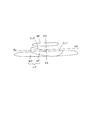
前記ランプユニット1は、図1に示すように、リフレクタ2と、半導体型光源3と、ヒートシンク部材4と、から構成されている。前記リフレクタ2は、たとえば、光不透過性の樹脂などから構成されている。前記リフレクタ2は、図1および図2に示すように、楕円部5と、放物線部6と、傾斜部7と、水平部8と、から一体に構成されている。
As shown in FIG. 1, the
前記楕円部5は、回転楕円形状のものを長軸方向と短軸方向とに4分割した形状をなし、長軸方向の第1開口部9と短軸方向の第2開口部10とを有する。前記楕円部5の前記第1開口部9の縁には、前記傾斜部7が一体に設けられている。前記傾斜部7の一縁(上縁)には、前記水平部8の一縁(前縁)が一体に設けられている。前記水平部8の他縁(後縁)には、前記放物線部6の一縁(下縁)が一体に設けられている。前記楕円部5は、前記放物線部6に対して、前方斜め下側に位置する。前記放物線部6は、前記楕円部5の前記第2開口部10に対向する。前記傾斜部7は、前記水平部8に対して、一縁(上縁)が前記ランプユニット1の光の照射方向と反対方向側(後側)に、かつ、他縁(下縁)が前記ランプユニット1の光の照射方向側(前側)に、傾斜している。前記水平部8は、水平軸H−Hと平行(ほぼ平行も含む)である。
The
前記リフレクタ2には、第1反射面11および第2反射面12および第3反射面13および第4反射面14および第5反射面15およびシェード16およびシェード反射面17などの光学部品が一体に構成されている。すなわち、前記楕円部5の前記第1開口部9および前記第2開口部10に対向する内面には、アルミ蒸着もしくは銀塗装などが施されていて前記第1反射面11が一体に形成されている。前記放物線部6の前記第2開口部10および前記第1反射面11と対向する内面には、アルミ蒸着もしくは銀塗装などが施されていて前記第2反射面12および前記第3反射面13および前記第4反射面14および前記第5反射面15が一体に形成されている。前記傾斜部7の一縁(上縁)7には、前記シェード16が一体に形成されている。前記シェード16の前記第2開口部10および前記第1反射面11および前記第2反射面12および前記第3反射面13および前記第4反射面14と対向する面には、アルミ蒸着もしくは銀塗装などが施されていて前記シェード反射面17が一体に形成されている。
Optical components such as the first reflecting
前記半導体型光源3は、たとえば、LED、EL(有機EL)などの自発光半導体型光源(この実施例ではLED)を使用する。前記半導体型光源3は、図2に示すように、基板18と、前記基板18の一面に設けられている光源チップ19と、前記光源チップ19を覆う半球形状(ドーム形状)の光透過部材(レンズ)20と、からなるものである。前記光源チップ19は、この例では、長方形形状をなす。
As the semiconductor-
前記半導体型光源3は、ホルダ21を介してスクリュー22により前記ヒートシンク部材4に固定されている。また、前記リフレクタ2の前記傾斜部7は、スクリュー23により前記ヒートシンク部材4に固定されている。この結果、前記ランプユニット1が構成される。このとき、前記リフレクタ2の前記楕円部5の前記第1開口部9は、前記ヒートシンク部材4により閉塞されている。また、前記リフレクタ2の前記楕円部5の前記第1反射面11は、前記半導体型光源3に対向する。さらに、前記半導体型光源3の長方形形状の前記光源チップ19は、水平軸(車両の進行軸)H−Hに対して直交(ほぼ直交も含む)である。すなわち、前記半導体型光源3は、横差バルブ(円柱形状のフィラメントが水平軸(車両の進行軸)H−Hに対して直交(ほぼ直交も含む)であるバルブ)と同様な構成となる。なお、図1において、前記リフレクタ2を前記ヒートシンク部材4に固定するスクリュー23は、2本図示されていて、2本図示が省略されている。
The
前記第1反射面11は、楕円反射面である。楕円反射面は、楕円を基調(基本、基準)とする自由曲面からなる反射面、あるいは、回転楕円面からなる反射面である。楕円を基調(基本、基準)とする自由曲面からなる反射面は、図2の垂直断面が楕円をなし、かつ、図示しない水平断面が放物線ないし変形放物線ないし変形楕円ないしそれらの組み合わせからなる反射面である。この結果、楕円反射面である前記第1反射面11は、光軸Z1−Z1と、第1焦点F11と、第2焦点(もしくは第2焦線)F12と、を有する。図2に示すように、前記第1反射面11の光軸Z1−Z1は、側面から見て、水平軸H−Hに対して傾斜している。前記第1焦点F11は、前記第2焦点F12に対して、前方斜め下側に位置する。前記半導体型光源3の前記光源チップ19は、前記第1反射面11の第1焦点F11もしくはその近傍に位置する。この結果、前記半導体型光源3の前記光源チップ19から放射される光の大部分L1は、前記第1反射面11で反射されて前記第1反射面11の第2焦点F12もしくはその近傍に収束する(集まる)。
The first
前記第2反射面12および前記第3反射面13および前記第4反射面14および前記第5反射面15は、放物線反射面である。放物線反射面は、放物線を基調(基本、基準)とする自由曲面からなる反射面、あるいは、回転放物面からなる反射面である。放物線を基調(基本、基準)とする自由曲面からなる反射面は、図2の垂直断面が放物線をなし、かつ、図示しない水平断面が楕円ないし変形楕円ないし変形放物線ないしそれらの組み合わせからなる反射面である。この結果、放物線反射面である前記第2反射面12および前記第3反射面13および前記第4反射面14および前記第5反射面15は、光軸Z2−Z2、Z3−Z3、Z4−Z4、Z5−Z5と、焦点(焦線)F2、F3、F4、F5と、を有する。図2に示すように、前記第2反射面12および前記第3反射面13および前記第4反射面14および前記第5反射面15の光軸Z2−Z2、Z3−Z3、Z4−Z4、Z5−Z5は、側面から見て、水平軸H−Hと平行(ほぼ平行も含む)である。前記第2反射面12および前記第3反射面13および前記第4反射面14の焦点F2、F3、F4は、前記第1反射面11の第2焦点F12もしくはその近傍に位置する。前記第5反射面15の焦点F5は、前記第1反射面11の第1焦点F11もしくはその近傍に位置する。
The second reflecting
前記第1反射面11は、前記第2反射面12および前記第3反射面13および第4反射面14および前記第5反射面15に対して前方斜め下側に位置する。前記第1反射面11および前記半導体型光源3側と前記第2反射面12および前記第3反射面13および第4反射面14および前記第5反射面15側との間には、前記第1反射面11からの反射光および前記半導体型光源3からの直射光を前記第2反射面12および前記第3反射面13および第4反射面14および前記第5反射面15に通すための開口部、すなわち、前記第2開口部10が設けられている。
The first reflecting
前記シェード16は、前記第1反射面11からの反射光L2の一部L3をカットオフするものである。前記シェード16のエッジ、すなわち、前記傾斜部7と前記水平部8との角部は、配光パターンのカットオフラインの形成に関与する。一方、前記シェード反射面17は、前記シェード16によりカットオフされた前記第1反射面11からの反射光L2の一部L3を前記第2反射面12および前記第3反射面13および第4反射面14側に反射させるものである。
The
前記第2反射面12および前記第3反射面13と、前記第4反射面14と、前記第5反射面15とは、図1および図2に示すように、横に分割されている。前記第2反射面12および前記第3反射面13は、前記第4反射面14の上方に位置する。前記第5反射面15は、前記第2反射面12および前記第3反射面13および前記第4反射面14の上方に位置する。
As shown in FIGS. 1 and 2, the second reflecting
前記第2反射面12と前記第3反射面13とは、図1および図2に示すように、縦に分割されている。前記第2反射面12は、前記第3反射面13に対して、対向車線側(右側)に位置する。
The second reflecting
前記第2反射面12および前記第3反射面13および第4反射面14は、前記第1反射面11からの反射光L2(前記シェード16によりカットオフされなかった前記第1反射面11からの反射光L2)および前記シェード反射面17からの反射光L4(前記シェード16によりカットオフされた前記第1反射面11からの反射光L2の一部L3)を制御して図9に示すすれ違い用配光パターンLPとして路面に反射させる反射面である。前記すれ違い用配光パターンLPの上縁には、水平のカットオフラインCL1および斜めのカットオフラインCL2が形成されている。前記すれ違い用配光パターンLPの水平カットオフラインCL1および斜めカットオフラインCL2は、前記シェード16のエッジおよび前記第2反射面12および前記第3反射面13および第4反射面14により形成される。前記すれ違い用配光パターンLPの水平カットオフラインCL1は、スクリーンの左右水平線HL−HRよりも約0.57°下側に位置する。また、前記すれ違い用配光パターンLPの斜めカットオフラインCL2は、水平カットオフラインCL1のスクリーンの上下垂直線VU−VDから左側に約15〜45°傾斜している。
The
前記第2反射面12は、前記シェード反射面17からの反射光L4を制御して図4に示す高光度用配光パターンHPとして路面に反射させる反射面である。前記高光度用配光パターンHPは、範囲が狭く狭められたスポット状の高光度部を形成して、最高光度を高めるものである。前記高光度用配光パターンHPは、スクリーンの上下垂直線VU−VDから左側であって、前記すれ違い用配光パターンLPの斜めカットオフラインCL2の下側に位置する。
The second reflecting
前記第3反射面13は、前記シェード反射面17からの反射光L4を制御して図4に示す集光用配光パターンSPとして路面に反射させる反射面である。前記集光用配光パターンSPの上縁には、前記の水平のカットオフラインCL1および前記の斜めのカットオフラインCL2が形成されている。前記集光用配光パターンSPの水平カットオフラインCL1および斜めカットオフラインCL2は、前記シェード16のエッジおよび前記第3反射面13により形成される。前記集光用配光パターンSPは、前記高光度用配光パターンHPを包含する。前記高光度用配光パターンHPおよび前記集光用配光パターンSPは、前記すれ違い用配光パターンLPのホットスポットであって、前記すれ違い用配光パターンLPの主な配光規格を満足させるものである。
The third reflecting
前記第4反射面14は、前記第1反射面11からの反射光L2を制御して図6に示す拡散用配光パターンWPとして路面に反射させる反射面である。前記拡散用配光パターンWPの上縁には、前記の水平のカットオフラインCL1が形成されている。前記拡散用配光パターンWPの水平カットオフラインCL1は、前記シェード16のエッジおよび前記第4反射面14により形成される。前記拡散用配光パターンWPは、前記すれ違い用配光パターンLPの水平拡散であって、前記すれ違い用配光パターンLPの商品性を向上させる拡散配光を形成するものである。なお、前記拡散用配光パターンWPの水平カットオフラインCL1を前記集光用配光パターンSPの水平カットオフラインCL1よりも約0.3〜1°下側に設定しても良い。
The fourth reflecting
前記第5反射面15は、図1に示すように、前記第2反射面12および前記第3反射面13および第4反射面14の上方に位置する。前記第5反射面15は、前記半導体型光源3からの光(直射光)L5を制御してオーバーヘッドサイン用配光パターンOPとして反射させる反射面である。前記オーバーヘッドサイン用配光パターンOPは、スクリーンの左右水平線HL−HRよりも上側に位置して、図示していないオーバーヘッドサイン(頭上標識)を照明するものである。
As shown in FIG. 1, the fifth reflecting
放物線反射面は、前記第2反射面12と前記第3反射面13と第4反射面14と前記第5反射面15との4個のセグメントに分割されている。また、前記第2反射面12および前記第3反射面13は、単一のセグメントからなり、一方、第4反射面14および前記第5反射面15は、複数個(この例では3個)のセグメントからなるものである。なお、前記第2反射面12および前記第3反射面13および第4反射面14および前記第5反射面15は、それぞれ、配光特性に応じて、単一のセグメントもしくは複数個のセグメントからなるものであっても良い。
The parabolic reflecting surface is divided into four segments of the second reflecting
この実施例における車両用灯具は、以上のごとき構成からなり、以下、その作用について説明する。 The vehicular lamp in this embodiment is configured as described above, and the operation thereof will be described below.
まず、ランプユニット1の半導体型光源3の光源チップ19を点灯発光させる。すると、半導体型光源3の光源チップ19から放射された光の大部分L1は、第1反射面11に入射する。また、半導体型光源3の光源チップ19から放射された光の一部L5は、直射光としてリフレクタ2の第2開口部10を経て主に第5反射面15に直接入射する。
First, the
第1反射面11に入射した光L1は、第1反射面11で反射する。第1反射面11で反射した反射光L2は、第1反射面11の第2焦点F12もしくはその近傍に収束する(集まる)。第1反射面11からの反射光L2であって、シェード16によりカットオフされなかった第1反射面11からの反射光L2は、リフレクタ2の第2開口部10を経て主に第4反射面14に入射する。また、第1反射面11からの反射光L2であって、シェード16によりカットオフされた第1反射面11からの反射光L2の一部L3は、シェード反射面17で反射する。シェード反射面17からの反射光L4は、リフレクタ2の第2開口部10を経て主に第2反射面12および第3反射面13に入射する。
The light L1 incident on the first reflecting
第2反射面12に入射したシェード反射面17からの反射光L4は、第2反射面12および第3反射面13で反射する。第2反射面12からの反射光は、第2反射面12で、図4に示す高光度用配光パターンHPとして制御されて路面に照射される。第3反射面13からの反射光は、第3反射面13で、図4に示す集光用配光パターンSP、すなわち、上縁に水平カットオフラインCL1および斜めカットオフラインCL2を有し、かつ、高光度用配光パターンHPを包含する集光用配光パターンSPとして制御されて路面に照射される。
The reflected light L4 from the
また、第4反射面14に入射した第1反射面11からの反射光L2は、第4反射面14で反射する。第4反射面14からの反射光は、第4反射面14で、図6に示す拡散用配光パターンWP、すなわち、上縁に水平カットオフラインCL1を有する拡散用配光パターンWPとして制御されて路面に照射される。
Further, the reflected light L <b> 2 from the first reflecting
図4に示す高光度用配光パターンHPおよび集光用配光パターンSPと図6に示す拡散用配光パターンWPとが重畳されて図9に示すすれ違い用配光パターンLP、すなわち、上縁に水平カットオフラインCL1および斜めカットオフラインCL2を有するすれ違い用配光パターンLPが形成される。 The light distribution pattern for high light intensity HP and the light distribution pattern for light collection SP shown in FIG. 4 and the light distribution pattern for diffusion WP shown in FIG. A passing light distribution pattern LP having a horizontal cutoff line CL1 and an oblique cutoff line CL2 is formed.
第5反射面15に直接入射した半導体型光源3の光源チップ19からの直射光L5は、第5反射面15で反射する。第5反射面15からの反射光は、第5反射面15で図8に示すオーバーヘッドサイン用配光パターンOPとして制御されてオーバーヘッドサインに照射される。この結果、図9に示すように、高光度用配光パターンHPおよび集光用配光パターンSPと拡散用配光パターンWPとが重畳されてなるすれ違い用配光パターンLPと、オーバーヘッドサイン用配光パターンOPとが得られる。
The direct light L <b> 5 from the
ここで、1個の半導体型光源3の光束(光度、照度、光量)が大きいと、1個のランプユニット1により、所定の配光特性を有するすれ違い用配光パターンLP(高光度用配光パターンHPおよび集光用配光パターンSPおよび拡散用配光パターンWP)およびオーバーヘッドサイン用配光パターンOPが得られる。
Here, when the luminous flux (luminance, illuminance, light quantity) of one semiconductor-
この実施例における車両用灯具は、以上のごとき構成および作用からなり、以下、その効果について説明する。 The vehicular lamp in this embodiment is configured and operated as described above, and the effects thereof will be described below.
この実施例における車両用灯具(ランプユニット1)は、第2反射面12により高光度部を有する高光度用配光パターンHPが得られ、また、第3反射面13により高光度用配光パターンHPを包含する集光用配光パターンSPが得られ、さらに、第4反射面14により高光度用配光パターンHPおよび集光用配光パターンSPと重畳する拡散用配光パターンWPが得られる。この結果、この実施例における車両用灯具(ランプユニット1)は、1個のランプユニット1で理想のすれ違い用配光パターンLPを得ることができ、交通安全に貢献することができる。
In the vehicle lamp (lamp unit 1) in this embodiment, a high luminous intensity light distribution pattern HP having a high luminous intensity portion is obtained by the second
また、この実施例における車両用灯具(ランプユニット1)は、第2反射面12が第3反射面13に対して対向車線側(右側)に位置するので、集光用配光パターンSP中に包含されている高光度用配光パターンHPを走行車線側(左側)すなわちスクリーンの上下垂直線VU−VDの左側に簡単な配光設計、たとえば、図10に示すように、平面(上面)から見て、第2反射面12の光軸Z2−Z2を走行車線側(左側)すなわち水平軸(車両の進行軸)H−Hに対して左側に振り向けるなどの配光設計で配光することができる。しかも、この実施例における車両用灯具(ランプユニット1)は、集光用配光パターンSP中の高光度用配光パターンHPを走行車線側(左側)に配光することができるので、走行車線側の視認性が向上されて、交通安全にさらに貢献することができる。特に、この実施例における車両用灯具(ランプユニット1)は、第2反射面12および第3反射面13が第4反射面14に対して上方に位置するので、高光度用配光パターンHPおよび集光用配光パターンSPを拡散用配光パターンWPよりも上方に位置させることができるので、1個のランプユニット1で理想のすれ違い用配光パターンLPを得ることができ、交通安全に貢献することができる。
Further, in the vehicle lamp (lamp unit 1) in this embodiment, the second reflecting
さらに、この実施例における車両用灯具(ランプユニット1)は、第1反射面11からの反射光L2の一部L3をシェード16でカットオフするので、第2反射面12および第3反射面13および第4反射面14でカットオフラインCL1、CL2を有するすれ違い用配光パターンLPを容易に制御することができる。しかも、この実施例における車両用灯具(ランプユニット1)は、シェード16によりカットオフされた第1反射面11からの反射光L2の一部L3をシェード用反射面17で第2反射面12および第3反射面13に反射させるので、半導体型光源3から放射される光L1を有効に利用することができる。これにより、この実施例における車両用灯具(ランプユニット1)は、1個のランプユニット1で理想のすれ違い用配光パターンLPを得ることができ、交通安全に貢献することができる。
Furthermore, since the vehicle lamp (lamp unit 1) in this embodiment cuts off part L3 of the reflected light L2 from the first reflecting
さらにまた、この実施例における車両用灯具(ランプユニット1)は、オーバーヘッドサイン用放物線反射面の第5反射面15が第2反射面12および第3反射面13および第4反射面14の上方に位置するので、第5反射面15が半導体型光源3からの光L5を図8に示すオーバーヘッドサイン用配光パターンOPとして制御するのに適している。これにより、この実施例における車両用灯具(ランプユニット1)は、1個のランプユニット1で理想のすれ違い用配光パターンLPおよびオーバーヘッドサイン用配光パターンOPを得ることができ、交通安全に貢献することができる。
Furthermore, in the vehicle lamp (lamp unit 1) in this embodiment, the fifth reflecting
以下、前記の実施例以外の例について説明する。前記の実施例においては、放物線反射面の第2反射面12および第3反射面13および第4反射面14ですれ違い用配光パターンLP(高光度用配光パターンHPおよび集光用配光パターンSPおよび拡散用配光パターンWP)を形成するものである。ところが、この発明においては、放物線反射面の第2反射面12および第3反射面13および第4反射面14で形成する所定の配光パターンとしては、すれ違い用配光パターンLP以外の配光パターン、たとえば、走行用配光パターン、高速道路用配光パターン、フォグランプ(霧)用配光パターン、雨用配光パターン、追加灯用配光パターンなどであっても良い。
Hereinafter, examples other than the above-described embodiment will be described. In the above-described embodiment, the light distribution pattern LP for passing through the
また、前記の実施例においては、第2反射面12を第3反射面13に対して対向車線側(右側)に位置させたものである。ところが、この発明においては、第2反射面12を第3反射面13に対して対向車線側(右側)に位置させなくても良い。
Further, in the above-described embodiment, the second reflecting
さらに、前記の実施例においては、第2反射面12および第3反射面13を第4反射面14の上方に位置させたものである。ところが、この発明においては、第2反射面12および第3反射面13を第4反射面14の上方に位置させなくても良い。
Furthermore, in the above-described embodiment, the second reflecting
さらにまた、前記の実施例においては、シェード16を設け、また、シェード16にシェード反射面17を設けたものである。ところが、この発明においては、シェード16を設けずに、また、シェード16にシェード反射面17を設けなくても良い。
Furthermore, in the above-described embodiment, the
さらにまた、前記の実施例においては、第2反射面12および第3反射面13および第4反射面14の上方にオーバーヘッドサイン用放物面反射面の第5反射面15を設けたものである。ところが、この発明においては、第2反射面12および第3反射面13および第4反射面14の上方に第5反射面15を設けず、オーバーヘッドサイン用配光パターンOPを形成しなくても良い。
Furthermore, in the above-described embodiment, the fifth reflecting
1 ランプユニット(車両用灯具)
2 リフレクタ
3 半導体型光源
4 ヒートシンク部材
5 楕円部
6 放物線部
7 傾斜部
8 水平部
9 第1開口部
10 第2開口部
11 第1反射面(楕円反射面)
12 第2反射面(放物線反射面)
13 第3反射面(放物線反射面)
14 第4反射面(放物線反射面)
15 第5反射面(オーバーヘッドサイン用放物線反射面)
16 シェード
17 シェード反射面
18 基板
19 光源チップ
20 光透過部材
21 ホルダ
22 スクリュー
23 スクリュー
F 前
B 後
U 上
D 下
L 左
R 右
HL−HR スクリーンの左右の水平線
VU−VD スクリーンの上下の垂直線
H−H 水平軸(車両の進行軸)
Z1−Z1 第1反射面の光軸
F11 第1反射面の第1焦点
F12 第1反射面の第2焦点
Z2−Z2 第2反射面の光軸
F2 第2反射面の焦点
Z3−Z3 第3反射面の光軸
F3 第3反射面の焦点
Z4−Z4 第4反射面の光軸
F4 第4反射面の焦点
Z5−Z5 第5反射面の光軸
F5 第5反射面の焦点
LP すれ違い用の配光パターン
CL1 水平カットライン
CL2 斜めカットライン
HP 高光度用配光パターン
SP 集光用配光パターン
WP 拡散用配光パターン
OP オーバーヘッドサイン用配光パターン
L1 半導体型光源からの光の大部分
L2 シェードでカットオフされない第1反射面からの反射光
L3 シェードでカットオフされる第1反射面からの反射光
L4 シェード反射面からの反射光
L5 半導体型光源からの直射光
1 Lamp unit (vehicle lamp)
DESCRIPTION OF
12 Second reflective surface (parabolic reflective surface)
13 Third reflective surface (parabolic reflective surface)
14 4th reflective surface (parabolic reflective surface)
15 Fifth reflective surface (parabolic reflective surface for overhead sign)
16
Z1-Z1 Optical axis of the first reflecting surface F11 First focal point of the first reflecting surface F12 Second focal point of the first reflecting surface Z2-Z2 Optical axis of the second reflecting surface F2 Focal point of the second reflecting surface Z3-Z3 Third Optical axis of the reflecting surface F3 Focus of the third reflecting surface Z4-Z4 Optical axis of the fourth reflecting surface F4 Focus of the fourth reflecting surface Z5-Z5 Optical axis of the fifth reflecting surface F5 Focus of the fifth reflecting surface LP For passing Light distribution pattern CL1 Horizontal cut line CL2 Diagonal cut line HP Light distribution pattern for high intensity SP Light distribution pattern for condensing WP Light distribution pattern for diffusion OP Light distribution pattern for overhead sign L1 Most of light from semiconductor light source L2 Shade Reflected light from the first reflecting surface not cut off by L3 Reflected light from the first reflecting surface cut off by the shade L4 Reflected light from the shade reflecting surface L5 Direct light from the semiconductor-type light source
Claims (4)
楕円反射面の第1反射面と、
前記第1反射面の第1焦点もしくはその近傍に配置されている前記半導体型光源と、
前記第1反射面からの反射光を制御して高光度部を有する高光度用配光パターンとして路面に反射させる放物線反射面の第2反射面と、
前記第1反射面からの反射光を制御して前記高光度用配光パターンを包含する集光用配光パターンとして路面に反射させる放物線反射面の第3反射面と、
前記第1反射面からの反射光を制御して前記高光度用配光パターンおよび前記集光用配光パターンと重畳する拡散用配光パターンとして路面に反射させる放物線反射面の第4反射面と、
を備える、ことを特徴とする車両用灯具。 In a vehicle lamp having a semiconductor-type light source as a light source and having a plurality of reflecting surfaces,
A first reflective surface of an elliptical reflective surface;
The semiconductor-type light source disposed at or near the first focal point of the first reflecting surface;
A second reflecting surface of a parabolic reflecting surface that controls reflected light from the first reflecting surface and reflects it to a road surface as a high luminous intensity light distribution pattern having a high luminous intensity portion;
A third reflecting surface of a parabolic reflecting surface that reflects reflected light from the first reflecting surface to the road surface as a condensing light distribution pattern including the high light intensity light distribution pattern;
A fourth reflecting surface of a parabolic reflecting surface that controls reflected light from the first reflecting surface and reflects it to the road surface as a diffusion light distribution pattern that overlaps the light distribution pattern for high luminous intensity and the light distribution pattern for condensing light; ,
A vehicular lamp characterized by comprising:
前記第2反射面および前記第3反射面は、前記第4反射面に対して、上方に位置する、
ことを特徴とする請求項1に記載の車両用灯具。 The second reflective surface is located on the opposite lane side with respect to the third reflective surface,
The second reflective surface and the third reflective surface are located above the fourth reflective surface;
The vehicular lamp according to claim 1.
前記シェードには、前記シェードによりカットオフされた前記第1反射面からの反射光の一部を前記第2反射面および前記第3反射面に反射させるシェード反射面が設けられていて、
前記第2反射面および前記第3反射面および前記第4反射面は、焦点が前記第1反射面の第2焦点もしくはその近傍に位置していて、前記第1反射面からの反射光および前記シェード反射面からの反射光を制御してすれ違い用配光パターンとして路面に反射させる反射面である、
ことを特徴とする請求項1または2に記載の車両用灯具。 A shade that cuts off part of the reflected light from the first reflecting surface is provided at or near the second focal point of the first reflecting surface,
The shade is provided with a shade reflection surface that reflects a part of reflected light from the first reflection surface cut off by the shade to the second reflection surface and the third reflection surface,
The second reflecting surface, the third reflecting surface, and the fourth reflecting surface have a focal point located at or near the second focal point of the first reflecting surface, and the reflected light from the first reflecting surface and the It is a reflecting surface that reflects the light reflected from the shade reflecting surface to the road surface as a passing light distribution pattern.
The vehicular lamp according to claim 1 or 2.
ことを特徴とする請求項3に記載の車両用灯具。 Above the second reflecting surface, the third reflecting surface, and the fourth reflecting surface, a focal point is positioned at or near the semiconductor-type light source, and the light from the semiconductor-type light source is controlled to provide an overhead sign. A parabolic reflecting surface for overhead sign to be reflected as a light distribution pattern is provided.
The vehicular lamp according to claim 3.
Priority Applications (5)
| Application Number | Priority Date | Filing Date | Title |
|---|---|---|---|
| JP2008127098A JP4582190B2 (en) | 2008-05-14 | 2008-05-14 | Vehicle lighting |
| CN2009100080857A CN101581428B (en) | 2008-05-14 | 2009-03-03 | Lamp for vehicle |
| AT09160097T ATE519070T1 (en) | 2008-05-14 | 2009-05-13 | LAMP FOR A VEHICLE |
| EP09160097A EP2119958B1 (en) | 2008-05-14 | 2009-05-13 | Lamp for vehicle |
| US12/465,296 US8197109B2 (en) | 2008-05-14 | 2009-05-13 | Lamp for vehicle |
Applications Claiming Priority (1)
| Application Number | Priority Date | Filing Date | Title |
|---|---|---|---|
| JP2008127098A JP4582190B2 (en) | 2008-05-14 | 2008-05-14 | Vehicle lighting |
Publications (2)
| Publication Number | Publication Date |
|---|---|
| JP2009277481A JP2009277481A (en) | 2009-11-26 |
| JP4582190B2 true JP4582190B2 (en) | 2010-11-17 |
Family
ID=40791409
Family Applications (1)
| Application Number | Title | Priority Date | Filing Date |
|---|---|---|---|
| JP2008127098A Active JP4582190B2 (en) | 2008-05-14 | 2008-05-14 | Vehicle lighting |
Country Status (5)
| Country | Link |
|---|---|
| US (1) | US8197109B2 (en) |
| EP (1) | EP2119958B1 (en) |
| JP (1) | JP4582190B2 (en) |
| CN (1) | CN101581428B (en) |
| AT (1) | ATE519070T1 (en) |
Families Citing this family (38)
| Publication number | Priority date | Publication date | Assignee | Title |
|---|---|---|---|---|
| JP5442350B2 (en) * | 2009-07-27 | 2014-03-12 | 株式会社小糸製作所 | Vehicle lighting |
| JP5471596B2 (en) * | 2010-03-01 | 2014-04-16 | 市光工業株式会社 | Vehicle lighting |
| CN103109131B (en) * | 2010-07-26 | 2016-03-09 | 法雷奥照明公司 | For the illumination of motor vehicles and/or the optical module of recoil simulator |
| CN101956954B (en) * | 2010-09-30 | 2013-10-02 | 海洋王照明科技股份有限公司 | Automobile headlight and reflector used for same |
| CN102043239B (en) * | 2010-10-26 | 2013-03-06 | 张德胜 | Quadruple parabolic cylinder condenser |
| CN102486298B (en) * | 2010-12-06 | 2013-10-16 | 海洋王照明科技股份有限公司 | Reflector of front fog lamp, front fog lamp and motor vehicle |
| CN102486296B (en) * | 2010-12-06 | 2013-09-04 | 海洋王照明科技股份有限公司 | Reflector of front fog lamp, front fog lamp and motor vehicle |
| JP5643630B2 (en) | 2010-12-14 | 2014-12-17 | 株式会社小糸製作所 | Lighting fixtures for vehicles |
| TWI507637B (en) * | 2011-01-27 | 2015-11-11 | B&M Optics Co Ltd | Light guide module and lighting device having the same |
| US9689546B2 (en) | 2011-03-25 | 2017-06-27 | Light Prescriptions Innovators, Llc | Vehicle lighting unit |
| JP5707661B2 (en) * | 2011-03-25 | 2015-04-30 | スタンレー電気株式会社 | VEHICLE LIGHT UNIT AND LIGHT GUIDE USED FOR VEHICLE LIGHT |
| DE102011006380A1 (en) * | 2011-03-29 | 2012-10-04 | Automotive Lighting Reutlingen Gmbh | Motor vehicle headlight with a semiconductor light source |
| US8545072B2 (en) * | 2011-05-03 | 2013-10-01 | Osram Sylvania Inc. | Optic emitting a simulated floating band of light |
| US8740424B2 (en) | 2011-05-20 | 2014-06-03 | Goodrich Lighting Systems Gmbh | Light for an aircraft |
| JP5913954B2 (en) * | 2011-12-16 | 2016-05-11 | スタンレー電気株式会社 | Reflector for vehicle lamp |
| DE102012003071B4 (en) * | 2012-02-10 | 2014-11-20 | Alfred-Wegener-Institut Helmholtz-Zentrum für Polar- und Meeresforschung | reflector spotlight |
| DE102012202933A1 (en) * | 2012-02-27 | 2013-08-29 | Osram Gmbh | lighting device |
| WO2014119980A1 (en) * | 2013-01-30 | 2014-08-07 | Terán Balaguer Luis Fausto | Device for front lighting with adaptive light patterns |
| DE102013206488A1 (en) * | 2013-04-11 | 2014-10-30 | Automotive Lighting Reutlingen Gmbh | Light module for a motor vehicle lighting device |
| JP6186844B2 (en) * | 2013-04-25 | 2017-08-30 | 市光工業株式会社 | Vehicle lighting |
| DE102013207845A1 (en) * | 2013-04-29 | 2014-10-30 | Automotive Lighting Reutlingen Gmbh | Light module for a motor vehicle headlight |
| US9416933B2 (en) | 2013-09-27 | 2016-08-16 | Valeo North America, Inc. | Multi-function LED headlamp |
| FR3022010B1 (en) * | 2014-03-21 | 2019-04-05 | Valeo Iluminacion | LUMINOUS MODULE OF A MOTOR VEHICLE |
| MX341222B (en) | 2014-03-24 | 2016-08-11 | Magneti Marelli Spa | Vehicle instrument panel equipped with a led backlighting device for lighting a graphic area. |
| US10697607B2 (en) | 2014-06-08 | 2020-06-30 | Valeo North America, Inc. | Thin aspect lighting system with cutoff |
| WO2016024489A1 (en) | 2014-08-11 | 2016-02-18 | 株式会社小糸製作所 | Vehicle headlight |
| JP6439341B2 (en) * | 2014-09-18 | 2018-12-19 | 市光工業株式会社 | Vehicle lighting |
| FR3039883B1 (en) * | 2015-08-06 | 2020-10-02 | Valeo Vision | LUMINOUS MODULE IN TRANSPARENT MATERIAL WITH TWO SIDES OF REFLECTION |
| US9931977B2 (en) * | 2015-11-27 | 2018-04-03 | Sl Corporation | Vehicle lamp |
| TWM537997U (en) * | 2016-11-18 | 2017-03-11 | Sun Yujing Tech Ltd | Modularized lens vehicle lamp capable of enhancing illumination intensity |
| KR101937976B1 (en) * | 2016-12-27 | 2019-01-14 | 에스엘 주식회사 | Lamp for vehicle |
| US10234101B2 (en) * | 2017-04-27 | 2019-03-19 | Hyundai Mobis Co., Ltd. | Optical device |
| FR3077367B1 (en) * | 2018-01-31 | 2021-04-16 | Valeo Vision | DUAL-FUNCTION LIGHT MODULE WITH COMMON ILLUMINATED SURFACE |
| KR102072436B1 (en) * | 2019-04-26 | 2020-02-03 | 안유근 | Lamp apparatus for automobile |
| EP3772610B1 (en) | 2019-08-06 | 2022-04-20 | Nichia Corporation | Lighting device |
| FR3118120B1 (en) * | 2020-12-18 | 2023-05-05 | Valeo Vison Service Ip | Automotive headlamp with several lighting modules on a common inclined plate. |
| KR20230028924A (en) * | 2021-08-23 | 2023-03-03 | 현대모비스 주식회사 | Lamp for vehicle and vehicle including the same |
| TWI786003B (en) * | 2022-03-16 | 2022-12-01 | 堤維西交通工業股份有限公司 | Virtual focus type side light headlight device |
Citations (9)
| Publication number | Priority date | Publication date | Assignee | Title |
|---|---|---|---|---|
| JPH1031904A (en) * | 1996-07-17 | 1998-02-03 | Koito Mfg Co Ltd | Headlight of vehicle |
| JP2002324413A (en) * | 2001-04-24 | 2002-11-08 | Koito Mfg Co Ltd | Head light for vehicle |
| JP2003331617A (en) * | 2002-05-13 | 2003-11-21 | Stanley Electric Co Ltd | Vehicular lighting fixture |
| JP2005135918A (en) * | 2003-10-31 | 2005-05-26 | Valeo Vision | Vehicular headlamp with light source formed of discharge lamp |
| JP2005166371A (en) * | 2003-12-01 | 2005-06-23 | Ichikoh Ind Ltd | Lighting fixture for vehicle |
| JP2005302603A (en) * | 2004-04-14 | 2005-10-27 | Ichikoh Ind Ltd | Vehicular headlight unit |
| JP2006019051A (en) * | 2004-06-30 | 2006-01-19 | Ichikoh Ind Ltd | Vehicular lighting fixture |
| JP2006019052A (en) * | 2004-06-30 | 2006-01-19 | Ichikoh Ind Ltd | Vehicular lighting fixture |
| JP2008041557A (en) * | 2006-08-09 | 2008-02-21 | Ichikoh Ind Ltd | Lamp unit for vehicle headlight |
Family Cites Families (5)
| Publication number | Priority date | Publication date | Assignee | Title |
|---|---|---|---|---|
| US5055981A (en) * | 1989-02-17 | 1991-10-08 | Koito Manufacturing Co., Ltd. | Automotive projector type headlight |
| JP4536479B2 (en) * | 2003-12-02 | 2010-09-01 | 株式会社小糸製作所 | Vehicle headlamp |
| JP2006127856A (en) * | 2004-10-27 | 2006-05-18 | Koito Mfg Co Ltd | Vehicular lighting lamp |
| JP2006156045A (en) * | 2004-11-26 | 2006-06-15 | Koito Mfg Co Ltd | Vehicular headlight |
| JP2008171743A (en) * | 2007-01-15 | 2008-07-24 | Koito Mfg Co Ltd | Headlamp for vehicle |
-
2008
- 2008-05-14 JP JP2008127098A patent/JP4582190B2/en active Active
-
2009
- 2009-03-03 CN CN2009100080857A patent/CN101581428B/en active Active
- 2009-05-13 US US12/465,296 patent/US8197109B2/en active Active
- 2009-05-13 AT AT09160097T patent/ATE519070T1/en not_active IP Right Cessation
- 2009-05-13 EP EP09160097A patent/EP2119958B1/en not_active Not-in-force
Patent Citations (9)
| Publication number | Priority date | Publication date | Assignee | Title |
|---|---|---|---|---|
| JPH1031904A (en) * | 1996-07-17 | 1998-02-03 | Koito Mfg Co Ltd | Headlight of vehicle |
| JP2002324413A (en) * | 2001-04-24 | 2002-11-08 | Koito Mfg Co Ltd | Head light for vehicle |
| JP2003331617A (en) * | 2002-05-13 | 2003-11-21 | Stanley Electric Co Ltd | Vehicular lighting fixture |
| JP2005135918A (en) * | 2003-10-31 | 2005-05-26 | Valeo Vision | Vehicular headlamp with light source formed of discharge lamp |
| JP2005166371A (en) * | 2003-12-01 | 2005-06-23 | Ichikoh Ind Ltd | Lighting fixture for vehicle |
| JP2005302603A (en) * | 2004-04-14 | 2005-10-27 | Ichikoh Ind Ltd | Vehicular headlight unit |
| JP2006019051A (en) * | 2004-06-30 | 2006-01-19 | Ichikoh Ind Ltd | Vehicular lighting fixture |
| JP2006019052A (en) * | 2004-06-30 | 2006-01-19 | Ichikoh Ind Ltd | Vehicular lighting fixture |
| JP2008041557A (en) * | 2006-08-09 | 2008-02-21 | Ichikoh Ind Ltd | Lamp unit for vehicle headlight |
Also Published As
| Publication number | Publication date |
|---|---|
| US8197109B2 (en) | 2012-06-12 |
| EP2119958B1 (en) | 2011-08-03 |
| US20090284980A1 (en) | 2009-11-19 |
| CN101581428A (en) | 2009-11-18 |
| JP2009277481A (en) | 2009-11-26 |
| EP2119958A1 (en) | 2009-11-18 |
| ATE519070T1 (en) | 2011-08-15 |
| CN101581428B (en) | 2010-12-22 |
Similar Documents
| Publication | Publication Date | Title |
|---|---|---|
| JP4582190B2 (en) | Vehicle lighting | |
| JP4735664B2 (en) | Vehicle lighting | |
| US7059755B2 (en) | Vehicle lamp | |
| KR100570480B1 (en) | Vehicle headlamp | |
| JP5818134B2 (en) | Vehicle headlamp | |
| JP5352263B2 (en) | Vehicle lighting | |
| JP5146214B2 (en) | Vehicle lighting | |
| JP2009277482A (en) | Lighting fixture for vehicle | |
| US8678629B2 (en) | Lamp unit for vehicular headlamp | |
| JP2005150041A (en) | Lighting fixture | |
| JP2004095481A (en) | Head light for vehicle | |
| JP2004095479A (en) | Headlight for vehicle | |
| JP2008041557A (en) | Lamp unit for vehicle headlight | |
| JP5041307B2 (en) | Vehicle headlamp | |
| JP2010140891A (en) | Vehicle headlamp | |
| JP4407395B2 (en) | Vehicle lighting | |
| JP5468876B2 (en) | Optical unit | |
| JP5266607B2 (en) | Vehicle headlamp | |
| JP4781451B2 (en) | LED light source for vehicular lamp | |
| JP2007172882A (en) | Vehicle headlight | |
| JP2011238524A (en) | Vehicular headlight | |
| JP5251209B2 (en) | Reflective lamp unit for vehicles using semiconductor light source | |
| JP5196277B2 (en) | Vehicle headlamp | |
| JP2006185606A (en) | Vehicular lighting fixture |
Legal Events
| Date | Code | Title | Description |
|---|---|---|---|
| A621 | Written request for application examination |
Free format text: JAPANESE INTERMEDIATE CODE: A621 Effective date: 20100407 |
|
| A977 | Report on retrieval |
Free format text: JAPANESE INTERMEDIATE CODE: A971007 Effective date: 20100729 |
|
| TRDD | Decision of grant or rejection written | ||
| A01 | Written decision to grant a patent or to grant a registration (utility model) |
Free format text: JAPANESE INTERMEDIATE CODE: A01 Effective date: 20100803 |
|
| A01 | Written decision to grant a patent or to grant a registration (utility model) |
Free format text: JAPANESE INTERMEDIATE CODE: A01 |
|
| A61 | First payment of annual fees (during grant procedure) |
Free format text: JAPANESE INTERMEDIATE CODE: A61 Effective date: 20100816 |
|
| R150 | Certificate of patent or registration of utility model |
Ref document number: 4582190 Country of ref document: JP Free format text: JAPANESE INTERMEDIATE CODE: R150 Free format text: JAPANESE INTERMEDIATE CODE: R150 |
|
| FPAY | Renewal fee payment (event date is renewal date of database) |
Free format text: PAYMENT UNTIL: 20130910 Year of fee payment: 3 |
|
| FPAY | Renewal fee payment (event date is renewal date of database) |
Free format text: PAYMENT UNTIL: 20130910 Year of fee payment: 3 |
|
| R250 | Receipt of annual fees |
Free format text: JAPANESE INTERMEDIATE CODE: R250 |
|
| R250 | Receipt of annual fees |
Free format text: JAPANESE INTERMEDIATE CODE: R250 |
|
| R250 | Receipt of annual fees |
Free format text: JAPANESE INTERMEDIATE CODE: R250 |
|
| R250 | Receipt of annual fees |
Free format text: JAPANESE INTERMEDIATE CODE: R250 |
|
| R250 | Receipt of annual fees |
Free format text: JAPANESE INTERMEDIATE CODE: R250 |
|
| R250 | Receipt of annual fees |
Free format text: JAPANESE INTERMEDIATE CODE: R250 |
|
| R250 | Receipt of annual fees |
Free format text: JAPANESE INTERMEDIATE CODE: R250 |
|
| R250 | Receipt of annual fees |
Free format text: JAPANESE INTERMEDIATE CODE: R250 |
|
| R250 | Receipt of annual fees |
Free format text: JAPANESE INTERMEDIATE CODE: R250 |
|
| R250 | Receipt of annual fees |
Free format text: JAPANESE INTERMEDIATE CODE: R250 |
|
| R250 | Receipt of annual fees |
Free format text: JAPANESE INTERMEDIATE CODE: R250 |