EP2789900B1 - Light module for a motor vehicle lighting device - Google Patents
Light module for a motor vehicle lighting device Download PDFInfo
- Publication number
- EP2789900B1 EP2789900B1 EP14160764.8A EP14160764A EP2789900B1 EP 2789900 B1 EP2789900 B1 EP 2789900B1 EP 14160764 A EP14160764 A EP 14160764A EP 2789900 B1 EP2789900 B1 EP 2789900B1
- Authority
- EP
- European Patent Office
- Prior art keywords
- light
- reflector
- light module
- array
- module
- Prior art date
- Legal status (The legal status is an assumption and is not a legal conclusion. Google has not performed a legal analysis and makes no representation as to the accuracy of the status listed.)
- Active
Links
- 238000009826 distribution Methods 0.000 claims description 57
- 239000006185 dispersion Substances 0.000 claims description 6
- 230000001154 acute effect Effects 0.000 claims description 4
- 230000004075 alteration Effects 0.000 claims description 3
- 206010010071 Coma Diseases 0.000 claims description 2
- 230000003287 optical effect Effects 0.000 description 45
- 239000004065 semiconductor Substances 0.000 description 15
- 239000011521 glass Substances 0.000 description 6
- 238000003384 imaging method Methods 0.000 description 6
- 229910052751 metal Inorganic materials 0.000 description 6
- 239000002184 metal Substances 0.000 description 6
- 229920002492 poly(sulfone) Polymers 0.000 description 5
- 229920000089 Cyclic olefin copolymer Polymers 0.000 description 4
- PXHVJJICTQNCMI-UHFFFAOYSA-N Nickel Chemical compound [Ni] PXHVJJICTQNCMI-UHFFFAOYSA-N 0.000 description 4
- 238000005286 illumination Methods 0.000 description 4
- 229920003229 poly(methyl methacrylate) Polymers 0.000 description 4
- 239000004926 polymethyl methacrylate Substances 0.000 description 4
- 230000005855 radiation Effects 0.000 description 4
- 238000007493 shaping process Methods 0.000 description 4
- 229920002379 silicone rubber Polymers 0.000 description 4
- 239000003550 marker Substances 0.000 description 3
- 239000011159 matrix material Substances 0.000 description 3
- 238000001465 metallisation Methods 0.000 description 3
- 239000004033 plastic Substances 0.000 description 3
- 229920003023 plastic Polymers 0.000 description 3
- 239000004417 polycarbonate Substances 0.000 description 3
- 229920000515 polycarbonate Polymers 0.000 description 3
- 239000004945 silicone rubber Substances 0.000 description 3
- 241001136792 Alle Species 0.000 description 2
- -1 COC Polymers 0.000 description 2
- RYGMFSIKBFXOCR-UHFFFAOYSA-N Copper Chemical compound [Cu] RYGMFSIKBFXOCR-UHFFFAOYSA-N 0.000 description 2
- 238000003491 array Methods 0.000 description 2
- 239000011248 coating agent Substances 0.000 description 2
- 238000000576 coating method Methods 0.000 description 2
- 229910052802 copper Inorganic materials 0.000 description 2
- 239000010949 copper Substances 0.000 description 2
- 239000000835 fiber Substances 0.000 description 2
- 238000009434 installation Methods 0.000 description 2
- 239000000463 material Substances 0.000 description 2
- 229910052759 nickel Inorganic materials 0.000 description 2
- 239000013307 optical fiber Substances 0.000 description 2
- BASFCYQUMIYNBI-UHFFFAOYSA-N platinum Chemical compound [Pt] BASFCYQUMIYNBI-UHFFFAOYSA-N 0.000 description 2
- 210000001747 pupil Anatomy 0.000 description 2
- 208000008918 voyeurism Diseases 0.000 description 2
- VYZAMTAEIAYCRO-UHFFFAOYSA-N Chromium Chemical compound [Cr] VYZAMTAEIAYCRO-UHFFFAOYSA-N 0.000 description 1
- 239000004944 Liquid Silicone Rubber Substances 0.000 description 1
- 239000004696 Poly ether ether ketone Substances 0.000 description 1
- 239000004697 Polyetherimide Substances 0.000 description 1
- BQCADISMDOOEFD-UHFFFAOYSA-N Silver Chemical compound [Ag] BQCADISMDOOEFD-UHFFFAOYSA-N 0.000 description 1
- ATJFFYVFTNAWJD-UHFFFAOYSA-N Tin Chemical compound [Sn] ATJFFYVFTNAWJD-UHFFFAOYSA-N 0.000 description 1
- 230000003213 activating effect Effects 0.000 description 1
- 230000004913 activation Effects 0.000 description 1
- 229910045601 alloy Inorganic materials 0.000 description 1
- 239000000956 alloy Substances 0.000 description 1
- 229910052782 aluminium Inorganic materials 0.000 description 1
- XAGFODPZIPBFFR-UHFFFAOYSA-N aluminium Chemical compound [Al] XAGFODPZIPBFFR-UHFFFAOYSA-N 0.000 description 1
- 238000013459 approach Methods 0.000 description 1
- 230000004888 barrier function Effects 0.000 description 1
- 229910052804 chromium Inorganic materials 0.000 description 1
- 239000011651 chromium Substances 0.000 description 1
- 229920001577 copolymer Polymers 0.000 description 1
- 230000009849 deactivation Effects 0.000 description 1
- PCHJSUWPFVWCPO-UHFFFAOYSA-N gold Chemical compound [Au] PCHJSUWPFVWCPO-UHFFFAOYSA-N 0.000 description 1
- 229910052737 gold Inorganic materials 0.000 description 1
- 239000010931 gold Substances 0.000 description 1
- 238000013507 mapping Methods 0.000 description 1
- 150000002739 metals Chemical class 0.000 description 1
- 210000003733 optic disk Anatomy 0.000 description 1
- 229910052697 platinum Inorganic materials 0.000 description 1
- 229920006162 poly(etherimide sulfone) Polymers 0.000 description 1
- 229920002530 polyetherether ketone Polymers 0.000 description 1
- 229910052709 silver Inorganic materials 0.000 description 1
- 239000004332 silver Substances 0.000 description 1
- 230000006641 stabilisation Effects 0.000 description 1
- 238000011105 stabilization Methods 0.000 description 1
- 230000008646 thermal stress Effects 0.000 description 1
- 229920001169 thermoplastic Polymers 0.000 description 1
- 239000012815 thermoplastic material Substances 0.000 description 1
- 239000004416 thermosoftening plastic Substances 0.000 description 1
- 229910052718 tin Inorganic materials 0.000 description 1
- 239000011135 tin Substances 0.000 description 1
- 239000002918 waste heat Substances 0.000 description 1
Images


Classifications
-
- F—MECHANICAL ENGINEERING; LIGHTING; HEATING; WEAPONS; BLASTING
- F21—LIGHTING
- F21S—NON-PORTABLE LIGHTING DEVICES; SYSTEMS THEREOF; VEHICLE LIGHTING DEVICES SPECIALLY ADAPTED FOR VEHICLE EXTERIORS
- F21S41/00—Illuminating devices specially adapted for vehicle exteriors, e.g. headlamps
- F21S41/10—Illuminating devices specially adapted for vehicle exteriors, e.g. headlamps characterised by the light source
- F21S41/14—Illuminating devices specially adapted for vehicle exteriors, e.g. headlamps characterised by the light source characterised by the type of light source
- F21S41/141—Light emitting diodes [LED]
- F21S41/143—Light emitting diodes [LED] the main emission direction of the LED being parallel to the optical axis of the illuminating device
-
- F—MECHANICAL ENGINEERING; LIGHTING; HEATING; WEAPONS; BLASTING
- F21—LIGHTING
- F21S—NON-PORTABLE LIGHTING DEVICES; SYSTEMS THEREOF; VEHICLE LIGHTING DEVICES SPECIALLY ADAPTED FOR VEHICLE EXTERIORS
- F21S41/00—Illuminating devices specially adapted for vehicle exteriors, e.g. headlamps
- F21S41/10—Illuminating devices specially adapted for vehicle exteriors, e.g. headlamps characterised by the light source
- F21S41/14—Illuminating devices specially adapted for vehicle exteriors, e.g. headlamps characterised by the light source characterised by the type of light source
- F21S41/141—Light emitting diodes [LED]
- F21S41/147—Light emitting diodes [LED] the main emission direction of the LED being angled to the optical axis of the illuminating device
-
- F—MECHANICAL ENGINEERING; LIGHTING; HEATING; WEAPONS; BLASTING
- F21—LIGHTING
- F21S—NON-PORTABLE LIGHTING DEVICES; SYSTEMS THEREOF; VEHICLE LIGHTING DEVICES SPECIALLY ADAPTED FOR VEHICLE EXTERIORS
- F21S41/00—Illuminating devices specially adapted for vehicle exteriors, e.g. headlamps
- F21S41/10—Illuminating devices specially adapted for vehicle exteriors, e.g. headlamps characterised by the light source
- F21S41/14—Illuminating devices specially adapted for vehicle exteriors, e.g. headlamps characterised by the light source characterised by the type of light source
- F21S41/141—Light emitting diodes [LED]
- F21S41/151—Light emitting diodes [LED] arranged in one or more lines
-
- F—MECHANICAL ENGINEERING; LIGHTING; HEATING; WEAPONS; BLASTING
- F21—LIGHTING
- F21S—NON-PORTABLE LIGHTING DEVICES; SYSTEMS THEREOF; VEHICLE LIGHTING DEVICES SPECIALLY ADAPTED FOR VEHICLE EXTERIORS
- F21S41/00—Illuminating devices specially adapted for vehicle exteriors, e.g. headlamps
- F21S41/20—Illuminating devices specially adapted for vehicle exteriors, e.g. headlamps characterised by refractors, transparent cover plates, light guides or filters
- F21S41/24—Light guides
-
- F—MECHANICAL ENGINEERING; LIGHTING; HEATING; WEAPONS; BLASTING
- F21—LIGHTING
- F21S—NON-PORTABLE LIGHTING DEVICES; SYSTEMS THEREOF; VEHICLE LIGHTING DEVICES SPECIALLY ADAPTED FOR VEHICLE EXTERIORS
- F21S41/00—Illuminating devices specially adapted for vehicle exteriors, e.g. headlamps
- F21S41/20—Illuminating devices specially adapted for vehicle exteriors, e.g. headlamps characterised by refractors, transparent cover plates, light guides or filters
- F21S41/25—Projection lenses
- F21S41/26—Elongated lenses
-
- F—MECHANICAL ENGINEERING; LIGHTING; HEATING; WEAPONS; BLASTING
- F21—LIGHTING
- F21S—NON-PORTABLE LIGHTING DEVICES; SYSTEMS THEREOF; VEHICLE LIGHTING DEVICES SPECIALLY ADAPTED FOR VEHICLE EXTERIORS
- F21S41/00—Illuminating devices specially adapted for vehicle exteriors, e.g. headlamps
- F21S41/30—Illuminating devices specially adapted for vehicle exteriors, e.g. headlamps characterised by reflectors
- F21S41/32—Optical layout thereof
- F21S41/321—Optical layout thereof the reflector being a surface of revolution or a planar surface, e.g. truncated
-
- F—MECHANICAL ENGINEERING; LIGHTING; HEATING; WEAPONS; BLASTING
- F21—LIGHTING
- F21S—NON-PORTABLE LIGHTING DEVICES; SYSTEMS THEREOF; VEHICLE LIGHTING DEVICES SPECIALLY ADAPTED FOR VEHICLE EXTERIORS
- F21S41/00—Illuminating devices specially adapted for vehicle exteriors, e.g. headlamps
- F21S41/30—Illuminating devices specially adapted for vehicle exteriors, e.g. headlamps characterised by reflectors
- F21S41/32—Optical layout thereof
- F21S41/322—Optical layout thereof the reflector using total internal reflection
-
- F—MECHANICAL ENGINEERING; LIGHTING; HEATING; WEAPONS; BLASTING
- F21—LIGHTING
- F21S—NON-PORTABLE LIGHTING DEVICES; SYSTEMS THEREOF; VEHICLE LIGHTING DEVICES SPECIALLY ADAPTED FOR VEHICLE EXTERIORS
- F21S41/00—Illuminating devices specially adapted for vehicle exteriors, e.g. headlamps
- F21S41/30—Illuminating devices specially adapted for vehicle exteriors, e.g. headlamps characterised by reflectors
- F21S41/32—Optical layout thereof
- F21S41/33—Multi-surface reflectors, e.g. reflectors with facets or reflectors with portions of different curvature
- F21S41/334—Multi-surface reflectors, e.g. reflectors with facets or reflectors with portions of different curvature the reflector consisting of patch like sectors
- F21S41/336—Multi-surface reflectors, e.g. reflectors with facets or reflectors with portions of different curvature the reflector consisting of patch like sectors with discontinuity at the junction between adjacent areas
-
- F—MECHANICAL ENGINEERING; LIGHTING; HEATING; WEAPONS; BLASTING
- F21—LIGHTING
- F21S—NON-PORTABLE LIGHTING DEVICES; SYSTEMS THEREOF; VEHICLE LIGHTING DEVICES SPECIALLY ADAPTED FOR VEHICLE EXTERIORS
- F21S41/00—Illuminating devices specially adapted for vehicle exteriors, e.g. headlamps
- F21S41/60—Illuminating devices specially adapted for vehicle exteriors, e.g. headlamps characterised by a variable light distribution
- F21S41/63—Illuminating devices specially adapted for vehicle exteriors, e.g. headlamps characterised by a variable light distribution by acting on refractors, filters or transparent cover plates
- F21S41/635—Illuminating devices specially adapted for vehicle exteriors, e.g. headlamps characterised by a variable light distribution by acting on refractors, filters or transparent cover plates by moving refractors, filters or transparent cover plates
-
- F—MECHANICAL ENGINEERING; LIGHTING; HEATING; WEAPONS; BLASTING
- F21—LIGHTING
- F21S—NON-PORTABLE LIGHTING DEVICES; SYSTEMS THEREOF; VEHICLE LIGHTING DEVICES SPECIALLY ADAPTED FOR VEHICLE EXTERIORS
- F21S41/00—Illuminating devices specially adapted for vehicle exteriors, e.g. headlamps
- F21S41/60—Illuminating devices specially adapted for vehicle exteriors, e.g. headlamps characterised by a variable light distribution
- F21S41/65—Illuminating devices specially adapted for vehicle exteriors, e.g. headlamps characterised by a variable light distribution by acting on light sources
- F21S41/663—Illuminating devices specially adapted for vehicle exteriors, e.g. headlamps characterised by a variable light distribution by acting on light sources by switching light sources
-
- F—MECHANICAL ENGINEERING; LIGHTING; HEATING; WEAPONS; BLASTING
- F21—LIGHTING
- F21S—NON-PORTABLE LIGHTING DEVICES; SYSTEMS THEREOF; VEHICLE LIGHTING DEVICES SPECIALLY ADAPTED FOR VEHICLE EXTERIORS
- F21S41/00—Illuminating devices specially adapted for vehicle exteriors, e.g. headlamps
- F21S41/30—Illuminating devices specially adapted for vehicle exteriors, e.g. headlamps characterised by reflectors
- F21S41/32—Optical layout thereof
- F21S41/36—Combinations of two or more separate reflectors
- F21S41/365—Combinations of two or more separate reflectors successively reflecting the light
-
- F—MECHANICAL ENGINEERING; LIGHTING; HEATING; WEAPONS; BLASTING
- F21—LIGHTING
- F21S—NON-PORTABLE LIGHTING DEVICES; SYSTEMS THEREOF; VEHICLE LIGHTING DEVICES SPECIALLY ADAPTED FOR VEHICLE EXTERIORS
- F21S45/00—Arrangements within vehicle lighting devices specially adapted for vehicle exteriors, for purposes other than emission or distribution of light
- F21S45/40—Cooling of lighting devices
- F21S45/47—Passive cooling, e.g. using fins, thermal conductive elements or openings
- F21S45/48—Passive cooling, e.g. using fins, thermal conductive elements or openings with means for conducting heat from the inside to the outside of the lighting devices, e.g. with fins on the outer surface of the lighting device
Definitions
- the present invention relates to a light module of a lighting device of a motor vehicle.
- the light module comprises a light source arrangement having a plurality of separately controllable light sources combined to form an array for emitting light, a plurality of primary optics grouped together to form a primary optic array in the form of converging lenses each having a light entry surface and a light exit surface and also a secondary optics system for imaging the emitted light on a roadway the motor vehicle as the resulting total light distribution of the light module.
- the primary optics elements are designed to bundle at least part of the light emitted by the light sources and to generate an intermediate light distribution on the light exit surfaces.
- the invention relates to a lighting device with one or more such light modules.
- Reflector systems have advantages over lens systems because they have no chromatic aberrations, are easy and inexpensive to produce, especially when large optical surfaces are required, and do not cause stray light by Fresnel reflections.
- a square light source is therefore not reproduced as a square but trapezoidally or mushroom-like deformed, whereby the size, position and orientation of the image can depend strongly on the position of the light source in the object field.
- a system which is intended to generate several straight, sharply delimited light distributions with a defined position of the individual light-dark boundaries from a plurality of semiconductor light sources must in principle have imaging properties.
- a corresponding total light distribution of the light module must therefore be constructed or assembled from identically sized and identically oriented light source images.
- the known matrix high-beam modules usually use single-chip LEDs, in particular SMD (Surface Mounted Device) LEDs, in conjunction with a primary optics array.
- the primary optics array generates intermediate images on the light exit surfaces of the primary optics elements of the optical array), which are then projected onto the roadway by the secondary optics downstream in the beam path.
- the areas of the intermediate images are quite large due to the distances between the LEDs, which requires projection lenses with a very large focal length.
- the resulting light modules are therefore relatively bulky, which is disadvantageous for use in motor vehicles, since there is only a relatively limited installation space for the light modules or equipped with these lighting devices available.
- the present invention has the object, to design a light module for generating a resulting total light distribution from the light of light-like arranged matrix-like light sources and further that a particularly homogeneous overall light distribution can be achieved.
- a light module of a motor vehicle lighting device having all the features of patent claim 1.
- the secondary optics system for imaging the intermediate light distributions on the road ahead of the motor vehicle is focused on at least one of the light exit surfaces of the converging lenses as the resulting total light distribution of the light module.
- the light module comprises a plurality of primary optics elements combined to form a primary optic array, each having a light entry surface and a light exit surface.
- the primary optics elements are designed to bundle at least part of the light emitted by the light sources and to generate intermediate light distributions on the light exit surfaces of the primary optics elements.
- the secondary optics system is focused on at least one of the light exit surfaces for imaging the intermediate light distributions on the roadway in front of the motor vehicle as the resulting total light distribution of the light module. It is conceivable that the secondary optics not only have one focal point, but a plurality of focal points, wherein a plurality of the focal points may be focused on a plurality of the light exit surfaces. It is not necessary (and in practice also difficult to realize) that the focal point or points of secondary optics are focused on the exit surfaces of all primary optic elements.
- the light module thus comprises a semiconductor light source array and a primary optics array, wherein the intermediate light distributions generated on the light exit surfaces of the optical array are projected onto the roadway by the secondary optics system. So there are no images of the Light sources, but only illuminated areas projected onto the road.
- the combination of the light source array with the primary optics array is also referred to below as a replacement light source array.
- a light source and the primary optics element associated therewith is also referred to as a substitute light source, wherein a plurality of substitute light sources can be arranged directly next to or above one another to form an array.
- the primary optic elements arranged side by side in one or more rows form the primary optic array. Since the primary optic elements are generally larger than the light sources respectively associated with the primary optics elements, relatively large distances between the individual light sources result for a replacement light source array.
- the converging lenses in the object-side Petzval surface of the secondary optics do not produce any images of the light sources.
- the light exit surfaces of the converging lenses are merely illuminated.
- the secondary optics are focused on one or more of these illuminated areas.
- the collecting lens array has a uniform luminance on the light exit surfaces without maxima. This applies in particular to the light distribution in the sections perpendicular to the light-dark boundaries or pixel boundaries. Secondary optics thus focuses on the exit pupil of the primary optic array.
- the shaping of the light distribution ie the vertical and / or horizontal course of the pixels, to realize the total light distribution of the light module at least partially by the secondary optics.
- the shaping of the light distribution takes place completely or almost completely by the secondary optics. This is in particular in the case of a primary optic array in the form of a collecting lens array, since no appreciable illuminance differences can be produced in the exit pupil of the primary optics. In this case, the light shaping can thus be almost completely by an example. Toric secondary optics.
- the light sources are advantageously designed as semiconductor light sources, in particular as LED light sources, LED arrays, as single-chip LEDs or as SMD LEDs.
- the image-side focal point, the primary optics in the emission direction coincides with the object-side focal point of the subsequent secondary optics.
- Both optics have the same optical axes (axes of rotation of lenses and reflectors).
- a secondary optic with several reflectors or mirrors connected in series allows the optical path to be folded, which considerably shortens the overall length of the light module.
- the present invention relates to a light module, which is designated in the figures in its entirety and by the reference numeral 1.
- the light module 1 is provided for installation in a lighting device (not shown) of a motor vehicle.
- the illumination device is preferably designed as a motor vehicle headlight. But it can also be designed as a motor vehicle light. It usually comprises a housing with a light exit opening, which is closed by means of a transparent cover.
- the light module 1 can be arranged rigidly or movably in the housing. By moving the light module 1 relative to the housing, a headlight range control and / or a cornering light function can be realized.
- Several light modules 1 according to the invention can be arranged in the housing. However, it is also conceivable that the light module 1 according to the invention is arranged in the housing together with other light modules not according to the invention.
- the light module 1 comprises a light source arrangement 15 (cf. FIG. 2 ) with at least two light sources 16, which are preferably designed as semiconductor light sources, and a common secondary optics 4.
- the light module 1 may comprise a primary optics array 17 with a plurality of primary optics elements 18 which focus the light emitted by the light sources 16.
- the light source arrangement is also referred to as a spare light source array 2.
- the secondary optics 4 preferably focuses on the light exit surfaces 25 of the replacement light source array 2 and the primary optics elements 18.
- the intermediate light distributions generated by the light sources on the light exit surfaces 25 of the primary optics array 17 are preferably combined with each other such that the individual light distributions 6 'are at least partially superimposed or add and thus form the resulting total light distribution 5 of the light module 1.
- the total light distribution 5 is, for example, a so-called glare-free high beam.
- the secondary optics 4 is not focused on images of the light sources 16, but on the light exit surfaces 25 of the primary optics elements 18.
- FIG. 15 shows a section of a replacement light source assembly 2 for use in a light module according to the invention 1. It is exemplified one of a plurality of semiconductor light sources 16 in the form of an LED chip. In the light exit direction after the LED chip 16, one of a plurality of converging lenses 18 of the collecting lens array 17 is shown by way of example. A pitch of the lens array 17 is designated T. The division T corresponds the width of the individual collecting lenses 18 and the distance of the centers of adjacent LED chips 16. With B LED an edge length of the LED chip 16 is designated. A virtual LED chip is designated 16 '. The edge length of the virtual LED chip 16 'is denoted by B' LED .
- An object-side focal point of the condenser lens 18 is F and a major point of the lens 18 is H.
- the principal point H of a lens is defined as the intersection of a principal plane of the lens with the optical axis.
- the secondary optics 4 of the light module 1 according to the invention is preferably focused on a main point H of one of the converging lenses 18, preferably on the main point H of the converging lens 18 located in the vicinity of an optical axis 7 of the light module 1.
- the reference f denotes the focal length of the lens 18 and S F a cross-sectional width of the lens 18.
- a distance between the LED chip 16 and the light entrance surface of the condenser lens 18 is S 1 and a distance between the virtual chip image 16 'and the light entrance surface the lens 18 designated S 2 .
- the LED chip 16 is located between the lens 18 and its object-side focal point F.
- the LED chip 16 is enlarged by the lens 18 so that the (upright) virtual image 16 'of the chip (in the light exit direction in front of the object-side lens focal point F) is the same size as the lens 18, ie B ' LED ⁇ T.
- the collecting lenses 18 of the lens array 17 are not used to produce real intermediate images of the light sources 16, but form only an illuminated surface on the Light exit side 25 of the converging lenses 18.
- the light sources 16 are arranged between the light entry surfaces of the lenses 18 and the object focal points F of the lenses 18, that the edges of the light sources 16 are on geometric connections from the focal points F to the lens edges.
- the emission surfaces of the light sources 16 are arranged perpendicular to the optical axes of the lenses 18. This results in a very uniform illumination of the lenses 18 and on the light exit surfaces 25 of the lenses 18 a particularly homogeneous light distribution, the so-called. Intermediate light distribution.
- the optical axes of the individual lenses 18 of the array 17 all run in one plane, preferably they are parallel to one another.
- the axis of the secondary optics 4 is on the side facing the primary optics 17, parallel to the axis of at least one of the lenses 18th
- FIG. 1 shows a first embodiment of a light module according to the invention 1.
- the light module 1 has a plurality of separately controllable, combined into an array semiconductor light sources 16 (see. FIG. 2 ) to emit light.
- a plurality of LEDs 16 are arranged in a row next to one another.
- the LEDs 16 may be arranged in a plurality of rows one above the other like a matrix.
- Each of the semiconductor light sources 16 is a primary optic element 18 (see FIG. FIG. 3 ) for bundling at least part of the light emitted by the light source 16 and for generating an intermediate light distribution on the light exit surface 25.
- the primary optic elements 18 are combined to form a primary optic array 17.
- the primary optics elements 18 are preferably designed as collecting lenses, which are combined to form a collecting lens array.
- the primary optics array 17 or the individual primary optics elements 18 may also be referred to as intent optics become.
- the intermediate light distributions are generated on light exit surfaces of the primary optics elements 18.
- the intermediate light distributions are imaged by the secondary optics system 4 on the road ahead of the motor vehicle as individual light distributions 6 'for generating the resulting total light distribution 5 of the light module 1.
- the combination of the semiconductor light source array 15 and the primary optics array 17 is subsequently also referred to as a replacement light source array 2.
- the semiconductor light sources 16 are arranged on a heat sink 3 for thermal stabilization, in particular for dissipating waste heat arising during the operation of the semiconductor light sources 16, directly or indirectly via a printed circuit board 19 or the like.
- the secondary optics system 4 is formed in the illustrated example as a horizontally faceted reflector, in particular parabolic reflector. That in a vertical section of the reflector 4 comprises a plurality of superimposed facets.
- the secondary optics system 4 focuses on the light exit surfaces 25 of the primary optics elements 18 and the replacement light source array 2.
- a resulting total light distribution 5 of the light module 1 is shown by way of example on a measuring screen 6 which is arranged at a defined distance from the light module 1.
- the total light distribution 5 comprises a plurality of individual light distributions 6 ', which are generated by the individual elements 16, 18 of the replacement light source array 2 in cooperation with the secondary optics system 4.
- an optical axis 7 of the light module 1 located.
- a sagittal plane 8 has a substantially horizontal surface extension and comprises the optical axis 7.
- a meridional plane 9 has a substantially vertical extension and likewise comprises the optical axis 7.
- a section line between the sagittal plane 8 and the measuring screen 6 forms a horizontal HH 10, and a cut line between the meridional plane 9 and the measuring screen 6 forms a vertical VV 11.
- the optical axis 7 passes through the intersection HV of the horizontal 10 and the vertical 11. It can be clearly seen that the resulting total light distribution 5 both below the horizontal 10 and above the horizontal 10 extends.
- the total light distribution 5 may be, for example, a so-called matrix main beam or a so-called strip main beam or a part thereof. However, the total light distribution 5 can also form a particularly bright illuminated central area of a high beam (high beam spot).
- a focal point of the faceted parabolic reflector 4 is in FIG. 1 denoted by the reference numeral 12.
- the focal point 12 is located on a light exit surface 25 of the replacement light source array 2 or on a light exit surface 25 of the primary optic array 17, in particular on a centroid of the Editlichtánnarrays 2.
- the beam path of a main beam is denoted by the reference numeral 13 and the beam path of a secondary beam by the reference numeral 14.
- the main beam 13 results from a substantially in Hauptabstrahlraum 29 (see. FIG. 8 ) of the light sources 16 emitted light beam, by shaping and possibly deflection by one of the light source 16 associated primary optics 18 and by deflection at the secondary optics system 4.
- the secondary beam 14 results accordingly by an obliquely to the main emission direction 29 emitted light beam 29 '.
- FIG. 2 shows an enlarged view of a light source array 15 of the light module according to the invention 1, which comprises a plurality of, in the illustrated embodiment, five side by side in a straight line arranged LED chips 16.
- the individual light sources 16 in other ways than in FIG. 2 be shown, for example. Matrix-like in several rows and columns.
- the light source array 15 may have a different number of Single light sources 16 have as in FIG. 2 shown.
- the light source array includes a light source array 15 and a primary optics array 17.
- the light source array 15 includes a plurality of SMD (Surface Mounted Device) LEDs 16, which in the illustrated example are disposed immediately adjacent to one another in a straight line.
- the primary optics array 17 comprises a plurality of, in the illustrated example, five juxtaposed collecting lenses 18.
- the LEDs 16 of the light source array 15 are arranged and contacted in a common plane, preferably on a common printed circuit board 19.
- the combination of the light source array 15 and the primary optics array 17 forms the replacement light source array 2.
- Each primary optics element 18 is assigned at least one light source 16.
- each primary optics element 18 is associated with exactly one semiconductor light source 16.
- the arrangement of the collecting lenses 18 in the collecting lens array 17 thus corresponds to the arrangement of the light sources 16 in the light source array 15.
- the light exit surfaces 25 of the primary optics elements 18 preferably directly adjoin one another.
- the primary optics elements 18 are larger than the LED chips or SMD LEDs 16 assigned to them, two distances between the individual semiconductor light sources 16 result in the replacement light source array.
- FIG. 4 shows the spare light source array 2 FIG. 3 in different views.
- the individual primary optics elements 18 are designed as plano-convex converging lenses.
- the primary optics array 17 is thus a lens array, which is preferably constructed of plano-convex lenses.
- the lens array 17 may be made of organic or inorganic glass or of silicone rubber (LSR, Liquid Silicone Rubber).
- Organic glasses are, for example, polymethyl methacrylate (PMMA), cycloolefin copolymer (COC), Cycloolefin polymer (COP), polycarbonate (PC), polysulfone (PSU) or polymethacrylmethylimide (PMMI).
- PMMA polymethyl methacrylate
- COC cycloolefin copolymer
- COP Cycloolefin polymer
- PC polycarbonate
- PSU polysulfone
- PMMI polymethacrylmethylimide
- a total of six LEDs 16 are associated with six primary optics elements 18.
- FIG. 4 a focal plane of the secondary optics (not shown) designated by the reference numeral 20.
- a focal point of the secondary optics 4 is designated by the reference numeral 21.
- a division between two adjacent individual light sources 16 or between two adjacent primary optics elements 18 is denoted by T. In this case, the division T from the center of a light source 16 or a primary optics element 18 to the center of the adjacent light source 16 or of the adjacent primary optics element 18 is indicated.
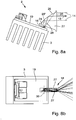
- FIG. 5 Another example of a replacement light source array 2 for use in a light module 1 is shown in various views.
- the primary optics elements 18 are designed as reflectors. These have a square cross-section in the example shown.
- the light exit surfaces 25 of the individual reflectors 18 line up seamlessly and limit the luminous surface with sharp, straight edges.
- Each light source 16 (comprising at least one LED) is preferably associated with a reflector element 18.
- a (perforated) heat shield 22 can be provided between the reflector array 17 and the light source array 15, which protects the back of the reflector array 17 from radiation. The heat shield 22 prevents thermal overload of the reflector material.
- the reflectors 18 extend conically from the light entrance to the light exit 25 out. Perpendicular to an optical axis 23 or to the main radiation direction 29 of the light sources 16 (see. FIG. 8a ), the reflectors 18 preferably have triangular, square or rectangular cross sections. Particularly preferably, the reflectors 18 have the geometry of a truncated pyramid.
- the reflecting surface of the reflectors 18 is preferably made of cylindrical hyperboloids or plane mirrors as a special case of the hyperboloid.
- the reflector array 17 consists of a metallized, high temperature resistant plastic, in particular of a thermoplastic material. High-temperature-resistant thermoplastics which are suitable are, for example, polyether ether ketone, polyether imide or polysulfone.
- the metallization consists for example of aluminum, silver, platinum, gold, nickel, chromium, copper, tin or alloys containing at least one of these metals.
- the metallization is preferably sealed by a transparent layer after application to the reflective surface.
- a multilayer coating can also be applied to the plastic body. Multilayer coating alternately combines several low- and high-index layers.
- a further metal layer may be provided as a radiation barrier.
- This metal layer is deposited, for example as a copper or nickel layer on the plastic body of the reflector array 17 and thus forms a protection against the thermal stress by the radiation of the LEDs 16.
- This metal layer is also capable of heat to the reflector edge in the region of the light exit surface 25 out derive.
- this metal layer is thicker than the metallized mirror layers on the reflective surfaces.
- the reflector edges, ie the light exit surfaces 25 of the individual reflector elements 18 follow the course of a Petzval surface of the secondary optics 4 and are thus on a convexly curved shell (if the projection optics 4 is designed as a reflector) or on a concave curved Shell (when the projection optics 4 is designed as a lens).
- FIG. 6 a further example of a replacement light source array 2 is shown, in which the primary optics elements 18 are formed as optical fibers.
- the light guide array 17 comprises in a straight line juxtaposed light guide 18, each of which widens conically towards the light exit 25.
- the light guides 18 are preferably triangular, square or rectangular cross-sections.
- the light guide elements 18 have a rectangular or square cross-section.
- the light guides 18 have the geometry of a truncated pyramid.
- the light entry surface of the individual light guide elements 18 is preferably flat and runs parallel to a chip surface of the associated light source 16 (comprising at least one LED).
- the light exit surface 25 of the individual light guides 18 is preferably convex.
- the light guide array 17 is made of organic or inorganic glass or silicone rubber (LSR).
- Organic glasses are for example PMMA, COC, COP, PC, PSU or PMMI.
- the light exit surfaces 25 of the conical light guides 18 follow a Petzval products the secondary optics system 4 and are thus on a convexly curved shell (in a projection optics 4 with reflector) or on a concave curved shell (in a projection optics 4 with lens).
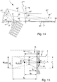
- the replacement light source array 2 includes a primary optics array 17 composed of a plurality of disk-shaped light guides 18.
- the individual light guides 18 each have a light entry surface 24, a light exit surface 25, a reflector surface 26, and two transport surfaces 27, wherein the light entry and exit surfaces 24, 25 in combination with the reflector surface 26 form two focal lines that obey the imaging law:
- the image-side focal line 30a is located on the light exit surface 25 of the light guide 18.
- the lateral transport surfaces 27 of the light guide 18 extend to the light exit surface 25 towards steadily (see. FIG.
- the reflector surface 26 is a control surface.
- the light entry surface 24 of the light guide 18 is preferably flat and runs parallel to the chip surface of the associated LED light source 16. However, it is also conceivable that the light entry surface 24 is slightly inclined relative to the chip surface of the LED 16, so that both surfaces form a conical air gap, which preferably widens toward the trailing edge of the light guide 18. The trailing edge is the edge facing away from the light exit side 25.
- the light exit surface 25 of the light guide 18 is slightly curved, in particular convex.
- the light exit surface 25 of the disc light guides 18 follow the Petzval compounds 20a of the secondary optics system 4 and are thus on a convexly curved shell (at a secondary optics 4 with reflector) or on a concave curved shell (at a secondary optics 4 with lens).
- the array 17 with optical waveguide disks 18 is preferably made of organic or inorganic glass or of silicone rubber LSR.
- Organic glasses are for example PMMA, COC, COP, PC, PSU or PMMI.
- the main emission direction of a light source 16 is representative of all light sources 16 of the light source array 15 by the reference numeral 29.
- the main emission direction 29 coincides with the optical axis of the light source 16.
- Reference numeral 30 denotes a focal line of the light guide 18.
- FIGS. 10 to 14 show various embodiments of a light module 1 according to the invention in section.
- a large part of the optical surface of the secondary optics 4 has a first object-side focal point and a common image-side focal point at infinity.
- the secondary optics 4 thus generates an image of the replacement light source arrangement 2 or its light exit surfaces 25 at infinity.
- the secondary optics system 4 may comprise, for example, a parabolic mirror, in particular a faceted parabolic mirror (cf. FIGS. 1 and 13 ), whose focal point 31 lies on the light exit surface 25 of the primary optic array 17.
- the parabolic reflector 4 is faceted so that all facet surfaces have approximately the same distances from the common focal point 31.
- All of the facet edges facing away from the optical axis (rotation axis) 7 of the light module 1 have greater distances from the common reflector focal point 31 than the facet inner edges lying on the side of the optical axis 7.
- the facet edges are perpendicular to the light-dark boundary of the light distribution 5 (ie vertical light-dark boundary in the striplight ⁇ horizontal facet edges), as in FIG FIG. 1 shown.
- the facet edges can also be circular and concentric around the optical axis 7 (axis of rotation) of the reflector 4, 4 'extend.
- the secondary optics system 4 of the light module 1 can also comprise a converging lens, which is focused on the light exit surfaces 25 of the primary optics elements 18.
- the converging lens may be formed as a toric (astigmatic) converging lens, which has different refractive powers in the meridional and sagittal sections 8, 9.
- the condenser lens can also be designed as an astigmatic condenser lens.
- the secondary optics system 4 may also comprise a color correcting two-lingual system (achromat): a low dispersion color condensing lens and a large color dispersion dispersing lens.
- the secondary optics system 4 comprises a reflector in the form of a hyperboloid 4 'or a plane mirror as a special case of the hyperboloid with a reflector arranged behind it in the form of a paraboloid 4 ", in particular a facetted paraboloid Hyperboloids 4 'lies on the light exit surface 25 of the replacement light source array 2 and forms the object-side focal point of the entire secondary optical system 4.
- the light module 1 is - as stated - shown with a two-part secondary optics system 4, consisting of a plane mirror 4 'and a paraboloid of revolution 4 "The resulting secondary optics system 4 has an optical axis 32 (axis of rotation)
- the paraboloid 4" focuses on the virtual image 2 'the light exit surface 25 of the Spare light source arrays 2, in particular on the centroid of the light exit surface 25 of the replacement light source array. 2
- FIG. 11 Also, there is provided a two-piece secondary optical system 4 having two reflectors 4 ', 4 ".
- the first reflector 4' of the secondary optics system 4 is formed as a concave (collecting) hyperboloid, thereby resulting in an enlarged virtual image of the substitute light source 2 than in the embodiment FIG. 10 , Furthermore, in FIG. 11 the image-side focal point 21 'of the hyperboloid 4' coincides with the focal point of the paraboloid 4 "and marks the position of the virtual intermediate image 2 'of the light exit surface 25 of the replacement light source array 2.
- the secondary optics system 4 is likewise designed in several parts, in particular in two parts.
- the light module 1 comprises a convex hyperboloid 4 '''and a paraboloid 4''
- the resulting secondary optics system 4 has the optical axis 32 (axis of rotation)
- the secondary optics system 4 according to the embodiments of the FIGS. 10 to 12 Thus, two reflectors that are not based on conic sections and no sharp, undistorted intermediate image 2 'of the light exit surface 25 of the spare light source array 2 supply. Rather, the secondary optics system 4 only forms the illuminated area 25 on the roadway.
- the hyperboloid reflector 4, 4 '" may also be faceted.
- the image 21' of the object-side focal point 21 is not at infinity. Therefore, the arrangement of the reflector facets would differ from a spherical surface.
- the facets are preferably arranged so that the respective distances to the object and image-side focal points (hyperbola: virtual image) for all reflector facets have the same conditions as possible, so that the same possible image scales are achieved for all reflector zones.
- the secondary optics system 4 comprises a hyperboloid reflector 4 'and a converging lens 4''''arranged behind the beam path.
- the hyperboloid reflector 4 ' is preferably designed as a horizontally faceted hyperboloid.
- An object-side focal point of the reflector 4 ' is designated by the reference numeral 31 and is located on the light exit surface 25 of the replacement light source assembly 2 or on the centroid thereof.
- the secondary optics system 4 it is possible for the secondary optics system 4 to have an ellipsoid reflector 4 '''''and a diverging lens 4'''''' arranged behind it.
- An object-side focal point 31 of the ellipsoidal reflector 4 ''''' lies on the light exit surface 25 of the replacement light source arrangement 2 or on the Centroid.
- the diverging lens 4 ''''''' focuses on the enlarged image 2 'of the spare light source array 2.
- the ellipsoidal reflector 4 ''''' is preferably formed as a faceted ellipsoid, in particular with horizontal faceting.
- the image 32 of the object-side focal point 31 is not at infinity. Therefore, the arrangement of the reflector facets deviates from a spherical surface.
- the facets are preferably arranged so that the respective distances to the object and image-side focal points (ellipse: real image) for all reflector facets have the same conditions as possible, so that the same possible image scales are achieved for all reflector zones.
- the secondary optics system 4 has a common optical axis 7.
- the light module 1 is intended to provide dynamic cornering light, partial high beam, marker light or the like. to realize as resulting total light distribution 5 by selectively activating or deactivating individual light sources 16 or groups of light sources 16 without mechanically movable parts in the illumination device.
- the light module 1 consisting of the Light source array 15, the primary optics array 17 and the secondary optics system 4, motorized about a vertical and / or horizontal axis relative to the housing of the illumination device in which the light module 1 is arranged, can be pivoted.
- a dynamic cornering light can be pivoted into the curve.
- a sectionfernlicht has a high beam distribution from the targeted specific areas are cut out, in which other road users are.
- a marker light has a dimmed light distribution with a horizontal light-dark boundary, wherein targeted at least a narrow area above the cut-off line is illuminated to illuminate other road users or objects in this area targeted and the driver's attention with The motor vehicle equipped with the light module 1 can be directed to these other road users or objects.
- the light module 1 can rotate about the vertical Axis be formed horizontally pivotable. To adjust a vertical cut-off line, the light module 1 can also be pivoted horizontally about the vertical axis and can be fixed in the adjusted position.
- the light module for adjusting a horizontal cut-off line around a horizontal axis can be pivoted vertically and set in the adjusted position.
- the adjusted position of the cut-off line then forms the zero point for a curve light function and / or headlight range control function to be performed during the operation of the light module 1.
Description
Die vorliegende Erfindung betrifft ein Lichtmodul einer Beleuchtungseinrichtung eines Kraftfahrzeugs. Das Lichtmodul umfasst eine Lichtquellenanordnung mit mehreren separat ansteuerbaren, zu einem Array zusammengefassten Lichtquellen zum Aussenden von Licht, mehrere zu einem Primäroptikarray zusammengefasste Primäroptikelemente in Form von Sammellinsen jeweils mit einer Lichteintrittsfläche und einer Lichtaustrittsfläche und ferner ein Sekundäroptiksystem zum Abbilden des ausgesandten Lichts auf einer Fahrbahn vor dem Kraftfahrzeug als resultierende Gesamtlichtverteilung des Lichtmoduls. Die Primäroptikelemente sind zum Bündeln zumindest eines Teils des von den Lichtquellen ausgesandten Lichts und zum Erzeugen einer Zwischenlichtverteilung auf den Lichtaustrittsflächen ausgebildet. Außerdem betrifft die Erfindung eine Beleuchtungseinrichtung mit einem oder mehreren solcher Lichtmodule.The present invention relates to a light module of a lighting device of a motor vehicle. The light module comprises a light source arrangement having a plurality of separately controllable light sources combined to form an array for emitting light, a plurality of primary optics grouped together to form a primary optic array in the form of converging lenses each having a light entry surface and a light exit surface and also a secondary optics system for imaging the emitted light on a roadway the motor vehicle as the resulting total light distribution of the light module. The primary optics elements are designed to bundle at least part of the light emitted by the light sources and to generate an intermediate light distribution on the light exit surfaces. Moreover, the invention relates to a lighting device with one or more such light modules.
Aus dem Stand der Technik sind verschiedene Ansätze bekannt, ein blendungsfreies Fernlicht mit Hilfe spezieller Lichtmodule, die als Projektionssysteme ausgebildet sind, ohne Verstellmotoren zu realisieren. Hierbei werden aus vielen Halbleiterlichtquellen (z.B. LEDs) mit Hilfe eines Primäroptikarrays Zwischenbilder erzeugt, die über ein Linsensystem auf die Fahrbahn vor das Kraftfahrzeug zur Erzeugung der resultierenden Lichtverteilung des Lichtmoduls projiziert werden. Ein entsprechendes Lichtmodul ist beispielsweise aus der
Da bei derzeitigen Projektionsmodulen nicht nur Hell-Dunkel-Grenzen, sondern auch Dunkel-Hell-Grenzen erzeugt werden, d.h. es gibt keine Festlegung, welche Fahrbahnseite ausgeleuchtet werden soll, können einlinsige Projektionssysteme aufgrund ihrer Farbfehler nur bedingt eingesetzt werden. Zur Lösung dieses Problems ist es beispielsweise aus der
Das Problem einer chromatischen Aberration bei Linsensystemen kann umgangen werden, indem als Sekundär- oder Projektionsoptik ein Reflektor verwendet wird. Reflektorsysteme haben gegenüber Linsensystemen Vorteile, da sie keine Farbfehler aufweisen, einfach und kostengünstig herstellbar sind, insbesondere wenn große optische Flächen gefordert sind, und kein Streulicht durch Fresnelreflexionen verursachen. Nachteilig ist bei Reflektorsystemen dagegen, dass bei größeren numerischen Aperturen Aperturfehler auftreten, d.h. unterschiedliche Reflektorzonen weisen verschiedene Vergrößerungen auf. Darüber hinaus kommt es bei Reflektorsystemen bei achsfernen Strahlen zu einem Versatz (sog. Koma). Eine quadratische Lichtquelle wird also nicht als Quadrat, sondern trapez- oder pilzartig deformiert wiedergegeben, wobei Größe, Lage und Orientierung des Bildes stark von der Lage der Lichtquelle im Objektfeld abhängen können. Ein System, das aus mehreren Halbleiterlichtquellen mehrere gerade, scharf begrenzte Lichtverteilungen mit definierter Lage der einzelnen Hell-Dunkel-Grenzen erzeugen soll, muss jedoch prinzipiell abbildende Eigenschaften aufweisen. Eine entsprechende Gesamtlichtverteilung des Lichtmoduls muss also aus gleich großen und gleich orientierten Lichtquellenbildern aufgebaut bzw. zusammengesetzt werden.The problem of chromatic aberration in lens systems can be circumvented by using a reflector as the secondary or projection optics. Reflector systems have advantages over lens systems because they have no chromatic aberrations, are easy and inexpensive to produce, especially when large optical surfaces are required, and do not cause stray light by Fresnel reflections. A disadvantage of reflector systems, however, that occur at larger numerical apertures aperture errors, ie different reflector zones have different magnifications. In addition, it comes with reflector systems in off-axis rays to an offset (so-called coma). A square light source is therefore not reproduced as a square but trapezoidally or mushroom-like deformed, whereby the size, position and orientation of the image can depend strongly on the position of the light source in the object field. However, a system which is intended to generate several straight, sharply delimited light distributions with a defined position of the individual light-dark boundaries from a plurality of semiconductor light sources must in principle have imaging properties. A corresponding total light distribution of the light module must therefore be constructed or assembled from identically sized and identically oriented light source images.
Darüber hinaus setzen die bekannten Matrix-Fernlichtmodule in der Regel Single-Chip-LEDs, insbesondere SMD (Surface Mounted Device)-LEDs, in Verbindung mit einem Primäroptikarray ein. Das Primäroptikarray erzeugt Zwischenbilder auf den Lichtaustrittsflächen der Primäroptikelemente des Optikarrays), die dann durch die im Strahlengang nachgeordnete Sekundäroptik auf die Fahrbahn projiziert werden. Die Flächen der Zwischenbilder (sog. Pixel) sind bedingt durch die Abstände zwischen den LEDs recht groß, was Projektionslinsen mit sehr großer Brennweite erforderlich macht. Die resultierenden Lichtmodule sind deshalb relativ großbauend, was für den Einsatz in Kraftfahrzeugen nachteilig ist, da dort nur ein relativ beschränkter Einbauraum für die Lichtmodule bzw. die mit diesen ausgestatteten Beleuchtungseinrichtungen zur Verfügung steht.In addition, the known matrix high-beam modules usually use single-chip LEDs, in particular SMD (Surface Mounted Device) LEDs, in conjunction with a primary optics array. The primary optics array generates intermediate images on the light exit surfaces of the primary optics elements of the optical array), which are then projected onto the roadway by the secondary optics downstream in the beam path. The areas of the intermediate images (so-called pixels) are quite large due to the distances between the LEDs, which requires projection lenses with a very large focal length. The resulting light modules are therefore relatively bulky, which is disadvantageous for use in motor vehicles, since there is only a relatively limited installation space for the light modules or equipped with these lighting devices available.
Außer auf die beiden bereits genannten Druckschriften wird noch auf folgende Druckschriften zum Stand der Technik verwiesen:
Diese Aufgabe wird gemäß der vorliegenden Erfindung durch ein Lichtmodul einer Kraftfahrzeugbeleuchtungseinrichtung mit sämtlichen Merkmalen des Patentanspruchs 1 gelöst. Insbesondere wird ausgehend von dem Lichtmodul der eingangs genannten Art vorgeschlagen, dass das Sekundäroptiksystem zum Abbilden der Zwischenlichtverteilungen auf der Fahrbahn vor dem Kraftfahrzeug als resultierende Gesamtlichtverteilung des Lichtmoduls auf mindestens eine der Lichtaustrittsflächen der Sammellinsen fokussiert ist.This object is achieved according to the present invention by a light module of a motor vehicle lighting device having all the features of
Das Lichtmodul umfasst mehrere zu einem Primäroptikarray zusammengefasste Primäroptikelemente jeweils mit einer Lichteintrittsfläche und einer Lichtaustrittsfläche. Die Primäroptikelemente sind zum Bündeln zumindest eines Teils des von den Lichtquellen ausgesandten Lichts und zum Erzeugen von Zwischenlichtverteilungen auf den Lichtaustrittsflächen der Primäroptikelemente ausgebildet. Das Sekundäroptiksystem ist zum Abbilden der Zwischenlichtverteilungen auf der Fahrbahn vor dem Kraftfahrzeug als resultierende Gesamtlichtverteilung des Lichtmoduls auf mindestens eine der Lichtaustrittsflächen fokussiert. Es ist denkbar, dass die Sekundäroptik nicht nur einen Brennpunkt, sondern mehrere Brennpunkte aufweist, wobei mehrere der Brennpunkte auf mehrere der Lichtaustrittsflächen fokussiert sein können. Es ist nicht erforderlich (und in der Praxis auch schwer realisierbar), dass der oder die Brennpunkte der Sekundäroptik auf die Austrittflächen aller Primäroptikelemente fokussiert sind.The light module comprises a plurality of primary optics elements combined to form a primary optic array, each having a light entry surface and a light exit surface. The primary optics elements are designed to bundle at least part of the light emitted by the light sources and to generate intermediate light distributions on the light exit surfaces of the primary optics elements. The secondary optics system is focused on at least one of the light exit surfaces for imaging the intermediate light distributions on the roadway in front of the motor vehicle as the resulting total light distribution of the light module. It is conceivable that the secondary optics not only have one focal point, but a plurality of focal points, wherein a plurality of the focal points may be focused on a plurality of the light exit surfaces. It is not necessary (and in practice also difficult to realize) that the focal point or points of secondary optics are focused on the exit surfaces of all primary optic elements.
Das Lichtmodul umfasst also ein Halbleiterlichtquellenarray sowie ein Primäroptikarray, wobei die auf den Lichtaustrittsflächen des Optikarrays erzeugten Zwischenlichtverteilungen von dem Sekundäroptiksystem auf die Fahrbahn projiziert werden. Es werden also keine Abbilder der Lichtquellen, sondern lediglich beleuchtete Flächen auf die Fahrbahn projiziert. Die Kombination des Lichtquellenarrays mit dem Primäroptikarray wird nachfolgend auch als Ersatzlichtquellenarray bezeichnet. Eine Lichtquelle und das dieser zugeordnete Primäroptikelement wird auch als Ersatzlichtquelle bezeichnet, wobei mehrere Ersatzlichtquellen unmittelbar neben- bzw. übereinander zu einem Array angeordnet werden können. Dabei bilden die in einer oder mehreren Zeilen nebeneinander angeordneten Primäroptikelemente das Primäroptikarray. Da die Primäroptikelemente in der Regel größer als die den Primäroptikelementen jeweils zugeordneten Lichtquellen sind, ergeben sich bei einem Ersatzlichtquellenarray relativ große Abstände zwischen den einzelnen Lichtquellen.The light module thus comprises a semiconductor light source array and a primary optics array, wherein the intermediate light distributions generated on the light exit surfaces of the optical array are projected onto the roadway by the secondary optics system. So there are no images of the Light sources, but only illuminated areas projected onto the road. The combination of the light source array with the primary optics array is also referred to below as a replacement light source array. A light source and the primary optics element associated therewith is also referred to as a substitute light source, wherein a plurality of substitute light sources can be arranged directly next to or above one another to form an array. The primary optic elements arranged side by side in one or more rows form the primary optic array. Since the primary optic elements are generally larger than the light sources respectively associated with the primary optics elements, relatively large distances between the individual light sources result for a replacement light source array.
Im Gegensatz zu herkömmlichen Projektionssystemen erzeugen bei dem erfindungsgemäßen Lichtmodul die Sammellinsen in der objektseitigen Petzvalfläche der Sekundäroptik keine Abbilder der Lichtquellen. Bei dem erfindungsgemäßen Lichtmodul werden die Lichtaustrittsflächen der Sammellinsen lediglich ausgeleuchtet. Auf eine oder mehrere dieser ausgeleuchteten Flächen ist die Sekundäroptik fokussiert. Das Sammellinsenarray weist auf den Lichtaustrittsflächen eine gleichmäßige Leuchtdichte ohne Maxima auf. Dies gilt insbesondere für die Lichtverteilung in den Schnitten senkrecht zu den Helldunkelgrenzen bzw. Pixelgrenzen. Die Sekundäroptik fokussiert also auf die Austrittspupille des Primäroptikarrays.In contrast to conventional projection systems, in the light module according to the invention, the converging lenses in the object-side Petzval surface of the secondary optics do not produce any images of the light sources. In the light module according to the invention, the light exit surfaces of the converging lenses are merely illuminated. The secondary optics are focused on one or more of these illuminated areas. The collecting lens array has a uniform luminance on the light exit surfaces without maxima. This applies in particular to the light distribution in the sections perpendicular to the light-dark boundaries or pixel boundaries. Secondary optics thus focuses on the exit pupil of the primary optic array.
Vorteilhafterweise erfolgt bei dem erfindungsgemäßen Lichtmodul - im Unterschied zu den herkömmlichen Projektionssystemen - die Formung der Lichtverteilung, d.h. den vertikalen und/oder horizontalen Verlauf der Pixel, zur Realisierung der Gesamtlichtverteilung des Lichtmoduls zumindest teilweise durch die Sekundäroptik. Vorzugsweise erfolgt die Formung der Lichtverteilung vollständig oder nahezu vollständig durch die Sekundäroptik. Dies ist insbesondere bei einem Primäroptikarray in Form eines Sammellinsenarrays möglich, da hier keine nennenswerten Beleuchtungsstärkeunterschiede in der Austrittspupille der Primäroptik erzeugt werden können. Dabei kann die Lichtformung also nahezu vollständig durch eine bspw. torische Sekundäroptik erfolgen.Advantageously, in the light module according to the invention - in contrast to the conventional projection systems - the shaping of the light distribution, ie the vertical and / or horizontal course of the pixels, to realize the total light distribution of the light module at least partially by the secondary optics. Preferably, the shaping of the light distribution takes place completely or almost completely by the secondary optics. This is in particular in the case of a primary optic array in the form of a collecting lens array, since no appreciable illuminance differences can be produced in the exit pupil of the primary optics. In this case, the light shaping can thus be almost completely by an example. Toric secondary optics.
Die Lichtquellen sind vorteilhafterweise als Halbleiterlichtquellen, insbesondere als LED-Lichtquellen, LED-Arrays, als Single-Chip-LEDs oder als SMD-LEDs ausgebildet.The light sources are advantageously designed as semiconductor light sources, in particular as LED light sources, LED arrays, as single-chip LEDs or as SMD LEDs.
Die Sekundäroptik kann gemäß verschiedenen bevorzugten Ausführungsformen der Erfindung wie folgt ausgebildet sein:
- 1. als Parabelreflektor, insbesondere als ein facettierter Parabelreflektor,
- 2. als eine Sammellinse, insbesondere als eine aplanatische Sammellinse,
- 3. als ein Achromat mit einer Kombination aus einer Sammellinse mit kleiner Farbdispersion und einer Zerstreuungslinse mit großer Farbdispersion,
- 4. als eine Kombination eines hyperbolischen Reflektors mit einer Sammellinse, wobei ein objektseitiger Brennpunkt der Sammellinse und ein bildseitiger Brennpunkt des Hyperbelreflektors zusammenfallen, oder
- 5. als eine Kombination eines elliptischen Reflektors mit einer Zerstreuungslinse, wobei ein objektseitiger Brennpunkt der Zerstreuungslinse und ein bildseitiger Brennpunkt des Ellipsoidreflektors zusammenfallen.
- 1. as a parabolic reflector, in particular as a faceted parabolic reflector,
- 2. as a condenser lens, in particular as an aplanatic condenser lens,
- 3. as an achromatic with a combination of a condensing lens with small color dispersion and a diverging lens with large color dispersion,
- 4. as a combination of a hyperbolic reflector with a condenser lens, wherein an object-side focal point of the condenser lens and an image-side focal point of the hyperbolic reflector coincide, or
- 5. as a combination of an elliptical reflector with a diverging lens, wherein an object-side focal point of the diverging lens and an image-side focal point of the ellipsoidal reflector coincide.
Das Primäroptikarray kann wie folgt ausgebildet sein:
- 1. Als ein Sammellinsenarray, insbesondere als ein Array aus Plankonvexlinsen. Besonders vorteilhaft ist ein Linsenarray mit torischen Linsenflächen.
- 2. Als ein Reflektorarray, insbesondere mit mehreckiger Querschnittsfläche, vorzugsweise mit quadratischem, rechteckigem oder dreieckigem Reflektorquerschnitt. Die Reflektorflächen werden vorzugsweise als ebene Spiegelflächen oder als zylindrische Hyperboloidflächen ausgebildet.
- 3. Als ein Lichtleiterarray, wobei die einzelnen Lichtleiter vorzugsweise als konische Lichtleiter mit einer von ihrer Lichteintrittsfläche zu ihrer Lichtaustrittsfläche hin zunehmenden Querschnittsfläche. Die Lichtleiter haben vorzugsweise einen mehreckigen, vorzugsweise einen dreieckigen, rechteckigen oder quadratischen Querschnitt. Eine Lichteintrittsfläche eines Lichtleiters wird vorteilhafterweise als ebene Fläche ausgebildet, die orthogonal zur Hauptabstrahlrichtung der ihr zugeordneten Halbleiterlichtquelle, insbesondere parallel zur Flächenerstreckung eines Halbleiterchips, angeordnet ist. Eine Lichtaustrittsfläche eines Lichtleiters weist vorzugsweise eine konvexe Wölbung auf.
- 4. Als ein Lichtleiterarray mit mehreren scheibenförmigen Lichtleitern. Die Lichtleiterscheiben weisen jeweils eine Lichteintrittsfläche, eine Lichtaustrittsfläche, eine Reflektorfläche und zwei Transportflächen auf, an denen in den Lichtleiter eingekoppeltes Licht mittels Totalreflexion zu der Lichtaustrittsfläche transportiert wird. Die Reflektorfläche ist vorzugsweise zwischen den Lichteintritts- und Lichtaustrittsflächen angeordnet. Die Lichteintritts- und Lichtaustrittsflächen bilden vorteilhafterweise in Verbindung mit der Reflektorfläche zwei Brennlinien, die dem Abbildungsgesetz gehorchen. Das bedeutet, dass die optischen Wege zwischen der objektseitigen und der bildseitigen Brennlinie gleiche optische Weglängen aufweisen: Die Summei (si x ni) = konstant.
- 1. As a collection lens array, in particular as an array of plano-convex lenses. Particularly advantageous is a lens array with toric lens surfaces.
- 2. As a reflector array, in particular with a polygonal cross-sectional area, preferably with a square, rectangular or triangular reflector cross-section. The reflector surfaces are preferably formed as flat mirror surfaces or as cylindrical hyperboloidal surfaces.
- 3. As an optical waveguide array, the individual optical waveguides preferably being conical light guides having a cross-sectional area increasing from their light entry surface to their light exit surface. The light guides preferably have a polygonal, preferably a triangular, rectangular or square cross section. A light entry surface of a light guide is advantageously formed as a flat surface which is orthogonal to the main emission of the associated semiconductor light source, in particular parallel to the surface extension of a semiconductor chip arranged. A light exit surface of a light guide preferably has a convex curvature.
- 4. As a light guide array with several disc-shaped light guides. The optical waveguide disks each have a light entry surface, a light exit surface, a reflector surface and two transport surfaces, at which light coupled into the optical waveguide is transported to the light exit surface by total reflection. The reflector surface is preferably arranged between the light entry and light exit surfaces. The light entrance and light exit surfaces advantageously form in combination with the reflector surface two focal lines that obey the imaging law. This means that the optical paths between the Object side and the image-side focal line have the same optical path lengths: The sum i (s i xn i ) = constant.
Wenn zwei- oder mehrteilige Sekundäroptiken zum Einsatz kommen, fällt der bildseitige Brennpunkt, der in Abstrahlrichtung vorangestellten Primäroptik mit dem objektseitigen Brennpunkt der nachfolgenden Sekundäroptik zusammen. Beide Optiken haben gleiche optische Achsen (Rotationsachsen von Linsen und Reflektoren). Eine Sekundäroptik mit mehreren hintereinander geschalteten Reflektoren oder Spiegeln erlaubt es, den Strahlengang zu falten, wodurch sich die Baulänge des Lichtmoduls entscheidend verkürzt.If two- or multi-part secondary optics are used, the image-side focal point, the primary optics in the emission direction coincides with the object-side focal point of the subsequent secondary optics. Both optics have the same optical axes (axes of rotation of lenses and reflectors). A secondary optic with several reflectors or mirrors connected in series allows the optical path to be folded, which considerably shortens the overall length of the light module.
Der Brennpunkt der Sekundäroptik liegt vorzugsweise auf einer Lichtaustrittsfläche des Ersatzlichtquellenarrays und bildet diese auf die Fahrbahn ab. Um eine gute Abbildungsqualität zu erzielen, wird die Sekundäroptik so ausgestaltet, dass alle optischen Wege zwischen dem Brennpunkt und dem (unendlich entfernten) Bildpunkt gleich lang sind. Bei Verwendung von Reflektoren als Primäroptik und/oder Sekundäroptik (Paraboloid-, Hyperboloid- oder Ellipsoidreflektoren) erreicht man dies bspw. mit folgenden Maßnahmen:
- Das Lichtquellen- bzw. Ersatzlichtquellenarray strahlt unter einem spitzen Winkel vorzugsweise entgegen der Fahrtrichtung des Fahrzeugs oder schräg dazu in den Reflektor, d.h. der Strahlengang wird durch den Reflektor in einem spitzen Winkel gefaltet. Ferner ist der Reflektor vorzugsweise derart facettiert, dass alle Facettenflächen etwa gleich große Abstände zu einem gemeinsamen Brennpunkt des Reflektors aufweisen. Alle von der optischen Achse (Rotationsachse) des Lichtmoduls abgewandten Facettenkanten haben größere Abstände zu dem gemeinsamen Reflektorbrennpunkt als die Facetteninnenkanten, die auf der Seite der optischen Achse liegen. Vorzugsweise verlaufen die Facettenkanten senkrecht zu den Hell-Dunkel-Grenzen der resultierenden Gesamtlichtverteilung (z.B. vertikale Hell-Dunkel-Grenze beim Streifenfernlicht → horizontale Facettenkanten). Auch konzentrisch um die optische Achse angeordnete kreisringförmige Reflektorfacetten sind vorteilhaft.
- The light source or replacement light source array radiates at an acute angle, preferably counter to the direction of travel of the vehicle or obliquely in the reflector, ie, the beam path is folded by the reflector at an acute angle. Furthermore, the reflector is preferably faceted such that all facet surfaces have approximately equal distances to a common focal point of the reflector. All facet edges facing away from the optical axis (rotation axis) of the light module have greater distances to the common reflector focal point than the facet inner edges, which lie on the side of the optical axis. Preferably, the facet edges are perpendicular to the light-dark boundaries of the resulting total light distribution (eg vertical cut-off for the stripline → horizontal facet edges). Also concentric about the optical axis arranged annular reflector facets are advantageous.
Es folgt eine Aufstellung mit verschiedenen Kombinationen von Lichtquellen, Primäroptiken und Sekundäroptiken. All diejenigen Kombinationen, die Gegenstand der vorliegenden Erfindung sein sollen, sind durch ein X gekennzeichnet. Diejenigen Kombinationen, die sowohl aus technischer Sicht als auch vom erzielbaren Ergebnis her ebenfalls interessante Lösungen darstellen, sind mit X' gekennzeichnet:
Weitere Merkmale und Vorteile der vorliegenden Erfindung ergeben sich unter Bezugnahme auf die Figuren aus der nachfolgenden Beschreibung. Dabei kann das erfindungsgemäße Lichtmodul die bezüglich der verschiedenen Ausführungsformen angegebenen Merkmale und Vorteile auch jeweils einzeln oder in einer beliebig anderen Kombination als in den Ausführungsbeispielen erläutert aufweisen. Es zeigen:
- Fig. 1
- ein erfindungsgemäßes Lichtmodul gemäß einer ersten bevorzugten Ausführungsform;
- Fig. 2
- Lichtquellen zur Verwendung in einem erfindungsgemäßen Lichtmodul gemäß einer bevorzugten Ausführungsform;
- Fig. 3
- Ersatzlichtquellen zur Verwendung in einem erfindungsgemäßen Lichtmodul gemäß einer bevorzugten Ausführungsform;
- Fig. 4
- verschiedene Ansichten von Ersatzlichtquellen nach
Fig. 3 ; - Fig. 5
- verschiedene Ansichten von alternativen Ersatzlichtquellen zur Verwendung in einem alternativen Lichtmodul;
- Fig. 6
- verschiedene Ansichten von alternativen Ersatzlichtquellen zur Verwendung in einem alternativen Lichtmodul ;
- Fig. 7
- verschiedene Ansichten von alternativen Ersatzlichtquellen zur Verwendung in einem alternativen Lichtmodul;
- Fig. 8
- eine Seitenansicht und eine Draufsicht auf eine Ersatzlichtquelle vom Typ der in
Figur 7 - Fig. 9
- einen Ausschnitt aus
Fig. 8a mit beispielhaft eingezeichneten Strahlverläufen; - Fig. 10
- ein erfindungsgemäßes Lichtmodul gemäß einer bevorzugten Ausführungsform in einer Seitenansicht mit beispielhaft eingezeichneten Strahlverläufen;
- Fig. 11
- ein erfindungsgemäßes Lichtmodul gemäß einer bevorzugten Ausführungsform in einer Seitenansicht mit beispielhaft eingezeichneten Strahlverläufen;
- Fig. 12
- ein erfindungsgemäßes Lichtmodul gemäß einer bevorzugten Ausführungsform in einer Seitenansicht mit beispielhaft eingezeichneten Strahlverläufen;
- Fig. 13
- ein erfindungsgemäßes Lichtmodul gemäß einer bevorzugten Ausführungsform in einer Seitenansicht mit beispielhaft eingezeichneten Strahlverläufen;
- Fig. 14
- ein erfindungsgemäßes Lichtmodul gemäß einer bevorzugten Ausführungsform in einer Seitenansicht mit beispielhaft eingezeichneten Strahlverläufen; und
- Fig. 15
- einen Ausschnitt aus einer Ersatzlichtquellenanordnung zur Verwendung in einem Lichtmodul gemäß der vorliegenden Erfindung.
- Fig. 1
- an inventive light module according to a first preferred embodiment;
- Fig. 2
- Light sources for use in a light module according to the invention according to a preferred embodiment;
- Fig. 3
- Replacement light sources for use in a light module according to the invention according to a preferred embodiment;
- Fig. 4
- different views of replacement light sources
Fig. 3 ; - Fig. 5
- different views of alternative replacement light sources for use in an alternative light module;
- Fig. 6
- different views of alternative replacement light sources for use in an alternative light module;
- Fig. 7
- different views of alternative replacement light sources for use in an alternative light module;
- Fig. 8
- a side view and a plan view of a spare light source of the type in
FIG. 7 shown spare light sources; - Fig. 9
- a section from
Fig. 8a with exemplified beam paths; - Fig. 10
- an inventive light module according to a preferred embodiment in a side view with exemplified drawn beam paths;
- Fig. 11
- an inventive light module according to a preferred embodiment in a side view with exemplified drawn beam paths;
- Fig. 12
- an inventive light module according to a preferred embodiment in a side view with exemplified drawn beam paths;
- Fig. 13
- an inventive light module according to a preferred embodiment in a side view with exemplified drawn beam paths;
- Fig. 14
- an inventive light module according to a preferred embodiment in a side view with exemplified drawn beam paths; and
- Fig. 15
- a section of a replacement light source arrangement for use in a light module according to the present invention.
Die vorliegende Erfindung betrifft ein Lichtmodul, das in den Figuren in seiner Gesamtheit und mit dem Bezugszeichen 1 bezeichnet ist. Das Lichtmodul 1 ist zum Einbau in einer Beleuchtungseinrichtung (nicht dargestellt) eines Kraftfahrzeugs vorgesehen. Die Beleuchtungseinrichtung ist vorzugsweise als ein Kraftfahrzeugscheinwerfer ausgebildet. Sie kann aber auch als eine Kraftfahrzeugleuchte ausgebildet sein. Sie umfasst üblicherweise ein Gehäuse mit einer Lichtaustrittsöffnung, die mittels einer transparenten Abdeckscheibe verschlossen ist. Das Lichtmodul 1 kann starr oder beweglich in dem Gehäuse angeordnet sein. Durch Bewegen des Lichtmoduls 1 relativ zu dem Gehäuse kann eine Leuchtweitenregelung und/oder eine Kurvenlichtfunktion realisiert werden. Es können mehrere erfindungsgemäße Lichtmodule 1 in dem Gehäuse angeordnet sein. Es ist aber auch denkbar, dass das erfindungsgemäße Lichtmodul 1 zusammen mit anderen nicht erfindungsgemäß ausgebildeten Lichtmodulen in dem Gehäuse angeordnet ist.The present invention relates to a light module, which is designated in the figures in its entirety and by the
Das erfindungsgemäße Lichtmodul 1 umfasst eine Lichtquellenanordnung 15 (vgl.
Die Sekundäroptik 4 fokussiert vorzugsweise auf die Lichtaustrittsflächen 25 des Ersatzlichtquellenarrays 2 bzw. der Primäroptikelemente 18. Bei dem Lichtmodul 1 werden die von den Lichtquellen auf den Lichtaustrittsflächen 25 des Primäroptikarrays 17 erzeugten Zwischenlichtverteilungen vorzugsweise derart miteinander kombiniert, dass sich die Einzellichtverteilungen 6' zumindest partiell überlagern bzw. addieren und so die resultierende Gesamtlichtverteilung 5 des Lichtmoduls 1 bilden. Die Gesamtlichtverteilung 5 ist bspw. ein sog. blendungsfreies Fernlicht. Bei dem erfindungsgemäßen Lichtmodul 1 werden also lediglich die Zwischenlichtverteilungen auf den Lichtaustrittsflächen 25 der Primäroptikelemente 18, d.h. die beleuchteten Flächen 25, und nicht Abbilder der Lichtquellen 16 von der Sekundäroptik 4 auf der Fahrbahn abgebildet. Zu diesem Zweck ist die Sekundäroptik 4 nicht auf Abbilder der Lichtquellen 16, sondern auf die Lichtaustrittsflächen 25 der Primäroptikelemente 18 fokussiert.The
Der LED-Chip 16 liegt zwischen der Linse 18 und deren objektseitigem Brennpunkt F. Der LED-Chip 16 wird durch die Linse 18 so vergrößert, dass das (aufrechte) virtuelle Bild 16' des Chips (in Lichtaustrittsrichtung vor dem objektseitigen Linsenbrennpunkt F) etwa gleich groß ist wie die Linse 18, d.h. B'LED ≈ T. Für die angegebenen Größen gelten näherungsweise folgende Zusammenhänge: 
![]()
![]()
![]()
![]()
Die Sammellinsen 18 des Linsenarrays 17 dienen nicht zur Erzeugung reeller Zwischenbilder der Lichtquellen 16, sondern bilden lediglich eine ausgeleuchtete Fläche auf der Lichtaustrittsseite 25 der Sammellinsen 18. Die Lichtquellen 16 sind derart zwischen den Lichteintrittsflächen der Linsen 18 und den objektseitigen Brennpunkten F der Linsen 18 angeordnet, dass die Ränder der Lichtquellen 16 auf geometrischen Verbindungen von den Brennpunkten F zu den Linsenrändern liegen. Die Abstrahlflächen der Lichtquellen 16 sind senkrecht zu den optischen Achsen der Linsen 18 angeordnet. Dadurch ergibt sich eine sehr gleichmäßige Ausleuchtung der Linsen 18 und auf den Lichtaustrittsflächen 25 der Linsen 18 eine besonders homogene Lichtverteilung, die sog. Zwischenlichtverteilung. Diese Zwischenlichtverteilungen werden durch die Sekundäroptikanordnung 4 zur Erzeugung der resultierenden Gesamtlichtverteilung des Lichtmoduls 1 auf der Fahrbahn vor dem Fahrzeug abgebildet. Die optischen Achsen der Einzellinsen 18 des Arrays 17 verlaufen alle in einer Ebene, bevorzugt sind sie parallel zueinander. Die Achse der Sekundäroptik 4 ist auf der Seite, die der Primäroptik 17 zugewandt ist, parallel zu der Achse mindestens einer der Linsen 18.The collecting
Das Sekundäroptiksystem 4 ist in dem dargestellten Beispiel als ein horizontal facettierter Reflektor, insbesondere Parabelreflektor, ausgebildet. D.h. in einem Vertikalschnitt umfasst der Reflektor 4 mehrere übereinander angeordnete Facetten. Das Sekundäroptiksystem 4 fokussiert auf die Lichtaustrittsflächen 25 der Primäroptikelemente 18 bzw. des Ersatzlichtquellenarrays 2. Eine resultierende Gesamtlichtverteilung 5 des Lichtmoduls 1 ist beispielhaft auf einem Messschirm 6 abgebildet, der in einem definierten Abstand zu dem Lichtmodul 1 angeordnet ist. Die Gesamtlichtverteilung 5 umfasst eine Vielzahl von Einzellichtverteilungen 6', die von den einzelnen Elementen 16, 18 des Ersatzlichtquellenarrays 2 im Zusammenwirken mit dem Sekundäroptiksystem 4 erzeugt werden.The
Ferner ist in
Ein Brennpunkt des facettierten Parabelreflektors 4 ist in
Bei dem Ausführungsbeispiel aus
Ferner ist in
In
Die Reflektoren 18 erweitern sich konisch vom Lichteintritt zum Lichtaustritt 25 hin. Senkrecht zu einer optischen Achse 23 bzw. zur Hauptabstrahlrichtung 29 der Lichtquellen 16 (vgl.
Die Reflektorränder, d.h. die Lichtaustrittsflächen 25 der einzelnen Reflektorelemente 18 folgen dem Verlauf einer Petzvalfläche der Sekundäroptik 4 und liegen damit auf einer konvex gekrümmten Schale (wenn die Projektionsoptik 4 als Reflektor ausgebildet ist) oder auf einer konkav gekrümmten Schale (wenn die Projektionsoptik 4 als Linse ausgebildet ist).The reflector edges, ie the light exit surfaces 25 of the
In
Die Lichtaustrittsfläche 25 der einzelnen Lichtleiter 18 ist vorzugsweise konvex gewölbt. Das Lichtleiterarray 17 besteht aus organischem oder anorganischem Glas oder aus Silikonkautschuk (LSR). Organische Gläser sind beispielsweise PMMA, COC, COP, PC, PSU oder PMMI. Die Lichtaustrittsflächen 25 der konischen Lichtleiter 18 folgen einer Petzvalfläche des Sekundäroptiksystems 4 und liegen damit auf einer konvex gekrümmten Schale (bei einer Projektionsoptik 4 mit Reflektor) oder auf einer konkav gekrümmten Schale (bei einer Projektionsoptik 4 mit Linse).The
Bei dem Beispiel aus
In
Wie man anhand der
Die
Das Sekundäroptiksystem 4 des erfindungsgemäßen Lichtmoduls 1 kann auch eine Sammellinse umfassen, die auf die Lichtaustrittsflächen 25 der Primäroptikelemente 18 fokussiert ist. Die Sammellinse kann als eine torische (astigmatische) Sammellinse ausgebildet sein, die in Meridional- und Sagittalschnitt 8, 9 unterschiedliche Brechkräfte aufweist. Die Sammellinse kann ferner auch als eine astigmatische Sammellinse ausgebildet sein. Schließlich kann das Sekundäroptiksystem 4 auch ein farbkorrigierendes zweilinsiges System (Achromat) umfassen: eine Sammellinse mit kleiner Farbdispersion und eine Zerstreuungslinse mit großer Farbdispersion.The
In dem in
In
In dem Ausführungsbeispiel aus
Bei dem Ausführungsbeispiel aus
Das Sekundäroptiksystem 4 besteht gemäß der Ausführungsbeispiele aus den
Der Hyperboloidreflektor 4, 4''' kann auch facettiert ausgebildet sein. Bei dem Hyperboloidreflektor 4, 4''' liegt das Bild 21' des objektseitigen Brennpunkts 21 nicht im Unendlichen. Deshalb würde die Anordnung der Reflektorfacetten von einer Kugelfläche abweichen. Die Facetten sind vorzugsweise so angeordnet, dass die jeweiligen Abstände zu den objekt- und bildseitigen Brennpunkten (Hyperbel: virtuelles Bild) für alle Reflektorfacetten möglichst gleiche Verhältnisse aufweisen, so dass für alle Reflektorzonen möglichst gleiche Abbildungsmaßstäbe erreicht werden.The
Gemäß dem Ausführungsbeispiel eines erfindungsgemäßen Lichtmoduls 1 aus
Schließlich ist es gemäß einer weiteren Ausführungsform gemäß der
Der Ellipsoidreflektor 4''''' ist vorzugsweise als facettiertes Ellipsoid, insbesondere mit horizontaler Facettierung, ausgebildet. Bei dem Ellipsoidreflektor 4''''' liegt das Bild 32 des objektseitigen Brennpunkts 31 nicht im Unendlichen. Deshalb weicht die Anordnung der Reflektorfacetten von einer Kugelfläche ab. Die Facetten sind vorzugsweise so angeordnet, dass die jeweiligen Abstände zu den objekt- und bildseitigen Brennpunkten (Ellipse: reelles Bild) für alle Reflektorfacetten möglichst gleiche Verhältnisse aufweisen, so dass für alle Reflektorzonen möglichst gleiche Abbildungsmaßstäbe erreicht werden. Das Sekundäroptiksystem 4 hat eine gemeinsame optische Achse 7. Es besteht aus mehreren Spiegeln und/oder Linsen, die kein scharfes, unverzerrtes Zwischenbild 2' des Ersatzlichtquellenarrays 2 liefern, die aber in der Summe einen objektseitigen Brennpunkt 31 haben, der in einen bildseitigen Brennpunkt im Unendlichen abgebildet wird. Das optische System 1 gehorcht also dem Abbildungsgesetz, nach dem alle optischen Wege zwischen den beiden Brennpunkten gleich lang sind: Summei (si x ni) = konstant, wobei si jeweils der Weg des Strahlengangs i und ni die Brechungsindices der verschiedenen durchlaufenen Medien sind (n1 = n2 = n4 = 1 für Luft; n3 ≠ 1 entsprechend dem Material der Linse 4''''''). In
Eigentlich ist bei dem erfindungsgemäßen Lichtmodul 1 daran gedacht, dynamisches Kurvenlicht, Teilfernlicht, Markierungslicht o.ä. als resultierende Gesamtlichtverteilung 5 durch gezieltes Aktivieren bzw. Deaktivieren von einzelnen Lichtquellen 16 bzw. von Gruppen von Lichtquellen 16 ohne mechanisch bewegbare Teile in der Beleuchtungseinrichtung zu realisieren.Actually, in the
Es ist aber auch denkbar, dass alternativ oder zusätzlich zu der gezielten Aktivierung bzw. Deaktivierung von Lichtquellen 16 zur Erzeugung von dynamischem Kurvenlicht, Teilfernlicht, Markierungslicht als resultierende Gesamtlichtverteilung 5 oder wahlweise zur Justage der Hell-Dunkel-Grenze das Lichtmodul 1, bestehend aus dem Lichtquellenarray 15, dem Primäroptikarray 17 und dem Sekundäroptiksystem 4, motorisch um eine vertikale und/oder horizontale Achse relativ zum Gehäuse der Beleuchtungseinrichtung, in der das Lichtmodul 1 angeordnet ist, geschwenkt werden kann. Dadurch kann beispielsweise ein dynamisches Kurvenlicht in die Kurve hinein geschwenkt werden. Ein Teilfernlicht weist eine Fernlichtverteilung auf, aus der gezielt bestimmte Bereiche herausgeschnitten sind, in denen sich andere Verkehrsteilnehmer befinden. Um einer Bewegung der anderen Verkehrsteilnehmer relativ zu dem mit dem Lichtmodul 1 ausgestatteten Kraftfahrzeug folgen zu können, ist es denkbar das Lichtmodul 1 um die vertikale Achse horizontal zu verschwenken, so dass der aus der Fernlichtverteilung ausgesparte Bereich stets der aktuellen Position der anderen Verkehrsteilnehmer folgt. Ein Markierungslicht weist eine abgeblendete Lichtverteilung mit einer horizontalen Hell-Dunkel-Grenze auf, wobei gezielt mindestens ein eng begrenzter Bereich oberhalb der Hell-Dunkel-Grenze ausgeleuchtet wird, um andere Verkehrsteilnehmer oder Objekte in diesem Bereich gezielt anzuleuchten und die Aufmerksamkeit des Fahrers des mit dem Lichtmodul 1 ausgestatteten Kraftfahrzeugs auf diese anderen Verkehrsteilnehmer oder Objekte zu richten. Um auch hier einer Bewegung der anderen Verkehrsteilnehmer oder der Objekte relativ zu dem Kraftfahrzeug folgen zu können, damit der ausgeleuchtete eng begrenzte Bereich oberhalb der Hell-Dunkel-Grenze stets auf den anderen Verkehrsteilnehmer oder das Objekt gerichtet ist, kann das Lichtmodul 1 um die vertikale Achse horizontal verschwenkbar ausgebildet sein. Zur Justage einer vertikalen Hell-Dunkel-Grenze kann das Lichtmodul 1 ebenfalls um die vertikale Achse horizontal verschwenkbar und in der justierten Position festlegbar sein.However, it is also conceivable that, alternatively or in addition to the targeted activation or deactivation of
Ebenso kann das Lichtmodul zur Justage einer horizontalen Hell-Dunkel-Grenze um eine horizontale Achse vertikal verschwenkt werden und in der justierten Position festgelegt werden. Die justierte Position der Hell-Dunkel-Grenze bildet dann den Nullpunkt für eine während des Betriebs des Lichtmoduls 1 auszuführende Kurvenlichtfunktion und/oder Leuchtweitenregelungsfunktion.Likewise, the light module for adjusting a horizontal cut-off line around a horizontal axis can be pivoted vertically and set in the adjusted position. The adjusted position of the cut-off line then forms the zero point for a curve light function and / or headlight range control function to be performed during the operation of the
Claims (13)
- Light module (1) for a lighting equipment of a motor vehicle comprising a light source assembly with multiple separately controllable light sources (16) combined to an array (15) for emitting light, multiple primary optics elements (18) combined to a primary optics array (17) in the form of collective lenses each of which has a light ingress surface (24) and a light-emitting surface (25), wherein the primary optics elements (18) are designed to bundle at least part of the light emitted by the light sources (16) and to generate intermediate light distributions on the light-emitting surfaces (25), and further comprising a secondary optics system (4) for projecting the emitted light on a road in front of the motor vehicle as resulting overall light distribution (5) of the light module (1), characterized in that the light sources (16) are located between the light ingress surfaces (24) of the collective lenses (18) and that the secondary optics system (4) for projecting the intermediate light distributions on the road in front of the motor vehicle as the resulting overall light distribution (5) of the light module (1) is focused at least on one of the light-emitting surfaces (23) of the collective lenses (18).
- Light module (1) according to Claim 1, characterized in that the light sources of the light source array are designed in the form of SMD LEDs and/or LED chips (16).
- Light module (1) according to Claim 1 or 2, characterized in that the primary optics elements (18) are designed in the form of plano-convex lenses.
- Light module (1) according to any one of the preceding claims, characterized in that the secondary optics system (4) comprises a parabolic reflector, especially a faceted parabolic reflector.
- Light module (1) according to any one of claims 1 to 3, characterized in that the secondary optics system (4) comprises a collective lens, especially an aplanatic collective lens, which show neither spherical aberration nor coma.
- Light module (1) according to any one of claims 1 to 3, characterized in that the secondary optics system (4) comprises an achromatic system with a combination of a collective lens having minor color dispersion and a dispersing lens having major color dispersion.
- Light module (1) according to any one of claims 1 to 3, characterized in that the secondary optics system (4) comprises a combination of a hyperbolic reflector (4') and a collective lens (4"), wherein an object-side focal point (32) of the collective lens (4") coincides with an image-side focal point of the hyperbolic reflector (4').
- Light module (1) according to any one of claims 1 to 3, characterized in that the secondary optics system (4) comprises a combination of an elliptic reflector (4') and a dispersing lens (4"), wherein an object-side focal point (33) of the dispersing lens (4") coincides with an image-side focal point of the ellipsoid reflector (4').
- Light module (1) according to any one of claims 1 to 3, characterized in that the secondary optics system (4) comprises at least one reflector (4; 4', 4", 4''', 4''''), wherein the light sources (16) are arranged and/or aligned in the light module (1) in relation to the reflector in such a way that they radiate with their primary beam direction at an acute angle into the reflector (4; 4', 4", 4''', 4'''') against driving direction of the motor vehicle and the beam path is folded by the reflector (4; 4', 4", 4''', 4'''') at an acute angle.
- Light module (1) according to Claim 9, characterized in that the reflector (4; 4', 4'''') is faceted, wherein all faceted surfaces have approximately the same distances to a collective focal point (12) of the reflector (4; 4', 4'''').
- Light module (1) according to Claim 10, characterized in that facet edges of the faceted reflector (4; 4', 4'''') extend perpendicular to the light-dark boundaries of the individual light distributions (6') generated by the light of the individual light sources (16) on the road in front of the motor vehicle.
- Lighting equipment of a motor vehicle, characterized in that the lighting equipment comprises at least one light module (1) according to any one of the preceding claims.
- Lighting equipment according to Claim 12, characterized in that the lighting equipment comprises a plurality of light modules (1) according to any one of claims 1 to 11, wherein the overall light distributions (5) of several light modules (1) are at least partially superimposed or added to form an overall light distribution of the lighting equipment.
Applications Claiming Priority (1)
| Application Number | Priority Date | Filing Date | Title |
|---|---|---|---|
| DE102013206488.8A DE102013206488A1 (en) | 2013-04-11 | 2013-04-11 | Light module for a motor vehicle lighting device |
Publications (3)
| Publication Number | Publication Date |
|---|---|
| EP2789900A2 EP2789900A2 (en) | 2014-10-15 |
| EP2789900A3 EP2789900A3 (en) | 2016-08-31 |
| EP2789900B1 true EP2789900B1 (en) | 2017-06-21 |
Family
ID=50289565
Family Applications (1)
| Application Number | Title | Priority Date | Filing Date |
|---|---|---|---|
| EP14160764.8A Active EP2789900B1 (en) | 2013-04-11 | 2014-03-19 | Light module for a motor vehicle lighting device |
Country Status (4)
| Country | Link |
|---|---|
| US (1) | US9599304B2 (en) |
| EP (1) | EP2789900B1 (en) |
| CN (1) | CN104100902B (en) |
| DE (1) | DE102013206488A1 (en) |
Families Citing this family (32)
| Publication number | Priority date | Publication date | Assignee | Title |
|---|---|---|---|---|
| ITRM20120265A1 (en) * | 2012-06-07 | 2013-12-08 | Consiglio Nazionale Ricerche | LIGHTING DEVICE INCLUDING AN OPTOELECTRONIC SOURCES BACK |
| DE102013207845A1 (en) * | 2013-04-29 | 2014-10-30 | Automotive Lighting Reutlingen Gmbh | Light module for a motor vehicle headlight |
| DE102014203335A1 (en) * | 2014-02-25 | 2015-08-27 | Automotive Lighting Reutlingen Gmbh | Light module of a motor vehicle headlight and headlights with such a light module |
| JP6581588B2 (en) * | 2014-08-11 | 2019-09-25 | 株式会社小糸製作所 | Vehicle headlamp |
| DE102015202545B4 (en) | 2015-02-12 | 2023-03-23 | Automotive Lighting Reutlingen Gmbh | Motor vehicle lamp with a light-refracting element between the lamp and the paraboloidal reflector |
| DE102015202544B4 (en) * | 2015-02-12 | 2021-02-04 | Automotive Lighting Reutlingen Gmbh | Motor vehicle lamp with a light-refracting element which has the shape of a trimmed hemisphere and whose trimmed boundary surfaces are totally reflective |
| AT516974B1 (en) * | 2015-03-25 | 2017-08-15 | Zkw Group Gmbh | Lighting device for a motor vehicle headlight |
| AT516836B1 (en) * | 2015-04-10 | 2016-09-15 | Zizala Lichtsysteme Gmbh | Lighting device with beam diaphragm and motor vehicle headlights |
| KR101755830B1 (en) | 2015-08-27 | 2017-07-10 | 현대자동차주식회사 | Lamp apparatus for a vehicle |
| DE102015115555B4 (en) | 2015-09-15 | 2022-07-07 | SMR Patents S.à.r.l. | Lighting device, rear view device, footwell device and vehicle |
| FR3041738B1 (en) * | 2015-09-28 | 2020-01-17 | Valeo Vision | PRIMARY OPTICAL ELEMENT FOR LIGHT MODULE OF MOTOR VEHICLE |
| DE102015220338A1 (en) | 2015-10-19 | 2017-04-20 | Automotive Lighting Reutlingen Gmbh | Light module for a lighting device of a motor vehicle |
| AT517885B1 (en) * | 2015-10-23 | 2018-08-15 | Zkw Group Gmbh | Microprojection light module for a motor vehicle headlight for generating aberration-free light distributions |
| FR3048059B1 (en) * | 2016-02-22 | 2022-08-05 | Valeo Vision | LIGHT BEAM PROJECTION DEVICE PROVIDED WITH A MATRIX OF LIGHT SOURCES, LIGHTING MODULE AND HEADLIGHT PROVIDED WITH SUCH A DEVICE |
| FR3048060B1 (en) | 2016-02-22 | 2019-04-05 | Valeo Vision | LIGHT BEAM PROJECTION DEVICE WITH LIGHT SOURCE SUBMATHES, LIGHTING MODULE AND PROJECTOR PROVIDED WITH SUCH A DEVICE |
| KR101795229B1 (en) * | 2016-03-31 | 2017-11-08 | 현대자동차주식회사 | Lamp apparatus for a vehicle |
| US10234094B2 (en) * | 2016-09-13 | 2019-03-19 | Valeo North America, Inc. | Lighting device for producing a supplemental beam |
| FR3055980B1 (en) * | 2016-09-15 | 2019-06-28 | Valeo Vision | OPTICAL SYSTEM FOR PIXELIZED LIGHT BEAM |
| WO2018050337A1 (en) * | 2016-09-15 | 2018-03-22 | Valeo Vision | Lighting module having a monolithic light-emitting source |
| AT519125B1 (en) * | 2017-01-20 | 2018-04-15 | Zkw Group Gmbh | Lighting device for a motor vehicle headlight and motor vehicle headlights |
| JP6865396B2 (en) * | 2017-02-27 | 2021-04-28 | パナソニックIpマネジメント株式会社 | Lighting equipment, lighting systems, and moving objects |
| CN107178751B (en) * | 2017-07-06 | 2023-06-02 | 华域视觉科技(上海)有限公司 | Car light distribution pattern with three-dimensional luminous effect and design generation method thereof |
| DE102017117560A1 (en) * | 2017-08-02 | 2019-02-07 | Automotive Lighting Reutlingen Gmbh | Light module and method for operating the light module |
| EP3495718A1 (en) * | 2017-12-05 | 2019-06-12 | ZKW Group GmbH | Projection device for a motor vehicle headlight |
| CN108397743A (en) * | 2018-04-13 | 2018-08-14 | 华域视觉科技(上海)有限公司 | Optics module and car light |
| CN214332559U (en) * | 2018-05-08 | 2021-10-01 | 亮锐控股有限公司 | Headlight for a motor vehicle |
| DE102018112386A1 (en) | 2018-05-23 | 2019-11-28 | Automotive Lighting Reutlingen Gmbh | Light module with a glass attachment optics and a holder |
| FR3084723B1 (en) * | 2018-07-31 | 2020-08-28 | Valeo Vision | LIGHT MODULE CONTAINING A MATRIX OF LIGHT SOURCES AND A BIFOCAL OPTICAL SYSTEM |
| DE102018127610A1 (en) * | 2018-11-06 | 2020-05-07 | HELLA GmbH & Co. KGaA | Process for producing an optical component, optical component and imaging unit |
| CN209688726U (en) * | 2019-05-20 | 2019-11-26 | 华域视觉科技(上海)有限公司 | A kind of matrix form car light Optical devices, car light and vehicle |
| US11047543B1 (en) * | 2020-05-26 | 2021-06-29 | Valeo Vision Sas | Narrow aperture light system |
| DE102020124423A1 (en) * | 2020-09-18 | 2022-03-24 | HELLA GmbH & Co. KGaA | Lighting device for a motor vehicle |
Family Cites Families (25)
| Publication number | Priority date | Publication date | Assignee | Title |
|---|---|---|---|---|
| US6909554B2 (en) * | 2000-12-27 | 2005-06-21 | Finisar Corporation | Wafer integration of micro-optics |
| US6758582B1 (en) | 2003-03-19 | 2004-07-06 | Elumina Technology Incorporation | LED lighting device |
| TWI233475B (en) | 2004-01-20 | 2005-06-01 | Jau-Tang Lin | Lighting device with increased brightness |
| DE102004008296A1 (en) * | 2004-02-20 | 2005-09-08 | Daimlerchrysler Ag | Headlamp lens for a motor vehicle has a body for light to pass through with Fresnel lenses and channels opposite a source of light |
| US20080062706A1 (en) * | 2006-08-30 | 2008-03-13 | David Charles Feldmeier | Systems, devices, components and methods for controllably configuring the brightness and color of light emitted by an automotive LED illumination system |
| DE102006044640A1 (en) * | 2006-09-19 | 2008-03-27 | Schefenacker Vision Systems Germany Gmbh | Lighting unit for high and low beam generation |
| AT504668B1 (en) * | 2007-01-11 | 2008-07-15 | Zizala Lichtsysteme Gmbh | TOTAL REFLECTION SYSTEM FOR A HEADLIGHT OR A LIGHT UNIT OF A MOTOR VEHICLE |
| FR2921999B1 (en) | 2007-10-04 | 2011-05-06 | Valeo Vision | LIGHTING OR SIGNALING DEVICE FOR MOTOR VEHICLE. |
| DE102007052742A1 (en) | 2007-11-06 | 2009-05-07 | Hella Kgaa Hueck & Co. | Headlights for vehicles |
| DE102008005488B4 (en) | 2008-01-22 | 2016-10-06 | Hella Kgaa Hueck & Co. | Headlights for vehicles |
| DE102008013603B4 (en) | 2008-03-11 | 2017-06-22 | Automotive Lighting Reutlingen Gmbh | Light module for a lighting device |
| JP4582190B2 (en) * | 2008-05-14 | 2010-11-17 | 市光工業株式会社 | Vehicle lighting |
| JP5091808B2 (en) * | 2008-09-02 | 2012-12-05 | 株式会社小糸製作所 | Vehicle lighting |
| US20100260945A1 (en) * | 2009-02-13 | 2010-10-14 | Luminus Devices, Inc. | System and methods for optical curing using a reflector |
| DE102009053581B3 (en) * | 2009-10-05 | 2011-03-03 | Automotive Lighting Reutlingen Gmbh | Light module for a lighting device of a motor vehicle |
| DE102010029176A1 (en) | 2009-10-05 | 2012-12-27 | Automotive Lighting Reutlingen Gmbh | Motor vehicle headlight with a semiconductor light sources, a primary optics and a secondary optics having light module |
| DE102010023360A1 (en) | 2009-10-05 | 2011-04-07 | Automotive Lighting Reutlingen Gmbh | For producing different light distributions vehicle headlights equipped with semiconductor light sources |
| JP4469411B1 (en) * | 2009-10-07 | 2010-05-26 | フェニックス電機株式会社 | Light emitting device |
| JP5457219B2 (en) * | 2010-02-16 | 2014-04-02 | 株式会社小糸製作所 | Optical unit |
| CN102812289B (en) * | 2010-03-31 | 2016-09-21 | 皇家飞利浦电子股份有限公司 | Illuminator and the light source cell for this system |
| JP5562120B2 (en) | 2010-05-21 | 2014-07-30 | スタンレー電気株式会社 | Vehicle lamp unit |
| AT511760B1 (en) * | 2011-08-08 | 2013-12-15 | Zizala Lichtsysteme Gmbh | LED LIGHT SOURCE MODULE FOR A LED MOTOR VEHICLE HEADLIGHT AND LED MOTOR VEHICLE HEADLAMP AND HEADLAMP SYSTEM |
| JP5823211B2 (en) * | 2011-09-01 | 2015-11-25 | 株式会社小糸製作所 | Vehicle headlamp device |
| CN103765086B (en) * | 2011-09-01 | 2016-08-17 | 株式会社小糸制作所 | Vehicle headlamp apparatus |
| DE102012202290B4 (en) * | 2012-02-15 | 2014-03-27 | Automotive Lighting Reutlingen Gmbh | Light module for a glare-free motor vehicle high beam |
-
2013
- 2013-04-11 DE DE102013206488.8A patent/DE102013206488A1/en not_active Withdrawn
-
2014
- 2014-03-19 EP EP14160764.8A patent/EP2789900B1/en active Active
- 2014-03-31 US US14/230,300 patent/US9599304B2/en active Active
- 2014-04-01 CN CN201410128971.4A patent/CN104100902B/en active Active
Also Published As
| Publication number | Publication date |
|---|---|
| DE102013206488A1 (en) | 2014-10-30 |
| EP2789900A2 (en) | 2014-10-15 |
| EP2789900A3 (en) | 2016-08-31 |
| US20140307459A1 (en) | 2014-10-16 |
| CN104100902B (en) | 2017-11-28 |
| CN104100902A (en) | 2014-10-15 |
| US9599304B2 (en) | 2017-03-21 |
Similar Documents
| Publication | Publication Date | Title |
|---|---|---|
| EP2789900B1 (en) | Light module for a motor vehicle lighting device | |
| EP2910847B1 (en) | Light module of a motor vehicle headlight and headlight with such a light module | |
| EP2799762B1 (en) | Light module for a motor vehicle headlamp | |
| EP2587125B1 (en) | Headlamp projection module for a motor vehicle | |
| DE102015115555B4 (en) | Lighting device, rear view device, footwell device and vehicle | |
| EP1818599B1 (en) | Dipped headlight which creates a strongly contrasted cut-off | |
| DE69723542T2 (en) | IMAGE SENSOR | |
| EP2505910B1 (en) | Motor vehicle headlamp with a semiconductor light source | |
| EP2789901B1 (en) | Light module of a motor vehicle lighting device | |
| EP1818600B1 (en) | Dipped headlight with hot spot generation | |
| DE102014210500A1 (en) | Optics for a vehicle lighting device | |
| EP3301350B1 (en) | Light module for a motor vehicle headlamp | |
| DE102012202290A1 (en) | Light module for headlight of motor car, has reflector constructed and arranged to image light-emitting surface, where light emitting surface is imaged with intended use in horizontal running longitudinal edge and vertical running edge | |
| EP2784376A2 (en) | Motor vehicle light for dynamic light functions | |
| DE112017002525T5 (en) | BLOCK FIELD DISPLAY DEVICE AND IMAGE PROJECTION UNIT | |
| DE102008036845B4 (en) | lighting device | |
| EP3765781B1 (en) | Light module for motor vehicle headlight | |
| WO2018185218A2 (en) | Device for displaying an image | |
| EP3699487B1 (en) | Motor vehicle headlight module with variable focal length | |
| EP3149530B1 (en) | Optical body with a lens and light module with the optical body | |
| WO2018149796A2 (en) | Lighting unit and method for controlling emission characteristics thereof, and light mixing guide and lighting unit with a light mixing guide | |
| DE102018207516B3 (en) | Head-up display with one of several distributed light sources illuminated display | |
| EP3385609B1 (en) | Light module for a motor vehicle headlamp | |
| EP3159598B1 (en) | Light module for a lighting device of a motor vehicle | |
| DE102019102134A1 (en) | Motor vehicle headlight light module |
Legal Events
| Date | Code | Title | Description |
|---|---|---|---|
| PUAI | Public reference made under article 153(3) epc to a published international application that has entered the european phase |
Free format text: ORIGINAL CODE: 0009012 |
|
| 17P | Request for examination filed |
Effective date: 20140319 |
|
| AK | Designated contracting states |
Kind code of ref document: A2 Designated state(s): AL AT BE BG CH CY CZ DE DK EE ES FI FR GB GR HR HU IE IS IT LI LT LU LV MC MK MT NL NO PL PT RO RS SE SI SK SM TR |
|
| AX | Request for extension of the european patent |
Extension state: BA ME |
|
| PUAL | Search report despatched |
Free format text: ORIGINAL CODE: 0009013 |
|
| AK | Designated contracting states |
Kind code of ref document: A3 Designated state(s): AL AT BE BG CH CY CZ DE DK EE ES FI FR GB GR HR HU IE IS IT LI LT LU LV MC MK MT NL NO PL PT RO RS SE SI SK SM TR |
|
| AX | Request for extension of the european patent |
Extension state: BA ME |
|
| RIC1 | Information provided on ipc code assigned before grant |
Ipc: F21S 8/10 20060101AFI20160728BHEP |
|
| R17P | Request for examination filed (corrected) |
Effective date: 20160815 |
|
| RBV | Designated contracting states (corrected) |
Designated state(s): AL AT BE BG CH CY CZ DE DK EE ES FI FR GB GR HR HU IE IS IT LI LT LU LV MC MK MT NL NO PL PT RO RS SE SI SK SM TR |
|
| GRAP | Despatch of communication of intention to grant a patent |
Free format text: ORIGINAL CODE: EPIDOSNIGR1 |
|
| INTG | Intention to grant announced |
Effective date: 20170117 |
|
| GRAS | Grant fee paid |
Free format text: ORIGINAL CODE: EPIDOSNIGR3 |
|
| GRAA | (expected) grant |
Free format text: ORIGINAL CODE: 0009210 |
|
| AK | Designated contracting states |
Kind code of ref document: B1 Designated state(s): AL AT BE BG CH CY CZ DE DK EE ES FI FR GB GR HR HU IE IS IT LI LT LU LV MC MK MT NL NO PL PT RO RS SE SI SK SM TR |
|
| REG | Reference to a national code |
Ref country code: GB Ref legal event code: FG4D Free format text: NOT ENGLISH |
|
| REG | Reference to a national code |
Ref country code: CH Ref legal event code: EP |
|
| REG | Reference to a national code |
Ref country code: IE Ref legal event code: FG4D Free format text: LANGUAGE OF EP DOCUMENT: GERMAN |
|
| REG | Reference to a national code |
Ref country code: AT Ref legal event code: REF Ref document number: 903289 Country of ref document: AT Kind code of ref document: T Effective date: 20170715 |
|
| REG | Reference to a national code |
Ref country code: DE Ref legal event code: R096 Ref document number: 502014004292 Country of ref document: DE |
|
| REG | Reference to a national code |
Ref country code: NL Ref legal event code: MP Effective date: 20170621 |
|
| PG25 | Lapsed in a contracting state [announced via postgrant information from national office to epo] |
Ref country code: NO Free format text: LAPSE BECAUSE OF FAILURE TO SUBMIT A TRANSLATION OF THE DESCRIPTION OR TO PAY THE FEE WITHIN THE PRESCRIBED TIME-LIMIT Effective date: 20170921 Ref country code: LT Free format text: LAPSE BECAUSE OF FAILURE TO SUBMIT A TRANSLATION OF THE DESCRIPTION OR TO PAY THE FEE WITHIN THE PRESCRIBED TIME-LIMIT Effective date: 20170621 Ref country code: HR Free format text: LAPSE BECAUSE OF FAILURE TO SUBMIT A TRANSLATION OF THE DESCRIPTION OR TO PAY THE FEE WITHIN THE PRESCRIBED TIME-LIMIT Effective date: 20170621 Ref country code: GR Free format text: LAPSE BECAUSE OF FAILURE TO SUBMIT A TRANSLATION OF THE DESCRIPTION OR TO PAY THE FEE WITHIN THE PRESCRIBED TIME-LIMIT Effective date: 20170922 Ref country code: FI Free format text: LAPSE BECAUSE OF FAILURE TO SUBMIT A TRANSLATION OF THE DESCRIPTION OR TO PAY THE FEE WITHIN THE PRESCRIBED TIME-LIMIT Effective date: 20170621 |
|
| REG | Reference to a national code |
Ref country code: LT Ref legal event code: MG4D |
|
| REG | Reference to a national code |
Ref country code: DE Ref legal event code: R079 Ref document number: 502014004292 Country of ref document: DE Free format text: PREVIOUS MAIN CLASS: F21S0008100000 Ipc: F21S0043000000 |
|
| PG25 | Lapsed in a contracting state [announced via postgrant information from national office to epo] |
Ref country code: SE Free format text: LAPSE BECAUSE OF FAILURE TO SUBMIT A TRANSLATION OF THE DESCRIPTION OR TO PAY THE FEE WITHIN THE PRESCRIBED TIME-LIMIT Effective date: 20170621 Ref country code: RS Free format text: LAPSE BECAUSE OF FAILURE TO SUBMIT A TRANSLATION OF THE DESCRIPTION OR TO PAY THE FEE WITHIN THE PRESCRIBED TIME-LIMIT Effective date: 20170621 Ref country code: LV Free format text: LAPSE BECAUSE OF FAILURE TO SUBMIT A TRANSLATION OF THE DESCRIPTION OR TO PAY THE FEE WITHIN THE PRESCRIBED TIME-LIMIT Effective date: 20170621 Ref country code: BG Free format text: LAPSE BECAUSE OF FAILURE TO SUBMIT A TRANSLATION OF THE DESCRIPTION OR TO PAY THE FEE WITHIN THE PRESCRIBED TIME-LIMIT Effective date: 20170921 Ref country code: NL Free format text: LAPSE BECAUSE OF FAILURE TO SUBMIT A TRANSLATION OF THE DESCRIPTION OR TO PAY THE FEE WITHIN THE PRESCRIBED TIME-LIMIT Effective date: 20170621 |
|
| PG25 | Lapsed in a contracting state [announced via postgrant information from national office to epo] |
Ref country code: SK Free format text: LAPSE BECAUSE OF FAILURE TO SUBMIT A TRANSLATION OF THE DESCRIPTION OR TO PAY THE FEE WITHIN THE PRESCRIBED TIME-LIMIT Effective date: 20170621 Ref country code: RO Free format text: LAPSE BECAUSE OF FAILURE TO SUBMIT A TRANSLATION OF THE DESCRIPTION OR TO PAY THE FEE WITHIN THE PRESCRIBED TIME-LIMIT Effective date: 20170621 Ref country code: CZ Free format text: LAPSE BECAUSE OF FAILURE TO SUBMIT A TRANSLATION OF THE DESCRIPTION OR TO PAY THE FEE WITHIN THE PRESCRIBED TIME-LIMIT Effective date: 20170621 Ref country code: EE Free format text: LAPSE BECAUSE OF FAILURE TO SUBMIT A TRANSLATION OF THE DESCRIPTION OR TO PAY THE FEE WITHIN THE PRESCRIBED TIME-LIMIT Effective date: 20170621 |
|
| REG | Reference to a national code |
Ref country code: FR Ref legal event code: PLFP Year of fee payment: 5 |
|
| PG25 | Lapsed in a contracting state [announced via postgrant information from national office to epo] |
Ref country code: SM Free format text: LAPSE BECAUSE OF FAILURE TO SUBMIT A TRANSLATION OF THE DESCRIPTION OR TO PAY THE FEE WITHIN THE PRESCRIBED TIME-LIMIT Effective date: 20170621 Ref country code: PL Free format text: LAPSE BECAUSE OF FAILURE TO SUBMIT A TRANSLATION OF THE DESCRIPTION OR TO PAY THE FEE WITHIN THE PRESCRIBED TIME-LIMIT Effective date: 20170621 Ref country code: IS Free format text: LAPSE BECAUSE OF FAILURE TO SUBMIT A TRANSLATION OF THE DESCRIPTION OR TO PAY THE FEE WITHIN THE PRESCRIBED TIME-LIMIT Effective date: 20171021 Ref country code: IT Free format text: LAPSE BECAUSE OF FAILURE TO SUBMIT A TRANSLATION OF THE DESCRIPTION OR TO PAY THE FEE WITHIN THE PRESCRIBED TIME-LIMIT Effective date: 20170621 Ref country code: ES Free format text: LAPSE BECAUSE OF FAILURE TO SUBMIT A TRANSLATION OF THE DESCRIPTION OR TO PAY THE FEE WITHIN THE PRESCRIBED TIME-LIMIT Effective date: 20170621 |
|
| REG | Reference to a national code |
Ref country code: DE Ref legal event code: R097 Ref document number: 502014004292 Country of ref document: DE |
|
| PLBE | No opposition filed within time limit |
Free format text: ORIGINAL CODE: 0009261 |
|
| STAA | Information on the status of an ep patent application or granted ep patent |
Free format text: STATUS: NO OPPOSITION FILED WITHIN TIME LIMIT |
|
| PG25 | Lapsed in a contracting state [announced via postgrant information from national office to epo] |
Ref country code: DK Free format text: LAPSE BECAUSE OF FAILURE TO SUBMIT A TRANSLATION OF THE DESCRIPTION OR TO PAY THE FEE WITHIN THE PRESCRIBED TIME-LIMIT Effective date: 20170621 |
|
| 26N | No opposition filed |
Effective date: 20180322 |
|
| PG25 | Lapsed in a contracting state [announced via postgrant information from national office to epo] |
Ref country code: SI Free format text: LAPSE BECAUSE OF FAILURE TO SUBMIT A TRANSLATION OF THE DESCRIPTION OR TO PAY THE FEE WITHIN THE PRESCRIBED TIME-LIMIT Effective date: 20170621 |
|
| PG25 | Lapsed in a contracting state [announced via postgrant information from national office to epo] |
Ref country code: MT Free format text: LAPSE BECAUSE OF FAILURE TO SUBMIT A TRANSLATION OF THE DESCRIPTION OR TO PAY THE FEE WITHIN THE PRESCRIBED TIME-LIMIT Effective date: 20170621 |
|
| REG | Reference to a national code |
Ref country code: CH Ref legal event code: PL |
|
| GBPC | Gb: european patent ceased through non-payment of renewal fee |
Effective date: 20180319 |
|
| PG25 | Lapsed in a contracting state [announced via postgrant information from national office to epo] |
Ref country code: MC Free format text: LAPSE BECAUSE OF FAILURE TO SUBMIT A TRANSLATION OF THE DESCRIPTION OR TO PAY THE FEE WITHIN THE PRESCRIBED TIME-LIMIT Effective date: 20170621 |
|
| REG | Reference to a national code |
Ref country code: BE Ref legal event code: MM Effective date: 20180331 |
|
| REG | Reference to a national code |
Ref country code: IE Ref legal event code: MM4A |
|
| PG25 | Lapsed in a contracting state [announced via postgrant information from national office to epo] |
Ref country code: LU Free format text: LAPSE BECAUSE OF NON-PAYMENT OF DUE FEES Effective date: 20180319 |
|
| PG25 | Lapsed in a contracting state [announced via postgrant information from national office to epo] |
Ref country code: IE Free format text: LAPSE BECAUSE OF NON-PAYMENT OF DUE FEES Effective date: 20180319 |
|
| PG25 | Lapsed in a contracting state [announced via postgrant information from national office to epo] |
Ref country code: GB Free format text: LAPSE BECAUSE OF NON-PAYMENT OF DUE FEES Effective date: 20180319 Ref country code: LI Free format text: LAPSE BECAUSE OF NON-PAYMENT OF DUE FEES Effective date: 20180331 Ref country code: CH Free format text: LAPSE BECAUSE OF NON-PAYMENT OF DUE FEES Effective date: 20180331 Ref country code: BE Free format text: LAPSE BECAUSE OF NON-PAYMENT OF DUE FEES Effective date: 20180331 |
|
| PG25 | Lapsed in a contracting state [announced via postgrant information from national office to epo] |
Ref country code: TR Free format text: LAPSE BECAUSE OF FAILURE TO SUBMIT A TRANSLATION OF THE DESCRIPTION OR TO PAY THE FEE WITHIN THE PRESCRIBED TIME-LIMIT Effective date: 20170621 |
|
| PG25 | Lapsed in a contracting state [announced via postgrant information from national office to epo] |
Ref country code: PT Free format text: LAPSE BECAUSE OF FAILURE TO SUBMIT A TRANSLATION OF THE DESCRIPTION OR TO PAY THE FEE WITHIN THE PRESCRIBED TIME-LIMIT Effective date: 20170621 Ref country code: HU Free format text: LAPSE BECAUSE OF FAILURE TO SUBMIT A TRANSLATION OF THE DESCRIPTION OR TO PAY THE FEE WITHIN THE PRESCRIBED TIME-LIMIT; INVALID AB INITIO Effective date: 20140319 |
|
| PG25 | Lapsed in a contracting state [announced via postgrant information from national office to epo] |
Ref country code: CY Free format text: LAPSE BECAUSE OF FAILURE TO SUBMIT A TRANSLATION OF THE DESCRIPTION OR TO PAY THE FEE WITHIN THE PRESCRIBED TIME-LIMIT Effective date: 20170621 Ref country code: MK Free format text: LAPSE BECAUSE OF NON-PAYMENT OF DUE FEES Effective date: 20170621 |
|
| PG25 | Lapsed in a contracting state [announced via postgrant information from national office to epo] |
Ref country code: AL Free format text: LAPSE BECAUSE OF FAILURE TO SUBMIT A TRANSLATION OF THE DESCRIPTION OR TO PAY THE FEE WITHIN THE PRESCRIBED TIME-LIMIT Effective date: 20170621 |
|
| PGFP | Annual fee paid to national office [announced via postgrant information from national office to epo] |
Ref country code: AT Payment date: 20220218 Year of fee payment: 9 |
|
| PGFP | Annual fee paid to national office [announced via postgrant information from national office to epo] |
Ref country code: FR Payment date: 20230222 Year of fee payment: 10 |
|
| PGFP | Annual fee paid to national office [announced via postgrant information from national office to epo] |
Ref country code: DE Payment date: 20230221 Year of fee payment: 10 |
|
| P01 | Opt-out of the competence of the unified patent court (upc) registered |
Effective date: 20230508 |
|
| REG | Reference to a national code |
Ref country code: AT Ref legal event code: MM01 Ref document number: 903289 Country of ref document: AT Kind code of ref document: T Effective date: 20230319 |
|
| PG25 | Lapsed in a contracting state [announced via postgrant information from national office to epo] |
Ref country code: AT Free format text: LAPSE BECAUSE OF NON-PAYMENT OF DUE FEES Effective date: 20230319 |