EP3301350B1 - Light module for a motor vehicle headlamp - Google Patents
Light module for a motor vehicle headlamp Download PDFInfo
- Publication number
- EP3301350B1 EP3301350B1 EP17190034.3A EP17190034A EP3301350B1 EP 3301350 B1 EP3301350 B1 EP 3301350B1 EP 17190034 A EP17190034 A EP 17190034A EP 3301350 B1 EP3301350 B1 EP 3301350B1
- Authority
- EP
- European Patent Office
- Prior art keywords
- light
- optics
- module
- light module
- per
- Prior art date
- Legal status (The legal status is an assumption and is not a legal conclusion. Google has not performed a legal analysis and makes no representation as to the accuracy of the status listed.)
- Active
Links
- 238000009826 distribution Methods 0.000 claims description 96
- 230000003287 optical effect Effects 0.000 claims description 46
- 239000004065 semiconductor Substances 0.000 claims description 33
- 239000012780 transparent material Substances 0.000 claims description 2
- 238000007596 consolidation process Methods 0.000 claims 1
- 230000001939 inductive effect Effects 0.000 claims 1
- 230000003044 adaptive effect Effects 0.000 description 5
- 238000003384 imaging method Methods 0.000 description 5
- 238000004519 manufacturing process Methods 0.000 description 4
- 229920003023 plastic Polymers 0.000 description 4
- IYLGZMTXKJYONK-ACLXAEORSA-N (12s,15r)-15-hydroxy-11,16-dioxo-15,20-dihydrosenecionan-12-yl acetate Chemical compound O1C(=O)[C@](CC)(O)C[C@@H](C)[C@](C)(OC(C)=O)C(=O)OCC2=CCN3[C@H]2[C@H]1CC3 IYLGZMTXKJYONK-ACLXAEORSA-N 0.000 description 3
- 230000004907 flux Effects 0.000 description 3
- 238000001746 injection moulding Methods 0.000 description 3
- 239000004033 plastic Substances 0.000 description 3
- IYLGZMTXKJYONK-UHFFFAOYSA-N ruwenine Natural products O1C(=O)C(CC)(O)CC(C)C(C)(OC(C)=O)C(=O)OCC2=CCN3C2C1CC3 IYLGZMTXKJYONK-UHFFFAOYSA-N 0.000 description 3
- 241001136792 Alle Species 0.000 description 2
- 239000000463 material Substances 0.000 description 2
- 238000007493 shaping process Methods 0.000 description 2
- 230000006978 adaptation Effects 0.000 description 1
- 238000005266 casting Methods 0.000 description 1
- 230000007812 deficiency Effects 0.000 description 1
- 238000011161 development Methods 0.000 description 1
- 230000018109 developmental process Effects 0.000 description 1
- 230000000694 effects Effects 0.000 description 1
- 239000011521 glass Substances 0.000 description 1
- 238000000227 grinding Methods 0.000 description 1
- 238000000034 method Methods 0.000 description 1
- 238000000465 moulding Methods 0.000 description 1
- 238000005498 polishing Methods 0.000 description 1
- 239000004417 polycarbonate Substances 0.000 description 1
- 229920000515 polycarbonate Polymers 0.000 description 1
- 238000001454 recorded image Methods 0.000 description 1
- 230000000630 rising effect Effects 0.000 description 1
- 239000000243 solution Substances 0.000 description 1
- 239000000758 substrate Substances 0.000 description 1
- 238000004804 winding Methods 0.000 description 1
Images


Classifications
-
- F—MECHANICAL ENGINEERING; LIGHTING; HEATING; WEAPONS; BLASTING
- F21—LIGHTING
- F21S—NON-PORTABLE LIGHTING DEVICES; SYSTEMS THEREOF; VEHICLE LIGHTING DEVICES SPECIALLY ADAPTED FOR VEHICLE EXTERIORS
- F21S41/00—Illuminating devices specially adapted for vehicle exteriors, e.g. headlamps
- F21S41/20—Illuminating devices specially adapted for vehicle exteriors, e.g. headlamps characterised by refractors, transparent cover plates, light guides or filters
- F21S41/25—Projection lenses
- F21S41/26—Elongated lenses
-
- F—MECHANICAL ENGINEERING; LIGHTING; HEATING; WEAPONS; BLASTING
- F21—LIGHTING
- F21S—NON-PORTABLE LIGHTING DEVICES; SYSTEMS THEREOF; VEHICLE LIGHTING DEVICES SPECIALLY ADAPTED FOR VEHICLE EXTERIORS
- F21S41/00—Illuminating devices specially adapted for vehicle exteriors, e.g. headlamps
- F21S41/10—Illuminating devices specially adapted for vehicle exteriors, e.g. headlamps characterised by the light source
- F21S41/14—Illuminating devices specially adapted for vehicle exteriors, e.g. headlamps characterised by the light source characterised by the type of light source
- F21S41/141—Light emitting diodes [LED]
- F21S41/143—Light emitting diodes [LED] the main emission direction of the LED being parallel to the optical axis of the illuminating device
-
- F—MECHANICAL ENGINEERING; LIGHTING; HEATING; WEAPONS; BLASTING
- F21—LIGHTING
- F21S—NON-PORTABLE LIGHTING DEVICES; SYSTEMS THEREOF; VEHICLE LIGHTING DEVICES SPECIALLY ADAPTED FOR VEHICLE EXTERIORS
- F21S41/00—Illuminating devices specially adapted for vehicle exteriors, e.g. headlamps
- F21S41/10—Illuminating devices specially adapted for vehicle exteriors, e.g. headlamps characterised by the light source
- F21S41/14—Illuminating devices specially adapted for vehicle exteriors, e.g. headlamps characterised by the light source characterised by the type of light source
- F21S41/141—Light emitting diodes [LED]
- F21S41/147—Light emitting diodes [LED] the main emission direction of the LED being angled to the optical axis of the illuminating device
- F21S41/148—Light emitting diodes [LED] the main emission direction of the LED being angled to the optical axis of the illuminating device the main emission direction of the LED being perpendicular to the optical axis
-
- F—MECHANICAL ENGINEERING; LIGHTING; HEATING; WEAPONS; BLASTING
- F21—LIGHTING
- F21S—NON-PORTABLE LIGHTING DEVICES; SYSTEMS THEREOF; VEHICLE LIGHTING DEVICES SPECIALLY ADAPTED FOR VEHICLE EXTERIORS
- F21S41/00—Illuminating devices specially adapted for vehicle exteriors, e.g. headlamps
- F21S41/20—Illuminating devices specially adapted for vehicle exteriors, e.g. headlamps characterised by refractors, transparent cover plates, light guides or filters
- F21S41/25—Projection lenses
- F21S41/265—Composite lenses; Lenses with a patch-like shape
-
- F—MECHANICAL ENGINEERING; LIGHTING; HEATING; WEAPONS; BLASTING
- F21—LIGHTING
- F21S—NON-PORTABLE LIGHTING DEVICES; SYSTEMS THEREOF; VEHICLE LIGHTING DEVICES SPECIALLY ADAPTED FOR VEHICLE EXTERIORS
- F21S41/00—Illuminating devices specially adapted for vehicle exteriors, e.g. headlamps
- F21S41/30—Illuminating devices specially adapted for vehicle exteriors, e.g. headlamps characterised by reflectors
- F21S41/32—Optical layout thereof
- F21S41/33—Multi-surface reflectors, e.g. reflectors with facets or reflectors with portions of different curvature
-
- F—MECHANICAL ENGINEERING; LIGHTING; HEATING; WEAPONS; BLASTING
- F21—LIGHTING
- F21V—FUNCTIONAL FEATURES OR DETAILS OF LIGHTING DEVICES OR SYSTEMS THEREOF; STRUCTURAL COMBINATIONS OF LIGHTING DEVICES WITH OTHER ARTICLES, NOT OTHERWISE PROVIDED FOR
- F21V5/00—Refractors for light sources
- F21V5/008—Combination of two or more successive refractors along an optical axis
Definitions
- a headlight with a light module that can generate different light spots that can be switched individually. Each light spot is generated by imaging an associated LED.
- the optics consist of two lenses. The LEDs are arranged on a substrate and all simultaneously use the optical system consisting of the two lenses. In this way, an adaptive high beam can be implemented.
- the lenses form an imaging optical system made up of rotationally symmetrical lenses.
- the light exit surface is basically given by the shape of a lens, i.e. by an approximately circular surface. Any deviation from this shape directly affects the luminous efficacy and the quality of the light distribution.
- a broadening of the light exit surface can also only be achieved by increasing the center thickness of the second lens. However, this also means that center thicknesses of > 20mm quickly arise, which lead to longer cycle times and increased manufacturing costs.
- the present invention is intended to reduce the size of the light module, in particular in the light exit direction. At the same time, the light exit surface of the light module should be varied without sacrificing efficiency and the production of the optics of the light module should be able to be implemented particularly cost-effectively.
- the light distribution is realized from an optical system of at least one thin-walled first lens (primary lens) and a thin-walled second lens (secondary lens).
- An optic is referred to as thin-walled if it has a maximum central thickness of ⁇ 20mm. All first optics share a common second optic. All optics are astigmatic optics that have significantly different focal lengths in a vertical and a horizontal plane.
- An optical system comprising at least one primary optics and the secondary optics forms an anamorphic image of the luminous surface at least one semiconductor light source. The anamorphic imaging causes different enlargements and thus different expansions of the beam cone generated by the semiconductor light source in the horizontal and vertical planes.
- a suitable design of the vertical and horizontal focal lengths of the optics makes it possible to design the light exit surface of the second optics and thus of the light module in two mutually perpendicular directions with different dimensions, without sacrificing the light yield.
- the division from one to two or more optics also enables the realization of a high numerical aperture with a large focal length or low magnification at the same time without the need for thick-walled (> 20mm middle thickness) optics that require complex and time-consuming manufacturing processes and are therefore not inexpensive to produce .
- the first optics are used to bundle the light in a first step and to shape the light. They can therefore have differently shaped areas (segments or facets) to direct light striking the different areas to different positions in the image plane.
- Such a catadioptric attachment optics is basically from the DE 10 2011 078 653 A1 famous.
- the attachment optics of the light module according to the invention differs from the known attachment optics in the manner in which it is arranged in the light module and in particular with regard to the at least one semiconductor light source and the secondary optics.
- the semiconductor light source which is assigned to a first optic, generates a light distribution through the optical system consisting of the first and second optics, which can have one or more light-dark boundaries of any shape.
- the resulting overall light distribution of the light module results from the superimposition of the individual light distributions, which is generated by a light source, an associated primary optics and a secondary optics.
- Each individual light distribution can have a different shape of the light distributions and the light-dark boundaries, in that the respective first optics are designed differently or the type, shape or position of the semiconductor light source is selected differently.
- the primary optics are embodied as catadioptric attachment optics made of a transparent material
- the light entry and/or light exit surfaces can have a wavy or pincushion-shaped modulation that serves to scatter the light in one or more directions. This scattering serves to make the light distribution broader or to homogenize it in terms of intensity or color appearance.
- the secondary optics serves optically exclusively for further focusing of the light, preferably in only one plane. It forms the light exit surface of the optical system of the light module and, in contrast to the first optic, has no visible different areas for light shaping. All of the first optics share the second optics, ie all optical axes of the subsystems made up of light sources and associated first optics run through the second optics.
- the focal length of the second optics in a first plane is greater than 100mm and thus greater than the length of the optical system in Light exit direction, measured along an optical axis from the light source to the light exit surface of the second lens.
- the focal length in the second plane perpendicular thereto is significantly greater, typically infinite.
- the width of a cylindrical lens can be flexibly adapted to design specifications.
- the width can be made noticeably larger than the height, which is not possible with a conventional non-anamorphic optical system consisting of rotationally symmetrical individual optics.
- a motor vehicle headlight is denoted by the reference numeral 1 in its entirety.
- Headlight 1 includes a housing 2, which is preferably made of plastic.
- the housing 2 has a light exit opening 4 in the light exit direction 3 which is closed by a transparent cover plate 5 .
- the cover plate 5 can be provided with optically effective elements (e.g. in the form of cylindrical lenses or prisms) (so-called diffuser plate) at least in regions in order to cause the light passing through to be scattered, in particular in the horizontal direction.
- the cover plate 5 can also be designed as a clear plate without any optically active elements.
- a light module 10 according to the invention is arranged inside the housing 2 .
- the light module 10 is used to generate any resulting driving light distribution or a part thereof, for example a low beam, high beam, adaptive driving light (city light, country road light, freeway light, partial high beam, marking light), fog light or the like.
- light module 10 can also be installed in the housing 2 to generate any driving light distribution or part thereof, or light modules to implement any light function (e.g. indicator light, position light, parking light, daytime running light, parking light, reversing light, brake light or similar ) be arranged.
- the light module 10 according to the invention is based on the Figures 1 to 30 explained in more detail.
- the light module 10 comprises a first optics or primary optics 11, which in this example is designed as a catadioptric transparent optics, which consists of a refractive lens part and a totally reflecting reflection part.
- a first optics or primary optics 11 which in this example is designed as a catadioptric transparent optics, which consists of a refractive lens part and a totally reflecting reflection part.
- One such optics is in itself, for example, from the DE 10 2011 078 653 A1 known, to which reference is made here with regard to the structure and functioning of the optics.
- Such an optic 11 can easily be produced, for example, by injection molding from plastic such as polycarbonate. It allows the light generated by a semiconductor light source 12, e.g. in the form of one or more LEDs or their light-emitting surface (e.g.
- the reflective surfaces of the optics 11 are segmented or faceted. Images of the light-emitting surface are imaged by the segments or facets 13 in such a way that a horizontal light-dark boundary (cf. e.g. the light-dark boundary 31 of the shielded light distribution 30 from figure 7 ) arises.
- figure 1 shows the light-shaping segments or facets 13 in the reflecting part of the optics 11.
- a light exit surface 14 of the first optics 11 can be modulated in a wave shape in order to distribute and homogenize the light passing through in the horizontal direction.
- a sinusoidal modulation of the light exit surface 14 in the form of waves is, for example figure 5 1, where the waves (light areas) are indicated by reference numeral 20 and the adjacent valleys (dark areas) by reference number 21.
- the waves 20 and valleys 21 extend longitudinally in the vertical direction 22.
- the wave-shaped modulation of the light exit surface 14 takes place in a horizontal direction 23 running perpendicular thereto, ie the waves 20 and valleys 21 alternate in the direction 23.
- the exit surface 14 can also have a pincushion-shaped modulation, distributed by the passing light not only in the horizontal direction but also in the vertical direction and can be homogenized.
- the second optics or secondary optics 15 is in the in figure 1 example shown formed as a cylindrical lens that focuses vertically. These optics 15 can also easily be made from plastic by injection molding or from glass by precision molding, casting or grinding and polishing.
- the secondary optics 15 has a significantly greater width than height.
- An optical axis of the optical system comprising the at least one light source 12, the at least one primary optics 11 and the secondary optics 15 is denoted by the reference numeral 16.
- a focal point 17 of the primary optics 11 is arranged behind the at least one semiconductor light source 12 viewed against a light exit direction. Furthermore, a focal point 18 or a focal line 18a (cf. Figures 9 to 12 ) of the secondary optics 15 is also arranged behind the at least one semiconductor light source 12 viewed against the light exit direction 3 . In the example shown, the focal point 18 of the secondary optics 15 is arranged behind the focal point 17 of the primary optics 11 .
- the two focal points 17, 18 can also be congruent or arranged in such a way that the focal point 17 of the primary optics 11 is arranged behind the focal point 18 of the secondary optics 15.
- both focal points 17, 18 are arranged on the optical axis 16 of the optical system of the light module 10 in the example.
- a focal line 18a of the secondary optics 15 would pass through the optical axis 16 .
- the focal points 17, 18 it is also conceivable for the focal points 17, 18 to be offset from the optical axis 16 or for a focal line 18a to run at a distance from the optical axis 16.
- the focal point 19 of the optical system is preferably arranged on the light-emitting surface, very particularly preferably in its center, or the focal line 19a runs on the light-emitting surface.
- the light module 10 is off figure 1 shown, with light rays being drawn in as an example, which were emitted by the semiconductor light source 12 in the 180° half-space around the optical axis 16 .
- These light beams are collimated by the first optics 11 and shaped by the segments or facets 13 and the light exit surface 14 in order to finally be further collimated by the secondary optics 15 in the vertical plane.
- the light module 10 therefore has a two-part focusing of the light beams.
- the arrangement of the optics 11, 15 in the light module 10 permits its particularly compact design, particularly when viewed in the direction of the optical axis 16.
- the optical system of the light module 10 has a virtual (not real) image plane, which can be seen from the diverging light beams.
- the optical system is non-imaging, ie no images of the light source 12 are generated.
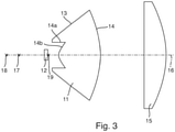
- figure 3 shows a vertical section through the arrangement figure 2 .
- the catadioptric primary optics 11 shown here has a refractive lens part in the center around the optical axis 16 and an outer reflecting part, which surrounds the lens section, with totally reflecting boundary surfaces 13 .
- One The light entrance surface of the reflecting part of the primary optics 11 is denoted by the reference numeral 14a and a light entrance surface of the central lens part of the primary optics 11 by the reference numeral 14b.
- the focal points 17, 18, 19 and their positions relative to one another and with respect to the semiconductor light source 12 can be clearly seen.
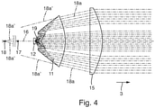
- FIG. 4 the optical system of the light module 10 is off figure 3 10 is shown with exemplary light rays traveling in the vertical plane and originating at the center of the light emitting surface of the semiconductor light source 12.
- the focal point 17 of the primary optics 11 is arranged between the focal point 18 and the semiconductor light source 12.
- the focal point 19 of the entire system is arranged on the light-emitting surface of the light source 12 .
- figure 6 shows a plan view of the light module 10 from FIGS Figures 1 to 4 . It can be clearly seen that there is practically no collimation of the light beams in the horizontal plane due to the secondary optics 15 . With this structure, a resulting light distribution 30 can be generated, as is the case, for example, in figure 7 is shown.
- figure 7 shows a measuring screen arranged at a distance (eg 25 m) in front of the motor vehicle or in front of the light module 10, on which a horizontal axis and a vertical axis are plotted, which intersect at one point.
- the light distribution 30 forms a sharp light-dark boundary 31 just below the 0° line (vertical) and can therefore be used as a low beam distribution or as part of it.
- Examples are lines with the same illuminance (so-called isolux lines) drawn in the light distribution 30 .
- a reference numeral 32 denotes a solid line for 10.0 lx, 33 a broken line for 1.0 lx, and 34 a chain line for 0.1 lx.
- Various criteria can be used to define the light-dark boundary 31 .
- the position of the 0.1 lx iso line 34 was used as a simple criterion.
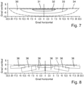
- figure 8 shows how the light distribution 30 is created by superimposing different images 36 of the light-emitting surface of the light source 12.
- the different segments or facets 13 of the boundary surfaces of the primary optics 11 are designed in such a way that the uppermost corner or edge of the image lies on the line that marks the target position of the light-dark boundary 31 .
- the light source 12 in this example is an LED, the luminous surface of which is square in shape
- all of the images 36 are rectangular in shape with widely differing lengths and widths.
- These images 36 result because the imaging of the system is anamorphic, ie the LED chip image 36 is enlarged differently in the horizontal and vertical directions. In the system described, the horizontal magnification is always greater than the vertical because the vertical focal length of the overall system is longer than the horizontal focal length.
- the second lens 15 is a cylindrical optic, it does not have a focal point, but rather a focal line. As a result, it is easily possible to use a plurality of first optics 11 in order, for example, to increase the luminous flux of the overall system. To do this, the additional optics must be placed on a line that runs parallel to the focal line.
- An example of a realization of such a system shows figure 9 .
- an optical system of a light module 10 is shown comprising three semiconductor light sources 12, three primary optics 11 assigned to them in the form of catadioptric optics, and secondary optics 15 in the form of a cylindrical lens.
- the cylindrical lens includes a focal line 18a.
- the light-emitting surfaces of the LEDs 12 are arranged on a line 19a, which preferably runs parallel to the focal line 18a of the secondary optics 15.
- the line 19a corresponds to a focal line of the entire optical system of the light module 10.
- the secondary optics 15 is designed in the form of a curved cylindrical lens in order to achieve an attractive design of the light exit surface of the light module 10 .
- the cylindrical lens 15 is bent in a horizontal plane.
- the curvature of the lens surface in the vertical section has remained constant.
- the focal length of the cylindrical lens 15 in the vertical section does not change, but the position and shape of the focal line 18a, which is now also bent in the horizontal plane, does.
- first optics 11 and second optics 15 thereby produces different horizontal and vertical magnifications and each first optics 11 must therefore be designed differently.
- the focal line 18a of the secondary optics 15 and the focal line 19a of the entire optical system no longer run parallel to one another.
- each optical subsystem (with elements 12, 11, 15) is intended to generate a comparable light distribution, as is the case, for example, with pixel-shaped light distributions for adaptive high beam distributions (e.g. partial high beam, marking light, etc.).
- each subsystem provides the same magnification of the images of the light-emitting surface of the semiconductor light sources 12 in the horizontal or vertical direction.
- the position of the LEDs 12 must be selected on a line 19a parallel to the focal line 18a of the secondary optics 15.
- a corresponding example is in figure 12 shown.
- a light distribution 30 with a horizontal light-dark boundary 31 (cf. figure 7 ) generated.
- the invention can also be used to generate light distributions with horizontal and/or vertical or arbitrarily shaped and/or aligned light-dark boundaries by positioning the corners of the LED chip images along predetermined lines, with the lines then forming the light-dark boundaries of the light distribution .
- figure 13 shows an example of how the LED chip images 41 of different areas 13 of a first optics 11 can be positioned in order to generate a strip-shaped light distribution 40 with vertical light-dark borders 42 and horizontal light-dark borders 43 .
- FIGS. 14 to 21 show examples of a total of 21 individual light distributions 50, which can each be generated by an LED 12 with associated first optics 11 and the second optics 15 in the form of a cylindrical lens.
- figure 14 shows the individual light distributions 50 of LEDs #1 to #3, figure 15 from LEDs #4 to #6, figure 16 from LEDs #7 to #9, figure 17 of LEDs #10 and #11, figure 18 from LEDs #12 to #14, figure 19 from LEDs #15 to #17, figure 20 from LEDs #18 to #20 and figure 21 from LED #21.
- the individual light distributions 50 each have two vertical light-dark boundaries 51 and two horizontal light-dark boundaries 52 . This illuminates a defined angular range horizontally and vertically. Lines with the same illuminance levels (so-called isolux lines) are drawn in the individual light distributions 50 by way of example.
- a solid line for 50.0 lx is denoted by reference numeral 53, a broken line for 10 lx by 54, and a chain line for 0.1 lx by 55.
- Various criteria can be used to define the light-dark boundaries 51, 52. In the example shown, the position of the 0.1 lx iso line 55 was used as a simple criterion. Based on this definition, the illuminated angular range is approximately 3° wide horizontally and 10° vertically high.
- the in figure 22 shown resulting light distribution 60, which can serve as a high beam distribution.
- Lines with the same illuminance levels are drawn in the light distribution 60 by way of example.
- a solid line for 50.0 lx is denoted by reference numeral 61, a broken line for 10 lx by 62 and a broken line for 0.1 lx by 63. Since the individual light distributions 50 are each offset horizontally by approx. 1.5° from one another, 12 angle areas with a minimum width of approx. 1.5° can be switched dark by deactivating or dimming individual LEDs.
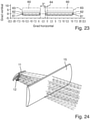
- An example of an overall light distribution 60 with two times 1.5° wide dark blanking area 64 is shown figure 23 .
- the motor vehicle in which headlights 1 with the light module 10 according to the invention are installed has suitable means for detecting other road users in front of the motor vehicle. These means include, for example, a video camera for recording images of the area in front of the motor vehicle and a computing unit for evaluating the recorded images and for detecting oncoming vehicles or vehicles driving ahead in a specific area of the images.
- the area of the high beam distribution 60 off figure 22 is specifically darkened or hidden by deactivating or dimming certain LEDs 12 in order to prevent road users from being dazzled.
- the high beam can remain switched on in all other areas of light distribution 60 in order to ensure good visibility for the driver of the motor vehicle.
- the blanking area 64 can change dynamically, for example when another oncoming road user drives past the motor vehicle with the light module 10 or when a preceding road user is driving in front of the motor vehicle on a winding road.
- the width of the blanking area 64 can be individually adapted to the current traffic situation.
- the LEDs 12 are typically energized in a pulse width modulated manner.
- the luminous flux can be controlled by changing the pulse width.
- the first optics 11 is implemented as a reflector and the second optics 15 as a cylindrical lens.
- the second optics 15 it is advantageous to implement it with a plurality of LEDs 12, associated reflectors 11 and a cylindrical lens 15, as in figure 25 shown.
- a low beam distribution 80 with an asymmetrical (bent) light-dark boundary 81 can be generated from this, for example, as is shown, for example, in figure 30 is shown.
- the Figures 26 to 29 show individual light distributions 70 which are generated by subsystems #1 to #5, each comprising an LED 12, a reflector 11 and the cylindrical lens 15.
- Subsystems #1 to #3 produce, for example, light distributions 70 with a horizontal light-dark boundary 71 that is just below 0° vertically (cf. Figures 26 to 28 ). Lines with the same illuminance levels (so-called isolux lines) are drawn in the individual light distributions 70 by way of example.
- a solid line for 4.0 lx is denoted by 72, a broken line for 0.4 lx by 73 and a dashed line for 0.1 lx denoted by 74.
- Various criteria can be used to define the light-dark boundary 71 .
- the position of the 0.1 lx iso line 74 was used as a simple criterion.
- FIG 26 is the individual light distribution 70 generated by subsystem #1, in figure 27 those through subsystem #2 and in figure 28 the individual light distribution 70 produced by subsystem #3 is shown.
- figure 29 1 shows an individual light distribution 70 as produced by subsystem #4 (LED #4, reflector #4 and cylindrical lens 15) and subsystem #5 (LED #5, reflector #5 and cylindrical lens 15) of light module 10, respectively figure 25 is produced.
- the light distribution 70 has a light-dark boundary 71a that rises obliquely from the center (point of intersection of the horizontal and the vertical) to the top right (towards one's own traffic side).
- the illuminance distribution in the light distributions 70 is illustrated by iso-lines.
- a solid line for 4.0 lx is denoted by reference numeral 72, a broken line for 1.0 lx by 73a, and a chain line for 0.1 lx by 74.
- FIG. Of course, these values for the illuminance are only selected as examples and in practice they can deviate from the values given here.
- figure 30 shows the resulting total light distribution 80 of the light module 10 in the form of a low beam distribution with an asymmetrical light-dark boundary 81.
- the light distribution 80 results from a superimposition of the individual light distributions 70 of the LEDs #1 to #5 from FIGS Figures 26 to 29 .
- the light-dark boundary 81 of the light distribution 80 has an incline approximately from the center (point of intersection of the horizontal and the vertical) to the top right (towards one's own traffic side). rising section 81a.
- the illuminance distribution in the light distributions 80 is illustrated by iso-lines.
- a reference numeral 82 is a solid line for 10.0 lx
- 83a is a broken line for 1.0 lx
- 84 is a chain line for 0.1 lx.
- a further variant is that a plurality of LEDs 12 each use a first optics 11 .
- the number of generated light areas ("pixels") of an adaptive high beam distribution can be increased without the number of first optics 11 having to be increased.
Description
Die vorliegende Erfindung betrifft ein Lichtmodul für einen Kraftfahrzeugscheinwerfer nach dem Oberbegriff des Anspruchs 1. Ein solches Lichtmodul ist aus der Druckschrift
- mindestens eine Primäroptik zum Bündeln zumindest eines Teils des abgestrahlten Lichts, und
- eine Sekundäroptik zur weiteren Bündelung des von der mindestens einen ersten Optik bereits gebündelten Lichts und zur Erzeugung einer resultierenden Lichtverteilung des Lichtmoduls auf einer Fahrbahn vor dem Kraftfahrzeug umfasst, ist bspw. aus der
DE 10 2005 015 007 A1 US 2014/0092619 A1
- at least one primary optics for focusing at least part of the emitted light, and
- secondary optics for further bundling of the light already bundled by the at least one first optic and for generating a resulting light distribution of the light module on a roadway in front of the motor vehicle is, for example, from
DE 10 2005 015 007 A1 US 2014/0092619 A1
Ferner ist aus der
Aus der
Die Linsen bilden ein abbildendes optisches System aus rotationssymmetrischen Linsen. Die Lichtaustrittsfläche ist grundsätzlich durch die Form einer Linse gegeben, also durch eine in etwa kreisrunde Fläche. Eine Abweichung von dieser Form beeinträchtigt unmittelbar die Lichtausbeute und die Qualität der Lichtverteilung. Eine Verbreiterung der Lichtaustrittsfläche lässt sich außerdem nur durch Vergrößerung der Mittendicke der zweiten Optik erreichen. Dies bedeutet aber auch wieder, dass schnell Mittendicken von > 20mm entstehen, die zu längeren Zykluszeiten und erhöhten Herstellungskosten führen.The lenses form an imaging optical system made up of rotationally symmetrical lenses. The light exit surface is basically given by the shape of a lens, i.e. by an approximately circular surface. Any deviation from this shape directly affects the luminous efficacy and the quality of the light distribution. A broadening of the light exit surface can also only be achieved by increasing the center thickness of the second lens. However, this also means that center thicknesses of > 20mm quickly arise, which lead to longer cycle times and increased manufacturing costs.
Durch die vorliegende Erfindung soll die Größe des Lichtmoduls, insbesondere in Lichtaustrittsrichtung verringert werden. Gleichzeitig soll die Lichtaustrittsfläche des Lichtmoduls ohne Einbußen beim Wirkungsgrad variiert und die Herstellung der Optiken des Lichtmoduls besonders kostengünstig realisiert werden können.The present invention is intended to reduce the size of the light module, in particular in the light exit direction. At the same time, the light exit surface of the light module should be varied without sacrificing efficiency and the production of the optics of the light module should be able to be implemented particularly cost-effectively.
Zur Lösung dieser Aufgabe wird ein Lichtmodul mit den Merkmalen des Anspruchs 1 vorgeschlagen.To solve this problem, a light module with the features of
Die beschriebenen Mängel des Standes der Technik werden durch die Erfindung dadurch beseitigt, dass die Lichtverteilung aus einem optischen System von mindestens einer dünnwandigen ersten Optik (Primäroptik) und einer dünnwandigen zweiten Optik (Sekundäroptik) realisiert wird. Eine Optik wird hier als dünnwandig bezeichnet, wenn sie eine maximale Mittendicke von <20mm aufweist. Alle ersten Optiken teilen sich eine gemeinsame zweite Optik. Alle Optiken sind astigmatische Optiken, die in einer vertikalen und einer horizontalen Ebene deutlich unterschiedliche Brennweiten aufweisen. Ein optisches System umfassend mindestens eine Primäroptik und die Sekundäroptik bildet eine anamorphe Abbildung der leuchtenden Fläche der mindestens einen Halbleiterlichtquelle. Die anamorphe Abbildung bewirkt, dass in den horizontalen und vertikalen Ebenen unterschiedliche Vergrößerungen und damit unterschiedliche Ausdehnungen des Strahlkegels, der durch die Halbleiterlichtquelle erzeugt wird, entstehen. Durch eine geeignete Auslegung der vertikalen und horizontalen Brennweiten der Optiken wird es möglich, die Lichtaustrittsfläche der zweiten Optik und damit des Lichtmoduls in zwei zueinander senkrechten Richtungen mit unterschiedlicher Ausdehnung zu gestalten, ohne dass dies auf Kosten der Lichtausbeute geht. Die Aufteilung von einer auf zwei oder mehr Optiken ermöglicht zudem die Realisierung einer hohen numerischen Apertur bei gleichzeitig großer Brennweite bzw. geringer Vergrößerung ohne dass dafür dickwandige (> 20mm Mittendicke) Optiken benötigt werden, die aufwändige und zeitintensive Herstellungsprozesse benötigen und daher nicht kostengünstig herzustellen sind. Die hohe numerische Apertur und große Brennweite haben zur Folge, dass sowohl eine hohe optische Effizienz (= Lichtausbeute) als auch eine hohe Beleuchtungsstärke in der Bildebene des Lichtmoduls erzielt werden können.The described deficiencies of the prior art are eliminated by the invention in that the light distribution is realized from an optical system of at least one thin-walled first lens (primary lens) and a thin-walled second lens (secondary lens). An optic is referred to as thin-walled if it has a maximum central thickness of <20mm. All first optics share a common second optic. All optics are astigmatic optics that have significantly different focal lengths in a vertical and a horizontal plane. An optical system comprising at least one primary optics and the secondary optics forms an anamorphic image of the luminous surface at least one semiconductor light source. The anamorphic imaging causes different enlargements and thus different expansions of the beam cone generated by the semiconductor light source in the horizontal and vertical planes. A suitable design of the vertical and horizontal focal lengths of the optics makes it possible to design the light exit surface of the second optics and thus of the light module in two mutually perpendicular directions with different dimensions, without sacrificing the light yield. The division from one to two or more optics also enables the realization of a high numerical aperture with a large focal length or low magnification at the same time without the need for thick-walled (> 20mm middle thickness) optics that require complex and time-consuming manufacturing processes and are therefore not inexpensive to produce . The high numerical aperture and large focal length mean that both high optical efficiency (= luminous efficacy) and high illuminance in the image plane of the light module can be achieved.
Die ersten Optiken dienen zum Bündeln des Lichts in einem ersten Schritt und zur Lichtformung. Sie können daher unterschiedlich geformte Bereiche (Segmente oder Facetten) aufweisen, um Licht, das auf die verschiedenen Bereiche trifft, in unterschiedliche Positionen in der Bildebene zu lenken. Eine derartige katadioptrische Vorsatzoptik ist grundsätzlich aus der
Die Halbleiterlichtquelle, die einer ersten Optik zugeordnet ist, erzeugt durch das optische System bestehend aus erster und zweiter Optik eine Lichtverteilung, die eine oder mehrere beliebig geformte Helldunkelgrenzen aufweisen kann. Die resultierende Gesamtlichtverteilung des Lichtmoduls ergibt sich aus der Überlagerung der Einzellichtlichtverteilungen, die durch jeweils eine Lichtquelle eine zugeordnete Primäroptik und eine Sekundäroptik erzeugt wird. Jede Einzellichtverteilung kann eine unterschiedliche Form der Lichtverteilungen und der Helldunkelgrenzen aufweisen, indem die jeweils erste Optik unterschiedlich ausgeführt wird oder die Art, Form oder Lage der Halbleiterlichtquelle unterschiedlich gewählt wird.The semiconductor light source, which is assigned to a first optic, generates a light distribution through the optical system consisting of the first and second optics, which can have one or more light-dark boundaries of any shape. The resulting overall light distribution of the light module results from the superimposition of the individual light distributions, which is generated by a light source, an associated primary optics and a secondary optics. Each individual light distribution can have a different shape of the light distributions and the light-dark boundaries, in that the respective first optics are designed differently or the type, shape or position of the semiconductor light source is selected differently.
Wenn die Primäroptik als eine katadioptrische Vorsatzoptik aus einem transparenten Material ausgebildet ist, können die Lichteintritts- und/oder Lichtaustrittsflächen eine wellen- oder kissenförmige Modulation aufweisen, die dazu dient, das Licht in einer oder mehreren Richtungen zu streuen. Diese Streuung dient dazu, die Lichtverteilung breiter zu gestalten oder bzgl. Intensität oder Farberscheinung zu homogenisieren.If the primary optics are embodied as catadioptric attachment optics made of a transparent material, the light entry and/or light exit surfaces can have a wavy or pincushion-shaped modulation that serves to scatter the light in one or more directions. This scattering serves to make the light distribution broader or to homogenize it in terms of intensity or color appearance.
Die Sekundäroptik dient optisch ausschließlich einer weiteren Fokussierung des Lichts, vorzugsweise in nur einer Ebene. Sie bildet die Lichtaustrittsfläche des optischen Systems des Lichtmoduls und weist im Gegensatz zur ersten Optik keine sichtbaren unterschiedlichen Bereiche zur Lichtformung auf. Alle ersten Optiken teilen sich die zweite Optik, d.h. alle optischen Achsen der Teilsysteme aus Lichtquellen und zugeordneten ersten Optiken verlaufen durch die zweite Optik. Typischerweise ist die Brennweite der zweiten Optik in einer ersten Ebene größer als 100mm und damit größer als die Länge des optischen Systems in Lichtaustrittsrichtung, gemessen entlang einer optischen Achse von der Lichtquelle bis zu der Lichtaustrittsfläche der zweiten Optik. Die Brennweite in der dazu senkrechten zweiten Ebene ist deutlich größer, typischerweise unendlich. Das bewirkt, dass eine Verbreiterung der zweiten Optik in der Richtung, die in der zweiten Ebene und senkrecht zur optischen Achse liegt, wenig Auswirkung auf die Qualität der Lichtverteilung hat, da sich die Vergrößerung des Gesamtsystems aus erster und zweiter Optik dadurch nicht ändert. Das wiederum heißt, dass z.B. die Breite einer Zylinderlinse flexibel an gestalterische Vorgaben angepasst werden kann. Insbesondere kann z.B. die Breite merklich größer als die Höhe gestaltet werden, was bei einem herkömmlichen nicht-anamorphen optischen System, bestehend aus rotationssymmetrischen Einzeloptiken nicht möglich ist.The secondary optics serves optically exclusively for further focusing of the light, preferably in only one plane. It forms the light exit surface of the optical system of the light module and, in contrast to the first optic, has no visible different areas for light shaping. All of the first optics share the second optics, ie all optical axes of the subsystems made up of light sources and associated first optics run through the second optics. Typically, the focal length of the second optics in a first plane is greater than 100mm and thus greater than the length of the optical system in Light exit direction, measured along an optical axis from the light source to the light exit surface of the second lens. The focal length in the second plane perpendicular thereto is significantly greater, typically infinite. As a result, widening the second optics in the direction that lies in the second plane and perpendicular to the optical axis has little effect on the quality of the light distribution, since the magnification of the overall system of first and second optics does not change as a result. This in turn means that, for example, the width of a cylindrical lens can be flexibly adapted to design specifications. In particular, for example, the width can be made noticeably larger than the height, which is not possible with a conventional non-anamorphic optical system consisting of rotationally symmetrical individual optics.
Vorteilhafte Weiterbildungen und weitere bevorzugte Ausführungsbeispiele der vorliegenden Erfindung können den Unteransprüchen sowie der nachfolgenden Figurenbeschreibung und den dazugehörigen Figuren entnommen werden. Es zeigen:
Figur 1- ein erfindungsgemäßes Lichtmodul gemäß einer bevorzugten Ausführungsform in einer perspektivischen Ansicht;
Figur 2- das Lichtmodul aus
Figur 1 Figur 3- einen Vertikalschnitt durch das Lichtmodul aus
Figur 1 Figur 4- das Lichtmodul aus
Figur 3 Figur 5- eine Draufsicht auf eine Lichtaustrittsfläche einer ersten Optik des Lichtmoduls aus
den Figuren 1 ;bis 4 Figur 6- einen Horizontalschnitt durch das
Lichtmodul aus Figur 1 mit beispielhaft eingezeichneten Lichtstrahlen, die von der Licht emittierenden Fläche der Halbleiterlichtquelle des Lichtmoduls ausgesandt wurden; - Figur 7
- einen in Lichtaustrittsrichtung des Lichtmoduls in einem Abstand zu dem Lichtmodul angeordneten Messschirm mit einer darauf abgebildeten resultierenden Lichtverteilung des Lichtmoduls mit einer horizontalen Helldunkelgrenze;
Figur 8- den Messschirm aus
Figur 7 mit einer Veranschaulichung des Prinzips, wie die Helldunkelgrenze erzeugt wird; Figur 9- ein erfindungsgemäßes Lichtmodul gemäß einer anderen bevorzugten Ausführungsform in einer perspektivischen Ansicht;
Figur 10- ein erfindungsgemäßes Lichtmodul gemäß einer weiteren bevorzugten Ausführungsform in einer Draufsicht;
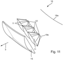
Figur 11- das
Lichtmodul aus Figur 10 in einer perspektivischen Ansicht; Figur 12- ein erfindungsgemäßes Lichtmodul gemäß noch einer weiteren bevorzugten Ausführungsform in einer Draufsicht;
Figur 13- einen in Lichtaustrittsrichtung des Lichtmoduls in einem Abstand zu dem Lichtmodul angeordneten Messschirm mit einer darauf abgebildeten streifenförmigen resultierenden Lichtverteilung des Lichtmoduls mit vertikalen und horizontalen Helldunkelgrenzen;
Figur 14- übereinander verschiedene Messschirme mit verschiedenen Lichtverteilungen, die
von den Lichtquellen 1bis 3 des Lichtmoduls erzeugt wurden; Figur 15- übereinander verschiedene Messschirme mit verschiedenen Lichtverteilungen, die
von den Lichtquellen 4bis 6 des Lichtmoduls erzeugt wurden; Figur 16- übereinander verschiedene Messschirme mit verschiedenen Lichtverteilungen, die von den Lichtquellen 7
bis 9 des Lichtmoduls erzeugt wurden; Figur 17- übereinander verschiedene Messschirme mit verschiedenen Lichtverteilungen, die
von den Lichtquellen 10 und 11 des Lichtmoduls erzeugt wurden; Figur 18- übereinander verschiedene Messschirme mit verschiedenen Lichtverteilungen, die
von den Lichtquellen 12bis 14 des Lichtmoduls erzeugt wurden; Figur 19- übereinander verschiedene Messschirme mit verschiedenen Lichtverteilungen, die
von den Lichtquellen 15bis 17 des Lichtmoduls erzeugt wurden; Figur 20- übereinander verschiedene Messschirme mit verschiedenen Lichtverteilungen, die
von den Lichtquellen 18bis 20 des Lichtmoduls erzeugt wurden; Figur 21- einen Messschirm mit einer Lichtverteilung, die
von der Lichtquelle 21 des Lichtmoduls erzeugt wurde; Figur 22- einen Messschirm mit einer resultierenden Gesamtlichtverteilung des Lichtmoduls,
wenn alle Lichtquellen 1bis 21aus den Figuren 14 eingeschaltet sind;bis 21 Figur 23- einen Messschirm mit einer resultierenden Gesamtlichtverteilung des Lichtmoduls, wenn bis auf die
Lichtquellen 13 und 14alle Lichtquellen 1bis 21aus den Figuren 14 eingeschaltet sind;bis 21 - Figur 24
- ein Lichtmodul gemäß einer weiteren bevorzugten Ausführungsform in einer perspektivischen Ansicht mit beispielhaft eingezeichneten Lichtstrahlen;
Figur 25- ein Lichtmodul gemäß noch einer weiteren bevorzugten Ausführungsform in einer perspektivischen Ansicht;
- Figur 26
- einen Messschirm mit einer Lichtverteilung, die von dem
optischen Teilsystem # 1aus Figur 25 mitder Lichtquelle # 1,einem Reflektor # 1 und der Sekundäroptik des Lichtmoduls erzeugt wurde; - Figur 27
- einen Messschirm mit einer Lichtverteilung, die von dem
optischen Teilsystem # 2aus Figur 25 mitder Lichtquelle # 2,einem Reflektor # 2 und der Sekundäroptik des Lichtmoduls erzeugt wurde; - Figur 28
- einen Messschirm mit einer Lichtverteilung, die von dem
optischen Teilsystem # 3aus Figur 25 mitder Lichtquelle # 3,einem Reflektor # 3 und der Sekundäroptik des Lichtmoduls erzeugt wurde; - Figur 29
- einen Messschirm mit einer Lichtverteilung, die von dem
optischen Teilsystem # 4aus Figur 25 mitder Lichtquelle # 4,einem Reflektor # 4 und der Sekundäroptik des Lichtmoduls und demoptischen Teilsystem # 5aus Figur 25 mitder Lichtquelle # 5,einem Reflektor # 5 und der Sekundäroptik des Lichtmoduls erzeugt wurde; Figur 30- einen Messschirm mit einer resultierenden Gesamtlichtverteilung des Lichtmoduls, die sich aus einer Überlagerung der Einzellichtverteilungen gemäß der
Figuren 26 bis 29 ergibt; und Figur 31- einen Kraftfahrzeugscheinwerfer mit einem erfindungsgemäßen Lichtmodul.
- figure 1
- a light module according to the invention according to a preferred embodiment in a perspective view;
- figure 2
- the light module off
figure 1 with light beams drawn in by way of example, which were emitted by a light-emitting surface of a semiconductor light source of the light module; - figure 3
- a vertical section through the light module
figure 1 ; - figure 4
- the light module off
figure 3 with light rays drawn in by way of example, which originate in the middle of the light-emitting surface of the semiconductor light source of the light module; - figure 5
- a plan view of a light exit surface of a first optics of the light module from the
Figures 1 to 4 ; - figure 6
- a horizontal section through the light module
figure 1 with light rays drawn in by way of example, which were emitted from the light-emitting surface of the semiconductor light source of the light module; - figure 7
- a measuring screen arranged at a distance from the light module in the light exit direction of the light module, with a resulting light distribution of the light module imaged thereon with a horizontal light-dark boundary;
- figure 8
- off the measuring screen
figure 7 with an illustration of the principle of how the chiaroscuro is generated; - figure 9
- a light module according to the invention according to another preferred embodiment in a perspective view;
- figure 10
- a light module according to the invention according to a further preferred embodiment in a plan view;
- figure 11
- the light module off
figure 10 in a perspective view; - figure 12
- a light module according to the invention according to yet another preferred embodiment in a plan view;
- figure 13
- a measuring screen which is arranged at a distance from the light module in the light exit direction of the light module and has a strip-shaped resulting light distribution of the light module imaged thereon with vertical and horizontal light-dark boundaries;
- figure 14
- stacked different measuring screens with different light distributions, which were generated by the
light sources 1 to 3 of the light module; - figure 15
- different measuring screens with different light distributions, one above the other, which were generated by the
light sources 4 to 6 of the light module; - figure 16
- stacked different measuring screens with different light distributions, which were generated by the light sources 7 to 9 of the light module;
- figure 17
- stacked different measuring screens with different light distributions, which were generated by the
light sources - figure 18
- different measuring screens with different light distributions, generated by the
light sources 12 to 14 of the light module, one above the other became; - figure 19
- stacked different measuring screens with different light distributions, which were generated by the
light sources 15 to 17 of the light module; - figure 20
- stacked different measuring screens with different light distributions, which were generated by the
light sources 18 to 20 of the light module; - figure 21
- a measuring screen with a light distribution generated by the
light source 21 of the light module; - figure 22
- a measuring screen with a resulting total light distribution of the light module when all
light sources 1 to 21 from theFigures 14 to 21 are turned on; - figure 23
- a measuring screen with a resulting total light distribution of the light module if, except for the
light sources light sources 1 to 21 from theFigures 14 to 21 are turned on; - figure 24
- a light module according to a further preferred embodiment in a perspective view with light rays drawn in by way of example;
- figure 25
- a light module according to yet another preferred embodiment in a perspective view;
- figure 26
- a measuring screen having a light distribution emitted from the
optical subsystem # 1figure 25 was created with thelight source # 1, areflector # 1 and the secondary optics of the light module; - figure 27
- a measuring screen having a light distribution emitted from
optical subsystem # 2figure 25 was created with thelight source # 2, areflector # 2 and the secondary optics of the light module; - figure 28
- a measuring screen having a light distribution emitted from
optical subsystem # 3figure 25 was created withlight source # 3, areflector # 3 and the secondary optics of the light module; - figure 29
- a measuring screen having a light distribution emitted from
optical subsystem # 4figure 25 with thelight source # 4, areflector # 4 and the secondary optics of the light module and theoptical subsystem # 5figure 25 was created with thelight source # 5, areflector # 5 and the secondary optics of the light module; - figure 30
- a measuring screen with a resulting overall light distribution of the light module, which results from a superimposition of the individual light distributions according to the
Figures 26 to 29 yields; and - figure 31
- a motor vehicle headlight with a light module according to the invention.
In
Scheinwerfer 1 umfasst ein Gehäuse 2, das vorzugsweise aus Kunststoff gefertigt ist. Das Gehäuse 2 weist in Lichtaustrittsrichtung 3 eine Lichtaustrittsöffnung 4 auf, die durch eine transparente Abdeckscheibe 5 verschlossen ist. Die Abdeckscheibe 5 kann zumindest bereichsweise mit optisch wirksamen Elementen (z.B. in Form von Zylinderlinsen oder Prismen) versehen sein (sog. Streuscheibe), um eine Streuung des hindurchtretenden Lichts insbesondere in horizontaler Richtung zu bewirken. Die Abdeckscheibe 5 kann aber auch ohne optisch wirksame Elemente als klare Scheibe ausgebildet sein. Im Inneren des Gehäuses 2 ist ein erfindungsgemäßes Lichtmodul 10 angeordnet. Das Lichtmodul 10 dient zur Erzeugung einer beliebigen resultierenden Fahrt-Lichtverteilung oder eines Teils davon, bspw. eines Abblendlichts, Fernlichts, adaptiven Fahrtlichts (Stadtlicht, Landstraßenlicht, Autobahnlicht, Teilfernlicht, Markierungslicht), Nebellichts oder ähnliches.
Zusammen mit dem Lichtmodul 10 können in dem Gehäuse 2 auch noch andere Lichtmodule zur Erzeugung einer beliebigen Fahrt-Lichtverteilung oder eines Teils davon, oder Leuchtenmodule zur Realisierung einer beliebigen Leuchtenfunktion (z.B. Blinklicht, Positionslicht, Standlicht, Tagfahrlicht, Standlicht, Rückfahrlicht, Bremslicht oder ähnliches) angeordnet sein. Das erfindungsgemäße Lichtmodul 10 wird nachfolgend anhand der
Ein erstes Beispiel eines Lichtmoduls 10 wird nachfolgend anhand der
Die zweite Optik oder Sekundäroptik 15 ist in dem in
Ein Brennpunkt 17 der Primäroptik 11 ist entgegen einer Lichtaustrittsrichtung betrachtet hinter der mindestens einen Halbleiterlichtquelle 12 angeordnet. Ferner ein Brennpunkt 18 oder eine Brennlinie 18a (vgl.
In
In
Da es sich bei der zweiten Linse 15 um eine Zylinderoptik handelt, besitzt sie keinen Brennpunkt, sondern eine Brennlinie. Dadurch ist es einfach möglich, mehrere erste Optiken 11 einzusetzen, um z.B. den Lichtstrom des Gesamtsystems zu erhöhen. Hierzu müssen die zusätzlichen Optiken auf einer Linie platziert werden, die parallel zu der Brennlinie verläuft. Ein Beispiel für eine Realisierung eines solchen Systems zeigt
In der nächsten beispielhaften Realisierung eines erfindungsgemäßen Lichtmoduls 10 gemäß der
Die beschriebene Realisierung kann nachteilhaft sein, wenn jedes optische Teilsystem (mit Elementen 12, 11, 15) eine vergleichbare Lichtverteilung erzeugen soll, wie es z.B. bei pixelförmigen Lichtverteilungen für adaptive Fernlichtverteilungen (z.B. Teilfernlicht, Markierungslicht, etc.) der Fall ist. In diesem Fall ist es vorteilhaft, wenn jedes Teilsystem in horizontaler bzw. vertikaler Richtung die gleiche Vergrößerung der Bilder der Licht emittierenden Fläche der Halbleiterlichtquellen 12 liefert. Um dies zu erreichen, muss die Lage der LEDs 12 auf einer Linie 19a parallel zur Brennlinie 18a der Sekundäroptik 15 gewählt werden. Ein entsprechendes Beispiel ist in
Mit den zuvor beschriebenen Realisierungen der vorliegenden Erfindung wurde eine Lichtverteilung 30 mit einer horizontalen Helldunkelgrenze 31 (vgl.
Wenn mehrere LEDs 12 mit zugehöriger erster Optik 11 verwendet werden und wenn die LEDs 12 einzeln schaltbar sind, dann können adaptive Fernlichtverteilungen als resultierende Gesamtlichtverteilung des Lichtmoduls 10 realisiert werden, bei denen unterschiedliche definierte Winkelbereiche der Lichtverteilung durch verschiedene LEDs 12 ausgeleuchtet oder dunkel gelassen werden können. Die
Die Einzellichtverteilungen 50 weisen jeweils zwei vertikale Helldunkelgrenzen 51 und zwei horizontale Helldunkelgrenzen 52 auf. Dadurch wird ein definierter Winkelbereich horizontal und vertikal beleuchtet. Beispielhaft sind Linien mit gleichen Beleuchtungsstärken (sog. Isoluxlinien) in den Einzellichtverteilungen 50 eingezeichnet. Eine durchgezogene Linie für 50,0 lx ist mit dem Bezugszeichen 53, eine gestrichelte Linie für 10 lx mit 54 und eine gestrichpunktete Linie für 0,1 lx mit 55 bezeichnet. Für die Definition der Helldunkelgrenzen 51, 52 können verschiedene Kriterien herangezogen werden. In dem gezeigten Beispiel wurde als einfaches Kriterium die Lage der 0,1 lx Iso-Linie 55 angewandt. Der ausgeleuchtete Winkelbereich ist anhand dieser Definition jeweils ungefähr horizontal 3° breit und vertikal 10° hoch.The individual
Wenn alle LEDs 12 gleichzeitig angeschaltet sind, so entsteht die in
Um die erzeugte Lichtverteilung 60 noch flexibler steuern zu können, ist es sinnvoll, den Lichtstrom über eine variable Leistungsversorgung steuern zu können. Typischerweise werden die LEDs 12 dazu pulsweitenmoduliert bestromt. Durch Änderung der Pulsweite kann der Lichtstrom gesteuert werden.In order to be able to control the generated
In einem anderen Ausführungsbeispiel, das in
In
Eine weitere Variante ist, dass jeweils mehrere LEDs 12 eine erste Optik 11 nutzen. Auf diese Weise kann z.B. die Zahl der erzeugten Lichtbereiche ("Pixel") einer adaptiven Fernlichtverteilung erhöht werden, ohne dass die Anzahl der ersten Optiken 11 erhöht werden muss.A further variant is that a plurality of
Claims (13)
- Light module (10) for a vehicle headlight (1), comprising- at least one semiconductor light source (12) with a light-emitting surface for radiating light,- at least one primary optics (11) for consolidating at least a portion of the emitted light, whereby the primary optics (11) comprises a focus (17) behind the at least one semiconductor light source (12) from the perspective of the light output direction (3),- a secondary optics (15) for further consolidation of the light already consolidated by the at least one primary optics (11) and for inducing a subsequent light distribution (30; 40; 60; 80) of the light module (10) on a road lane in front of the vehicle, whereby the secondary optics (15) comprises a focus (18) or a focal line (18a) behind the at least one semiconductor light source (12) from the perspective of the light output direction (3), and whereby- the entire optical system of the light module (10), comprising the at least one primary optics (11) and the secondary optics (15), comprises a focus (19) or a focal line (19a) near the light-emitting surface of the at least one semiconductor light source (12),characterised in that the primary optics (11) is designed as a catadioptric optics comprising a maximum centre thickness less than 20 mm and comprising differently shaped areas (13) in the form of reflecting segments or facets, whereby each of these areas (13) reflects light from the at least one semiconductor light source (12) to create a sub-area (36; 41; 50; 70) of the light distribution (30; 40; 60; 80) and the subsequent light distribution (30; 40; 60; 80) is caused by an overlap of the sub-areas (36; 41; 50; 70) of the light distribution (30; 40; 60; 80) of the various areas (13) of the primary optics (11), whereby the secondary optics comprises a maximum centre thickness less than 20 mm and forms the light output surface of the optic system of the light module and, contrary to the primary optics, does not comprise any visible areas for forming light, and whereby all optics are astigmatic optics comprising widely varying focal distances in a vertical and horizontal plane.
- Light module (10) as per claim 1, characterised in that the at least one primary optics (11) is an optical attachment made from a transparent material comprising at least one light input surface, multiple fully reflective marginal surfaces, and at least one light output surface (14), and that consolidates the light from the at least one semiconductor light source (12) via refraction during intake into the optical attachment and/or output from the optical attachment, and via internal total reflection on the marginal surfaces.
- Light module (10) as per claim 2, characterised in that at least one of the light output surfaces (14) of the at least one primary optics (11) comprises a wave- or pincushion-shaped modulation.
- Light module as per claim 1 or 2, characterised in that the secondary optics (15) is shaped such that it consolidates the light in a first plane comprising an optical axis (16) of the optical system of the light module (10) more strongly than in a second plane comprising an optical axis (16) of the optical system of the light module (10) that is perpendicular to the first plane.
- Light module (10) as per claim 4, characterised in that the secondary optics (15) in the first plane is far shorter than in the second plane.
- Light module (10) as per claim 5, characterised in that the secondary optics (15) is designed as a cylinder lens, the cylinder axis (18a) of which runs along the second plane or parallel to it.
- Light module (10) as per claim 1 or 2, characterised in that the light distribution (30; 40; 60; 80) of the light module (10) after passing through the secondary optics (15) results from an overlap of the sub-areas (36; 41; 50; 70) of the light distribution (30; 40; 60; 80) of the various areas (13) of the primary optics (11).
- Light module (10) as per one of the claims 1 through 7, characterised in that the at least one primary optics (11) and the secondary optics (15) are attuned with one another with regard to arrangement and configuration such that the resulting light distribution of the light module (10) is a screened light distribution (30) in the form of a dim light or fog light distribution with a horizontal cutoff line (31), or a striped light distribution (40) with vertical and horizontal cutoff lines (41, 42), or a partial full beam light distribution (60; 80) with vertical and horizontal cutoff lines.
- Light module (10) as per one of the claims 1 through 8, characterised in that the light module (10) comprises multiple semiconductor light sources (12), the light-emitting surfaces of which are arranged on one line (19a) or plane.
- Light module (10) as per claim 9, characterised in that the line (19a) or plane where the light-emitting surfaces of the semiconductor light sources (12) are arranged runs parallel to a focal line (18a) of the secondary optics (15) .
- Light module (10) as per claim 9, characterised in that the line (19a) or the plane where the light-emitting surfaces of the semiconductor light sources (12) are located is arched.
- Light module (10) as per one of the claims 9 through 11, characterised in that the light module (10) comprises multiple semiconductor light sources (12) that can be individually turned off, turned on, and dimmed.
- Light module (10) as per one of the claims 9 through 12, characterised in that at least two of the semiconductor light sources (12) emit light to create various light distirbutions, and the semiconductor light sources (12) are individually turned off, turned on, or dimmed to toggle between the light distirbutions.
Applications Claiming Priority (1)
| Application Number | Priority Date | Filing Date | Title |
|---|---|---|---|
| DE102016118152.8A DE102016118152A1 (en) | 2016-09-26 | 2016-09-26 | Light module for a motor vehicle headlight |
Publications (2)
| Publication Number | Publication Date |
|---|---|
| EP3301350A1 EP3301350A1 (en) | 2018-04-04 |
| EP3301350B1 true EP3301350B1 (en) | 2022-02-23 |
Family
ID=59829256
Family Applications (1)
| Application Number | Title | Priority Date | Filing Date |
|---|---|---|---|
| EP17190034.3A Active EP3301350B1 (en) | 2016-09-26 | 2017-09-08 | Light module for a motor vehicle headlamp |
Country Status (2)
| Country | Link |
|---|---|
| EP (1) | EP3301350B1 (en) |
| DE (1) | DE102016118152A1 (en) |
Families Citing this family (5)
| Publication number | Priority date | Publication date | Assignee | Title |
|---|---|---|---|---|
| EP3550203B1 (en) * | 2018-04-04 | 2022-12-21 | ZKW Group GmbH | Light module for a swept-back motor vehicle lighting device |
| FR3084728B1 (en) * | 2018-07-31 | 2021-03-19 | Valeo Vision | LIGHT MODULE IMAGING THE ILLUMINATED SURFACE OF A COLLECTOR |
| CN212746315U (en) * | 2020-07-02 | 2021-03-19 | 华域视觉科技(上海)有限公司 | Lens unit, auxiliary low-beam module, lens, low-beam lighting module and vehicle |
| DE102021124722A1 (en) | 2021-09-24 | 2023-03-30 | Bartenbach Holding Gmbh | radiator |
| CN116221647B (en) * | 2023-05-08 | 2023-07-28 | 常州星宇车灯股份有限公司 | Car light high beam lighting system, lighting module and vehicle |
Family Cites Families (9)
| Publication number | Priority date | Publication date | Assignee | Title |
|---|---|---|---|---|
| FR2772111B1 (en) * | 1997-12-05 | 2000-02-25 | Valeo Vision | PROJECTOR WITH HYPERBOLIC REFLECTOR AND OPTICAL BLOCK COMPRISING SUCH A PROJECTOR |
| JP4391870B2 (en) | 2004-04-02 | 2009-12-24 | 株式会社小糸製作所 | Lighting fixtures for vehicles |
| JP4752626B2 (en) * | 2006-06-01 | 2011-08-17 | 市光工業株式会社 | Vehicle lighting |
| DE102008027320A1 (en) | 2008-06-07 | 2009-12-10 | Hella Kgaa Hueck & Co. | Headlamp for vehicle, has light coupling and decoupling surfaces formed such that LED light sources represent hotspots infinitely so that vertical and horizontal end regions of hotspots lie proximate to one another |
| DE102011078653B4 (en) | 2011-07-05 | 2013-12-12 | Automotive Lighting Reutlingen Gmbh | Attachment optics for the bundling of emitted light of at least one semiconductor light source |
| AT512711B1 (en) * | 2012-03-21 | 2014-08-15 | Zizala Lichtsysteme Gmbh | Light module for a motor vehicle and motor vehicle headlights |
| DE102012211613A1 (en) * | 2012-07-04 | 2014-01-09 | Automotive Lighting Reutlingen Gmbh | light module |
| US8733992B2 (en) | 2012-10-01 | 2014-05-27 | Osram Sylvania, Inc. | LED low profile linear front fog module |
| DE102014203335A1 (en) * | 2014-02-25 | 2015-08-27 | Automotive Lighting Reutlingen Gmbh | Light module of a motor vehicle headlight and headlights with such a light module |
-
2016
- 2016-09-26 DE DE102016118152.8A patent/DE102016118152A1/en not_active Withdrawn
-
2017
- 2017-09-08 EP EP17190034.3A patent/EP3301350B1/en active Active
Also Published As
| Publication number | Publication date |
|---|---|
| DE102016118152A1 (en) | 2018-03-29 |
| EP3301350A1 (en) | 2018-04-04 |
Similar Documents
| Publication | Publication Date | Title |
|---|---|---|
| EP2910847B1 (en) | Light module of a motor vehicle headlight and headlight with such a light module | |
| EP3301350B1 (en) | Light module for a motor vehicle headlamp | |
| EP2799762B1 (en) | Light module for a motor vehicle headlamp | |
| EP2893249B1 (en) | Lighting unit for a headlight | |
| DE112013007443B4 (en) | Headlamp for use in a vehicle | |
| EP2789901B1 (en) | Light module of a motor vehicle lighting device | |
| EP2799761B1 (en) | Light module for a motor vehicle headlamp | |
| EP2587125B1 (en) | Headlamp projection module for a motor vehicle | |
| EP3714205B1 (en) | Light module for a motor vehicle headlamp | |
| DE102011078653B4 (en) | Attachment optics for the bundling of emitted light of at least one semiconductor light source | |
| EP2505910B1 (en) | Motor vehicle headlamp with a semiconductor light source | |
| DE102014200368B4 (en) | Partial remote light projection light module for a motor vehicle headlight | |
| DE102014205994B4 (en) | Light module with semiconductor light source and attachment optics and motor vehicle headlight with such a light module | |
| EP2846077A2 (en) | Projection lens for use in an LED module of a motor vehicle headlight, and LED module and motor vehicle headlamp with such a projection lens | |
| EP2863108B1 (en) | LED module of a motor vehicle headlamp | |
| DE102016103288A1 (en) | Luminaire module especially for street lights | |
| DE102008036845B4 (en) | lighting device | |
| EP3765781B1 (en) | Light module for motor vehicle headlight | |
| EP2963334B1 (en) | Light conductor assembly for use in a lighting device of a motor vehicle and motor vehicle lighting device with such a light conductor assembly | |
| DE602004002016T2 (en) | Car headlights that can illuminate elevated traffic signs | |
| EP3719391B1 (en) | Partial high beam module for a motor vehicle headlight | |
| EP3870894B1 (en) | Light unit for a motor vehicle headlamp | |
| DE2033443A1 (en) | Lighting device, in particular for motor vehicles | |
| DE10310263A1 (en) | LED floodlight for asymmetrical illumination | |
| DE102016101730A1 (en) | Light module of a lighting device of a motor vehicle and lighting device with such a light module |
Legal Events
| Date | Code | Title | Description |
|---|---|---|---|
| PUAI | Public reference made under article 153(3) epc to a published international application that has entered the european phase |
Free format text: ORIGINAL CODE: 0009012 |
|
| STAA | Information on the status of an ep patent application or granted ep patent |
Free format text: STATUS: THE APPLICATION HAS BEEN PUBLISHED |
|
| AK | Designated contracting states |
Kind code of ref document: A1 Designated state(s): AL AT BE BG CH CY CZ DE DK EE ES FI FR GB GR HR HU IE IS IT LI LT LU LV MC MK MT NL NO PL PT RO RS SE SI SK SM TR |
|
| AX | Request for extension of the european patent |
Extension state: BA ME |
|
| STAA | Information on the status of an ep patent application or granted ep patent |
Free format text: STATUS: REQUEST FOR EXAMINATION WAS MADE |
|
| 17P | Request for examination filed |
Effective date: 20181004 |
|
| RBV | Designated contracting states (corrected) |
Designated state(s): AL AT BE BG CH CY CZ DE DK EE ES FI FR GB GR HR HU IE IS IT LI LT LU LV MC MK MT NL NO PL PT RO RS SE SI SK SM TR |
|
| STAA | Information on the status of an ep patent application or granted ep patent |
Free format text: STATUS: REQUEST FOR EXAMINATION WAS MADE |
|
| RIC1 | Information provided on ipc code assigned before grant |
Ipc: F21S 41/26 20180101AFI20210720BHEP Ipc: F21S 41/265 20180101ALI20210720BHEP Ipc: F21S 41/143 20180101ALI20210720BHEP Ipc: F21S 41/148 20180101ALI20210720BHEP Ipc: F21S 41/33 20180101ALI20210720BHEP Ipc: F21V 5/00 20180101ALI20210720BHEP |
|
| GRAP | Despatch of communication of intention to grant a patent |
Free format text: ORIGINAL CODE: EPIDOSNIGR1 |
|
| STAA | Information on the status of an ep patent application or granted ep patent |
Free format text: STATUS: GRANT OF PATENT IS INTENDED |
|
| INTG | Intention to grant announced |
Effective date: 20210914 |
|
| GRAS | Grant fee paid |
Free format text: ORIGINAL CODE: EPIDOSNIGR3 |
|
| GRAA | (expected) grant |
Free format text: ORIGINAL CODE: 0009210 |
|
| STAA | Information on the status of an ep patent application or granted ep patent |
Free format text: STATUS: THE PATENT HAS BEEN GRANTED |
|
| AK | Designated contracting states |
Kind code of ref document: B1 Designated state(s): AL AT BE BG CH CY CZ DE DK EE ES FI FR GB GR HR HU IE IS IT LI LT LU LV MC MK MT NL NO PL PT RO RS SE SI SK SM TR |
|
| REG | Reference to a national code |
Ref country code: GB Ref legal event code: FG4D Free format text: NOT ENGLISH |
|
| REG | Reference to a national code |
Ref country code: CH Ref legal event code: EP |
|
| REG | Reference to a national code |
Ref country code: DE Ref legal event code: R096 Ref document number: 502017012630 Country of ref document: DE |
|
| REG | Reference to a national code |
Ref country code: AT Ref legal event code: REF Ref document number: 1470735 Country of ref document: AT Kind code of ref document: T Effective date: 20220315 |
|
| REG | Reference to a national code |
Ref country code: IE Ref legal event code: FG4D Free format text: LANGUAGE OF EP DOCUMENT: GERMAN |
|
| REG | Reference to a national code |
Ref country code: LT Ref legal event code: MG9D |
|
| REG | Reference to a national code |
Ref country code: NL Ref legal event code: MP Effective date: 20220223 |
|
| PG25 | Lapsed in a contracting state [announced via postgrant information from national office to epo] |
Ref country code: SE Free format text: LAPSE BECAUSE OF FAILURE TO SUBMIT A TRANSLATION OF THE DESCRIPTION OR TO PAY THE FEE WITHIN THE PRESCRIBED TIME-LIMIT Effective date: 20220223 Ref country code: RS Free format text: LAPSE BECAUSE OF FAILURE TO SUBMIT A TRANSLATION OF THE DESCRIPTION OR TO PAY THE FEE WITHIN THE PRESCRIBED TIME-LIMIT Effective date: 20220223 Ref country code: PT Free format text: LAPSE BECAUSE OF FAILURE TO SUBMIT A TRANSLATION OF THE DESCRIPTION OR TO PAY THE FEE WITHIN THE PRESCRIBED TIME-LIMIT Effective date: 20220623 Ref country code: NO Free format text: LAPSE BECAUSE OF FAILURE TO SUBMIT A TRANSLATION OF THE DESCRIPTION OR TO PAY THE FEE WITHIN THE PRESCRIBED TIME-LIMIT Effective date: 20220523 Ref country code: NL Free format text: LAPSE BECAUSE OF FAILURE TO SUBMIT A TRANSLATION OF THE DESCRIPTION OR TO PAY THE FEE WITHIN THE PRESCRIBED TIME-LIMIT Effective date: 20220223 Ref country code: LT Free format text: LAPSE BECAUSE OF FAILURE TO SUBMIT A TRANSLATION OF THE DESCRIPTION OR TO PAY THE FEE WITHIN THE PRESCRIBED TIME-LIMIT Effective date: 20220223 Ref country code: HR Free format text: LAPSE BECAUSE OF FAILURE TO SUBMIT A TRANSLATION OF THE DESCRIPTION OR TO PAY THE FEE WITHIN THE PRESCRIBED TIME-LIMIT Effective date: 20220223 Ref country code: ES Free format text: LAPSE BECAUSE OF FAILURE TO SUBMIT A TRANSLATION OF THE DESCRIPTION OR TO PAY THE FEE WITHIN THE PRESCRIBED TIME-LIMIT Effective date: 20220223 Ref country code: BG Free format text: LAPSE BECAUSE OF FAILURE TO SUBMIT A TRANSLATION OF THE DESCRIPTION OR TO PAY THE FEE WITHIN THE PRESCRIBED TIME-LIMIT Effective date: 20220523 |
|
| PG25 | Lapsed in a contracting state [announced via postgrant information from national office to epo] |
Ref country code: PL Free format text: LAPSE BECAUSE OF FAILURE TO SUBMIT A TRANSLATION OF THE DESCRIPTION OR TO PAY THE FEE WITHIN THE PRESCRIBED TIME-LIMIT Effective date: 20220223 Ref country code: LV Free format text: LAPSE BECAUSE OF FAILURE TO SUBMIT A TRANSLATION OF THE DESCRIPTION OR TO PAY THE FEE WITHIN THE PRESCRIBED TIME-LIMIT Effective date: 20220223 Ref country code: GR Free format text: LAPSE BECAUSE OF FAILURE TO SUBMIT A TRANSLATION OF THE DESCRIPTION OR TO PAY THE FEE WITHIN THE PRESCRIBED TIME-LIMIT Effective date: 20220524 Ref country code: FI Free format text: LAPSE BECAUSE OF FAILURE TO SUBMIT A TRANSLATION OF THE DESCRIPTION OR TO PAY THE FEE WITHIN THE PRESCRIBED TIME-LIMIT Effective date: 20220223 |
|
| PG25 | Lapsed in a contracting state [announced via postgrant information from national office to epo] |
Ref country code: IS Free format text: LAPSE BECAUSE OF FAILURE TO SUBMIT A TRANSLATION OF THE DESCRIPTION OR TO PAY THE FEE WITHIN THE PRESCRIBED TIME-LIMIT Effective date: 20220623 |
|
| PG25 | Lapsed in a contracting state [announced via postgrant information from national office to epo] |
Ref country code: SM Free format text: LAPSE BECAUSE OF FAILURE TO SUBMIT A TRANSLATION OF THE DESCRIPTION OR TO PAY THE FEE WITHIN THE PRESCRIBED TIME-LIMIT Effective date: 20220223 Ref country code: SK Free format text: LAPSE BECAUSE OF FAILURE TO SUBMIT A TRANSLATION OF THE DESCRIPTION OR TO PAY THE FEE WITHIN THE PRESCRIBED TIME-LIMIT Effective date: 20220223 Ref country code: RO Free format text: LAPSE BECAUSE OF FAILURE TO SUBMIT A TRANSLATION OF THE DESCRIPTION OR TO PAY THE FEE WITHIN THE PRESCRIBED TIME-LIMIT Effective date: 20220223 Ref country code: EE Free format text: LAPSE BECAUSE OF FAILURE TO SUBMIT A TRANSLATION OF THE DESCRIPTION OR TO PAY THE FEE WITHIN THE PRESCRIBED TIME-LIMIT Effective date: 20220223 Ref country code: DK Free format text: LAPSE BECAUSE OF FAILURE TO SUBMIT A TRANSLATION OF THE DESCRIPTION OR TO PAY THE FEE WITHIN THE PRESCRIBED TIME-LIMIT Effective date: 20220223 Ref country code: CZ Free format text: LAPSE BECAUSE OF FAILURE TO SUBMIT A TRANSLATION OF THE DESCRIPTION OR TO PAY THE FEE WITHIN THE PRESCRIBED TIME-LIMIT Effective date: 20220223 |
|
| REG | Reference to a national code |
Ref country code: DE Ref legal event code: R097 Ref document number: 502017012630 Country of ref document: DE |
|
| PG25 | Lapsed in a contracting state [announced via postgrant information from national office to epo] |
Ref country code: AL Free format text: LAPSE BECAUSE OF FAILURE TO SUBMIT A TRANSLATION OF THE DESCRIPTION OR TO PAY THE FEE WITHIN THE PRESCRIBED TIME-LIMIT Effective date: 20220223 |
|
| PLBE | No opposition filed within time limit |
Free format text: ORIGINAL CODE: 0009261 |
|
| STAA | Information on the status of an ep patent application or granted ep patent |
Free format text: STATUS: NO OPPOSITION FILED WITHIN TIME LIMIT |
|
| 26N | No opposition filed |
Effective date: 20221124 |
|
| PG25 | Lapsed in a contracting state [announced via postgrant information from national office to epo] |
Ref country code: SI Free format text: LAPSE BECAUSE OF FAILURE TO SUBMIT A TRANSLATION OF THE DESCRIPTION OR TO PAY THE FEE WITHIN THE PRESCRIBED TIME-LIMIT Effective date: 20220223 |
|
| PG25 | Lapsed in a contracting state [announced via postgrant information from national office to epo] |
Ref country code: MC Free format text: LAPSE BECAUSE OF FAILURE TO SUBMIT A TRANSLATION OF THE DESCRIPTION OR TO PAY THE FEE WITHIN THE PRESCRIBED TIME-LIMIT Effective date: 20220223 |
|
| REG | Reference to a national code |
Ref country code: CH Ref legal event code: PL |
|
| GBPC | Gb: european patent ceased through non-payment of renewal fee |
Effective date: 20220908 |
|
| REG | Reference to a national code |
Ref country code: BE Ref legal event code: MM Effective date: 20220930 |
|
| PG25 | Lapsed in a contracting state [announced via postgrant information from national office to epo] |
Ref country code: LU Free format text: LAPSE BECAUSE OF NON-PAYMENT OF DUE FEES Effective date: 20220908 |
|
| PG25 | Lapsed in a contracting state [announced via postgrant information from national office to epo] |
Ref country code: LI Free format text: LAPSE BECAUSE OF NON-PAYMENT OF DUE FEES Effective date: 20220930 Ref country code: IT Free format text: LAPSE BECAUSE OF FAILURE TO SUBMIT A TRANSLATION OF THE DESCRIPTION OR TO PAY THE FEE WITHIN THE PRESCRIBED TIME-LIMIT Effective date: 20220223 Ref country code: IE Free format text: LAPSE BECAUSE OF NON-PAYMENT OF DUE FEES Effective date: 20220908 Ref country code: FR Free format text: LAPSE BECAUSE OF NON-PAYMENT OF DUE FEES Effective date: 20220930 Ref country code: CH Free format text: LAPSE BECAUSE OF NON-PAYMENT OF DUE FEES Effective date: 20220930 |
|
| PG25 | Lapsed in a contracting state [announced via postgrant information from national office to epo] |
Ref country code: BE Free format text: LAPSE BECAUSE OF NON-PAYMENT OF DUE FEES Effective date: 20220930 |
|
| PG25 | Lapsed in a contracting state [announced via postgrant information from national office to epo] |
Ref country code: GB Free format text: LAPSE BECAUSE OF NON-PAYMENT OF DUE FEES Effective date: 20220908 |
|
| REG | Reference to a national code |
Ref country code: AT Ref legal event code: MM01 Ref document number: 1470735 Country of ref document: AT Kind code of ref document: T Effective date: 20220908 |
|
| PGFP | Annual fee paid to national office [announced via postgrant information from national office to epo] |
Ref country code: DE Payment date: 20230822 Year of fee payment: 7 |
|
| PG25 | Lapsed in a contracting state [announced via postgrant information from national office to epo] |
Ref country code: AT Free format text: LAPSE BECAUSE OF NON-PAYMENT OF DUE FEES Effective date: 20220908 |
|
| PG25 | Lapsed in a contracting state [announced via postgrant information from national office to epo] |
Ref country code: HU Free format text: LAPSE BECAUSE OF FAILURE TO SUBMIT A TRANSLATION OF THE DESCRIPTION OR TO PAY THE FEE WITHIN THE PRESCRIBED TIME-LIMIT; INVALID AB INITIO Effective date: 20170908 |