EP3301350B1 - Module d'éclairage pour phare de véhicule automobile - Google Patents
Module d'éclairage pour phare de véhicule automobile Download PDFInfo
- Publication number
- EP3301350B1 EP3301350B1 EP17190034.3A EP17190034A EP3301350B1 EP 3301350 B1 EP3301350 B1 EP 3301350B1 EP 17190034 A EP17190034 A EP 17190034A EP 3301350 B1 EP3301350 B1 EP 3301350B1
- Authority
- EP
- European Patent Office
- Prior art keywords
- light
- optics
- module
- light module
- per
- Prior art date
- Legal status (The legal status is an assumption and is not a legal conclusion. Google has not performed a legal analysis and makes no representation as to the accuracy of the status listed.)
- Active
Links
- 238000009826 distribution Methods 0.000 claims description 96
- 230000003287 optical effect Effects 0.000 claims description 46
- 239000004065 semiconductor Substances 0.000 claims description 33
- 239000012780 transparent material Substances 0.000 claims description 2
- 238000007596 consolidation process Methods 0.000 claims 1
- 230000001939 inductive effect Effects 0.000 claims 1
- 230000003044 adaptive effect Effects 0.000 description 5
- 238000003384 imaging method Methods 0.000 description 5
- 238000004519 manufacturing process Methods 0.000 description 4
- 229920003023 plastic Polymers 0.000 description 4
- IYLGZMTXKJYONK-ACLXAEORSA-N (12s,15r)-15-hydroxy-11,16-dioxo-15,20-dihydrosenecionan-12-yl acetate Chemical compound O1C(=O)[C@](CC)(O)C[C@@H](C)[C@](C)(OC(C)=O)C(=O)OCC2=CCN3[C@H]2[C@H]1CC3 IYLGZMTXKJYONK-ACLXAEORSA-N 0.000 description 3
- 230000004907 flux Effects 0.000 description 3
- 238000001746 injection moulding Methods 0.000 description 3
- 239000004033 plastic Substances 0.000 description 3
- IYLGZMTXKJYONK-UHFFFAOYSA-N ruwenine Natural products O1C(=O)C(CC)(O)CC(C)C(C)(OC(C)=O)C(=O)OCC2=CCN3C2C1CC3 IYLGZMTXKJYONK-UHFFFAOYSA-N 0.000 description 3
- 241001136792 Alle Species 0.000 description 2
- 239000000463 material Substances 0.000 description 2
- 238000007493 shaping process Methods 0.000 description 2
- 230000006978 adaptation Effects 0.000 description 1
- 238000005266 casting Methods 0.000 description 1
- 230000007812 deficiency Effects 0.000 description 1
- 238000011161 development Methods 0.000 description 1
- 230000018109 developmental process Effects 0.000 description 1
- 230000000694 effects Effects 0.000 description 1
- 239000011521 glass Substances 0.000 description 1
- 238000000227 grinding Methods 0.000 description 1
- 238000000034 method Methods 0.000 description 1
- 238000000465 moulding Methods 0.000 description 1
- 238000005498 polishing Methods 0.000 description 1
- 239000004417 polycarbonate Substances 0.000 description 1
- 229920000515 polycarbonate Polymers 0.000 description 1
- 238000001454 recorded image Methods 0.000 description 1
- 230000000630 rising effect Effects 0.000 description 1
- 239000000243 solution Substances 0.000 description 1
- 239000000758 substrate Substances 0.000 description 1
- 238000004804 winding Methods 0.000 description 1
Images


Classifications
-
- F—MECHANICAL ENGINEERING; LIGHTING; HEATING; WEAPONS; BLASTING
- F21—LIGHTING
- F21S—NON-PORTABLE LIGHTING DEVICES; SYSTEMS THEREOF; VEHICLE LIGHTING DEVICES SPECIALLY ADAPTED FOR VEHICLE EXTERIORS
- F21S41/00—Illuminating devices specially adapted for vehicle exteriors, e.g. headlamps
- F21S41/20—Illuminating devices specially adapted for vehicle exteriors, e.g. headlamps characterised by refractors, transparent cover plates, light guides or filters
- F21S41/25—Projection lenses
- F21S41/26—Elongated lenses
-
- F—MECHANICAL ENGINEERING; LIGHTING; HEATING; WEAPONS; BLASTING
- F21—LIGHTING
- F21S—NON-PORTABLE LIGHTING DEVICES; SYSTEMS THEREOF; VEHICLE LIGHTING DEVICES SPECIALLY ADAPTED FOR VEHICLE EXTERIORS
- F21S41/00—Illuminating devices specially adapted for vehicle exteriors, e.g. headlamps
- F21S41/10—Illuminating devices specially adapted for vehicle exteriors, e.g. headlamps characterised by the light source
- F21S41/14—Illuminating devices specially adapted for vehicle exteriors, e.g. headlamps characterised by the light source characterised by the type of light source
- F21S41/141—Light emitting diodes [LED]
- F21S41/143—Light emitting diodes [LED] the main emission direction of the LED being parallel to the optical axis of the illuminating device
-
- F—MECHANICAL ENGINEERING; LIGHTING; HEATING; WEAPONS; BLASTING
- F21—LIGHTING
- F21S—NON-PORTABLE LIGHTING DEVICES; SYSTEMS THEREOF; VEHICLE LIGHTING DEVICES SPECIALLY ADAPTED FOR VEHICLE EXTERIORS
- F21S41/00—Illuminating devices specially adapted for vehicle exteriors, e.g. headlamps
- F21S41/10—Illuminating devices specially adapted for vehicle exteriors, e.g. headlamps characterised by the light source
- F21S41/14—Illuminating devices specially adapted for vehicle exteriors, e.g. headlamps characterised by the light source characterised by the type of light source
- F21S41/141—Light emitting diodes [LED]
- F21S41/147—Light emitting diodes [LED] the main emission direction of the LED being angled to the optical axis of the illuminating device
- F21S41/148—Light emitting diodes [LED] the main emission direction of the LED being angled to the optical axis of the illuminating device the main emission direction of the LED being perpendicular to the optical axis
-
- F—MECHANICAL ENGINEERING; LIGHTING; HEATING; WEAPONS; BLASTING
- F21—LIGHTING
- F21S—NON-PORTABLE LIGHTING DEVICES; SYSTEMS THEREOF; VEHICLE LIGHTING DEVICES SPECIALLY ADAPTED FOR VEHICLE EXTERIORS
- F21S41/00—Illuminating devices specially adapted for vehicle exteriors, e.g. headlamps
- F21S41/20—Illuminating devices specially adapted for vehicle exteriors, e.g. headlamps characterised by refractors, transparent cover plates, light guides or filters
- F21S41/25—Projection lenses
- F21S41/265—Composite lenses; Lenses with a patch-like shape
-
- F—MECHANICAL ENGINEERING; LIGHTING; HEATING; WEAPONS; BLASTING
- F21—LIGHTING
- F21S—NON-PORTABLE LIGHTING DEVICES; SYSTEMS THEREOF; VEHICLE LIGHTING DEVICES SPECIALLY ADAPTED FOR VEHICLE EXTERIORS
- F21S41/00—Illuminating devices specially adapted for vehicle exteriors, e.g. headlamps
- F21S41/30—Illuminating devices specially adapted for vehicle exteriors, e.g. headlamps characterised by reflectors
- F21S41/32—Optical layout thereof
- F21S41/33—Multi-surface reflectors, e.g. reflectors with facets or reflectors with portions of different curvature
-
- F—MECHANICAL ENGINEERING; LIGHTING; HEATING; WEAPONS; BLASTING
- F21—LIGHTING
- F21V—FUNCTIONAL FEATURES OR DETAILS OF LIGHTING DEVICES OR SYSTEMS THEREOF; STRUCTURAL COMBINATIONS OF LIGHTING DEVICES WITH OTHER ARTICLES, NOT OTHERWISE PROVIDED FOR
- F21V5/00—Refractors for light sources
- F21V5/008—Combination of two or more successive refractors along an optical axis
Definitions
- a headlight with a light module that can generate different light spots that can be switched individually. Each light spot is generated by imaging an associated LED.
- the optics consist of two lenses. The LEDs are arranged on a substrate and all simultaneously use the optical system consisting of the two lenses. In this way, an adaptive high beam can be implemented.
- the lenses form an imaging optical system made up of rotationally symmetrical lenses.
- the light exit surface is basically given by the shape of a lens, i.e. by an approximately circular surface. Any deviation from this shape directly affects the luminous efficacy and the quality of the light distribution.
- a broadening of the light exit surface can also only be achieved by increasing the center thickness of the second lens. However, this also means that center thicknesses of > 20mm quickly arise, which lead to longer cycle times and increased manufacturing costs.
- the present invention is intended to reduce the size of the light module, in particular in the light exit direction. At the same time, the light exit surface of the light module should be varied without sacrificing efficiency and the production of the optics of the light module should be able to be implemented particularly cost-effectively.
- the light distribution is realized from an optical system of at least one thin-walled first lens (primary lens) and a thin-walled second lens (secondary lens).
- An optic is referred to as thin-walled if it has a maximum central thickness of ⁇ 20mm. All first optics share a common second optic. All optics are astigmatic optics that have significantly different focal lengths in a vertical and a horizontal plane.
- An optical system comprising at least one primary optics and the secondary optics forms an anamorphic image of the luminous surface at least one semiconductor light source. The anamorphic imaging causes different enlargements and thus different expansions of the beam cone generated by the semiconductor light source in the horizontal and vertical planes.
- a suitable design of the vertical and horizontal focal lengths of the optics makes it possible to design the light exit surface of the second optics and thus of the light module in two mutually perpendicular directions with different dimensions, without sacrificing the light yield.
- the division from one to two or more optics also enables the realization of a high numerical aperture with a large focal length or low magnification at the same time without the need for thick-walled (> 20mm middle thickness) optics that require complex and time-consuming manufacturing processes and are therefore not inexpensive to produce .
- the first optics are used to bundle the light in a first step and to shape the light. They can therefore have differently shaped areas (segments or facets) to direct light striking the different areas to different positions in the image plane.
- Such a catadioptric attachment optics is basically from the DE 10 2011 078 653 A1 famous.
- the attachment optics of the light module according to the invention differs from the known attachment optics in the manner in which it is arranged in the light module and in particular with regard to the at least one semiconductor light source and the secondary optics.
- the semiconductor light source which is assigned to a first optic, generates a light distribution through the optical system consisting of the first and second optics, which can have one or more light-dark boundaries of any shape.
- the resulting overall light distribution of the light module results from the superimposition of the individual light distributions, which is generated by a light source, an associated primary optics and a secondary optics.
- Each individual light distribution can have a different shape of the light distributions and the light-dark boundaries, in that the respective first optics are designed differently or the type, shape or position of the semiconductor light source is selected differently.
- the primary optics are embodied as catadioptric attachment optics made of a transparent material
- the light entry and/or light exit surfaces can have a wavy or pincushion-shaped modulation that serves to scatter the light in one or more directions. This scattering serves to make the light distribution broader or to homogenize it in terms of intensity or color appearance.
- the secondary optics serves optically exclusively for further focusing of the light, preferably in only one plane. It forms the light exit surface of the optical system of the light module and, in contrast to the first optic, has no visible different areas for light shaping. All of the first optics share the second optics, ie all optical axes of the subsystems made up of light sources and associated first optics run through the second optics.
- the focal length of the second optics in a first plane is greater than 100mm and thus greater than the length of the optical system in Light exit direction, measured along an optical axis from the light source to the light exit surface of the second lens.
- the focal length in the second plane perpendicular thereto is significantly greater, typically infinite.
- the width of a cylindrical lens can be flexibly adapted to design specifications.
- the width can be made noticeably larger than the height, which is not possible with a conventional non-anamorphic optical system consisting of rotationally symmetrical individual optics.
- a motor vehicle headlight is denoted by the reference numeral 1 in its entirety.
- Headlight 1 includes a housing 2, which is preferably made of plastic.
- the housing 2 has a light exit opening 4 in the light exit direction 3 which is closed by a transparent cover plate 5 .
- the cover plate 5 can be provided with optically effective elements (e.g. in the form of cylindrical lenses or prisms) (so-called diffuser plate) at least in regions in order to cause the light passing through to be scattered, in particular in the horizontal direction.
- the cover plate 5 can also be designed as a clear plate without any optically active elements.
- a light module 10 according to the invention is arranged inside the housing 2 .
- the light module 10 is used to generate any resulting driving light distribution or a part thereof, for example a low beam, high beam, adaptive driving light (city light, country road light, freeway light, partial high beam, marking light), fog light or the like.
- light module 10 can also be installed in the housing 2 to generate any driving light distribution or part thereof, or light modules to implement any light function (e.g. indicator light, position light, parking light, daytime running light, parking light, reversing light, brake light or similar ) be arranged.
- the light module 10 according to the invention is based on the Figures 1 to 30 explained in more detail.
- the light module 10 comprises a first optics or primary optics 11, which in this example is designed as a catadioptric transparent optics, which consists of a refractive lens part and a totally reflecting reflection part.
- a first optics or primary optics 11 which in this example is designed as a catadioptric transparent optics, which consists of a refractive lens part and a totally reflecting reflection part.
- One such optics is in itself, for example, from the DE 10 2011 078 653 A1 known, to which reference is made here with regard to the structure and functioning of the optics.
- Such an optic 11 can easily be produced, for example, by injection molding from plastic such as polycarbonate. It allows the light generated by a semiconductor light source 12, e.g. in the form of one or more LEDs or their light-emitting surface (e.g.
- the reflective surfaces of the optics 11 are segmented or faceted. Images of the light-emitting surface are imaged by the segments or facets 13 in such a way that a horizontal light-dark boundary (cf. e.g. the light-dark boundary 31 of the shielded light distribution 30 from figure 7 ) arises.
- figure 1 shows the light-shaping segments or facets 13 in the reflecting part of the optics 11.
- a light exit surface 14 of the first optics 11 can be modulated in a wave shape in order to distribute and homogenize the light passing through in the horizontal direction.
- a sinusoidal modulation of the light exit surface 14 in the form of waves is, for example figure 5 1, where the waves (light areas) are indicated by reference numeral 20 and the adjacent valleys (dark areas) by reference number 21.
- the waves 20 and valleys 21 extend longitudinally in the vertical direction 22.
- the wave-shaped modulation of the light exit surface 14 takes place in a horizontal direction 23 running perpendicular thereto, ie the waves 20 and valleys 21 alternate in the direction 23.
- the exit surface 14 can also have a pincushion-shaped modulation, distributed by the passing light not only in the horizontal direction but also in the vertical direction and can be homogenized.
- the second optics or secondary optics 15 is in the in figure 1 example shown formed as a cylindrical lens that focuses vertically. These optics 15 can also easily be made from plastic by injection molding or from glass by precision molding, casting or grinding and polishing.
- the secondary optics 15 has a significantly greater width than height.
- An optical axis of the optical system comprising the at least one light source 12, the at least one primary optics 11 and the secondary optics 15 is denoted by the reference numeral 16.
- a focal point 17 of the primary optics 11 is arranged behind the at least one semiconductor light source 12 viewed against a light exit direction. Furthermore, a focal point 18 or a focal line 18a (cf. Figures 9 to 12 ) of the secondary optics 15 is also arranged behind the at least one semiconductor light source 12 viewed against the light exit direction 3 . In the example shown, the focal point 18 of the secondary optics 15 is arranged behind the focal point 17 of the primary optics 11 .
- the two focal points 17, 18 can also be congruent or arranged in such a way that the focal point 17 of the primary optics 11 is arranged behind the focal point 18 of the secondary optics 15.
- both focal points 17, 18 are arranged on the optical axis 16 of the optical system of the light module 10 in the example.
- a focal line 18a of the secondary optics 15 would pass through the optical axis 16 .
- the focal points 17, 18 it is also conceivable for the focal points 17, 18 to be offset from the optical axis 16 or for a focal line 18a to run at a distance from the optical axis 16.
- the focal point 19 of the optical system is preferably arranged on the light-emitting surface, very particularly preferably in its center, or the focal line 19a runs on the light-emitting surface.
- the light module 10 is off figure 1 shown, with light rays being drawn in as an example, which were emitted by the semiconductor light source 12 in the 180° half-space around the optical axis 16 .
- These light beams are collimated by the first optics 11 and shaped by the segments or facets 13 and the light exit surface 14 in order to finally be further collimated by the secondary optics 15 in the vertical plane.
- the light module 10 therefore has a two-part focusing of the light beams.
- the arrangement of the optics 11, 15 in the light module 10 permits its particularly compact design, particularly when viewed in the direction of the optical axis 16.
- the optical system of the light module 10 has a virtual (not real) image plane, which can be seen from the diverging light beams.
- the optical system is non-imaging, ie no images of the light source 12 are generated.
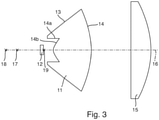
- figure 3 shows a vertical section through the arrangement figure 2 .
- the catadioptric primary optics 11 shown here has a refractive lens part in the center around the optical axis 16 and an outer reflecting part, which surrounds the lens section, with totally reflecting boundary surfaces 13 .
- One The light entrance surface of the reflecting part of the primary optics 11 is denoted by the reference numeral 14a and a light entrance surface of the central lens part of the primary optics 11 by the reference numeral 14b.
- the focal points 17, 18, 19 and their positions relative to one another and with respect to the semiconductor light source 12 can be clearly seen.
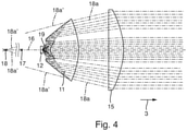
- FIG. 4 the optical system of the light module 10 is off figure 3 10 is shown with exemplary light rays traveling in the vertical plane and originating at the center of the light emitting surface of the semiconductor light source 12.
- the focal point 17 of the primary optics 11 is arranged between the focal point 18 and the semiconductor light source 12.
- the focal point 19 of the entire system is arranged on the light-emitting surface of the light source 12 .
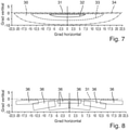
- figure 6 shows a plan view of the light module 10 from FIGS Figures 1 to 4 . It can be clearly seen that there is practically no collimation of the light beams in the horizontal plane due to the secondary optics 15 . With this structure, a resulting light distribution 30 can be generated, as is the case, for example, in figure 7 is shown.
- figure 7 shows a measuring screen arranged at a distance (eg 25 m) in front of the motor vehicle or in front of the light module 10, on which a horizontal axis and a vertical axis are plotted, which intersect at one point.
- the light distribution 30 forms a sharp light-dark boundary 31 just below the 0° line (vertical) and can therefore be used as a low beam distribution or as part of it.
- Examples are lines with the same illuminance (so-called isolux lines) drawn in the light distribution 30 .
- a reference numeral 32 denotes a solid line for 10.0 lx, 33 a broken line for 1.0 lx, and 34 a chain line for 0.1 lx.
- Various criteria can be used to define the light-dark boundary 31 .
- the position of the 0.1 lx iso line 34 was used as a simple criterion.
- figure 8 shows how the light distribution 30 is created by superimposing different images 36 of the light-emitting surface of the light source 12.
- the different segments or facets 13 of the boundary surfaces of the primary optics 11 are designed in such a way that the uppermost corner or edge of the image lies on the line that marks the target position of the light-dark boundary 31 .
- the light source 12 in this example is an LED, the luminous surface of which is square in shape
- all of the images 36 are rectangular in shape with widely differing lengths and widths.
- These images 36 result because the imaging of the system is anamorphic, ie the LED chip image 36 is enlarged differently in the horizontal and vertical directions. In the system described, the horizontal magnification is always greater than the vertical because the vertical focal length of the overall system is longer than the horizontal focal length.
- the second lens 15 is a cylindrical optic, it does not have a focal point, but rather a focal line. As a result, it is easily possible to use a plurality of first optics 11 in order, for example, to increase the luminous flux of the overall system. To do this, the additional optics must be placed on a line that runs parallel to the focal line.
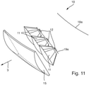
- An example of a realization of such a system shows figure 9 .
- an optical system of a light module 10 is shown comprising three semiconductor light sources 12, three primary optics 11 assigned to them in the form of catadioptric optics, and secondary optics 15 in the form of a cylindrical lens.
- the cylindrical lens includes a focal line 18a.
- the light-emitting surfaces of the LEDs 12 are arranged on a line 19a, which preferably runs parallel to the focal line 18a of the secondary optics 15.
- the line 19a corresponds to a focal line of the entire optical system of the light module 10.
- the secondary optics 15 is designed in the form of a curved cylindrical lens in order to achieve an attractive design of the light exit surface of the light module 10 .
- the cylindrical lens 15 is bent in a horizontal plane.
- the curvature of the lens surface in the vertical section has remained constant.
- the focal length of the cylindrical lens 15 in the vertical section does not change, but the position and shape of the focal line 18a, which is now also bent in the horizontal plane, does.
- first optics 11 and second optics 15 thereby produces different horizontal and vertical magnifications and each first optics 11 must therefore be designed differently.
- the focal line 18a of the secondary optics 15 and the focal line 19a of the entire optical system no longer run parallel to one another.
- each optical subsystem (with elements 12, 11, 15) is intended to generate a comparable light distribution, as is the case, for example, with pixel-shaped light distributions for adaptive high beam distributions (e.g. partial high beam, marking light, etc.).
- each subsystem provides the same magnification of the images of the light-emitting surface of the semiconductor light sources 12 in the horizontal or vertical direction.
- the position of the LEDs 12 must be selected on a line 19a parallel to the focal line 18a of the secondary optics 15.
- a corresponding example is in figure 12 shown.
- a light distribution 30 with a horizontal light-dark boundary 31 (cf. figure 7 ) generated.
- the invention can also be used to generate light distributions with horizontal and/or vertical or arbitrarily shaped and/or aligned light-dark boundaries by positioning the corners of the LED chip images along predetermined lines, with the lines then forming the light-dark boundaries of the light distribution .
- figure 13 shows an example of how the LED chip images 41 of different areas 13 of a first optics 11 can be positioned in order to generate a strip-shaped light distribution 40 with vertical light-dark borders 42 and horizontal light-dark borders 43 .
- FIGS. 14 to 21 show examples of a total of 21 individual light distributions 50, which can each be generated by an LED 12 with associated first optics 11 and the second optics 15 in the form of a cylindrical lens.
- figure 14 shows the individual light distributions 50 of LEDs #1 to #3, figure 15 from LEDs #4 to #6, figure 16 from LEDs #7 to #9, figure 17 of LEDs #10 and #11, figure 18 from LEDs #12 to #14, figure 19 from LEDs #15 to #17, figure 20 from LEDs #18 to #20 and figure 21 from LED #21.
- the individual light distributions 50 each have two vertical light-dark boundaries 51 and two horizontal light-dark boundaries 52 . This illuminates a defined angular range horizontally and vertically. Lines with the same illuminance levels (so-called isolux lines) are drawn in the individual light distributions 50 by way of example.
- a solid line for 50.0 lx is denoted by reference numeral 53, a broken line for 10 lx by 54, and a chain line for 0.1 lx by 55.
- Various criteria can be used to define the light-dark boundaries 51, 52. In the example shown, the position of the 0.1 lx iso line 55 was used as a simple criterion. Based on this definition, the illuminated angular range is approximately 3° wide horizontally and 10° vertically high.
- the in figure 22 shown resulting light distribution 60, which can serve as a high beam distribution.
- Lines with the same illuminance levels are drawn in the light distribution 60 by way of example.
- a solid line for 50.0 lx is denoted by reference numeral 61, a broken line for 10 lx by 62 and a broken line for 0.1 lx by 63. Since the individual light distributions 50 are each offset horizontally by approx. 1.5° from one another, 12 angle areas with a minimum width of approx. 1.5° can be switched dark by deactivating or dimming individual LEDs.
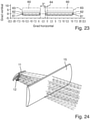
- An example of an overall light distribution 60 with two times 1.5° wide dark blanking area 64 is shown figure 23 .
- the motor vehicle in which headlights 1 with the light module 10 according to the invention are installed has suitable means for detecting other road users in front of the motor vehicle. These means include, for example, a video camera for recording images of the area in front of the motor vehicle and a computing unit for evaluating the recorded images and for detecting oncoming vehicles or vehicles driving ahead in a specific area of the images.
- the area of the high beam distribution 60 off figure 22 is specifically darkened or hidden by deactivating or dimming certain LEDs 12 in order to prevent road users from being dazzled.
- the high beam can remain switched on in all other areas of light distribution 60 in order to ensure good visibility for the driver of the motor vehicle.
- the blanking area 64 can change dynamically, for example when another oncoming road user drives past the motor vehicle with the light module 10 or when a preceding road user is driving in front of the motor vehicle on a winding road.
- the width of the blanking area 64 can be individually adapted to the current traffic situation.
- the LEDs 12 are typically energized in a pulse width modulated manner.
- the luminous flux can be controlled by changing the pulse width.
- the first optics 11 is implemented as a reflector and the second optics 15 as a cylindrical lens.
- the second optics 15 it is advantageous to implement it with a plurality of LEDs 12, associated reflectors 11 and a cylindrical lens 15, as in figure 25 shown.
- a low beam distribution 80 with an asymmetrical (bent) light-dark boundary 81 can be generated from this, for example, as is shown, for example, in figure 30 is shown.
- the Figures 26 to 29 show individual light distributions 70 which are generated by subsystems #1 to #5, each comprising an LED 12, a reflector 11 and the cylindrical lens 15.
- Subsystems #1 to #3 produce, for example, light distributions 70 with a horizontal light-dark boundary 71 that is just below 0° vertically (cf. Figures 26 to 28 ). Lines with the same illuminance levels (so-called isolux lines) are drawn in the individual light distributions 70 by way of example.
- a solid line for 4.0 lx is denoted by 72, a broken line for 0.4 lx by 73 and a dashed line for 0.1 lx denoted by 74.
- Various criteria can be used to define the light-dark boundary 71 .
- the position of the 0.1 lx iso line 74 was used as a simple criterion.
- FIG 26 is the individual light distribution 70 generated by subsystem #1, in figure 27 those through subsystem #2 and in figure 28 the individual light distribution 70 produced by subsystem #3 is shown.
- figure 29 1 shows an individual light distribution 70 as produced by subsystem #4 (LED #4, reflector #4 and cylindrical lens 15) and subsystem #5 (LED #5, reflector #5 and cylindrical lens 15) of light module 10, respectively figure 25 is produced.
- the light distribution 70 has a light-dark boundary 71a that rises obliquely from the center (point of intersection of the horizontal and the vertical) to the top right (towards one's own traffic side).
- the illuminance distribution in the light distributions 70 is illustrated by iso-lines.
- a solid line for 4.0 lx is denoted by reference numeral 72, a broken line for 1.0 lx by 73a, and a chain line for 0.1 lx by 74.
- FIG. Of course, these values for the illuminance are only selected as examples and in practice they can deviate from the values given here.
- figure 30 shows the resulting total light distribution 80 of the light module 10 in the form of a low beam distribution with an asymmetrical light-dark boundary 81.
- the light distribution 80 results from a superimposition of the individual light distributions 70 of the LEDs #1 to #5 from FIGS Figures 26 to 29 .
- the light-dark boundary 81 of the light distribution 80 has an incline approximately from the center (point of intersection of the horizontal and the vertical) to the top right (towards one's own traffic side). rising section 81a.
- the illuminance distribution in the light distributions 80 is illustrated by iso-lines.
- a reference numeral 82 is a solid line for 10.0 lx
- 83a is a broken line for 1.0 lx
- 84 is a chain line for 0.1 lx.
- a further variant is that a plurality of LEDs 12 each use a first optics 11 .
- the number of generated light areas ("pixels") of an adaptive high beam distribution can be increased without the number of first optics 11 having to be increased.
Landscapes
- Engineering & Computer Science (AREA)
- General Engineering & Computer Science (AREA)
- Physics & Mathematics (AREA)
- Microelectronics & Electronic Packaging (AREA)
- Optics & Photonics (AREA)
- Non-Portable Lighting Devices Or Systems Thereof (AREA)
Claims (13)
- Module de lumière (10) pour un phare de véhicule automobile (1), comprenant:- au moins une source de lumière à semi-conducteur (12) comprenant une surface émettrice de lumière pour émettre de la lumière,- au moins une optique primaire (11) destinée à concentrer au moins une partie de la lumière émise, dans lequel ladite optique primaire (11) présente un foyer (17) qui, vu à l'encontre d'une direction de sortie de lumière (3), est disposé derrière ladite au moins une source de lumière à semi-conducteur (12),- une optique secondaire (15) destinée à concentrer encore plus la lumière déjà concentrée par ladite au moins une optique primaire (11) et à générer une répartition de lumière résultante (30; 40; 60; 80) du module de lumière (10) sur une chaussée située devant le véhicule automobile, dans lequel l'optique secondaire (15) présente un foyer (18) ou une ligne focale (18a) qui, vu(e) à l'encontre d'une direction de sortie de lumière (3), est disposé(e) derrière ladite au moins une source de lumière à semi-conducteur (12), et dans lequel- l'ensemble du système optique du module de lumière (10) qui comprend ladite au moins une optique primaire (11) et ladite optique secondaire (15), présente un foyer (19) ou une ligne focale (19a) qui est disposé(e) au niveau de la surface émettrice de lumière de ladite au moins une source de lumière à semi-conducteur (12),caractérisé par le fait que l'optique primaire (11) est conçue comme une optique catadioptrique qui présente une épaisseur centrale maximale inférieure à 20 mm et qui présente des zones (13) de forme différente sous la forme de segments ou de facettes réfléchissant(e)s, dans lequel chacune de ces zones (13) réfléchit de la lumière de ladite au moins une source de lumière à semi-conducteur (12) pour générer une zone partielle (36; 41; 50; 70) de la répartition de lumière (30; 40; 60; 80), et la répartition de lumière résultante (30; 40; 60; 80) du module de lumière résulte par une superposition des zones partielles (36; 41; 50; 70) de la répartition de lumière (30; 40; 60; 80) par les différentes zones (13) de l'optique primaire (11), dans lequel l'optique secondaire présente une épaisseur centrale maximale inférieure à 20 mm et forme la surface de sortie de lumière du système optique du module de lumière et, contrairement à l'optique primaire, ne présente pas de zones différentes visibles pour la mise en forme de la lumière, et dans lequel toutes les optiques sont des optiques astigmates qui présentent des distances focales clairement différentes dans un plan vertical et un plan horizontal.
- Module de lumière (10) selon la revendication 1, caractérisé par le fait que ladite au moins une optique primaire (11) est conçue en tant qu'optique auxiliaire en un matériau transparent qui présente au moins une surface d'entrée de lumière, une pluralité d'interfaces totalement réfléchissantes et au moins une surface de sortie de lumière (14) et qui concentre la lumière provenant de ladite au moins une source de lumière à semi-conducteur (12) par réfraction en entrant dans l'optique auxiliaire et/ou en sortant de l'optique auxiliaire et par réflexion interne totale aux interfaces.
- Module de lumière (10) selon la revendication 2, caractérisé par le fait qu'au moins l'une des surfaces de sortie de lumière (14) de ladite au moins une optique primaire (11) présente une modulation en forme d'onde ou de coussin.
- Module de lumière (10) selon la revendication 1 ou 2, caractérisé par le fait que l'optique secondaire (15) est conçue de telle sorte qu'elle concentre plus fortement la lumière passante dans un premier plan qui comprend un axe optique (16) du système optique du module de lumière (10) que dans un deuxième plan qui comprend l'axe optique (16) du système optique du module de lumière (10) et qui s'étend perpendiculairement au premier plan.
- Module de lumière (10) selon la revendication 4, caractérisé par le fait que l'optique secondaire (15) présente une étendue nettement plus faible dans le premier plan que dans le deuxième plan.
- Module de lumière (10) selon la revendication 5, caractérisé par le fait que l'optique secondaire (15) est conçue sous la forme d'une lentille cylindrique dont l'axe cylindrique (18a) s'étend dans le deuxième plan ou parallèlement à celui-ci.
- Module de lumière (10) selon la revendication 1 ou 2, caractérisé par le fait que la répartition de lumière résultante (30; 40; 60; 80) du module de lumière (10), après avoir traversé l'optique secondaire (15), résulte par une superposition des zones partielles (36; 41; 50; 70) de la répartition de lumière (30; 40; 60; 80) par les différentes zones (13) de l'optique primaire (11).
- Module de lumière (10) selon l'une quelconque des revendications 1 à 7, caractérisé par le fait que ladite au moins une optique primaire (11) et ladite optique secondaire (15) sont coordonnées en termes d'agencement et de conception de telle sorte que la répartition de lumière résultante du module de lumière (10) est une répartition de lumière passée en code (30) sous la forme d'une répartition de feux de croisement ou de feux de brouillard avec une limite claire-obscure horizontale (31) ou une répartition de lumière en forme de bande (40) avec des limites claires-obscures verticales et horizontales (41, 42) ou une répartition partielle de phare à longue portée (60; 80) avec des limites claires-obscures verticales et horizontales.
- Module de lumière (10) selon l'une quelconque des revendications 1 à 8, caractérisé par le fait que le module de lumière (10) comprend une pluralité de sources de lumière à semi-conducteur (12) dont les surfaces émettrices de lumière sont disposées sur une ligne (19a) ou bien dans un plan.
- Module de lumière (10) selon la revendication 9, caractérisé par le fait que la ligne (19a) ou bien le plan sur laquelle/lequel sont disposées les surfaces émettrices de lumière des sources de lumière à semi-conducteur (12) s'étend parallèlement à une ligne focale (18a) de l'optique secondaire (15).
- Module de lumière (10) selon la revendication 9, caractérisé par le fait que la ligne (19a) ou bien le plan sur laquelle/lequel sont disposées les surfaces émettrices de lumière des sources de lumière à semi-conducteur (12) est courbé(e).
- Module de lumière (10) selon l'une quelconque des revendications 9 à 11, caractérisé par le fait que le module de lumière (10) comprend une pluralité de sources de lumière à semi-conducteur (12) qui peuvent être individuellement allumées et éteintes et dont on peut faire varier individuellement l'intensité de lumière.
- Module de lumière (10) selon l'une quelconque des revendications 9 à 12, caractérisé par le fait qu'au moins deux des sources de lumière à semi-conducteur (12) émettent de la lumière pour générer des répartitions de lumière différentes, et que, pour commuter entre les répartitions de lumière, les sources de lumière à semi-conducteur (12) sont allumées ou éteintes ou variées en intensité de lumière de manière visée.
Applications Claiming Priority (1)
| Application Number | Priority Date | Filing Date | Title |
|---|---|---|---|
| DE102016118152.8A DE102016118152A1 (de) | 2016-09-26 | 2016-09-26 | Lichtmodul für einen Kraftfahrzeugscheinwerfer |
Publications (2)
| Publication Number | Publication Date |
|---|---|
| EP3301350A1 EP3301350A1 (fr) | 2018-04-04 |
| EP3301350B1 true EP3301350B1 (fr) | 2022-02-23 |
Family
ID=59829256
Family Applications (1)
| Application Number | Title | Priority Date | Filing Date |
|---|---|---|---|
| EP17190034.3A Active EP3301350B1 (fr) | 2016-09-26 | 2017-09-08 | Module d'éclairage pour phare de véhicule automobile |
Country Status (2)
| Country | Link |
|---|---|
| EP (1) | EP3301350B1 (fr) |
| DE (1) | DE102016118152A1 (fr) |
Families Citing this family (5)
| Publication number | Priority date | Publication date | Assignee | Title |
|---|---|---|---|---|
| EP3550203B1 (fr) * | 2018-04-04 | 2022-12-21 | ZKW Group GmbH | Module d'éclairage pour un dispositif d'éclairage de véhicule automobile en flèche |
| FR3084728B1 (fr) * | 2018-07-31 | 2021-03-19 | Valeo Vision | Module lumineux imageant la surface eclairee d'un collecteur |
| CN212746315U (zh) * | 2020-07-02 | 2021-03-19 | 华域视觉科技(上海)有限公司 | 透镜单元、辅助近光模组、透镜、近光照明模组和车辆 |
| DE102021124722A1 (de) | 2021-09-24 | 2023-03-30 | Bartenbach Holding Gmbh | Strahler |
| CN116221647B (zh) * | 2023-05-08 | 2023-07-28 | 常州星宇车灯股份有限公司 | 车灯远光照明系统、照明模组及车辆 |
Family Cites Families (9)
| Publication number | Priority date | Publication date | Assignee | Title |
|---|---|---|---|---|
| FR2772111B1 (fr) * | 1997-12-05 | 2000-02-25 | Valeo Vision | Projecteur a reflecteur hyperbolique et bloc optique comportant un tel projecteur |
| JP4391870B2 (ja) | 2004-04-02 | 2009-12-24 | 株式会社小糸製作所 | 車両用照明灯具 |
| JP4752626B2 (ja) * | 2006-06-01 | 2011-08-17 | 市光工業株式会社 | 車両用灯具 |
| DE102008027320A1 (de) | 2008-06-07 | 2009-12-10 | Hella Kgaa Hueck & Co. | Scheinwerfer für Fahrzeuge |
| DE102011078653B4 (de) | 2011-07-05 | 2013-12-12 | Automotive Lighting Reutlingen Gmbh | Vorsatzoptik zur Bündelung von ausgesandtem Licht mindestens einer Halbleiterlichtquelle |
| AT512711B1 (de) * | 2012-03-21 | 2014-08-15 | Zizala Lichtsysteme Gmbh | Lichtmodul für ein Kraftfahrzeug und Kraftfahrzeugscheinwerfer |
| DE102012211613A1 (de) * | 2012-07-04 | 2014-01-09 | Automotive Lighting Reutlingen Gmbh | Lichtmodul |
| US8733992B2 (en) | 2012-10-01 | 2014-05-27 | Osram Sylvania, Inc. | LED low profile linear front fog module |
| DE102014203335A1 (de) * | 2014-02-25 | 2015-08-27 | Automotive Lighting Reutlingen Gmbh | Lichtmodul eines Kraftfahrzeugscheinwerfers und Scheinwerfer mit einem solchen Lichtmodul |
-
2016
- 2016-09-26 DE DE102016118152.8A patent/DE102016118152A1/de not_active Withdrawn
-
2017
- 2017-09-08 EP EP17190034.3A patent/EP3301350B1/fr active Active
Also Published As
| Publication number | Publication date |
|---|---|
| EP3301350A1 (fr) | 2018-04-04 |
| DE102016118152A1 (de) | 2018-03-29 |
Similar Documents
| Publication | Publication Date | Title |
|---|---|---|
| EP2910847B1 (fr) | Module d'éclairage d'un projecteur de véhicule automobile et projecteur avec un tel module d'éclairage | |
| EP3301350B1 (fr) | Module d'éclairage pour phare de véhicule automobile | |
| EP2799762B1 (fr) | Module d'éclairage de phare de véhicule automobile | |
| EP2893249B1 (fr) | Unité d'éclairage destinée à un projecteur | |
| DE112013007443B4 (de) | Scheinwerfer zur Verwendung in einem Fahrzeug | |
| EP2789901B1 (fr) | Module d'éclairage pour un dispositif d'éclairage de véhicule automobile | |
| EP2799761B1 (fr) | Module d'éclairage de phare de véhicule automobile | |
| EP2587125B1 (fr) | Module de projection de phare pour un véhicule automobile | |
| EP3714205B1 (fr) | Module d'éclairage pour phare de véhicule automobile | |
| DE102011078653B4 (de) | Vorsatzoptik zur Bündelung von ausgesandtem Licht mindestens einer Halbleiterlichtquelle | |
| EP2505910B1 (fr) | Phare de véhicule automobile équipé d'une source lumineuse semi-conductrice | |
| DE102014200368B4 (de) | Teilfernlicht-Projektionslichtmodul für einen Kraftfahrzeugscheinwerfer | |
| EP2846077A2 (fr) | Optique de projection destinée à être utilisée dans un module à DEL d'un phare de véhicule automobile, et module à DEL et phare de véhicule automobile doté d'une telle optique de projection | |
| DE102013205487A1 (de) | Kraftfahrzeugleuchte für dynamische Leuchtenfunktionen | |
| EP2863108B1 (fr) | Module à LED d'un phare de véhicule automobile | |
| DE102016103288A1 (de) | Leuchtenmodul insbesondere für Straßenleuchten | |
| DE102008036845B4 (de) | Beleuchtungsvorrichtung | |
| EP3765781B1 (fr) | Module de lumière pour phare de véhicule automobile | |
| EP2963334B1 (fr) | Système de conducteurs lumineux utilisé dans un dispositif d'éclairage d'un véhicule automobile et dispositif d'éclairage de véhicule automobile doté d'un tel système de conducteurs lumineux | |
| DE102004032095A1 (de) | Scheinwerfer für Fahrzeuge | |
| DE602004002016T2 (de) | Kfz-Scheinwerfer, der erhöht angeordnete Verkehrszeichen beleuchten kann | |
| EP3719391B1 (fr) | Module de feu de route partiel pour un phare de véhicule automobile | |
| EP3870894B1 (fr) | Unité d'éclairage pour un phare de véhicule automobile | |
| DE2033443A1 (de) | Beleuchtungsvorrichtung, insbeson dere fur Kraftfahrzeuge | |
| DE10310263A1 (de) | LED-Scheinwerfer zur asymmetrischen Ausleuchtung |
Legal Events
| Date | Code | Title | Description |
|---|---|---|---|
| PUAI | Public reference made under article 153(3) epc to a published international application that has entered the european phase |
Free format text: ORIGINAL CODE: 0009012 |
|
| STAA | Information on the status of an ep patent application or granted ep patent |
Free format text: STATUS: THE APPLICATION HAS BEEN PUBLISHED |
|
| AK | Designated contracting states |
Kind code of ref document: A1 Designated state(s): AL AT BE BG CH CY CZ DE DK EE ES FI FR GB GR HR HU IE IS IT LI LT LU LV MC MK MT NL NO PL PT RO RS SE SI SK SM TR |
|
| AX | Request for extension of the european patent |
Extension state: BA ME |
|
| STAA | Information on the status of an ep patent application or granted ep patent |
Free format text: STATUS: REQUEST FOR EXAMINATION WAS MADE |
|
| 17P | Request for examination filed |
Effective date: 20181004 |
|
| RBV | Designated contracting states (corrected) |
Designated state(s): AL AT BE BG CH CY CZ DE DK EE ES FI FR GB GR HR HU IE IS IT LI LT LU LV MC MK MT NL NO PL PT RO RS SE SI SK SM TR |
|
| STAA | Information on the status of an ep patent application or granted ep patent |
Free format text: STATUS: REQUEST FOR EXAMINATION WAS MADE |
|
| RIC1 | Information provided on ipc code assigned before grant |
Ipc: F21S 41/26 20180101AFI20210720BHEP Ipc: F21S 41/265 20180101ALI20210720BHEP Ipc: F21S 41/143 20180101ALI20210720BHEP Ipc: F21S 41/148 20180101ALI20210720BHEP Ipc: F21S 41/33 20180101ALI20210720BHEP Ipc: F21V 5/00 20180101ALI20210720BHEP |
|
| GRAP | Despatch of communication of intention to grant a patent |
Free format text: ORIGINAL CODE: EPIDOSNIGR1 |
|
| STAA | Information on the status of an ep patent application or granted ep patent |
Free format text: STATUS: GRANT OF PATENT IS INTENDED |
|
| INTG | Intention to grant announced |
Effective date: 20210914 |
|
| GRAS | Grant fee paid |
Free format text: ORIGINAL CODE: EPIDOSNIGR3 |
|
| GRAA | (expected) grant |
Free format text: ORIGINAL CODE: 0009210 |
|
| STAA | Information on the status of an ep patent application or granted ep patent |
Free format text: STATUS: THE PATENT HAS BEEN GRANTED |
|
| AK | Designated contracting states |
Kind code of ref document: B1 Designated state(s): AL AT BE BG CH CY CZ DE DK EE ES FI FR GB GR HR HU IE IS IT LI LT LU LV MC MK MT NL NO PL PT RO RS SE SI SK SM TR |
|
| REG | Reference to a national code |
Ref country code: GB Ref legal event code: FG4D Free format text: NOT ENGLISH |
|
| REG | Reference to a national code |
Ref country code: CH Ref legal event code: EP |
|
| REG | Reference to a national code |
Ref country code: DE Ref legal event code: R096 Ref document number: 502017012630 Country of ref document: DE |
|
| REG | Reference to a national code |
Ref country code: AT Ref legal event code: REF Ref document number: 1470735 Country of ref document: AT Kind code of ref document: T Effective date: 20220315 |
|
| REG | Reference to a national code |
Ref country code: IE Ref legal event code: FG4D Free format text: LANGUAGE OF EP DOCUMENT: GERMAN |
|
| REG | Reference to a national code |
Ref country code: LT Ref legal event code: MG9D |
|
| REG | Reference to a national code |
Ref country code: NL Ref legal event code: MP Effective date: 20220223 |
|
| PG25 | Lapsed in a contracting state [announced via postgrant information from national office to epo] |
Ref country code: SE Free format text: LAPSE BECAUSE OF FAILURE TO SUBMIT A TRANSLATION OF THE DESCRIPTION OR TO PAY THE FEE WITHIN THE PRESCRIBED TIME-LIMIT Effective date: 20220223 Ref country code: RS Free format text: LAPSE BECAUSE OF FAILURE TO SUBMIT A TRANSLATION OF THE DESCRIPTION OR TO PAY THE FEE WITHIN THE PRESCRIBED TIME-LIMIT Effective date: 20220223 Ref country code: PT Free format text: LAPSE BECAUSE OF FAILURE TO SUBMIT A TRANSLATION OF THE DESCRIPTION OR TO PAY THE FEE WITHIN THE PRESCRIBED TIME-LIMIT Effective date: 20220623 Ref country code: NO Free format text: LAPSE BECAUSE OF FAILURE TO SUBMIT A TRANSLATION OF THE DESCRIPTION OR TO PAY THE FEE WITHIN THE PRESCRIBED TIME-LIMIT Effective date: 20220523 Ref country code: NL Free format text: LAPSE BECAUSE OF FAILURE TO SUBMIT A TRANSLATION OF THE DESCRIPTION OR TO PAY THE FEE WITHIN THE PRESCRIBED TIME-LIMIT Effective date: 20220223 Ref country code: LT Free format text: LAPSE BECAUSE OF FAILURE TO SUBMIT A TRANSLATION OF THE DESCRIPTION OR TO PAY THE FEE WITHIN THE PRESCRIBED TIME-LIMIT Effective date: 20220223 Ref country code: HR Free format text: LAPSE BECAUSE OF FAILURE TO SUBMIT A TRANSLATION OF THE DESCRIPTION OR TO PAY THE FEE WITHIN THE PRESCRIBED TIME-LIMIT Effective date: 20220223 Ref country code: ES Free format text: LAPSE BECAUSE OF FAILURE TO SUBMIT A TRANSLATION OF THE DESCRIPTION OR TO PAY THE FEE WITHIN THE PRESCRIBED TIME-LIMIT Effective date: 20220223 Ref country code: BG Free format text: LAPSE BECAUSE OF FAILURE TO SUBMIT A TRANSLATION OF THE DESCRIPTION OR TO PAY THE FEE WITHIN THE PRESCRIBED TIME-LIMIT Effective date: 20220523 |
|
| PG25 | Lapsed in a contracting state [announced via postgrant information from national office to epo] |
Ref country code: PL Free format text: LAPSE BECAUSE OF FAILURE TO SUBMIT A TRANSLATION OF THE DESCRIPTION OR TO PAY THE FEE WITHIN THE PRESCRIBED TIME-LIMIT Effective date: 20220223 Ref country code: LV Free format text: LAPSE BECAUSE OF FAILURE TO SUBMIT A TRANSLATION OF THE DESCRIPTION OR TO PAY THE FEE WITHIN THE PRESCRIBED TIME-LIMIT Effective date: 20220223 Ref country code: GR Free format text: LAPSE BECAUSE OF FAILURE TO SUBMIT A TRANSLATION OF THE DESCRIPTION OR TO PAY THE FEE WITHIN THE PRESCRIBED TIME-LIMIT Effective date: 20220524 Ref country code: FI Free format text: LAPSE BECAUSE OF FAILURE TO SUBMIT A TRANSLATION OF THE DESCRIPTION OR TO PAY THE FEE WITHIN THE PRESCRIBED TIME-LIMIT Effective date: 20220223 |
|
| PG25 | Lapsed in a contracting state [announced via postgrant information from national office to epo] |
Ref country code: IS Free format text: LAPSE BECAUSE OF FAILURE TO SUBMIT A TRANSLATION OF THE DESCRIPTION OR TO PAY THE FEE WITHIN THE PRESCRIBED TIME-LIMIT Effective date: 20220623 |
|
| PG25 | Lapsed in a contracting state [announced via postgrant information from national office to epo] |
Ref country code: SM Free format text: LAPSE BECAUSE OF FAILURE TO SUBMIT A TRANSLATION OF THE DESCRIPTION OR TO PAY THE FEE WITHIN THE PRESCRIBED TIME-LIMIT Effective date: 20220223 Ref country code: SK Free format text: LAPSE BECAUSE OF FAILURE TO SUBMIT A TRANSLATION OF THE DESCRIPTION OR TO PAY THE FEE WITHIN THE PRESCRIBED TIME-LIMIT Effective date: 20220223 Ref country code: RO Free format text: LAPSE BECAUSE OF FAILURE TO SUBMIT A TRANSLATION OF THE DESCRIPTION OR TO PAY THE FEE WITHIN THE PRESCRIBED TIME-LIMIT Effective date: 20220223 Ref country code: EE Free format text: LAPSE BECAUSE OF FAILURE TO SUBMIT A TRANSLATION OF THE DESCRIPTION OR TO PAY THE FEE WITHIN THE PRESCRIBED TIME-LIMIT Effective date: 20220223 Ref country code: DK Free format text: LAPSE BECAUSE OF FAILURE TO SUBMIT A TRANSLATION OF THE DESCRIPTION OR TO PAY THE FEE WITHIN THE PRESCRIBED TIME-LIMIT Effective date: 20220223 Ref country code: CZ Free format text: LAPSE BECAUSE OF FAILURE TO SUBMIT A TRANSLATION OF THE DESCRIPTION OR TO PAY THE FEE WITHIN THE PRESCRIBED TIME-LIMIT Effective date: 20220223 |
|
| REG | Reference to a national code |
Ref country code: DE Ref legal event code: R097 Ref document number: 502017012630 Country of ref document: DE |
|
| PG25 | Lapsed in a contracting state [announced via postgrant information from national office to epo] |
Ref country code: AL Free format text: LAPSE BECAUSE OF FAILURE TO SUBMIT A TRANSLATION OF THE DESCRIPTION OR TO PAY THE FEE WITHIN THE PRESCRIBED TIME-LIMIT Effective date: 20220223 |
|
| PLBE | No opposition filed within time limit |
Free format text: ORIGINAL CODE: 0009261 |
|
| STAA | Information on the status of an ep patent application or granted ep patent |
Free format text: STATUS: NO OPPOSITION FILED WITHIN TIME LIMIT |
|
| 26N | No opposition filed |
Effective date: 20221124 |
|
| PG25 | Lapsed in a contracting state [announced via postgrant information from national office to epo] |
Ref country code: SI Free format text: LAPSE BECAUSE OF FAILURE TO SUBMIT A TRANSLATION OF THE DESCRIPTION OR TO PAY THE FEE WITHIN THE PRESCRIBED TIME-LIMIT Effective date: 20220223 |
|
| PG25 | Lapsed in a contracting state [announced via postgrant information from national office to epo] |
Ref country code: MC Free format text: LAPSE BECAUSE OF FAILURE TO SUBMIT A TRANSLATION OF THE DESCRIPTION OR TO PAY THE FEE WITHIN THE PRESCRIBED TIME-LIMIT Effective date: 20220223 |
|
| REG | Reference to a national code |
Ref country code: CH Ref legal event code: PL |
|
| GBPC | Gb: european patent ceased through non-payment of renewal fee |
Effective date: 20220908 |
|
| REG | Reference to a national code |
Ref country code: BE Ref legal event code: MM Effective date: 20220930 |
|
| PG25 | Lapsed in a contracting state [announced via postgrant information from national office to epo] |
Ref country code: LU Free format text: LAPSE BECAUSE OF NON-PAYMENT OF DUE FEES Effective date: 20220908 |
|
| PG25 | Lapsed in a contracting state [announced via postgrant information from national office to epo] |
Ref country code: LI Free format text: LAPSE BECAUSE OF NON-PAYMENT OF DUE FEES Effective date: 20220930 Ref country code: IT Free format text: LAPSE BECAUSE OF FAILURE TO SUBMIT A TRANSLATION OF THE DESCRIPTION OR TO PAY THE FEE WITHIN THE PRESCRIBED TIME-LIMIT Effective date: 20220223 Ref country code: IE Free format text: LAPSE BECAUSE OF NON-PAYMENT OF DUE FEES Effective date: 20220908 Ref country code: FR Free format text: LAPSE BECAUSE OF NON-PAYMENT OF DUE FEES Effective date: 20220930 Ref country code: CH Free format text: LAPSE BECAUSE OF NON-PAYMENT OF DUE FEES Effective date: 20220930 |
|
| PG25 | Lapsed in a contracting state [announced via postgrant information from national office to epo] |
Ref country code: BE Free format text: LAPSE BECAUSE OF NON-PAYMENT OF DUE FEES Effective date: 20220930 |
|
| PG25 | Lapsed in a contracting state [announced via postgrant information from national office to epo] |
Ref country code: GB Free format text: LAPSE BECAUSE OF NON-PAYMENT OF DUE FEES Effective date: 20220908 |
|
| REG | Reference to a national code |
Ref country code: AT Ref legal event code: MM01 Ref document number: 1470735 Country of ref document: AT Kind code of ref document: T Effective date: 20220908 |
|
| PGFP | Annual fee paid to national office [announced via postgrant information from national office to epo] |
Ref country code: DE Payment date: 20230822 Year of fee payment: 7 |
|
| PG25 | Lapsed in a contracting state [announced via postgrant information from national office to epo] |
Ref country code: AT Free format text: LAPSE BECAUSE OF NON-PAYMENT OF DUE FEES Effective date: 20220908 |
|
| PG25 | Lapsed in a contracting state [announced via postgrant information from national office to epo] |
Ref country code: HU Free format text: LAPSE BECAUSE OF FAILURE TO SUBMIT A TRANSLATION OF THE DESCRIPTION OR TO PAY THE FEE WITHIN THE PRESCRIBED TIME-LIMIT; INVALID AB INITIO Effective date: 20170908 |