EP2799588A2 - Architekturen für Hochtemperatur-TBCs mit ultraniedriger Wärmeleitfähigkeit und Zerreibbarkeit sowie Verfahren zur Herstellung - Google Patents
Architekturen für Hochtemperatur-TBCs mit ultraniedriger Wärmeleitfähigkeit und Zerreibbarkeit sowie Verfahren zur Herstellung Download PDFInfo
- Publication number
- EP2799588A2 EP2799588A2 EP14163745.4A EP14163745A EP2799588A2 EP 2799588 A2 EP2799588 A2 EP 2799588A2 EP 14163745 A EP14163745 A EP 14163745A EP 2799588 A2 EP2799588 A2 EP 2799588A2
- Authority
- EP
- European Patent Office
- Prior art keywords
- thermal barrier
- barrier coating
- particles
- coatings
- thermal
- Prior art date
- Legal status (The legal status is an assumption and is not a legal conclusion. Google has not performed a legal analysis and makes no representation as to the accuracy of the status listed.)
- Granted
Links
Images


Classifications
-
- F—MECHANICAL ENGINEERING; LIGHTING; HEATING; WEAPONS; BLASTING
- F01—MACHINES OR ENGINES IN GENERAL; ENGINE PLANTS IN GENERAL; STEAM ENGINES
- F01D—NON-POSITIVE DISPLACEMENT MACHINES OR ENGINES, e.g. STEAM TURBINES
- F01D25/00—Component parts, details, or accessories, not provided for in, or of interest apart from, other groups
- F01D25/005—Selecting particular materials
-
- C—CHEMISTRY; METALLURGY
- C04—CEMENTS; CONCRETE; ARTIFICIAL STONE; CERAMICS; REFRACTORIES
- C04B—LIME, MAGNESIA; SLAG; CEMENTS; COMPOSITIONS THEREOF, e.g. MORTARS, CONCRETE OR LIKE BUILDING MATERIALS; ARTIFICIAL STONE; CERAMICS; REFRACTORIES; TREATMENT OF NATURAL STONE
- C04B35/00—Shaped ceramic products characterised by their composition; Ceramics compositions; Processing powders of inorganic compounds preparatory to the manufacturing of ceramic products
- C04B35/01—Shaped ceramic products characterised by their composition; Ceramics compositions; Processing powders of inorganic compounds preparatory to the manufacturing of ceramic products based on oxide ceramics
- C04B35/48—Shaped ceramic products characterised by their composition; Ceramics compositions; Processing powders of inorganic compounds preparatory to the manufacturing of ceramic products based on oxide ceramics based on zirconium or hafnium oxides, zirconates, zircon or hafnates
- C04B35/486—Fine ceramics
-
- C—CHEMISTRY; METALLURGY
- C04—CEMENTS; CONCRETE; ARTIFICIAL STONE; CERAMICS; REFRACTORIES
- C04B—LIME, MAGNESIA; SLAG; CEMENTS; COMPOSITIONS THEREOF, e.g. MORTARS, CONCRETE OR LIKE BUILDING MATERIALS; ARTIFICIAL STONE; CERAMICS; REFRACTORIES; TREATMENT OF NATURAL STONE
- C04B35/00—Shaped ceramic products characterised by their composition; Ceramics compositions; Processing powders of inorganic compounds preparatory to the manufacturing of ceramic products
- C04B35/50—Shaped ceramic products characterised by their composition; Ceramics compositions; Processing powders of inorganic compounds preparatory to the manufacturing of ceramic products based on rare-earth compounds
-
- C—CHEMISTRY; METALLURGY
- C23—COATING METALLIC MATERIAL; COATING MATERIAL WITH METALLIC MATERIAL; CHEMICAL SURFACE TREATMENT; DIFFUSION TREATMENT OF METALLIC MATERIAL; COATING BY VACUUM EVAPORATION, BY SPUTTERING, BY ION IMPLANTATION OR BY CHEMICAL VAPOUR DEPOSITION, IN GENERAL; INHIBITING CORROSION OF METALLIC MATERIAL OR INCRUSTATION IN GENERAL
- C23C—COATING METALLIC MATERIAL; COATING MATERIAL WITH METALLIC MATERIAL; SURFACE TREATMENT OF METALLIC MATERIAL BY DIFFUSION INTO THE SURFACE, BY CHEMICAL CONVERSION OR SUBSTITUTION; COATING BY VACUUM EVAPORATION, BY SPUTTERING, BY ION IMPLANTATION OR BY CHEMICAL VAPOUR DEPOSITION, IN GENERAL
- C23C28/00—Coating for obtaining at least two superposed coatings either by methods not provided for in a single one of groups C23C2/00 - C23C26/00 or by combinations of methods provided for in subclasses C23C and C25C or C25D
- C23C28/30—Coatings combining at least one metallic layer and at least one inorganic non-metallic layer
- C23C28/32—Coatings combining at least one metallic layer and at least one inorganic non-metallic layer including at least one pure metallic layer
- C23C28/321—Coatings combining at least one metallic layer and at least one inorganic non-metallic layer including at least one pure metallic layer with at least one metal alloy layer
- C23C28/3215—Coatings combining at least one metallic layer and at least one inorganic non-metallic layer including at least one pure metallic layer with at least one metal alloy layer at least one MCrAlX layer
-
- C—CHEMISTRY; METALLURGY
- C23—COATING METALLIC MATERIAL; COATING MATERIAL WITH METALLIC MATERIAL; CHEMICAL SURFACE TREATMENT; DIFFUSION TREATMENT OF METALLIC MATERIAL; COATING BY VACUUM EVAPORATION, BY SPUTTERING, BY ION IMPLANTATION OR BY CHEMICAL VAPOUR DEPOSITION, IN GENERAL; INHIBITING CORROSION OF METALLIC MATERIAL OR INCRUSTATION IN GENERAL
- C23C—COATING METALLIC MATERIAL; COATING MATERIAL WITH METALLIC MATERIAL; SURFACE TREATMENT OF METALLIC MATERIAL BY DIFFUSION INTO THE SURFACE, BY CHEMICAL CONVERSION OR SUBSTITUTION; COATING BY VACUUM EVAPORATION, BY SPUTTERING, BY ION IMPLANTATION OR BY CHEMICAL VAPOUR DEPOSITION, IN GENERAL
- C23C28/00—Coating for obtaining at least two superposed coatings either by methods not provided for in a single one of groups C23C2/00 - C23C26/00 or by combinations of methods provided for in subclasses C23C and C25C or C25D
- C23C28/30—Coatings combining at least one metallic layer and at least one inorganic non-metallic layer
- C23C28/34—Coatings combining at least one metallic layer and at least one inorganic non-metallic layer including at least one inorganic non-metallic material layer, e.g. metal carbide, nitride, boride, silicide layer and their mixtures, enamels, phosphates and sulphates
- C23C28/345—Coatings combining at least one metallic layer and at least one inorganic non-metallic layer including at least one inorganic non-metallic material layer, e.g. metal carbide, nitride, boride, silicide layer and their mixtures, enamels, phosphates and sulphates with at least one oxide layer
- C23C28/3455—Coatings combining at least one metallic layer and at least one inorganic non-metallic layer including at least one inorganic non-metallic material layer, e.g. metal carbide, nitride, boride, silicide layer and their mixtures, enamels, phosphates and sulphates with at least one oxide layer with a refractory ceramic layer, e.g. refractory metal oxide, ZrO2, rare earth oxides or a thermal barrier system comprising at least one refractory oxide layer
-
- C—CHEMISTRY; METALLURGY
- C23—COATING METALLIC MATERIAL; COATING MATERIAL WITH METALLIC MATERIAL; CHEMICAL SURFACE TREATMENT; DIFFUSION TREATMENT OF METALLIC MATERIAL; COATING BY VACUUM EVAPORATION, BY SPUTTERING, BY ION IMPLANTATION OR BY CHEMICAL VAPOUR DEPOSITION, IN GENERAL; INHIBITING CORROSION OF METALLIC MATERIAL OR INCRUSTATION IN GENERAL
- C23C—COATING METALLIC MATERIAL; COATING MATERIAL WITH METALLIC MATERIAL; SURFACE TREATMENT OF METALLIC MATERIAL BY DIFFUSION INTO THE SURFACE, BY CHEMICAL CONVERSION OR SUBSTITUTION; COATING BY VACUUM EVAPORATION, BY SPUTTERING, BY ION IMPLANTATION OR BY CHEMICAL VAPOUR DEPOSITION, IN GENERAL
- C23C4/00—Coating by spraying the coating material in the molten state, e.g. by flame, plasma or electric discharge
- C23C4/02—Pretreatment of the material to be coated, e.g. for coating on selected surface areas
-
- C—CHEMISTRY; METALLURGY
- C23—COATING METALLIC MATERIAL; COATING MATERIAL WITH METALLIC MATERIAL; CHEMICAL SURFACE TREATMENT; DIFFUSION TREATMENT OF METALLIC MATERIAL; COATING BY VACUUM EVAPORATION, BY SPUTTERING, BY ION IMPLANTATION OR BY CHEMICAL VAPOUR DEPOSITION, IN GENERAL; INHIBITING CORROSION OF METALLIC MATERIAL OR INCRUSTATION IN GENERAL
- C23C—COATING METALLIC MATERIAL; COATING MATERIAL WITH METALLIC MATERIAL; SURFACE TREATMENT OF METALLIC MATERIAL BY DIFFUSION INTO THE SURFACE, BY CHEMICAL CONVERSION OR SUBSTITUTION; COATING BY VACUUM EVAPORATION, BY SPUTTERING, BY ION IMPLANTATION OR BY CHEMICAL VAPOUR DEPOSITION, IN GENERAL
- C23C4/00—Coating by spraying the coating material in the molten state, e.g. by flame, plasma or electric discharge
- C23C4/04—Coating by spraying the coating material in the molten state, e.g. by flame, plasma or electric discharge characterised by the coating material
- C23C4/10—Oxides, borides, carbides, nitrides or silicides; Mixtures thereof
- C23C4/11—Oxides
-
- C—CHEMISTRY; METALLURGY
- C23—COATING METALLIC MATERIAL; COATING MATERIAL WITH METALLIC MATERIAL; CHEMICAL SURFACE TREATMENT; DIFFUSION TREATMENT OF METALLIC MATERIAL; COATING BY VACUUM EVAPORATION, BY SPUTTERING, BY ION IMPLANTATION OR BY CHEMICAL VAPOUR DEPOSITION, IN GENERAL; INHIBITING CORROSION OF METALLIC MATERIAL OR INCRUSTATION IN GENERAL
- C23C—COATING METALLIC MATERIAL; COATING MATERIAL WITH METALLIC MATERIAL; SURFACE TREATMENT OF METALLIC MATERIAL BY DIFFUSION INTO THE SURFACE, BY CHEMICAL CONVERSION OR SUBSTITUTION; COATING BY VACUUM EVAPORATION, BY SPUTTERING, BY ION IMPLANTATION OR BY CHEMICAL VAPOUR DEPOSITION, IN GENERAL
- C23C4/00—Coating by spraying the coating material in the molten state, e.g. by flame, plasma or electric discharge
- C23C4/12—Coating by spraying the coating material in the molten state, e.g. by flame, plasma or electric discharge characterised by the method of spraying
- C23C4/134—Plasma spraying
-
- C—CHEMISTRY; METALLURGY
- C04—CEMENTS; CONCRETE; ARTIFICIAL STONE; CERAMICS; REFRACTORIES
- C04B—LIME, MAGNESIA; SLAG; CEMENTS; COMPOSITIONS THEREOF, e.g. MORTARS, CONCRETE OR LIKE BUILDING MATERIALS; ARTIFICIAL STONE; CERAMICS; REFRACTORIES; TREATMENT OF NATURAL STONE
- C04B2235/00—Aspects relating to ceramic starting mixtures or sintered ceramic products
- C04B2235/02—Composition of constituents of the starting material or of secondary phases of the final product
- C04B2235/30—Constituents and secondary phases not being of a fibrous nature
- C04B2235/32—Metal oxides, mixed metal oxides, or oxide-forming salts thereof, e.g. carbonates, nitrates, (oxy)hydroxides, chlorides
- C04B2235/3224—Rare earth oxide or oxide forming salts thereof, e.g. scandium oxide
-
- C—CHEMISTRY; METALLURGY
- C04—CEMENTS; CONCRETE; ARTIFICIAL STONE; CERAMICS; REFRACTORIES
- C04B—LIME, MAGNESIA; SLAG; CEMENTS; COMPOSITIONS THEREOF, e.g. MORTARS, CONCRETE OR LIKE BUILDING MATERIALS; ARTIFICIAL STONE; CERAMICS; REFRACTORIES; TREATMENT OF NATURAL STONE
- C04B2235/00—Aspects relating to ceramic starting mixtures or sintered ceramic products
- C04B2235/02—Composition of constituents of the starting material or of secondary phases of the final product
- C04B2235/30—Constituents and secondary phases not being of a fibrous nature
- C04B2235/32—Metal oxides, mixed metal oxides, or oxide-forming salts thereof, e.g. carbonates, nitrates, (oxy)hydroxides, chlorides
- C04B2235/3224—Rare earth oxide or oxide forming salts thereof, e.g. scandium oxide
- C04B2235/3225—Yttrium oxide or oxide-forming salts thereof
-
- C—CHEMISTRY; METALLURGY
- C04—CEMENTS; CONCRETE; ARTIFICIAL STONE; CERAMICS; REFRACTORIES
- C04B—LIME, MAGNESIA; SLAG; CEMENTS; COMPOSITIONS THEREOF, e.g. MORTARS, CONCRETE OR LIKE BUILDING MATERIALS; ARTIFICIAL STONE; CERAMICS; REFRACTORIES; TREATMENT OF NATURAL STONE
- C04B2235/00—Aspects relating to ceramic starting mixtures or sintered ceramic products
- C04B2235/02—Composition of constituents of the starting material or of secondary phases of the final product
- C04B2235/30—Constituents and secondary phases not being of a fibrous nature
- C04B2235/32—Metal oxides, mixed metal oxides, or oxide-forming salts thereof, e.g. carbonates, nitrates, (oxy)hydroxides, chlorides
- C04B2235/3224—Rare earth oxide or oxide forming salts thereof, e.g. scandium oxide
- C04B2235/3227—Lanthanum oxide or oxide-forming salts thereof
-
- C—CHEMISTRY; METALLURGY
- C04—CEMENTS; CONCRETE; ARTIFICIAL STONE; CERAMICS; REFRACTORIES
- C04B—LIME, MAGNESIA; SLAG; CEMENTS; COMPOSITIONS THEREOF, e.g. MORTARS, CONCRETE OR LIKE BUILDING MATERIALS; ARTIFICIAL STONE; CERAMICS; REFRACTORIES; TREATMENT OF NATURAL STONE
- C04B2235/00—Aspects relating to ceramic starting mixtures or sintered ceramic products
- C04B2235/02—Composition of constituents of the starting material or of secondary phases of the final product
- C04B2235/30—Constituents and secondary phases not being of a fibrous nature
- C04B2235/32—Metal oxides, mixed metal oxides, or oxide-forming salts thereof, e.g. carbonates, nitrates, (oxy)hydroxides, chlorides
- C04B2235/3231—Refractory metal oxides, their mixed metal oxides, or oxide-forming salts thereof
- C04B2235/3244—Zirconium oxides, zirconates, hafnium oxides, hafnates, or oxide-forming salts thereof
-
- C—CHEMISTRY; METALLURGY
- C04—CEMENTS; CONCRETE; ARTIFICIAL STONE; CERAMICS; REFRACTORIES
- C04B—LIME, MAGNESIA; SLAG; CEMENTS; COMPOSITIONS THEREOF, e.g. MORTARS, CONCRETE OR LIKE BUILDING MATERIALS; ARTIFICIAL STONE; CERAMICS; REFRACTORIES; TREATMENT OF NATURAL STONE
- C04B2235/00—Aspects relating to ceramic starting mixtures or sintered ceramic products
- C04B2235/70—Aspects relating to sintered or melt-casted ceramic products
- C04B2235/96—Properties of ceramic products, e.g. mechanical properties such as strength, toughness, wear resistance
-
- C—CHEMISTRY; METALLURGY
- C04—CEMENTS; CONCRETE; ARTIFICIAL STONE; CERAMICS; REFRACTORIES
- C04B—LIME, MAGNESIA; SLAG; CEMENTS; COMPOSITIONS THEREOF, e.g. MORTARS, CONCRETE OR LIKE BUILDING MATERIALS; ARTIFICIAL STONE; CERAMICS; REFRACTORIES; TREATMENT OF NATURAL STONE
- C04B2235/00—Aspects relating to ceramic starting mixtures or sintered ceramic products
- C04B2235/70—Aspects relating to sintered or melt-casted ceramic products
- C04B2235/96—Properties of ceramic products, e.g. mechanical properties such as strength, toughness, wear resistance
- C04B2235/9607—Thermal properties, e.g. thermal expansion coefficient
-
- F—MECHANICAL ENGINEERING; LIGHTING; HEATING; WEAPONS; BLASTING
- F01—MACHINES OR ENGINES IN GENERAL; ENGINE PLANTS IN GENERAL; STEAM ENGINES
- F01D—NON-POSITIVE DISPLACEMENT MACHINES OR ENGINES, e.g. STEAM TURBINES
- F01D5/00—Blades; Blade-carrying members; Heating, heat-insulating, cooling or antivibration means on the blades or the members
- F01D5/12—Blades
- F01D5/28—Selecting particular materials; Particular measures relating thereto; Measures against erosion or corrosion
- F01D5/288—Protective coatings for blades
-
- Y—GENERAL TAGGING OF NEW TECHNOLOGICAL DEVELOPMENTS; GENERAL TAGGING OF CROSS-SECTIONAL TECHNOLOGIES SPANNING OVER SEVERAL SECTIONS OF THE IPC; TECHNICAL SUBJECTS COVERED BY FORMER USPC CROSS-REFERENCE ART COLLECTIONS [XRACs] AND DIGESTS
- Y10—TECHNICAL SUBJECTS COVERED BY FORMER USPC
- Y10T—TECHNICAL SUBJECTS COVERED BY FORMER US CLASSIFICATION
- Y10T428/00—Stock material or miscellaneous articles
- Y10T428/24—Structurally defined web or sheet [e.g., overall dimension, etc.]
- Y10T428/24355—Continuous and nonuniform or irregular surface on layer or component [e.g., roofing, etc.]
- Y10T428/24471—Crackled, crazed or slit
-
- Y—GENERAL TAGGING OF NEW TECHNOLOGICAL DEVELOPMENTS; GENERAL TAGGING OF CROSS-SECTIONAL TECHNOLOGIES SPANNING OVER SEVERAL SECTIONS OF THE IPC; TECHNICAL SUBJECTS COVERED BY FORMER USPC CROSS-REFERENCE ART COLLECTIONS [XRACs] AND DIGESTS
- Y10—TECHNICAL SUBJECTS COVERED BY FORMER USPC
- Y10T—TECHNICAL SUBJECTS COVERED BY FORMER US CLASSIFICATION
- Y10T428/00—Stock material or miscellaneous articles
- Y10T428/24—Structurally defined web or sheet [e.g., overall dimension, etc.]
- Y10T428/24942—Structurally defined web or sheet [e.g., overall dimension, etc.] including components having same physical characteristic in differing degree
-
- Y—GENERAL TAGGING OF NEW TECHNOLOGICAL DEVELOPMENTS; GENERAL TAGGING OF CROSS-SECTIONAL TECHNOLOGIES SPANNING OVER SEVERAL SECTIONS OF THE IPC; TECHNICAL SUBJECTS COVERED BY FORMER USPC CROSS-REFERENCE ART COLLECTIONS [XRACs] AND DIGESTS
- Y10—TECHNICAL SUBJECTS COVERED BY FORMER USPC
- Y10T—TECHNICAL SUBJECTS COVERED BY FORMER US CLASSIFICATION
- Y10T428/00—Stock material or miscellaneous articles
- Y10T428/31504—Composite [nonstructural laminate]
- Y10T428/31678—Of metal
Definitions
- the present invention is directed to a thermal barrier coating having ultra low conductivity, and more specifically to thermal barrier coating and method for making a thermal barrier coating having ultra low conductivity and excellent abradability.
- Thermal barrier coatings are used to protect underlying base materials from thermal degradation from high temperature of operation in high temperature environments. Such environments include hot sections of turbomachinery. Over time, refinements have been made to thermal barrier coatings to impart additional properties to thermal barrier systems so that they are more survivable in turbine environments.
- Yttria stabilized zirconia is one of the most widely used coating systems for thermal barrier applications.
- hot gases of combustion moving over the TBCs cause erosion of the TBC material, while ingestion of particles into the engine can cause foreign object damage (FOD) when the particles impact the TBCs.
- FOD foreign object damage
- DVC Dense Vertically Cracked
- thermal barrier coating overcome problems with brittleness that may pose a problem with regard to FOD.
- thermal barrier coating suitable for use at elevated temperatures having strain tolerance and resistance to crack initiation and crack growth/propagation, particularly when deposited as an abradable coating.
- Various problems with such a structure have retarded its development.
- a method for fabricating a thermal barrier coating having a good combination of abradability, resistance to crack propagation and strength comprises first forming the particles used for the thermal barrier coating. The particles are made using a reverse co-precipitation process. After the particles are fabricated and classified, the particles are sprayed onto a substrate using a plasma spray process.
- the fabrication of the particles using the reverse co-precipitation process first requires a constant strong basic reaction solution for the reaction environment.
- Reverse co-precipitation provides better control of the reaction while formulating multi-cation systems.
- the strong basic reaction environment permits reverse co-precipitation to occur.
- particles for the thermal barrier coating are precipitated.
- Such a reaction environment provides better control of morphology, size, crystalline phase and chemical composition of the precipitated thermal barrier coating particles.
- the particles are precipitated, they are separated from the solution by filtering.
- the filtered particles are washed at least three times with deionized water.
- the particles are calcined in air at an elevated temperature to remove any volatile fraction.
- the calcined particles are then ball milled to produce a powder.
- the thermal barrier coatings formed by this process are ultra-low thermal conductivity materials. These thermal barrier coating materials which have been developed by this process are fully phase stable at elevated temperatures while offering reductions in thermal conductivity and improved abradability. Compositions based on Yb-Zr oxide combinations with 45-65% Yb 2 O 3 , La-Y (7-8% zirconium oxides), and pyrochlores such as La-Yb-Zr oxides offer even more promising low thermal conductivity levels.
- the present invention sets forth a method for fabrication of a thermal barrier coating having ultra-low thermal conductivity and a composition for the thermal barrier coating.
- the thermal barrier coating as applied is further characterized by abrasion resistance to overcome material loss due to blade rubs on mating casing.
- the thermal barrier coating is also characterized by both strain compliance and erosion resistance. Strain compliance overcomes coating loss resulting from FOD, which may initiate a crack resulting in crack propagation. Erosion is the result of the component being in the path of large volumes of hot gases of combustion and any particles that may be in the air used in the firing the fuel used to produce the hot combustion gases.
- Yttria stabilized zirconia has been utilized in the past as a thermal barrier coating.
- TBCs comprised primarily of YSZ are destabilized resulting in deterioration in erosion and abrasion properties.
- YSZ is used as a TBC material, it is stable at temperatures up to about 2200° F for about 24,000 hours. As the temperatures of the combustion gases may exceed 2200° F, the stability and life expectancy of YSZ decreases rapidly. This also results in deterioration of thermal protection of the substrate as the temperature-limited thermal barrier coating deteriorates and is prematurely lost due to erosion and abrasion.
- the present invention utilizes thermal barrier coatings that include rare earth materials or rare earth oxide materials.
- rare earth materials include lanthanum.
- the rare earth materials and rare earth oxide materials when applied as fine grain material provide dense vertical cracking and have superior (i.e. lower) thermal conductivity for its intended purpose of thermal barrier coating material than prior art thermal barrier materials.
- the thermal barrier coatings are applied as a layer and comprise at least one of the materials selected from the group consisting of 45% -65% Yb 2 O 3 the balance Zr, Yb/Y/Hf/Ta the balance Zr and 2.3-7.8% La, 1.4-5.1% Y and the balance Zr.
- the thermal barrier coating materials are produced as a fine powder, in the range of submicron size up to about 10 ⁇ m
- the fine powders are mixed with a carrier fluid and applied to a substrate using a solution plasma spray process.
- At least one advantage of the solution plasma spray process is that the fine powders in solution as a mixture are less inclined to clog the plasma spray nozzle.
- the present invention utilizes coatings comprised of Yb 2 O 3 or Yb/Y/Hf/Ta/Zr.
- the compositions, the average tensile strength and erosion resistance of the preferred compositions are set forth in Table 1.
- some of the coatings identified by ID 1249, 1250, 1251 and 1256 and referred to as Group 1 are characterized by an average tensile strength of about 3000-4000 psi, while having poor erosion resistance. But these coatings also have very low thermal conductivity when compared to the thermal conductivity (K) of baseline YSZ.
- Coatings identified by ID 1249, 1250 and 1251 each have thermal conductivities (K) that are about 30% lower than that of baseline YSZ.
- Coating 1256 has a thermal conductivity (K) that is about 50% lower than that of YSZ.
- K thermal conductivity
- a very low thermal conductivity or ultralow thermal conductivity which are used interchangeably, refer to thermal conductivities (K) that are at least 30-50% lower than that of baseline YSZ.
- the remaining eight coatings listed in Table 1 and identified as Group 2 have superior tensile strength, about 6500-7100 psi, but reduced erosion resistance compared to the four coatings of Group 1 listed in Table 1. Generally, these eight coatings of Group 2 have excellent tensile strength, far superior to that of the Group 1 coatings.
- the Group 2 coatings also have low thermal conductivity (K) and comparable to that of YSZ, although inferior to the thermal conductivity (K) of the Group 1 coatings.
- the Group 2 coatings have erosion resistance superior to that of the Group 1 coatings.
- the coating materials in Table 1 can generally be broken down into two groups: Group 1 characterized by ultralow conductivity, excellent erosion resistance and low tensile strength and Group 2 having low thermal conductivity, good erosion resistance and higher tensile strength. All of the coatings listed in Table 1 are survivable above 2200° F, to temperatures above 2400° F, with no deterioration in performance or life expectancy. Erosion resistance of the coatings was measured in accordance with ASTM G76. 240 grit alumina was used as the erodent.
- a 600 gram charge of alumina was fed through a 2.4 mm inner diameter nozzle at a fixed angle of 20° during a 90-120 second period.
- the time per mil scar depth measured on the coating (sec/mil) provided the erosion values set forth in Table 1.
- 100% dense YSZ exhibits an average hardness of about 1316VHN.
- the coating identified as 1256 in Table 1 with a density of 97% has an average hardness was 1016VHN.
- the coatings in group 1 of Table 1 exhibit similar hardnesses.
- the fracture toughness of YSZ is about ⁇ 1.4MPam 1 ⁇ 2
- the fracture toughness of the coating identified as 1256 in Table 1 has a fracture toughness of about 1.2MPam 1 ⁇ 2 for 1256.
- the coatings in group 1 of Table 1 exhibit similar fracture toughnesses.
- the hardness and fracture toughnesses of the coatings in group 1 of Table 1 are comparable to YSZ.
- coatings in group 2 of Table 1 coatings identified as 1252 1252-B 1253 1253-B 1254 1254-B 1255 1255-B, which have similar fracture toughnesses and hardnesses, have a higher fracture toughness and higher hardness than either the coatings in group 1 of Table 1 or YSZ, as may be expected from the higher average tensile strengths reported in Table 1.
- the coatings listed in Table 1 have thermal conductivities that are 25-50% lower than the thermal conductivity (k) of the well-known and widely used TBC, YSZ.
- the coating identified in Table 1 as 1256 has a k-value that is about 50% lower than YSZ
- the coating identified as 1251 has a k-value that is about 30% lower than YSZ.
- the superior erosion resistant materials are the t' materials of Group 2 which have a thermal conductivity equivalent to that of the baseline YSZ.
- a TBC providing lower thermal conductivity and improved erosion resistance allows key hot gas components in the gas turbine engine to operate for longer periods of time and at higher firing temperatures, thereby allowing the turbine to operate at significantly higher overall efficiencies.
- the cooling benefits of a TBC engineered with a 30% lower thermal conductivity increases the overall cycle efficiency, including hot section turbine components such as buckets, nozzles etc., by at least 0.1%.
- This 30% drop in thermal conductivity (k) translates into an efficiency improvement of the combined cycle of about 0.1 %, while a 50% drop in thermal conductivity provides an efficiency improvement of about 0.2%.
- the lower thermal conductivity coatings may reduce the base metal temperatures of the component base metal in the hottest zones of the engine by at least 25° F while extending the expected life of the hot section components up to about 50%.
- the coatings of the present invention can be combined to provide a TBC coating that results in a 30-50% lower thermal conductivity at temperatures above 2200° F, and preferably at or above 2400° F, compared to the well known YSZ coatings.
- the present invention utilizes coatings comprised of Yb 2 O 3 , Yb/Y/Hf/Ta/Zr, or YSZ that includes La and Y. While all of the compositions are suitable for use at elevated temperatures of operation, the Group 1 TBCs, identified as 1249, 1250, 1251 and 1256, are preferred because of their superior erosion resistance to provide the desired life expectancy. However, these coating compositions, which are characterized as t' which are softer, suffer from inferior tensile strength, making them less desirable for use in applications in which high tensile strength is required, such as, rub-ins.
- the Group 2 coating compositions characterized by a cubic structure, are suitable for use at the elevated temperatures of operation and are preferred for applications such as rub-ins, where high strength and fracture toughness is required.
- these coatings suffer from inferior erosion resistance, making them less suitable for use in the hot gas flow path due to the erosion.
- compositions listed in Table 1 above are provided in weight percentage, and zirconia, ZrO 2 , comprises the balance of each of the listed compositions.
- the above coatings may be applied in multiple layers, each layer having the properties desired. These coatings may also be used with the well known YSZ coatings to extend the available envelope of usage of the YSZ coatings. Because the coatings are produced as powders, they also may be blended together to provide a range of properties with varying strength/abrasion resistance, erosion resistance and thermal conductivity. The use of these materials to extend the available envelope of YSZ is desirable because the low thermal conductivity materials of Table 1 utilize expensive, rare earth elements such as lanthanum and ytterbium. The cost and availability of rare earth elements is well-documented at this time. By using these higher cost, low thermal conductivity materials that include rare earth additions with the cheaper YSZ materials, the overall coating costs can be reduced by controlling the amount of rare earth material used, while improving the life and capability of the component and the efficiency of operation of the turbine.
- TBCs identified above were applied to a substrate by a method that produces a dense vertically cracked (DVC) microstructure. Such a microstructure provides superior erosion resistance and strain compliance as compared to TBCs of similar composition in which the microstructure is not controlled.
- the TBCs identified above have low thermal conductivity at elevated temperatures.
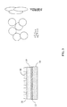
- the DVC microstructure is characterized by a refined microstructure with fine grains as compared to standard YSZ coatings. While standard YSZ coatings also may exhibit a vertically cracked microstructure, the grain size is larger because of the size of the powder particles and the method used to apply the powder particles. YSZ coatings are applied by an air plasma spray process, and the particles typically have an average size in the 40-50 ⁇ m range. The particles tend to splat on contact with the substrate, leaving a relatively large grain size in which the grains have a pancake shape. While the coating will form cracks to relieve internal stresses and the cracks will be substantially vertical, the mean distance between the cracks is determined by the grain size, as depicted in Figure 3 , top right side.
- Coatings in accordance with the present invention are applied by a Suspension Plasma Spray Process utilizing powders that have an average size of 0.5-5 ⁇ m, which is at least a factor of 10 smaller than powders used for YSZ coatings.
- the Suspension Plasma Spray process of the present invention is shown generically in Figure 1 .
- Figure 2 shows various applications for Suspension Thermal Spray, the high temperature axial plasma spray process being used in the present invention because of the high melting temperatures of the thermal barrier coating powders used in the TBC of the present invention.
- the Suspension Plasma Spray Process does cause partial melting of the particles, and while the fine particles exhibit some deformation, the degree of deformation of these smaller particles is less pronounced and the fine powder size yields a fine grained microstructure, as shown in figure 3 , right side bottom.
- This coating will also crack vertically to relieve internal stresses, and once again, the mean distance between cracks is determined by grain size. However, because the average grain size is significantly smaller, the mean distance between cracks is also reduced and the density of cracks is increased. Because the grains are smaller, the path of the cracks is less tortuous resulting in a less circuitous vertical pathway.
- the fine grains and dense crack pattern contribute to strain tolerance and resistance to further crack initiation and crack propagation.
- the coating produced by the methods of the invention are more capable of withstanding solid particle impact, rubs resulting from transients producing blade cutting into the shroud/casing and foreign object impact while sustaining less damage than prior art YSZ coatings.
- the fine grain size is a direct result of the fine powders obtained by reverse co-precipitation and the suspension plasma spray application of the fine powders, producing a softer material with better strain tolerance.
- the grain size is directly related to the size of the powders produced by the co-precipitation process. If a crack is introduced by any of these common mechanisms, the fine grains produce a tortuous path to inhibit crack propagation along the particle/particle interfaces.
- the powders are made using a reverse co-precipitation process.
- the reverse co-precipitation process provides better control of the morphology of the multiple precipitates that are produced, while rendering optimized particle sizes.
- Reverse co-precipitation is initiated in a strong basic reaction solution.
- a reverse co-precipitation reaction results in better control of morphology, size crystalline phase and chemical composition of the final precipitate.
- the method for providing the fine grained particles first involves fabricating the composition used for the TBC as a powder. All of the preferred compositions set forth in Table 1 are fabricated as powder by the same reverse co-precipitation process.
- the reverse co-precipitation process permits better control of the rate of the reaction while formulating these multi-cation systems with the advantage of higher cation homogeneity in the precursor solution.
- Yb-Zr-based oxide compositions, Yb 2 O 3 , Yb-Y-Hf-Ta-Zr, produced by the reverse co-precipitation process comprise about 30-40% by weight Yb and about 30-40% by weight lanthana.
- compositions may further include hafnia (HfO 2 ) and/or tantala (Ta 2 O 5 ) a non-limiting example of which is 30.5% by weight Yb, 24.8% by weight lanthana, 1.4% by weight hafnia, 1.5% by weight tantala and the balance zironia and incidental impurities. Unless otherwise specified herein, all compositional ranges are identified as weight percentages.
- the term "balance essentially zirconia” is used to include, in addition to zirconia, small amounts of impurities and other incidental elements, some of which have been described above, that are inherent in such TBC coating compositions, which in character and/or amount do not affect the advantageous aspects of the coating compositions.
- La 2 O 3 and 4-5% Y 2 O 3 powders were prepared by reverse co-precipitation in such a manner that the precipitation reaction occurs in a strong basic reaction environment having a pH in the range of 10-13.
- This basic reaction environment allows for better control of the hydrolysis-complex process, resulting in a better control of morphology, size, crystalline phase and chemical composition of the final precipitate.
- oxides of the powders with the desired molar ratio were dissolved in a nitric acid and distilled water mix at an elevated temperature, preferably 176- 203° F, (80-95° C), and most preferably 194° F (90° C). The solution was stirred for a predetermined period of time to assure the complete dissolution of the powder.
- the concentration of the solution was adjusted to 0.1M.
- Ammonium hydroxide having a concentration of 1M was then prepared.
- the solution of powder and nitric acid was added to the ammonium hydroxide solution in a drop-wise fashion at a rate of 1-3 ml/min., allowing the ammonium hydroxide to react with the powder solution.
- cations of Zr 4 + , Y 3 + , Yb 3 + and/or La 3 + can co-precipitate, providing a stoichiometric and homogenous composition.
- This co-precipitation permits the formation of complex powders at low temperatures from precursor materials having mixed uniformity at the molecular level. While the reverse co-precipitation reaction is set forth as a batch process, it will be understood that the reaction can be maintained as a continuous process by proper replenishment of the ammonium hydroxide while maintaining pH in the required range as the powder solution is added.
- the precipitate is filtered from the solution and then washed three times with deionized water.
- the washed precipitate is then dried at an elevated temperature, preferably 194° F (90° C) for about 12 hours, yielding nano-sized particles having a size range of about 20-30 nanometers (nm).
- These particles were then calcined at an elevated temperature in the range of 1300-1850° F (700-1000° C), preferably about 1475° F (800° C), in air for 1-4 hours. After calcining, the powder size increased to a size in the range of 1-5 microns ( ⁇ m). At lower temperatures and shorter times, the hydroxides form precipitates of corresponding oxides, which are amorphous in nature. However, with increasing temperature and time, the crystallinity of the precipitates increases.
- the calcined precipitate particles are ball milled into a powder.
- Wet ball milling was carried out in polyurethane containers using YSZ balls as the milling media.
- a ratio of 1:15 or powder:media was used in a liquid carrier, preferably ethanol.
- the ratio powder to ethanol preferably was 1.0:5 (by weight).
- Milling was carried out for about 5 hours.
- the product was then dried for a predetermined period of time at a predetermined temperature to evaporate the carrier. For ethanol, a preferred temperature is about 195° F (90° C) for about 5 hours.
- the dried powders were then hand ground for a sufficient length of time to remove any soft agglomerates, preferably about 3 minutes.
- the dried powders were compressed to form pellets using a 15 mm die with compaction pressures of 10,000 psi. Dies of different sizes requiring different pressures may be used to form pellets of different sizes from a sample of the powders, if desired.
- the pellets were then isostatically pressed under pressures of 25 bars and sintered in air to form pellets of about the same size as the die.
- the pellets are then analyzed for phase structure by a microscopic evaluation. Once it is determined that the sintered pellets have the proper phase structure, the thermal conductivity of the pellets are measured. After confirmation of thermal conductivity of a material lot, if performed, the powders may be classified by size.
- the particles are ready for application as a thermal barrier coating.
- a preferred method for achieving such a structure is a Suspension Plasma Spray operation utilizing a plasma gun.
- Powders of a predetermined size are suspended in a carrier liquid.
- Any liquid carrier such as organic solvents including for example, alcohol, trichloroethane (TCA) trichlorethylene (TCE), acetone, or even water may be used.
- the particles are micron sized particles.
- the suspension of powders of a predetermined size distribution range provides a known size of particles to the plasma spray unit.
- particles having a size distribution of about 0.5-5 ⁇ m are suspended in ethanol.
- the preferred power of the plasma torch is about 100 watts
- nitrogen is the atomizing gas
- the suspension feed rate is about 25 grams/minute
- the speed of the torch across the substrate is about 600 mm/sec
- the spray distances between the torch nozzle and the substrate is between about 50-100 meters.
- different sized particles, different atomizing gases and different carrier liquids may utilize different settings.
- the particles and the carrier liquid are atomized and the carrier liquid is vaporized while the particles are at least partially melted. The particles are directed to the substrate.
- the substrate may be provided with an MCrAlY bond coat, where M is an element selected from nickel (Ni), cobalt (Co), chromium (Cr) and combinations thereof.
- M is an element selected from nickel (Ni), cobalt (Co), chromium (Cr) and combinations thereof.
- plasma spray devices and their methods deliver coating particles to the article substrate at higher temperatures, although at lower velocities.
- the suspended pellets which were characterized to provide a predetermined size distribution, are at least partially melted by the plasma prior to delivery to the substrate surface.
- the plasma spray processes are uniquely suited to provide sufficient energy to at least partially melt the high melting point ceramics of the present invention to provide a structure that is thin and dense, but which still retains a fine grain structure as the melted particles substantially freeze on impact without experiencing grain growth.
- Figure 3 depicts an embodiment of the present invention applied to a substrate 10 depicting an outer layer 16 in the form of abradable ridges 18 comprising a porous TBC and an inner dense vertically cracked (DVC) TBC of the present invention comprising an inner layer 14.
- the inner layer 14 is applied over a bond coat 12, such as the previously discussed MCrAlY.
- This embodiment permits an abradable and sacrificial outer layer 16 having ridges 18 to be applied over the substrate 10. Even if this sacrificial outer layer 16 is lost due to blade rubbing as a result of early transients, the inner layer 14 is retained to provide the ultralow thermal conductivity required to protect the substrate 10.
- the coatings of the present invention can be utilized to enhance the performance of the components of the turbine engine, and hence the turbine engine in any one of several different ways.
- any one of the coatings of the present invention can be substituted for standard YSZ coatings, improving the performance of the turbine engine components.
- the coatings may also be used in combination with one another to improve performance.
- one of the stronger coatings, the group 2 coatings may be applied over the more erosion resistant coatings, the group 1 coatings.
- the group 2 coatings can be relied upon for abrasion resistance during early stages of turbine operation as wear-in occurs.
- either one or both of the group 1 and group 2 coatings may be applied over YSZ.
- the YSZ may be maintained below 2200° F thereby extending its life.
- powders of group 1 and group 2 may be mixed together to formulate one or more coatings have preselected thermal conductivity, erosion, hardness, fracture toughness and tensile properties. These "blended" compositions may be applied over the component substrate or over a YSZ coating.
- YSZ powder may be blended with one or more of the "blended" compositions to provide preselected thermal conductivity, erosion, hardness, fracture toughness and tensile properties.
- a thermal barrier coating was formed by spraying a flashcoat of 7-YSZ over a NiCrAlY bondcoat. Then, a coating from Group 1 was applied over the 7-YSZ layer, and a coating from Group 2 was applied over the Group 1 layer. Both Group 1 and Group 2 layers were applied by solution plasma spray. In first example, the Group 1 and Group 2 layers were applied to a total thickness of 10 mils (0.010"). In a second embodiment, the Group 1 and Group 2 coatings were applied to a total thickness of 35 mils (0.035"). The plasma power was maintained at 53 kW for application of the powders of Group 1 and Group 2, which was sufficient to partially melt the powders. Although the substrate temperature was not monitored, because of the low wattage, the temperature was quite low as compared to powder applications applied by the DVC process.
- the present invention provides coatings having low thermal conductivity and ultra-low conductivity to be used in higher temperature applications in which prior art YSZ coatings destabilized as their erosion resistance and abrasion resistance degraded.
- the Yb 2 O 3 coatings and the Yb/Y/Hf/Ta/Zr coatings when applied in accordance with the methods of the present invention, retain excellent erosion resistance and abrasion resistance.
- These DVC TBCs have superior low conductivity so as to improve the performance of the base material by at least 25° F, and can lead to an improvement of 50% in the life of the base material.
- the TBC of the present invention may allow the base material to be utilized in an application having higher operating temperatures without affecting the life of the base material, while providing higher operating efficiency to the turbomachinery.
- the fine grain size provides toughness and strain compliance, reducing crack initiation and propagation.
Landscapes
- Chemical & Material Sciences (AREA)
- Engineering & Computer Science (AREA)
- Materials Engineering (AREA)
- Organic Chemistry (AREA)
- Mechanical Engineering (AREA)
- Chemical Kinetics & Catalysis (AREA)
- Metallurgy (AREA)
- Ceramic Engineering (AREA)
- Physics & Mathematics (AREA)
- Plasma & Fusion (AREA)
- Inorganic Chemistry (AREA)
- Manufacturing & Machinery (AREA)
- Structural Engineering (AREA)
- Composite Materials (AREA)
- General Engineering & Computer Science (AREA)
- Coating By Spraying Or Casting (AREA)
- Turbine Rotor Nozzle Sealing (AREA)
Applications Claiming Priority (1)
| Application Number | Priority Date | Filing Date | Title |
|---|---|---|---|
| US13/860,044 US9816392B2 (en) | 2013-04-10 | 2013-04-10 | Architectures for high temperature TBCs with ultra low thermal conductivity and abradability and method of making |
Publications (3)
| Publication Number | Publication Date |
|---|---|
| EP2799588A2 true EP2799588A2 (de) | 2014-11-05 |
| EP2799588A3 EP2799588A3 (de) | 2015-04-29 |
| EP2799588B1 EP2799588B1 (de) | 2019-01-30 |
Family
ID=50828661
Family Applications (1)
| Application Number | Title | Priority Date | Filing Date |
|---|---|---|---|
| EP14163745.4A Active EP2799588B1 (de) | 2013-04-10 | 2014-04-07 | Verfahren zur Herstellung von Hochtemperatur-TBCs mit ultraniedriger Wärmeleitfähigkeit und Zerreibbarkeit |
Country Status (4)
| Country | Link |
|---|---|
| US (1) | US9816392B2 (de) |
| EP (1) | EP2799588B1 (de) |
| JP (1) | JP6608580B2 (de) |
| CN (1) | CN104096846B (de) |
Cited By (2)
| Publication number | Priority date | Publication date | Assignee | Title |
|---|---|---|---|---|
| FR3029813A1 (fr) * | 2014-12-16 | 2016-06-17 | Airbus Operations Sas | Procede de fabrication d'un revetement microstructure, et paroi presentant un tel revetement |
| CN113087521A (zh) * | 2019-12-23 | 2021-07-09 | 中国科学院上海硅酸盐研究所 | 一种晶粒形貌可控的热障涂层的制备方法 |
Families Citing this family (13)
| Publication number | Priority date | Publication date | Assignee | Title |
|---|---|---|---|---|
| US10196728B2 (en) * | 2014-05-16 | 2019-02-05 | Applied Materials, Inc. | Plasma spray coating design using phase and stress control |
| US10436042B2 (en) * | 2015-12-01 | 2019-10-08 | United Technologies Corporation | Thermal barrier coatings and methods |
| DE102016002630A1 (de) * | 2016-03-07 | 2017-09-07 | Forschungszentrum Jülich GmbH | Haftvermittlerschicht zur Anbindung einer Hochtemperaturschutzschicht auf einem Substrat, sowie Verfahren zur Herstellung derselben |
| US10822966B2 (en) * | 2016-05-09 | 2020-11-03 | General Electric Company | Thermal barrier system with bond coat barrier |
| JP6908973B2 (ja) * | 2016-06-08 | 2021-07-28 | 三菱重工業株式会社 | 遮熱コーティング、タービン部材、ガスタービン、ならびに遮熱コーティングの製造方法 |
| US10934626B2 (en) * | 2017-04-21 | 2021-03-02 | General Electric Company | Segmented environmental barrier coating systems and methods of forming the same |
| JP6821496B2 (ja) * | 2017-04-26 | 2021-01-27 | 三菱重工業株式会社 | 遮熱コーティング形成方法、遮熱コーティング、及び高温部材 |
| JP6896498B2 (ja) * | 2017-04-26 | 2021-06-30 | 三菱重工業株式会社 | 遮熱コーティング形成方法、遮熱コーティング、及び高温部材 |
| US20200048751A1 (en) * | 2017-04-26 | 2020-02-13 | Mitsubishi Heavy Industries, Ltd. | Thermal barrier coating formation method, thermal barrier coating, and high-temperature member |
| JP2019151927A (ja) * | 2018-03-02 | 2019-09-12 | 一般財団法人ファインセラミックスセンター | 遮熱コーティング用材料及び物品 |
| JP2019157216A (ja) * | 2018-03-14 | 2019-09-19 | 三菱重工業株式会社 | セラミックコーティング、タービン部材、ガスタービン及びセラミックコーティングの製造方法 |
| CN114015963B (zh) * | 2021-11-09 | 2023-09-08 | 内蒙古工业大学 | 一种具有垂直裂缝结构的低热导率热障涂层及其制备方法 |
| CN117327416B (zh) * | 2023-09-28 | 2025-10-03 | 中国科学院赣江创新研究院 | 一种热障涂层材料及其制备方法、热障涂层及其应用 |
Family Cites Families (31)
| Publication number | Priority date | Publication date | Assignee | Title |
|---|---|---|---|---|
| US4299865A (en) | 1979-09-06 | 1981-11-10 | General Motors Corporation | Abradable ceramic seal and method of making same |
| US4764089A (en) | 1986-08-07 | 1988-08-16 | Allied-Signal Inc. | Abradable strain-tolerant ceramic coated turbine shroud |
| US4914794A (en) | 1986-08-07 | 1990-04-10 | Allied-Signal Inc. | Method of making an abradable strain-tolerant ceramic coated turbine shroud |
| JP2607517B2 (ja) * | 1987-05-21 | 1997-05-07 | 株式会社デンソー | ジルコニアセラミックスの製造方法 |
| CN1062204C (zh) * | 1994-12-29 | 2001-02-21 | 武汉工业大学 | 氧化锆等离子喷涂粉末的制备方法 |
| US6641907B1 (en) | 1999-12-20 | 2003-11-04 | Siemens Westinghouse Power Corporation | High temperature erosion resistant coating and material containing compacted hollow geometric shapes |
| US6733907B2 (en) | 1998-03-27 | 2004-05-11 | Siemens Westinghouse Power Corporation | Hybrid ceramic material composed of insulating and structural ceramic layers |
| US6235370B1 (en) | 1999-03-03 | 2001-05-22 | Siemens Westinghouse Power Corporation | High temperature erosion resistant, abradable thermal barrier composite coating |
| US20030180571A1 (en) * | 1999-12-14 | 2003-09-25 | The Penn State Research Foundation | Microstructured coatings and materials |
| US6670046B1 (en) | 2000-08-31 | 2003-12-30 | Siemens Westinghouse Power Corporation | Thermal barrier coating system for turbine components |
| JP3952252B2 (ja) * | 2001-01-25 | 2007-08-01 | 株式会社フジミインコーポレーテッド | 溶射用粉末およびそれを用いた高速フレーム溶射方法 |
| US20090258247A1 (en) | 2008-04-11 | 2009-10-15 | Siemens Power Generation, Inc. | Anisotropic Soft Ceramics for Abradable Coatings in Gas Turbines |
| US7541005B2 (en) * | 2001-09-26 | 2009-06-02 | Siemens Energy Inc. | Catalytic thermal barrier coatings |
| US7060365B2 (en) * | 2002-05-30 | 2006-06-13 | General Electric Company | Thermal barrier coating material |
| US6916529B2 (en) | 2003-01-09 | 2005-07-12 | General Electric Company | High temperature, oxidation-resistant abradable coatings containing microballoons and method for applying same |
| US6982126B2 (en) * | 2003-11-26 | 2006-01-03 | General Electric Company | Thermal barrier coating |
| US6858334B1 (en) * | 2003-12-30 | 2005-02-22 | General Electric Company | Ceramic compositions for low conductivity thermal barrier coatings |
| US20050142393A1 (en) | 2003-12-30 | 2005-06-30 | Boutwell Brett A. | Ceramic compositions for thermal barrier coatings stabilized in the cubic crystalline phase |
| US7364802B2 (en) * | 2003-12-30 | 2008-04-29 | General Electric Company | Ceramic compositions useful in thermal barrier coatings having reduced thermal conductivity |
| US7126329B2 (en) | 2004-01-21 | 2006-10-24 | General Electric Company | Methods for preparing and testing a thermal-spray coated substrate |
| US7476453B2 (en) * | 2004-12-06 | 2009-01-13 | General Electric Company | Low thermal conductivity thermal barrier coating system and method therefor |
| US20070082131A1 (en) | 2005-10-07 | 2007-04-12 | Sulzer Metco (Us), Inc. | Optimized high purity coating for high temperature thermal cycling applications |
| US7504157B2 (en) | 2005-11-02 | 2009-03-17 | H.C. Starck Gmbh | Strontium titanium oxides and abradable coatings made therefrom |
| WO2007121556A1 (en) | 2006-04-25 | 2007-11-01 | National Research Counsil Of Canada | Thermal spray coating of porous nanostructured ceramic feedstock |
| US8153204B2 (en) | 2007-09-19 | 2012-04-10 | Siemens Energy, Inc. | Imparting functional characteristics to engine portions |
| JP2009161789A (ja) * | 2007-12-28 | 2009-07-23 | Riverstone Kogyo Kk | セラミックス溶射皮膜とその製造法 |
| US8546284B2 (en) | 2008-05-07 | 2013-10-01 | Council Of Scientific & Industrial Research | Process for the production of plasma sprayable yttria stabilized zirconia (YSZ) and plasma sprayable YSZ powder produced thereby |
| EP2141328A1 (de) | 2008-07-03 | 2010-01-06 | Siemens Aktiengesellschaft | Dichtungssystem zwischen einem Mantelringsegment und einer Laufschaufelspitze und Herstellungsverfahren für ein solches Segment |
| US20100069226A1 (en) | 2008-09-17 | 2010-03-18 | General Electric Company | Rare earth phosphate bonded ceramics |
| US8470460B2 (en) * | 2008-11-25 | 2013-06-25 | Rolls-Royce Corporation | Multilayer thermal barrier coatings |
| US8579581B2 (en) * | 2010-09-15 | 2013-11-12 | General Electric Company | Abradable bucket shroud |
-
2013
- 2013-04-10 US US13/860,044 patent/US9816392B2/en active Active
-
2014
- 2014-04-07 EP EP14163745.4A patent/EP2799588B1/de active Active
- 2014-04-08 JP JP2014079054A patent/JP6608580B2/ja active Active
- 2014-04-10 CN CN201410142770.XA patent/CN104096846B/zh active Active
Non-Patent Citations (1)
| Title |
|---|
| None |
Cited By (2)
| Publication number | Priority date | Publication date | Assignee | Title |
|---|---|---|---|---|
| FR3029813A1 (fr) * | 2014-12-16 | 2016-06-17 | Airbus Operations Sas | Procede de fabrication d'un revetement microstructure, et paroi presentant un tel revetement |
| CN113087521A (zh) * | 2019-12-23 | 2021-07-09 | 中国科学院上海硅酸盐研究所 | 一种晶粒形貌可控的热障涂层的制备方法 |
Also Published As
| Publication number | Publication date |
|---|---|
| US9816392B2 (en) | 2017-11-14 |
| JP2014205913A (ja) | 2014-10-30 |
| CN104096846A (zh) | 2014-10-15 |
| EP2799588A3 (de) | 2015-04-29 |
| EP2799588B1 (de) | 2019-01-30 |
| JP6608580B2 (ja) | 2019-11-20 |
| CN104096846B (zh) | 2019-05-17 |
| US20140308479A1 (en) | 2014-10-16 |
Similar Documents
| Publication | Publication Date | Title |
|---|---|---|
| EP2799588B1 (de) | Verfahren zur Herstellung von Hochtemperatur-TBCs mit ultraniedriger Wärmeleitfähigkeit und Zerreibbarkeit | |
| US7597971B2 (en) | Thermal barrier coating material | |
| US7563503B2 (en) | Coatings, materials, articles, and methods of making thereof | |
| EP2371987B1 (de) | Wärmesperrenbeschichtungselement, herstellungsverfahren dafür, verwendung des wärmesperrenbeschichtungsmaterials, gasturbine und gesinterter körper | |
| EP1959099B1 (de) | Ein Verfahren zur Herstellung eines mit einer Wärmedämmung beschichteten Element | |
| JP5635589B2 (ja) | 溶射によってターゲットを製造するための方法 | |
| EP1375701B1 (de) | Wärmedämmschichtmaterial | |
| US20150233256A1 (en) | Novel architectures for ultra low thermal conductivity thermal barrier coatings with improved erosion and impact properties | |
| US20110171488A1 (en) | Thermal barrier coating systems | |
| US9139477B2 (en) | Ceramic powders and methods therefor | |
| CN106884132A (zh) | 一种高温热障涂层材料 | |
| CN101723667A (zh) | 带有网状裂纹结构的多元稀土氧化物掺杂氧化锆热障涂层及其制备方法 | |
| CN114000089A (zh) | 一种利用aps技术制备的高熵氧化物超高温热障涂层及其方法 | |
| US20090258247A1 (en) | Anisotropic Soft Ceramics for Abradable Coatings in Gas Turbines | |
| KR101466967B1 (ko) | 내식성이 향상된 다성분계 열용사용 코팅물질, 그 제조방법 및 코팅방법 | |
| CN101948995B (zh) | 一种陶瓷复合热障涂层材料 | |
| CN114231886B (zh) | 一种高温长寿命ysz涂层及其制备方法 | |
| EP1829824A1 (de) | Teillegiertes Zirkoniapulver | |
| KR101189184B1 (ko) | 열차폐 코팅용 소결체, 그 제조방법 및 이를 이용한 이중의 열차폐 코팅층의 제조방법 | |
| Di Girolamo et al. | Microstructure and thermal properties of plasma-sprayed ceramic thermal barrier coatings | |
| JP5606125B2 (ja) | 溶射粉末の製造方法、タービン部材及びガスタービン | |
| Pasupuleti et al. | Thermal fatigue characteristics of 8Y2O3-ZrO2, La2Zr2O7, La2 (Zr0. 7Ce0. 3) 2O7 and La2Ce2O7 thermal barrier coatings in duplex, multilayer functionally graded and multilayer configurations | |
| JP2009280854A (ja) | セラミックス膜とその製造方法、及び遮熱コーティング構造 | |
| Ma et al. | Study of unique microstructure in SPS ceramic nanocoatings | |
| Sttiver et al. | TazOs/NbZO5 and Y203 Co-doped Zirconias for Thermal Barrier Coatings |
Legal Events
| Date | Code | Title | Description |
|---|---|---|---|
| PUAI | Public reference made under article 153(3) epc to a published international application that has entered the european phase |
Free format text: ORIGINAL CODE: 0009012 |
|
| 17P | Request for examination filed |
Effective date: 20140407 |
|
| AK | Designated contracting states |
Kind code of ref document: A2 Designated state(s): AL AT BE BG CH CY CZ DE DK EE ES FI FR GB GR HR HU IE IS IT LI LT LU LV MC MK MT NL NO PL PT RO RS SE SI SK SM TR |
|
| AX | Request for extension of the european patent |
Extension state: BA ME |
|
| PUAL | Search report despatched |
Free format text: ORIGINAL CODE: 0009013 |
|
| AK | Designated contracting states |
Kind code of ref document: A3 Designated state(s): AL AT BE BG CH CY CZ DE DK EE ES FI FR GB GR HR HU IE IS IT LI LT LU LV MC MK MT NL NO PL PT RO RS SE SI SK SM TR |
|
| AX | Request for extension of the european patent |
Extension state: BA ME |
|
| RIC1 | Information provided on ipc code assigned before grant |
Ipc: C23C 28/00 20060101ALI20150324BHEP Ipc: C23C 4/12 20060101AFI20150324BHEP Ipc: F01D 5/28 20060101ALI20150324BHEP Ipc: C23C 28/04 20060101ALI20150324BHEP Ipc: C04B 35/486 20060101ALI20150324BHEP |
|
| R17P | Request for examination filed (corrected) |
Effective date: 20151029 |
|
| RBV | Designated contracting states (corrected) |
Designated state(s): AL AT BE BG CH CY CZ DE DK EE ES FI FR GB GR HR HU IE IS IT LI LT LU LV MC MK MT NL NO PL PT RO RS SE SI SK SM TR |
|
| 17Q | First examination report despatched |
Effective date: 20160308 |
|
| STAA | Information on the status of an ep patent application or granted ep patent |
Free format text: STATUS: EXAMINATION IS IN PROGRESS |
|
| REG | Reference to a national code |
Ref country code: DE Ref legal event code: R079 Ref document number: 602014040257 Country of ref document: DE Free format text: PREVIOUS MAIN CLASS: C23C0004120000 Ipc: C23C0004110000 |
|
| GRAP | Despatch of communication of intention to grant a patent |
Free format text: ORIGINAL CODE: EPIDOSNIGR1 |
|
| STAA | Information on the status of an ep patent application or granted ep patent |
Free format text: STATUS: GRANT OF PATENT IS INTENDED |
|
| RIC1 | Information provided on ipc code assigned before grant |
Ipc: C23C 28/04 20060101ALI20180716BHEP Ipc: C23C 4/134 20160101ALI20180716BHEP Ipc: C23C 28/00 20060101ALI20180716BHEP Ipc: C23C 4/12 20160101ALI20180716BHEP Ipc: F01D 5/28 20060101ALI20180716BHEP Ipc: C04B 35/486 20060101ALI20180716BHEP Ipc: C23C 4/11 20160101AFI20180716BHEP |
|
| INTG | Intention to grant announced |
Effective date: 20180807 |
|
| GRAS | Grant fee paid |
Free format text: ORIGINAL CODE: EPIDOSNIGR3 |
|
| GRAA | (expected) grant |
Free format text: ORIGINAL CODE: 0009210 |
|
| STAA | Information on the status of an ep patent application or granted ep patent |
Free format text: STATUS: THE PATENT HAS BEEN GRANTED |
|
| AK | Designated contracting states |
Kind code of ref document: B1 Designated state(s): AL AT BE BG CH CY CZ DE DK EE ES FI FR GB GR HR HU IE IS IT LI LT LU LV MC MK MT NL NO PL PT RO RS SE SI SK SM TR |
|
| REG | Reference to a national code |
Ref country code: GB Ref legal event code: FG4D |
|
| REG | Reference to a national code |
Ref country code: CH Ref legal event code: EP |
|
| REG | Reference to a national code |
Ref country code: AT Ref legal event code: REF Ref document number: 1093329 Country of ref document: AT Kind code of ref document: T Effective date: 20190215 |
|
| REG | Reference to a national code |
Ref country code: IE Ref legal event code: FG4D |
|
| REG | Reference to a national code |
Ref country code: DE Ref legal event code: R096 Ref document number: 602014040257 Country of ref document: DE |
|
| REG | Reference to a national code |
Ref country code: CH Ref legal event code: NV Representative=s name: VALIPAT S.A. GEVERS SA, CH |
|
| REG | Reference to a national code |
Ref country code: CH Ref legal event code: PCAR Free format text: NEW ADDRESS: RUE DES NOYERS 11, 2000 NEUCHATEL (CH) |
|
| REG | Reference to a national code |
Ref country code: LT Ref legal event code: MG4D |
|
| REG | Reference to a national code |
Ref country code: NL Ref legal event code: MP Effective date: 20190130 |
|
| PG25 | Lapsed in a contracting state [announced via postgrant information from national office to epo] |
Ref country code: SE Free format text: LAPSE BECAUSE OF FAILURE TO SUBMIT A TRANSLATION OF THE DESCRIPTION OR TO PAY THE FEE WITHIN THE PRESCRIBED TIME-LIMIT Effective date: 20190130 Ref country code: NL Free format text: LAPSE BECAUSE OF FAILURE TO SUBMIT A TRANSLATION OF THE DESCRIPTION OR TO PAY THE FEE WITHIN THE PRESCRIBED TIME-LIMIT Effective date: 20190130 Ref country code: ES Free format text: LAPSE BECAUSE OF FAILURE TO SUBMIT A TRANSLATION OF THE DESCRIPTION OR TO PAY THE FEE WITHIN THE PRESCRIBED TIME-LIMIT Effective date: 20190130 Ref country code: PL Free format text: LAPSE BECAUSE OF FAILURE TO SUBMIT A TRANSLATION OF THE DESCRIPTION OR TO PAY THE FEE WITHIN THE PRESCRIBED TIME-LIMIT Effective date: 20190130 Ref country code: LT Free format text: LAPSE BECAUSE OF FAILURE TO SUBMIT A TRANSLATION OF THE DESCRIPTION OR TO PAY THE FEE WITHIN THE PRESCRIBED TIME-LIMIT Effective date: 20190130 Ref country code: FI Free format text: LAPSE BECAUSE OF FAILURE TO SUBMIT A TRANSLATION OF THE DESCRIPTION OR TO PAY THE FEE WITHIN THE PRESCRIBED TIME-LIMIT Effective date: 20190130 Ref country code: NO Free format text: LAPSE BECAUSE OF FAILURE TO SUBMIT A TRANSLATION OF THE DESCRIPTION OR TO PAY THE FEE WITHIN THE PRESCRIBED TIME-LIMIT Effective date: 20190430 Ref country code: PT Free format text: LAPSE BECAUSE OF FAILURE TO SUBMIT A TRANSLATION OF THE DESCRIPTION OR TO PAY THE FEE WITHIN THE PRESCRIBED TIME-LIMIT Effective date: 20190530 |
|
| REG | Reference to a national code |
Ref country code: AT Ref legal event code: MK05 Ref document number: 1093329 Country of ref document: AT Kind code of ref document: T Effective date: 20190130 |
|
| PG25 | Lapsed in a contracting state [announced via postgrant information from national office to epo] |
Ref country code: BG Free format text: LAPSE BECAUSE OF FAILURE TO SUBMIT A TRANSLATION OF THE DESCRIPTION OR TO PAY THE FEE WITHIN THE PRESCRIBED TIME-LIMIT Effective date: 20190430 Ref country code: LV Free format text: LAPSE BECAUSE OF FAILURE TO SUBMIT A TRANSLATION OF THE DESCRIPTION OR TO PAY THE FEE WITHIN THE PRESCRIBED TIME-LIMIT Effective date: 20190130 Ref country code: IS Free format text: LAPSE BECAUSE OF FAILURE TO SUBMIT A TRANSLATION OF THE DESCRIPTION OR TO PAY THE FEE WITHIN THE PRESCRIBED TIME-LIMIT Effective date: 20190530 Ref country code: HR Free format text: LAPSE BECAUSE OF FAILURE TO SUBMIT A TRANSLATION OF THE DESCRIPTION OR TO PAY THE FEE WITHIN THE PRESCRIBED TIME-LIMIT Effective date: 20190130 Ref country code: RS Free format text: LAPSE BECAUSE OF FAILURE TO SUBMIT A TRANSLATION OF THE DESCRIPTION OR TO PAY THE FEE WITHIN THE PRESCRIBED TIME-LIMIT Effective date: 20190130 Ref country code: GR Free format text: LAPSE BECAUSE OF FAILURE TO SUBMIT A TRANSLATION OF THE DESCRIPTION OR TO PAY THE FEE WITHIN THE PRESCRIBED TIME-LIMIT Effective date: 20190501 |
|
| PG25 | Lapsed in a contracting state [announced via postgrant information from national office to epo] |
Ref country code: AL Free format text: LAPSE BECAUSE OF FAILURE TO SUBMIT A TRANSLATION OF THE DESCRIPTION OR TO PAY THE FEE WITHIN THE PRESCRIBED TIME-LIMIT Effective date: 20190130 Ref country code: CZ Free format text: LAPSE BECAUSE OF FAILURE TO SUBMIT A TRANSLATION OF THE DESCRIPTION OR TO PAY THE FEE WITHIN THE PRESCRIBED TIME-LIMIT Effective date: 20190130 Ref country code: RO Free format text: LAPSE BECAUSE OF FAILURE TO SUBMIT A TRANSLATION OF THE DESCRIPTION OR TO PAY THE FEE WITHIN THE PRESCRIBED TIME-LIMIT Effective date: 20190130 Ref country code: SK Free format text: LAPSE BECAUSE OF FAILURE TO SUBMIT A TRANSLATION OF THE DESCRIPTION OR TO PAY THE FEE WITHIN THE PRESCRIBED TIME-LIMIT Effective date: 20190130 Ref country code: EE Free format text: LAPSE BECAUSE OF FAILURE TO SUBMIT A TRANSLATION OF THE DESCRIPTION OR TO PAY THE FEE WITHIN THE PRESCRIBED TIME-LIMIT Effective date: 20190130 Ref country code: DK Free format text: LAPSE BECAUSE OF FAILURE TO SUBMIT A TRANSLATION OF THE DESCRIPTION OR TO PAY THE FEE WITHIN THE PRESCRIBED TIME-LIMIT Effective date: 20190130 |
|
| REG | Reference to a national code |
Ref country code: DE Ref legal event code: R097 Ref document number: 602014040257 Country of ref document: DE |
|
| PG25 | Lapsed in a contracting state [announced via postgrant information from national office to epo] |
Ref country code: SM Free format text: LAPSE BECAUSE OF FAILURE TO SUBMIT A TRANSLATION OF THE DESCRIPTION OR TO PAY THE FEE WITHIN THE PRESCRIBED TIME-LIMIT Effective date: 20190130 |
|
| PLBE | No opposition filed within time limit |
Free format text: ORIGINAL CODE: 0009261 |
|
| STAA | Information on the status of an ep patent application or granted ep patent |
Free format text: STATUS: NO OPPOSITION FILED WITHIN TIME LIMIT |
|
| REG | Reference to a national code |
Ref country code: BE Ref legal event code: MM Effective date: 20190430 |
|
| PG25 | Lapsed in a contracting state [announced via postgrant information from national office to epo] |
Ref country code: AT Free format text: LAPSE BECAUSE OF FAILURE TO SUBMIT A TRANSLATION OF THE DESCRIPTION OR TO PAY THE FEE WITHIN THE PRESCRIBED TIME-LIMIT Effective date: 20190130 Ref country code: MC Free format text: LAPSE BECAUSE OF FAILURE TO SUBMIT A TRANSLATION OF THE DESCRIPTION OR TO PAY THE FEE WITHIN THE PRESCRIBED TIME-LIMIT Effective date: 20190130 Ref country code: LU Free format text: LAPSE BECAUSE OF NON-PAYMENT OF DUE FEES Effective date: 20190407 |
|
| 26N | No opposition filed |
Effective date: 20191031 |
|
| PG25 | Lapsed in a contracting state [announced via postgrant information from national office to epo] |
Ref country code: SI Free format text: LAPSE BECAUSE OF FAILURE TO SUBMIT A TRANSLATION OF THE DESCRIPTION OR TO PAY THE FEE WITHIN THE PRESCRIBED TIME-LIMIT Effective date: 20190130 Ref country code: BE Free format text: LAPSE BECAUSE OF NON-PAYMENT OF DUE FEES Effective date: 20190430 |
|
| PG25 | Lapsed in a contracting state [announced via postgrant information from national office to epo] |
Ref country code: TR Free format text: LAPSE BECAUSE OF FAILURE TO SUBMIT A TRANSLATION OF THE DESCRIPTION OR TO PAY THE FEE WITHIN THE PRESCRIBED TIME-LIMIT Effective date: 20190130 |
|
| PG25 | Lapsed in a contracting state [announced via postgrant information from national office to epo] |
Ref country code: IE Free format text: LAPSE BECAUSE OF NON-PAYMENT OF DUE FEES Effective date: 20190407 |
|
| PG25 | Lapsed in a contracting state [announced via postgrant information from national office to epo] |
Ref country code: CY Free format text: LAPSE BECAUSE OF FAILURE TO SUBMIT A TRANSLATION OF THE DESCRIPTION OR TO PAY THE FEE WITHIN THE PRESCRIBED TIME-LIMIT Effective date: 20190130 |
|
| PG25 | Lapsed in a contracting state [announced via postgrant information from national office to epo] |
Ref country code: MT Free format text: LAPSE BECAUSE OF FAILURE TO SUBMIT A TRANSLATION OF THE DESCRIPTION OR TO PAY THE FEE WITHIN THE PRESCRIBED TIME-LIMIT Effective date: 20190130 Ref country code: HU Free format text: LAPSE BECAUSE OF FAILURE TO SUBMIT A TRANSLATION OF THE DESCRIPTION OR TO PAY THE FEE WITHIN THE PRESCRIBED TIME-LIMIT; INVALID AB INITIO Effective date: 20140407 |
|
| PG25 | Lapsed in a contracting state [announced via postgrant information from national office to epo] |
Ref country code: MK Free format text: LAPSE BECAUSE OF FAILURE TO SUBMIT A TRANSLATION OF THE DESCRIPTION OR TO PAY THE FEE WITHIN THE PRESCRIBED TIME-LIMIT Effective date: 20190130 |
|
| P01 | Opt-out of the competence of the unified patent court (upc) registered |
Effective date: 20230522 |
|
| REG | Reference to a national code |
Ref country code: DE Ref legal event code: R081 Ref document number: 602014040257 Country of ref document: DE Owner name: GENERAL ELECTRIC TECHNOLOGY GMBH, CH Free format text: FORMER OWNER: GENERAL ELECTRIC CO., SCHENECTADY, N.Y., US |
|
| REG | Reference to a national code |
Ref country code: GB Ref legal event code: 732E Free format text: REGISTERED BETWEEN 20240222 AND 20240228 |
|
| PGFP | Annual fee paid to national office [announced via postgrant information from national office to epo] |
Ref country code: DE Payment date: 20250319 Year of fee payment: 12 |
|
| PGFP | Annual fee paid to national office [announced via postgrant information from national office to epo] |
Ref country code: CH Payment date: 20250501 Year of fee payment: 12 |
|
| PGFP | Annual fee paid to national office [announced via postgrant information from national office to epo] |
Ref country code: GB Payment date: 20260319 Year of fee payment: 13 |
|
| PGFP | Annual fee paid to national office [announced via postgrant information from national office to epo] |
Ref country code: IT Payment date: 20260319 Year of fee payment: 13 |
|
| PGFP | Annual fee paid to national office [announced via postgrant information from national office to epo] |
Ref country code: FR Payment date: 20260319 Year of fee payment: 13 |