EP2797296A2 - Elektronische Vorrichtung - Google Patents
Elektronische Vorrichtung Download PDFInfo
- Publication number
- EP2797296A2 EP2797296A2 EP14157516.7A EP14157516A EP2797296A2 EP 2797296 A2 EP2797296 A2 EP 2797296A2 EP 14157516 A EP14157516 A EP 14157516A EP 2797296 A2 EP2797296 A2 EP 2797296A2
- Authority
- EP
- European Patent Office
- Prior art keywords
- cam
- rotation axis
- casing
- state
- linking member
- Prior art date
- Legal status (The legal status is an assumption and is not a legal conclusion. Google has not performed a legal analysis and makes no representation as to the accuracy of the status listed.)
- Withdrawn
Links
Images


Classifications
-
- E—FIXED CONSTRUCTIONS
- E05—LOCKS; KEYS; WINDOW OR DOOR FITTINGS; SAFES
- E05D—HINGES OR SUSPENSION DEVICES FOR DOORS, WINDOWS OR WINGS
- E05D3/00—Hinges with pins
- E05D3/06—Hinges with pins with two or more pins
- E05D3/12—Hinges with pins with two or more pins with two parallel pins and one arm
-
- H—ELECTRICITY
- H04—ELECTRIC COMMUNICATION TECHNIQUE
- H04M—TELEPHONIC COMMUNICATION
- H04M1/00—Substation equipment, e.g. for use by subscribers
- H04M1/02—Constructional features of telephone sets
- H04M1/0202—Portable telephone sets, e.g. cordless phones, mobile phones or bar type handsets
- H04M1/0206—Portable telephones comprising a plurality of mechanically joined movable body parts, e.g. hinged housings
- H04M1/0208—Portable telephones comprising a plurality of mechanically joined movable body parts, e.g. hinged housings characterized by the relative motions of the body parts
- H04M1/0214—Foldable telephones, i.e. with body parts pivoting to an open position around an axis parallel to the plane they define in closed position
- H04M1/0216—Foldable in one direction, i.e. using a one degree of freedom hinge
- H04M1/022—The hinge comprising two parallel pivoting axes
Definitions
- the embodiment discussed herein relates to an electronic device.
- Portable electronic devices typified by cell telephones and tablet computers have spread rapidly in recent years.
- electronic devices there are also a large number of electronic devices that employ folding structures for reasons such as compactness.
- An example of a conventional folding structure for an electronic device is a structure that has a single-axis hinge between two casings, in which the two casings open and close by using the hinge rotating.
- an electronic device includes a first casing rotatably supported by a first rotation axis, a second casing rotatably supported by a second rotation axis that is parallel to the first rotation axis, a first cam that is provided on the first rotation axis, rotates about the first rotation axis in accordance with rotation of the first casing, and causes the first casing to move together with the first rotation axis in a direction away from the second rotation axis, a second cam that is provided on the second rotation axis, rotates about the second rotation axis in accordance with rotation of the second casing, and causes the second casing to move together with the second rotation axis in a direction away from the first rotation axis, and an elastic member that applies a force in a direction in which the first rotation axis and the second rotation axis become closer.
- FIG. 1A is a schematic perspective view depicting the closed state of an electronic device according to the embodiment.
- FIG. 1B is a schematic side view depicting the closed state of an electronic device according to the embodiment.
- FIG. 2A is a schematic perspective view depicting the mid-opened/closed state of an electronic device according to the embodiment.
- FIG. 2B is a schematic side view depicting the mid-opened/closed state of an electronic device according to the embodiment.
- FIG. 3A is a schematic perspective view depicting the opened state of an electronic device according to the embodiment.
- FIG. 3B is a schematic side view depicting the opened state of an electronic device according to the embodiment.
- an electronic device 1 has an upper casing 2 and a lower casing 3.
- the upper casing 2 and the lower casing 3 are linked by hinges 1A and 1B.
- the upper casing 2 is an example of a "first casing”.
- the lower casing 3 is an example of a "second casing”.
- the dashed lines in FIG. 1A , FIG. 2A , and FIG. 3A , and the dots in FIG. 1B , FIG. 2B , and FIG. 3B represent the rotation axis 20 of the upper casing 2 and the rotation axis 30 of the lower casing 3.
- the upper casing 2 is rotatably supported about the rotation axis 20 by the hinges 1A and 1B. In other words, as depicted in FIG. 1A to FIG. 3B , the upper casing 2 turns about the rotation axis 20. Furthermore, the lower casing 3 is rotatably supported about the rotation axis 30 by the hinges 1A and 1B. In other words, as depicted in FIG. 1A to FIG. 3B , the lower casing 3 turns about the rotation axis 30.
- the upper casing 2 and the lower casing 3 rotate to a position where the mutual contact surfaces form the same one surface, in other words a position where the mutual contact surfaces are flush.
- This state is hereafter referred to as the completely opened state of the electronic device 1.
- the angle formed by the upper casing 2 and the lower casing 3 at this time is 180 degrees.
- the state during the transition from the closed state of the electronic device 1 to the completely opened state is represented using the angle formed by the upper casing 2 and the lower casing 3.
- the state in FIG. 2A and FIG. 2B is a state in which the electronic device 1 has been opened to 90 degrees.
- FIG. 4 is a perspective view depicting a detailed example of the electronic device.
- FIG. 4 is the completely opened state of the electronic device 1.
- the configurations of the hinge 1A and the hinge 1B are illustrated in more detail.
- a screen 21 and a screen 31 may be arranged on the surfaces of the sides that come into contact in the closed state of the electronic device 1.
- the screen 21 and the screen 31 are arranged side-by-side so as to form the same one surface.
- FIG. 4 depicts a state in which the hinge 1A and the hinge 1B are exposed
- the hinge 1A and the hinge 1B may be covered by a cover, for example.
- a cover By covering the hinge 1A and the hinge 1B with a cover, it is possible to improve the external appearance of the electronic device 1, and to protect the hinge 1A and the hinge 1B.
- the edge section 22 represents the edge section of the lower casing 3 side of the surface of the upper casing 2 that has the screen 21.
- the edge section 32 represents the edge section of the upper casing 2 side of the surface of the lower casing 3 that has the screen 31.
- the edge section 22 is an example of a "first edge section”.
- the edge section 32 is an example of a "second edge section”.
- FIG. 5 is a perspective view of the hinge.
- FIG. 5 depicts the hinge in a state in which the hinge 1A in the state in FIG. 4 has been removed from the upper casing 2 and the lower casing 3.
- FIG. 6 is an exploded perspective view of the hinge.
- FIG. 6 depicts a state in which the hinge 1A of the state in FIG. 5 has been disassembled.
- the hinge 1A has a linking member 110, a linking member 120, an M-shaped spring 130, and a housing 140.
- the linking member 110 has a cam 111, a cam 112, a stopper 113, a connection hole 114, a groove 115, and a cylindrical member 116.
- the groove 115 has the same structure as a groove 125 described hereafter; however, the groove 115 is not depicted due to being positioned at the far side in FIG. 5 .
- the linking member 110 is fixed to the lower casing 3 by using the connection hole 114.
- the linking member 110 is attached to the lower casing 3 by a bolt or the like being inserted through the connection hole 114 and fixed to the lower casing 3.
- the linking member 120 is similarly fixed to the upper casing 2 by using a connection hole 124.
- the cylindrical member 116 is hollow and has a hole 117.
- the central axis of the cylindrical member 116 is aligned with the rotation axis 30 when the linking member 110 is attached to the lower casing 3 by way of the connection hole 114.
- the cam 111 and the cam 112 are plate cams.
- the cam 111 and the cam 112 are arranged surrounding the cylindrical member 116.
- the cam 111 and the cam 112 have through holes provided such that the centers are aligned with the central axis of the cylindrical member 116 and the rotation axis 30, and the cylindrical member 116 is inserted through the through holes as a camshaft so that the cam 111 and the cam 112 are fixed in predetermined positions of the cylindrical member 116.
- the cam 111 and the cam 112 may be integrally formed with the cylindrical member 116 so as to be positioned in the predetermined positions of the cylindrical member 116.
- the cam crests of the cam 111 and the cam 112 extend in a direction orthogonal to the central axis of the cylindrical member 116. Furthermore, in a state in which the linking member 110 is attached to the lower casing 3, the cam 111 is arranged in a position further away from the lower casing 3 than the cam 112 along the rotation axis 30.
- FIG. 7 is a schematic diagram for illustrating the cam shape.
- FIG. 7 is a view of the plate-shaped cam 111 having been placed flat on a surface. As depicted in FIG. 7 , in the cam crest 200 of the cam 111, the inclination angle of one inclined section 201 is smaller than the inclination angle of the other inclined section 202.
- the cam crest 200 rides up a cam receiver 149 from the inclined section 202 side.
- the inclination angle of the inclined section 202 is large compared to the inclined section 201, a large force is desired for the rotation of the cam 111 in order for the cam crest 200 to ride up the cam receiver 149.
- the torque desired for the rotation of the cam 111 is large.
- the torque desired for the rotation is hereafter referred to as "load torque”.
- the cam crest 200 rides up the cam receiver 149 from the inclined section 201 side.
- the force desired for the rotation of the cam 111 in order for the cam crest 200 to ride up the cam receiver 149 is small compared to rotation in the rotation direction R1. In other words, the load torque of the cam 111 is small.
- the angles of inclination of both inclined surfaces of the cam crest 200 are differed, and the load torques according to the rotation direction are thereby differed.
- the cam 111 is described here, the angles of inclination of both inclined surfaces of the cam crests are likewise different for the cam 112, a cam 121, and a cam 122.
- the cam 111 and the cam 112 are cams of the linking member 110 which is fixed to the lower casing 3, the inclination angles of the inclined sections of the cam crests at the sides that ride up when the upper casing 2 and the lower casing 3 are opened are large. Furthermore, in the cam 111 and the cam 112, the inclination angles of the inclined sections of the cam crests at the sides that ride up when the upper casing 2 and the lower casing 3 are closed are small.
- the cam 111 and the cam 112 when viewed from a surface side that includes the thickness direction of the electronic device 1, the cam 111 and the cam 112 have the shape depicted in FIG. 7 .
- the cams of the linking member at the lower casing 3 side of the hinge 1B when viewed from a surface side that includes the thickness direction of the electronic device 1, the cams of the linking member at the lower casing 3 side of the hinge 1B have a shape in which the inclination of the inclined sections is the reverse of that in FIG. 7 , in other words a shape in which left and right in FIG. 7 are reversed.
- the cam 121 and the cam 122 when viewed from a surface side that includes the thickness direction of the electronic device 1, the cam 121 and the cam 122 have the shape depicted in FIG. 7 .
- the cams of the linking member at the upper casing 2 side of the hinge 1B have a shape in which the inclination of the inclined sections is the reverse of that in FIG. 7 , in other words a shape in which the left and right in FIG. 7 are reversed.
- the cam crest of the cam 111 (the cam crest 200 in FIG. 7 ) is described with reference to FIG. 4 and FIG. 5 .
- the cross section in which the cam crest 200 of the cam 111 is orthogonal to the rotation axis 30 is described.
- the cam crest 200 of the cam 111 protrudes in the direction of the edge section 32 in FIG. 4 .
- the cam crest 200 of the cam 111 is arranged such that, when the line joining the rotation axis 30, the edge section 32 of the lower casing 3, and the rotation axis 20 forms one straight line due to the linking member 110 rotating about the rotation axis 30, the apex of the cam crest is positioned on that straight line.
- This state is the state in which the upper casing 2 and the lower casing 3 have been opened 45 degrees.
- the cam 111 is formed such that, in the state in which the upper casing 2 and the lower casing 3 have been opened 45 degrees, the apex of the cam crest 200 is positioned on the cam receiver 149.
- the reason that the cam crest 200 of the cam 111 is arranged so as to protrude in the direction of the edge section 32 is because, when the lower casing 3 rotates, the edge section 32 approaches the upper casing 2 to the closest extent on the basis of the rotation axis 30.
- the cam crest 200 of the cam 111 is formed such that, when the line joining the rotation axis 30, the edge section 32, and the rotation axis 20 forms a straight line, the rotation axis 30 which is the central axis of the cylindrical member 116 and the rotation axis 20 which is the central axis of a cylindrical member 126 are farthest away from each other.
- the cam crest 200 of the cam 111 has a height such that, in the state in which the upper casing 2 and the lower casing 3 have been opened 45 degrees, the distance between the rotation axis 20 and the rotation axis 30 increases to equal to or greater than the length obtained by totaling the distance from the rotation axis 20 to the screen 21 (refer to FIG. 4 ) of the upper casing 2 and the distance from the rotation axis 30 to the edge section 32.
- the cam 112 also has the same shape as the cam 111.
- the cam crests of the cam 121 and the cam 122 are arranged such that, when the line joining the rotation axis 20, the edge section 22 (refer to FIG. 4 ) of the upper casing 2, and the rotation axis 30 forms one straight line, the central axis of the cylindrical member 116 and the central axis of the cylindrical member 126 are farthest away from each other. This state is the state in which the upper casing 2 and the lower casing 3 have been opened 135 degrees.
- the cam 121 and the cam 122 are also the same as the cam 111 with respect to the rest of the structure other than the cam crest.
- the cam 111 and the cam 112 are examples of a "first cam”.
- the cam 121 and the cam 122 are examples of a "second cam”.
- the stopper 113 is formed by part of the end section of the cylindrical member 116 that is at the far side from the lower casing 3 in the electronic device 1 protruding in a direction orthogonal to the central axis of the cylindrical member 116.
- the stopper 113 is arranged in a position closer to the lower casing 3 than the cam 111 along the rotation axis 30.
- the groove 115 is provided in the surface facing the lower casing 3 side of the linking member 110.
- the groove 115 links with the internal space of the lower casing 3 when the linking member 110 is attached to the lower casing 3 by way of the connection hole 114.
- the groove 115 is linked with the hole 117.
- a cable that extends from a member arranged in the internal space of the lower casing 3 extends outside by way of the groove 115 and the hole 117 of the linking member 110.
- the cable that extends outside from the hole 117 is able to connect to a member arranged in the internal space of the upper casing 2 by way of a hole 127 and the groove 125 of the linking member 120.
- the housing 140 has a H-shaped longitudinal cross section that has a recess section 153 and a recess section 154.
- the linking member 110 is accommodated in the housing 140 along the dashed line P, and is fitted into the recess section 153 of the housing 140.
- the linking member 120 is accommodated in the housing 140 along the dashed line Q, and the linking member 120 is fitted into the recess section 154 of the housing 140.
- the linking member 110 is stored in the recess section 153, and the linking member 120 is accommodated in the recess section 154.
- the housing 140 having the recess section 153 and the recess section 154 is open in the directions in which the central axis of the cylindrical member 116 that is the rotation axis 30 of the lower casing 3, and the central axis of the cylindrical member 126 that is the rotation axis 20 of the upper casing 2 move away from each other.
- the housing 140 has cam relief sections 141 to 148 in order to reduce size.
- the cam crest is received in the cam relief section 141 when the linking member 110 rotates in the direction in which the lower casing 3 opens.
- the cam crest is received in the cam relief section 143 when the linking member 110 rotates in the direction in which the lower casing 3 opens.
- the cam crest is received in the cam relief section 145 when the linking member 110 rotates in the direction in which the lower casing 3 closes.
- the cam crest is received in the cam relief section 147 when the linking member 110 rotates in the direction in which the lower casing 3 closes.
- the cam crest is received in the cam relief section 142 when the linking member 120 rotates in the direction in which the upper casing 2 opens.
- the cam crest is received in the cam relief section 144 when the linking member 120 rotates in the direction in which the upper casing 2 opens.
- the cam crest is received in the cam relief section 146 when the linking member 120 rotates in the direction in which the upper casing 2 closes.
- the cam crest is received in the cam relief section 148 when the linking member 120 rotates in the direction in which the upper casing 2 closes.
- FIG. 5 depicts a state in which the cam crest of the cam 111 is received in the cam relief section 141, and the cam crest of the cam 112 is received in the cam relief section 143.
- FIG. 5 depicts a state in which the cam crest of the cam 121 is received in the cam relief section 142, and the cam crest of the cam 122 is received in the cam relief section 144.
- the housing 140 would have a size that is one size larger than the cams.
- the size of the housing 140 is approximately the same size as the cams.
- the housing 140 has cam receivers 149 to 152.
- the cam receiver 149 comes into contact with the cam 111 that rotates, receives a force from the cam 111, and the central axis of the cylindrical member 116 is made to move in the direction away from the central axis of the cylindrical member 126.
- the rotation axis 30 moves in the direction away from the rotation axis 20 due to the force from the cam receiver 149.
- the cam receiver 149 has a cam crest that protrudes from the central axis of the cylindrical member 126 toward the central axis of the cylindrical member 116.
- the cam receiver 150 is a cam receiver that corresponds to the cam 112.
- the cam receiver 150 also causes the central axis of the cylindrical member 126 to move in the direction away from the central axis of the cylindrical member 116.
- the cam receiver 151 is a cam receiver that corresponds to the cam 121.
- the cam receiver 152 is a cam receiver that corresponds to the cam 122.
- the cam receiver 151 and the cam receiver 152 also cause the central axis of the cylindrical member 126 to move in the direction away from the central axis of the cylindrical member 116.
- the housing 140 has an opening 155 for contact to be made from outside of the housing 140 with the cylindrical member 116 and the cylindrical member 126 stored in the recess section 153 and the recess section 154.
- the opening 155 is provided in the surface of the housing 140 that is parallel with a plane that joins the central axis of the cylindrical member 116 and the central axis of the cylindrical member 126.
- the M-shaped spring 130 is a spring that has an M character-type shape having a bent section 131 and a bent section 132. As depicted in FIG. 5 , the M-shaped spring 130 is inserted from the opening 155 of the housing 140. In the M-shaped spring 130, the cylindrical member 116 that is accommodated in the recess section 153 is accommodated in the bent section 131. Furthermore, in the M-shaped spring 130, the cylindrical member 126 that is accommodated in the recess section 154 of the housing 140 is accommodated in the bent section 132.
- the M-shaped spring 130 applies a restoring force to the two cylindrical members in the direction in which the distance is restored.
- the M-shaped spring 130 draws the cylindrical member 116 toward the cylindrical member 126 side in the direction in which the central axis of the cylindrical member 116 and the central axis of the cylindrical member 126 become closer. Furthermore, when the rotation of the linking member 120 finishes and the cam crests of the cam 121 and the cam 122 come away from the cam receiver 150 and the cam receiver 152, the M-shaped spring 130 draws the cylindrical member 126 toward the cylindrical member 116 side in the direction in which the central axis of the cylindrical member 126 and the central axis of the cylindrical member 116 become closer.
- FIG. 8 is a side view of the linking portion in the closed state.
- FIG. 9 is a side view of the linking portion in a 45-degree opened state.
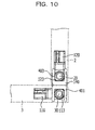
- FIG. 10 is a side view of the linking portion in a 90-degree opened state.
- FIG. 11 is a side view of the linking portion in a 135-degree opened state.
- FIG. 12 is a side view of the linking portion in a 180-degree opened state.
- the upper casing 2 and the lower casing 3 in each state are represented by dashed lines.
- the stopper 113 of the linking member 110 abuts a wall 401 of the housing 140.
- the linking member 110 is restricted from rotating from this state in the direction approaching the linking member 120.
- a stopper 123 of the linking member 120 abuts a wall 402 of the housing 140.
- the linking member 120 is restricted from rotating from this state in the direction approaching the linking member 110.
- the upper casing 2 and the lower casing 3 are opened, because the load torque of the linking member 110 is larger than the load torque of the linking member 120, first, the linking member 110 does not rotate, and the linking member 120 starts to rotate.
- the linking member 120 when the linking member 120 further rotates 45 degrees from the state in FIG. 8 , the state in FIG. 9 is reached.
- the linking member 120 In the rotation from the state in FIG. 8 to the state in FIG. 9 , due to the rotation of the cams 121 and 122, the linking member 120 is made to gradually move in the direction in which the rotation axis 20 of the linking member 120 moves away from the rotation axis 30 of the linking member 110.
- the rotation axis 20 of the linking member 120 and the rotation axis 30 of the linking member 110 are farthest away from each other.
- the distance between the upper casing 2 and the lower casing 3 increases, and the linking member 120 rotates without the edge section 22 of the upper casing 2 interfering with the screen 31 of the lower casing 3.
- the upper casing 2 and the lower casing 3 are further opened from this state, because the load torque of the linking member 110 is still larger than the load torque of the linking member 120, the linking member 110 does not rotate, and the linking member 120 rotates further.
- the linking member 120 rotates 45 degrees from the state in FIG. 9 , the state in FIG. 10 is reached.
- the linking member 120 is made to move in the direction in which the rotation axis 20 of the linking member 120 approaches the rotation axis 30 of the linking member 110.
- the distance between the rotation axis 20 of the linking member 120 and the rotation axis 30 of the linking member 110 in the state in FIG. 10 is the same distance as in the closed state.
- the stopper 123 of the linking member 120 abuts a wall 403 of the housing 140.
- the linking member 120 is restricted from rotating from this state in the direction of further opening.
- the linking member 120 which has a large load torque starts to rotate.
- the linking member 110 rotates 45 degrees from the state in FIG. 10
- the state in FIG. 11 is reached.
- the linking member 110 is made to move in the direction in which the rotation axis 30 of the linking member 110 moves away from the rotation axis 20 of the linking member 120.
- the rotation axis 30 of the linking member 110 and the rotation axis 20 of the linking member 120 are farthest away from each other.
- the distance between the upper casing 2 and the lower casing 3 increases, and the linking member 110 rotates without the edge section 32 of the lower casing 3 interfering with the surface 23 of the upper casing 2.
- the linking member 110 when the linking member 110 further rotates 45 degrees from the state in FIG. 11 , the state in FIG. 12 is reached.
- the linking member 110 In the rotation from the state in FIG. 11 to the state in FIG. 12 , due to the cams 111 and 112 rotating and the restoring force produced by the M-shaped spring 130 (not depicted), the linking member 110 is made to gradually move in the direction in which the rotation axis 30 of the linking member 110 approaches the rotation axis 20 of the linking member 120.
- the distance between the rotation axis 30 of the linking member 110 and the rotation axis 20 of the linking member 120 in the state in FIG. 10 is the same distance as in the closed state.
- the stopper 113 of the linking member 110 abuts a wall 404 of the housing 140
- the stopper 123 of the linking member 120 abuts the wall 403 of the housing 140.
- FIG. 13 is a cross-sectional view of the linking portion in the closed state.
- FIG. 14 is a cross-sectional view of the linking portion in a 45-degree opened state.
- FIG. 15 is a cross-sectional view of the linking portion in a 90-degree opened state.
- FIG. 16 is a cross-sectional view of the linking portion in a 135-degree opened state.
- FIG. 17 is a cross-sectional view of the linking portion in a 180-degree opened state.
- FIG. 13 to FIG. 17 depict the cross section corresponding to the A-A cross section in FIG. 5 in each of the states.
- the upper casing 2 and the lower casing 3 in each state are represented by dashed lines.
- the cam crest of the cam 111 is the cam crest 510.
- the cam crest of the cam 121 is the cam crest 520.
- the cam crest 510 of the cam 111 is in a position away from the cam receiver 149 of the housing 140.
- the cam crest 520 of the cam 121 is in a position away from the cam receiver 150 of the housing 140.
- a force is applied to the cylindrical member 116 and the cylindrical member 126 by the M-shaped spring 130 in the direction in which the rotation axis 20 and the rotation axis 30 become closer. Consequently, in this instance, a state is reached in which the rotation axis 20 and the rotation axis 30 are closest.
- the distance L2 from the rotation axis 20 to the screen 31 of the lower casing 3 is greater than the distance L1 from the rotation axis 20 to the edge section 22.
- This state is the state in which the upper casing 2 is closest to the lower casing 3 in the rotation of the linking member 120, and by ensuring that in this state the edge section 22 does not come into contact with the screen 31 of the lower casing 3, it is possible for the upper casing 2 to rotate without interfering with the lower casing 3. Furthermore, during this process, because the load torque of the cam 111 is larger than the load torque of the cam 121, a state is maintained in which the cam crest 510 abuts the cam receiver 149, and the linking member 110 stops and does not rotate.
- the state in FIG. 16 is reached.
- the cam crest 510 rides up the cam receiver 149, and the linking member 110 is made to gradually move in the direction in which the rotation axis 30 of the linking member 110 moves away from the rotation axis 20 of the linking member 120.
- the distance between the linking member 110 and the linking member 120 is the largest.
- the distance L4 from the rotation axis 30 to the screen 21 of the upper casing 2 is greater than the distance L3 from the rotation axis 30 to the edge section 32.
- This state is the state in which the lower casing 3 is closest to the upper casing 2 in the rotation of the linking member 110, and by ensuring that in this state the edge section 32 does not come into contact with the surface 23 of the upper casing 2, it is possible for the lower casing 3 to rotate without interfering with the upper casing 2.
- the state in FIG. 17 is reached. Due to the rotation from the state in FIG. 16 to the state in FIG. 17 , the cam crest 510 of the cam 111 comes away from the cam receiver 149. Thus, due to the restoring force produced by the M-shaped spring 130, the linking member 110 is made to move in the direction in which the rotation axis 30 of the linking member 110 approaches the rotation axis 20 of the linking member 120. The distance between the rotation axis 30 of the linking member 110 and the rotation axis 20 of the linking member 120 in the state in FIG. 17 is the same distance as when the upper casing 2 and the lower casing 3 are closed. In addition, the state in FIG.
- the stopper 113 of the linking member 110 abuts the wall 404 of the housing 140
- the stopper 123 of the linking member 120 abuts the wall 403 of the housing 140. Therefore, the upper casing 2 and the lower casing 3 are restricted from rotating from this state in the direction of further opening. In other words, the linking member 110 and the linking member 120 do not open any further.
- the state in FIG. 15 is reached. Due to the rotation from the state in FIG. 16 to the state in FIG. 15 , the cam crest 510 of the cam 111 comes away from the cam receiver 149. Thus, due to the restoring force produced by the M-shaped spring 130, the linking member 110 is made to move in the direction in which the rotation axis 30 of the linking member 110 approaches the rotation axis 20 of the linking member 120. The distance between the rotation axis 20 of the linking member 120 and the rotation axis 30 of the linking member 110 in the state in FIG. 15 is the same distance as when the upper casing 2 and the lower casing 3 have closed.
- the state in FIG. 13 is reached. Due to the rotation from the state in FIG. 14 to the state in FIG. 13 , the cam crest 520 of the cam 121 comes away from the cam receiver 150. Thus, due to the restoring force produced by the M-shaped spring 130, the linking member 120 is made to move in the direction in which the rotation axis 20 of the linking member 120 approaches the rotation axis 30 of the linking member 110.
- the distance between the rotation axis 30 of the linking member 110 and the rotation axis 20 of the linking member 120 in the state in FIG. 13 is the same distance as when the upper casing 2 and the lower casing 3 have closed.
- an M-shaped spring is used as a member that shortens the distance between the linking member 110 and the linking member 120 that have been moved apart by the cams
- another member may be used here as long as the member applies a force to the linking member 110 and the linking member 120 in the direction in which the rotation axis 20 and the rotation axis 30 become closer.
- an elastic body such as a coil spring or the like may be arranged between the linking member 110 and the linking member 120.
- a member that presses the linking member 110 toward the linking member 120 from the side opposite the linking member 120, and a member that presses the linking member 120 toward the linking member 110 from the side opposite the linking member 110 may be arranged.
- the load torques of the cam 111, the cam 112, the cam 121, and the cam 122 are adjusted so that the linking member 110 and the linking member 120 rotate in sequence. If the sequence in which the linking member 110 and the linking member 120 rotate is not set by altering the load torques, there is a risk that the cam at the lower casing 3 side of the hinge 1B will move at the same time as when the cam at the upper casing 2 side of the hinge 1A moves, for example. In this instance, there is a risk of the casings twisting, and opening and closing becoming difficult or the casings and the hinges being damaged.
- the linking member 110 and the linking member 120 rotate in sequence as in the present embodiment, it is possible to ensure ease of opening and closing, and to reduce damage to the casings and the hinges.
- the casings and the hinges have high rigidity and if it is certain that an operator will perform opening and closing in a careful manner and so on, the load torques of the cam 111, the cam 112, the cam 121, and the cam 122 do not have to be differed.
- the load torques of the cam 111, the cam 112, the cam 121, and the cam 122 are adjusted such that the upper casing 2 opens first during opening, and the lower casing 3 closes first during closing.
- the load torques of the cams may be adjusted such that the upper casing 2 rotates first at either the opening or the closing timing.
Landscapes
- Engineering & Computer Science (AREA)
- Signal Processing (AREA)
- Mechanical Engineering (AREA)
- Pivots And Pivotal Connections (AREA)
- Telephone Set Structure (AREA)
- Casings For Electric Apparatus (AREA)
- Transmission Devices (AREA)
Applications Claiming Priority (1)
| Application Number | Priority Date | Filing Date | Title |
|---|---|---|---|
| JP2013067665A JP6197327B2 (ja) | 2013-03-27 | 2013-03-27 | 電子機器 |
Publications (2)
| Publication Number | Publication Date |
|---|---|
| EP2797296A2 true EP2797296A2 (de) | 2014-10-29 |
| EP2797296A3 EP2797296A3 (de) | 2015-03-18 |
Family
ID=50189600
Family Applications (1)
| Application Number | Title | Priority Date | Filing Date |
|---|---|---|---|
| EP14157516.7A Withdrawn EP2797296A3 (de) | 2013-03-27 | 2014-03-03 | Elektronische Vorrichtung |
Country Status (4)
| Country | Link |
|---|---|
| US (1) | US9598886B2 (de) |
| EP (1) | EP2797296A3 (de) |
| JP (1) | JP6197327B2 (de) |
| CN (1) | CN104080288B (de) |
Cited By (9)
| Publication number | Priority date | Publication date | Assignee | Title |
|---|---|---|---|---|
| WO2017087343A1 (en) * | 2015-11-20 | 2017-05-26 | Microsoft Technology Licensing, Llc | Hinged device |
| US10241548B2 (en) | 2016-12-09 | 2019-03-26 | Microsoft Technology Licensing, Llc | Computing device employing a self-spacing hinge assembly |
| US10253804B2 (en) | 2017-01-24 | 2019-04-09 | Microsoft Technology Licensing, Llc | Hinged device |
| US10296044B2 (en) | 2017-06-08 | 2019-05-21 | Microsoft Technology Licensing, Llc | Hinged device |
| US10344510B2 (en) | 2017-06-16 | 2019-07-09 | Microsoft Technology Licensing, Llc | Hinged device |
| US10364598B2 (en) | 2016-09-02 | 2019-07-30 | Microsoft Technology Licensing, Llc | Hinged device |
| US10474203B2 (en) | 2016-09-01 | 2019-11-12 | Microsoft Technology Licensing, Llc | Hinged device |
| US10641318B2 (en) | 2016-12-09 | 2020-05-05 | Microsoft Technology Licensing, Llc | Hinged device |
| CN115337656A (zh) * | 2022-09-15 | 2022-11-15 | 上海布鲁可积木科技有限公司 | 玩具门转动结构及太空舱玩具 |
Families Citing this family (35)
| Publication number | Priority date | Publication date | Assignee | Title |
|---|---|---|---|---|
| CN104930048A (zh) * | 2014-03-17 | 2015-09-23 | 联想(北京)有限公司 | 一种双轴铰链及电子设备 |
| CN104284542A (zh) * | 2014-10-24 | 2015-01-14 | 成都中远信电子科技有限公司 | 带展开式支架的电子装置 |
| CN104329549A (zh) * | 2014-10-27 | 2015-02-04 | 成都中远信电子科技有限公司 | 立式支撑架 |
| CN104270917A (zh) * | 2014-10-28 | 2015-01-07 | 成都中远信电子科技有限公司 | 带立式支架的电子装置 |
| US9625954B2 (en) | 2014-11-26 | 2017-04-18 | Microsoft Technology Licensing, Llc | Multi-pivot hinge |
| US10174534B2 (en) | 2015-01-27 | 2019-01-08 | Microsoft Technology Licensing, Llc | Multi-pivot hinge |
| US10162389B2 (en) | 2015-09-25 | 2018-12-25 | Microsoft Technology Licensing, Llc | Covered multi-axis hinge |
| US10501973B2 (en) * | 2016-06-14 | 2019-12-10 | Microsoft Technology Licensing, Llc | Hinge with free-stop function |
| US10301858B2 (en) * | 2016-06-14 | 2019-05-28 | Microsoft Technology Licensing, Llc | Hinge mechanism |
| US10437293B2 (en) | 2016-09-23 | 2019-10-08 | Microsoft Technology Licensing, Llc | Multi-axis hinge |
| EP3526655B1 (de) * | 2017-02-06 | 2021-04-28 | Hewlett-Packard Development Company, L.P. | Achsenverschiebbare scharnieranordnungen |
| US10088875B1 (en) * | 2017-07-10 | 2018-10-02 | Leohab Enterprises Co., Ltd. | 360° pivotal device for an electronic product |
| CN110324441B (zh) * | 2018-03-30 | 2021-03-09 | Oppo广东移动通信有限公司 | 移动终端 |
| TWI695665B (zh) * | 2018-06-21 | 2020-06-01 | 仁寶電腦工業股份有限公司 | 鉸鏈模組及電子裝置 |
| USD928135S1 (en) * | 2018-12-21 | 2021-08-17 | Samsung Electronics Co., Ltd. | Case for mobile phone |
| US11116300B2 (en) * | 2019-01-18 | 2021-09-14 | Case-Mate, Inc. | Tension spring assisted protective cover |
| US11647819B2 (en) | 2019-01-18 | 2023-05-16 | Case-Mate, Inc. | Tension spring assisted protective cover |
| USD879084S1 (en) * | 2019-02-25 | 2020-03-24 | Spigen Korea Co., Ltd. | Case for electronic communications device |
| USD877136S1 (en) * | 2019-02-25 | 2020-03-03 | Spigen Korea Co., Ltd. | Case for electronic communications device |
| USD879764S1 (en) * | 2019-02-27 | 2020-03-31 | Spigen Korea Co., Ltd. | Case for electronic communications device |
| CN109992054B (zh) * | 2019-03-30 | 2021-04-13 | 联想(北京)有限公司 | 一种电子设备、连接装置 |
| CN109857201B (zh) * | 2019-03-31 | 2024-09-17 | 联想(北京)有限公司 | 一种电子设备、连接装置 |
| USD905675S1 (en) * | 2019-06-25 | 2020-12-22 | Spigen Korea Co., Ltd. | Case for electronic communications device |
| CN113357257B (zh) * | 2020-03-03 | 2022-05-10 | 英业达科技有限公司 | 转轴结构 |
| USD910004S1 (en) * | 2020-03-20 | 2021-02-09 | Spigen Korea Co., Ltd. | Case for electronic communications device |
| USD902934S1 (en) * | 2020-07-10 | 2020-11-24 | Pioneer Square Brands, Inc. | Case for portable electronic computing device |
| USD999198S1 (en) * | 2020-07-22 | 2023-09-19 | Spigen Korea Co., Ltd. | Case for electronic communications device |
| USD999199S1 (en) * | 2020-07-22 | 2023-09-19 | Spigen Korea Co., Ltd. | Case for electronic communications device |
| USD1001113S1 (en) * | 2020-07-22 | 2023-10-10 | Spigen Korea Co., Ltd. | Case for electronic communications device |
| USD999200S1 (en) * | 2020-07-22 | 2023-09-19 | Spigen Korea Co., Ltd. | Case for electronic communications device |
| CN114333566B (zh) * | 2020-09-30 | 2025-01-10 | 华为技术有限公司 | 一种折叠装置及电子设备 |
| KR20220159111A (ko) | 2021-05-25 | 2022-12-02 | 삼성전자주식회사 | 폴더블 전자 장치 |
| WO2023017946A1 (ko) * | 2021-08-09 | 2023-02-16 | 삼성전자 주식회사 | 힌지 구조 및 이를 포함하는 폴더블 전자 장치 |
| CN116291082B (zh) * | 2023-04-04 | 2025-10-31 | 奇点变幻科技(天津)有限公司 | 一种可360度旋转的铰链结构 |
| WO2025005394A1 (ko) * | 2023-06-26 | 2025-01-02 | 삼성전자주식회사 | 힌지 어셈블리 및 이를 포함하는 전자 장치 |
Citations (2)
| Publication number | Priority date | Publication date | Assignee | Title |
|---|---|---|---|---|
| JP2006228812A (ja) | 2005-02-15 | 2006-08-31 | Toshiba Corp | 電子機器 |
| JP2010250463A (ja) | 2009-04-14 | 2010-11-04 | Sony Corp | 情報処理装置、情報処理方法及びプログラム |
Family Cites Families (23)
| Publication number | Priority date | Publication date | Assignee | Title |
|---|---|---|---|---|
| US3191218A (en) * | 1963-12-03 | 1965-06-29 | Stanley M Skiba | Hinge structures with multiple pintles |
| US6253419B1 (en) * | 2000-01-13 | 2001-07-03 | Lu Sheng-Nan | Pivot device with multiple pivotal bars for a notebook computer |
| EP1264230A2 (de) | 2000-01-24 | 2002-12-11 | Spotware Technologies, Inc. | Kompaktbarer / konvertienbarer modularer pda |
| US7032984B2 (en) | 2000-08-09 | 2006-04-25 | Si Han Kim | Case for portable display devices |
| JP2006144892A (ja) * | 2004-11-18 | 2006-06-08 | Kantatsu Co Ltd | 折り畳み式携帯電話機 |
| JP4729545B2 (ja) | 2007-09-13 | 2011-07-20 | 京セラ株式会社 | 携帯通信端末機 |
| JP5112121B2 (ja) * | 2008-03-13 | 2013-01-09 | 加藤電機株式会社 | 2軸ヒンジ装置並びに電子機器 |
| JP2013007392A (ja) * | 2009-10-20 | 2013-01-10 | Panasonic Corp | 携帯端末装置 |
| CN102109005B (zh) * | 2009-12-25 | 2013-10-09 | 鸿富锦精密工业(深圳)有限公司 | 铰链结构及使用该铰链结构的电子装置 |
| KR101062621B1 (ko) | 2010-01-29 | 2011-09-07 | 주식회사 케이에이치바텍 | 이중 회전축을 갖는 힌지모듈이 구비된 휴대단말기 |
| US20110265288A1 (en) * | 2010-04-29 | 2011-11-03 | Yung-Chang Chiang | Two-stage dual-pintle hinge |
| US8660621B2 (en) | 2010-08-20 | 2014-02-25 | Blackberry Limited | Mobile phone |
| US20120137471A1 (en) * | 2010-12-03 | 2012-06-07 | Nokia Corporation | Hinge Apparatus and Method |
| JP5039216B2 (ja) * | 2011-02-24 | 2012-10-03 | 株式会社東芝 | 電子機器 |
| JP2012237392A (ja) * | 2011-05-12 | 2012-12-06 | Katoh Electrical Machinery Co Ltd | 平行2軸ヒンジ並びにこの平行2軸ヒンジを備えた小型電子機器 |
| KR101237952B1 (ko) | 2011-05-19 | 2013-02-28 | (주) 프렉코 | 힌지장치 및 이를 구비한 휴대용 전자장치 |
| JP5801607B2 (ja) * | 2011-05-31 | 2015-10-28 | スタッフ株式会社 | 電子機器 |
| TWM422001U (en) * | 2011-07-13 | 2012-02-01 | Quanta Comp Inc | Dual-axis hinge structure and electric device having the same |
| JP6079630B2 (ja) * | 2011-09-21 | 2017-02-15 | 日本電気株式会社 | 電子機器 |
| US9201464B2 (en) * | 2011-11-28 | 2015-12-01 | Lenovo (Beijing) Co., Ltd. | Terminal apparatus |
| CN103140093B (zh) * | 2011-11-29 | 2016-08-17 | 富泰华工业(深圳)有限公司 | 电子装置 |
| US20130170108A1 (en) * | 2012-01-04 | 2013-07-04 | Le-Yao Lin | Hinge and electronic device with the hinge |
| TWM466285U (zh) * | 2013-03-27 | 2013-11-21 | First Dome Corp | 雙軸式轉軸樞轉定位結構 |
-
2013
- 2013-03-27 JP JP2013067665A patent/JP6197327B2/ja not_active Expired - Fee Related
-
2014
- 2014-02-25 US US14/189,484 patent/US9598886B2/en not_active Expired - Fee Related
- 2014-03-03 EP EP14157516.7A patent/EP2797296A3/de not_active Withdrawn
- 2014-03-13 CN CN201410092496.XA patent/CN104080288B/zh active Active
Patent Citations (2)
| Publication number | Priority date | Publication date | Assignee | Title |
|---|---|---|---|---|
| JP2006228812A (ja) | 2005-02-15 | 2006-08-31 | Toshiba Corp | 電子機器 |
| JP2010250463A (ja) | 2009-04-14 | 2010-11-04 | Sony Corp | 情報処理装置、情報処理方法及びプログラム |
Cited By (10)
| Publication number | Priority date | Publication date | Assignee | Title |
|---|---|---|---|---|
| WO2017087343A1 (en) * | 2015-11-20 | 2017-05-26 | Microsoft Technology Licensing, Llc | Hinged device |
| US10227808B2 (en) | 2015-11-20 | 2019-03-12 | Microsoft Technology Licensing, Llc | Hinged device |
| US10474203B2 (en) | 2016-09-01 | 2019-11-12 | Microsoft Technology Licensing, Llc | Hinged device |
| US10364598B2 (en) | 2016-09-02 | 2019-07-30 | Microsoft Technology Licensing, Llc | Hinged device |
| US10241548B2 (en) | 2016-12-09 | 2019-03-26 | Microsoft Technology Licensing, Llc | Computing device employing a self-spacing hinge assembly |
| US10641318B2 (en) | 2016-12-09 | 2020-05-05 | Microsoft Technology Licensing, Llc | Hinged device |
| US10253804B2 (en) | 2017-01-24 | 2019-04-09 | Microsoft Technology Licensing, Llc | Hinged device |
| US10296044B2 (en) | 2017-06-08 | 2019-05-21 | Microsoft Technology Licensing, Llc | Hinged device |
| US10344510B2 (en) | 2017-06-16 | 2019-07-09 | Microsoft Technology Licensing, Llc | Hinged device |
| CN115337656A (zh) * | 2022-09-15 | 2022-11-15 | 上海布鲁可积木科技有限公司 | 玩具门转动结构及太空舱玩具 |
Also Published As
| Publication number | Publication date |
|---|---|
| JP2014192398A (ja) | 2014-10-06 |
| JP6197327B2 (ja) | 2017-09-20 |
| US20140290009A1 (en) | 2014-10-02 |
| CN104080288A (zh) | 2014-10-01 |
| EP2797296A3 (de) | 2015-03-18 |
| CN104080288B (zh) | 2017-09-08 |
| US9598886B2 (en) | 2017-03-21 |
Similar Documents
| Publication | Publication Date | Title |
|---|---|---|
| US9598886B2 (en) | Electronic device | |
| US11846997B2 (en) | Rotating shaft mechanism and mobile terminal | |
| EP4354834B1 (de) | Klappmechanismus und elektronische vorrichtung | |
| KR102114080B1 (ko) | 폴딩 힌지 장치 및 이를 구비하는 전자기기 | |
| CN100435607C (zh) | 铰链装置和使用该铰链装置的电子设备 | |
| US20180066465A1 (en) | Hinged device | |
| KR100600614B1 (ko) | 휴대단말기용 힌지 | |
| KR20200054258A (ko) | 내부 플렉서블 스크린 모바일 단말기의 힌지 및 내부 플렉서블 스크린 모바일 단말기 | |
| KR101142836B1 (ko) | 2축 힌지 모듈 및 이것이 장착된 휴대단말기 | |
| US11622457B2 (en) | Synchronous transmission pivot shaft device | |
| US11561588B2 (en) | Pivot shaft structure moving around virtual axis | |
| CN108398986A (zh) | 电子装置及其铰链组件 | |
| KR20240056572A (ko) | 회전 샤프트 메커니즘 및 전자 장치 | |
| CN115030951B (zh) | 铰链、柔性显示面板及显示终端 | |
| US20060085947A1 (en) | Hinge and a mobile phone with the hinge | |
| KR100547726B1 (ko) | 휴대용 무선 단말기 폴더의 회전 멈춤 장치 | |
| JP2009068550A (ja) | 折り畳み式携帯電子機器のヒンジ構造 | |
| JP5348690B2 (ja) | スライド回転ヒンジ、及び携帯機器 | |
| CN117366095A (zh) | 铰链机构和电子设备 | |
| CN211599256U (zh) | 转轴链组结构 | |
| CN118855844B (zh) | 铰链机构和电子设备 | |
| EP4520984B1 (de) | Scharniermechanismus und elektronische vorrichtung | |
| CN214465525U (zh) | 连接装置及电子设备 | |
| TWM547232U (zh) | 樞紐器以及使用該樞紐器的電子裝置 | |
| KR101045543B1 (ko) | 스윙 힌지장치 및 이를 구비하는 전자기기 |
Legal Events
| Date | Code | Title | Description |
|---|---|---|---|
| PUAI | Public reference made under article 153(3) epc to a published international application that has entered the european phase |
Free format text: ORIGINAL CODE: 0009012 |
|
| 17P | Request for examination filed |
Effective date: 20140303 |
|
| AK | Designated contracting states |
Kind code of ref document: A2 Designated state(s): AL AT BE BG CH CY CZ DE DK EE ES FI FR GB GR HR HU IE IS IT LI LT LU LV MC MK MT NL NO PL PT RO RS SE SI SK SM TR |
|
| AX | Request for extension of the european patent |
Extension state: BA ME |
|
| PUAL | Search report despatched |
Free format text: ORIGINAL CODE: 0009013 |
|
| AK | Designated contracting states |
Kind code of ref document: A3 Designated state(s): AL AT BE BG CH CY CZ DE DK EE ES FI FR GB GR HR HU IE IS IT LI LT LU LV MC MK MT NL NO PL PT RO RS SE SI SK SM TR |
|
| AX | Request for extension of the european patent |
Extension state: BA ME |
|
| RIC1 | Information provided on ipc code assigned before grant |
Ipc: E05D 3/12 20060101ALI20150212BHEP Ipc: H04M 1/02 20060101AFI20150212BHEP |
|
| R17P | Request for examination filed (corrected) |
Effective date: 20150716 |
|
| RBV | Designated contracting states (corrected) |
Designated state(s): AL AT BE BG CH CY CZ DE DK EE ES FI FR GB GR HR HU IE IS IT LI LT LU LV MC MK MT NL NO PL PT RO RS SE SI SK SM TR |
|
| 17Q | First examination report despatched |
Effective date: 20160209 |
|
| STAA | Information on the status of an ep patent application or granted ep patent |
Free format text: STATUS: THE APPLICATION IS DEEMED TO BE WITHDRAWN |
|
| 18D | Application deemed to be withdrawn |
Effective date: 20171003 |