EP2796648A2 - Verschluss für einen Treibstangenbeschlag - Google Patents
Verschluss für einen Treibstangenbeschlag Download PDFInfo
- Publication number
- EP2796648A2 EP2796648A2 EP14161489.1A EP14161489A EP2796648A2 EP 2796648 A2 EP2796648 A2 EP 2796648A2 EP 14161489 A EP14161489 A EP 14161489A EP 2796648 A2 EP2796648 A2 EP 2796648A2
- Authority
- EP
- European Patent Office
- Prior art keywords
- locking
- edge
- sleeve
- closure
- striking plate
- Prior art date
- Legal status (The legal status is an assumption and is not a legal conclusion. Google has not performed a legal analysis and makes no representation as to the accuracy of the status listed.)
- Granted
Links
Images
Classifications
-
- E—FIXED CONSTRUCTIONS
- E05—LOCKS; KEYS; WINDOW OR DOOR FITTINGS; SAFES
- E05C—BOLTS OR FASTENING DEVICES FOR WINGS, SPECIALLY FOR DOORS OR WINDOWS
- E05C9/00—Arrangements of simultaneously actuated bolts or other securing devices at well-separated positions on the same wing
- E05C9/18—Details of fastening means or of fixed retaining means for the ends of bars
- E05C9/1825—Fastening means
- E05C9/1833—Fastening means performing sliding movements
- E05C9/185—Fastening means performing sliding movements parallel with actuating bar
- E05C9/1858—Fastening means performing sliding movements parallel with actuating bar of the roller bolt type
-
- E—FIXED CONSTRUCTIONS
- E05—LOCKS; KEYS; WINDOW OR DOOR FITTINGS; SAFES
- E05B—LOCKS; ACCESSORIES THEREFOR; HANDCUFFS
- E05B17/00—Accessories in connection with locks
- E05B17/007—Devices for reducing friction between lock parts
-
- E—FIXED CONSTRUCTIONS
- E05—LOCKS; KEYS; WINDOW OR DOOR FITTINGS; SAFES
- E05C—BOLTS OR FASTENING DEVICES FOR WINGS, SPECIALLY FOR DOORS OR WINDOWS
- E05C9/00—Arrangements of simultaneously actuated bolts or other securing devices at well-separated positions on the same wing
- E05C9/18—Details of fastening means or of fixed retaining means for the ends of bars
- E05C9/1808—Keepers
Definitions
- the invention relates to a closure for a driving rod fitting with a striking plate and with a behind a locking edge of the striker movable locking pin, wherein the locking pin has a fixed core member and a rotatable sleeve disposed on the core member.
- Such a closure is for example from the DE 101 10 632 A1 known.
- the sleeve is designed as a roller.
- the lateral surface of the sleeve is moved over the locking edge of the striking plate.
- trained as a roller sleeve can rotate. This limits the introduction of torque into the fixed core element.
- the closure is smooth.
- a disadvantage of this closure is that even a small out-of-roundness of the trained as a sleeve roller causes it blocked and no longer rolls on the locking edge. As a result, the sleeve remains in its rotational position and complicates the operation of the closure.
- a locking pin has become known in which the sleeve is designed as a rotatable or pivotal inlet aid.
- the inlet aid can have the form of a toothed wheel.
- a disadvantage of this locking pin is that the inlet aid exclusively at the initial movement of the locking pin against an inlet edge of the striking plate can be effective. During the movement along the locking pin along the locking edge, the inlet aid is pressed against the blocking edge with two teeth and prevents it from twisting. The operation of the closure equipped with this lock is therefore particularly uncomfortable.
- the DE 27 51 813 C2 discloses a closure in which on a core element, a cylinder jacket-like sheath made of wear-resistant material is arranged. During the movement of the locking pin along the locking edge, however, sliding friction occurs at all times. The operation of this closure is therefore very difficult.
- the invention is based on the problem to form a closure of the aforementioned type so that it is particularly easy to operate.
- the interlocking elements ensure by their interlocking design that the sleeve is securely rotated during movement along the locking edge.
- the sleeve of the locking pin thus rolls on the locking edge. This prevents sliding friction.
- the closure of the invention is therefore particularly easy to operate.
- the rotation of the sleeve when moving along the locking edge is carried out according to another advantageous embodiment of the invention with a particularly high reliability when the positive locking elements are formed as arranged on the sleeve and the locking edge teeth.
- the form-locking elements formed analogous to a compound of a gear with a rack.
- the toothing of the sleeve preferably extends over the entire circumference. The toothing is aligned transversely to the direction of movement of the sleeve.
- the lock pin designed in accordance with another advantageous embodiment of the invention structurally particularly simple when the sleeve is mounted axially immovable on the core member and a circumferential, the locking edge engages behind, diameter-sized edge and a subsequent to the edge, small diameter sheath and if the interlocking elements are arranged exclusively on the mantle.
- the production of the closure is particularly cost-effective according to another advantageous embodiment of the invention, when the locking edge or the locking edge opposite portion of the sleeve made of high-strength steel and the respective opposing component is made of a soft material compared to the high-strength steel.
- the form-locking elements in the production can be produced, for example, exclusively in the blocking edge.
- the corresponding form-fitting elements of the sleeve are impressed during operation of the closure of the form-locking elements of the locking edge.
- the closure can be inexpensively used both for right-hand and for left-hinged windows if the striking plate has two locking edges arranged symmetrically to one another and if the positive-locking elements are arranged on both locking edges.
- the positive-locking elements are also arranged on the blocking edges which are not required for the respective window.
- the strike plate can thereby be manufactured inexpensively in mass production regardless of the stop side of the window.
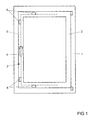
- FIG. 1 shows a window with a pivotable against a frame 1 wing 2.
- the window has a drive rod fitting 3 with a driven by a handle 4 drive rod 5.
- About the closures 6, the wing 2 can optionally lock or release in the frame 1.
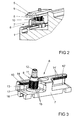
- FIG. 2 shows in perspective a portion of the window FIG. 1 in the area of one of the closures 6.
- the wing 2 is made FIG. 1 not shown.
- the shutter 6 has a fixed in the frame 1 strike plate 7 and one on the drive rod 5 fixed locking pin 8.
- the drive rod 5 is guided longitudinally displaceable on a fixed to the wing 2 faceplate 9.
- the locking pin 8 engages behind a locking edge 10 of the striking plate. 7
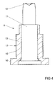
- FIG. 3 shows in perspective the components of the closure 6 FIG. 2 , It can be seen that the locking pin 8 is a core element 11 with a rivet head 12 for riveting with in the FIGS. 1 and 2 illustrated drive rod 5 has. On the core member 11, a sleeve 13 is rotatably mounted. The locking edge 10 and a jacket 17 of the sleeve 13 each have interlocking toothing form-fitting elements 14, 15. During a movement of the locking pin 8 by means of drive over in the FIGS. 1 and 2 illustrated drive rod 5 along the locking edge 10, the sleeve 13 is rotated relative to the core element 11.
- the locking pin 7 has at its free end also a circumferential, the locking edge 10 engaging behind edge 16. Furthermore, in FIG.
- the striking plate 7 has a second locking edge 10 'also designed as a toothing form-locking elements 14'.
- This second blocking edge 10 ' is arranged symmetrically to the first blocking edge 10, so that the closure 6 is suitable for the optional arrangement in left and right-hinged windows.
- FIG. 4 shows for clarity a sectional view of the sleeve 13 of the closure 6. It can be seen that the sleeve 13 is arranged axially immovably on the core element 11. The edge 16 has a larger diameter than the jacket 17th
Landscapes
- Engineering & Computer Science (AREA)
- Mechanical Engineering (AREA)
- Lock And Its Accessories (AREA)
- Slide Fasteners (AREA)
Abstract
Description
- Die Erfindung betrifft einen Verschluss für einen Treibstangenbeschlag mit einem Schließblech und mit einem hinter eine Sperrkante des Schließblechs bewegbaren Schließzapfen, wobei der Schließzapfen ein feststehendes Kernelement und eine auf dem Kernelement angeordnete drehbare Hülse hat.
- Ein solcher Verschluss ist beispielsweise aus der
DE 101 10 632 A1 bekannt. Bei diesem Verschluss ist die Hülse als Laufrolle ausgebildet. Beim Schließen des Verschlusses wird die Mantelfläche der Hülse über die Sperrkante des Schließblechs bewegt. Dabei kann sich die als Laufrolle ausgebildete Hülse drehen. Dies begrenzt die Einleitung eines Drehmoments in das feststehende Kernelement. Weiterhin ist der Verschluss leichtgängig. Nachteilig bei diesem Verschluss ist jedoch, dass bereits eine geringe Unrundheit der als Hülse ausgebildeten Laufrolle dazu führt, dass diese blockiert und nicht mehr an der Sperrkante abrollt. In der Folge verharrt die Hülse in ihrer Drehstellung und erschwert die Betätigung des Verschlusses. - Weiterhin ist aus der
DE 20 2007 010 048 U1 ein Schließzapfen bekannt geworden, bei welchem die Hülse als drehbare oder schwenkbare Einlaufhilfe ausgebildet ist. Die Einlaufhilfe kann die Form eines Zahnrades aufweisen. Nachteilig bei diesem Schließzapfen ist jedoch, dass die Einlaufhilfe ausschließlich bei der anfänglichen Bewegung des Schließzapfens gegen eine Einlaufkante des Schließblechs wirksam sein kann. Bei der Entlangbewegung des Schließzapfens entlang der Sperrkante wird die Einlaufhilfe mit zwei Zähnen gegen die Sperrkante gedrückt und verhindert ein Verdrehen. Die Betätigung des mit diesem Schließzapfen ausgestatteten Verschlusses gestaltet sich daher besonders unkomfortabel. - Die
DE 27 51 813 C2 offenbart einen Verschluss, bei dem auf einem Kernelement eine zylindermantelartige Umhüllung aus verschleißfestem Werkstoff angeordnet ist. Bei der Bewegung des Schließzapfens entlang der Sperrkante entsteht jedoch jederzeit Gleitreibung. Die Betätigung dieses Verschlusses ist daher sehr schwergängig. - Der Erfindung liegt das Problem zugrunde, einen Verschluss der eingangs genannten Art so weiter zu bilden, dass er besonders leichtgängig zu betätigen ist.
- Dieses Problem wird erfindungsgemäß dadurch gelöst, dass die Hülse und die Sperrkante ineinandergreifende Formschlusselemente aufweisen.
- Hierdurch stellen die Formschlusselemente durch ihre ineinandergreifende Gestaltung sicher, dass die Hülse bei der Bewegung entlang der Sperrkante sicher gedreht wird. Die Hülse des Schließzapfens rollt sich damit auf der Sperrkante ab. Damit wird eine Gleitreibung vermieden. Der erfindungsgemäße Verschluss ist daher besonders leichtgängig zu betätigen.
- Die Drehung der Hülse beim Bewegen entlang der Sperrkante erfolgt gemäß einer anderen vorteilhaften Weiterbildung der Erfindung mit einer besonders hohen Zuverlässigkeit, wenn die Formschlusselemente als auf der Hülse und der Sperrkante angeordnete Verzahnung ausgebildet sind. Durch diese Gestaltung sind die Formschlusselemente analog einer Verbindung eines Zahnrades mit einer Zahnstange gebildet. Die Verzahnung der Hülse erstreckt sich vorzugsweise über den gesamten Umfang. Die Verzahnung ist quer zur Bewegungsrichtung der Hülse ausgerichtet.
- Der Schließzapfen gestaltet sich gemäß einer anderen vorteilhaften Weiterbildung der Erfindung konstruktiv besonders einfach, wenn die Hülse axial unverschieblich auf dem Kernelement gelagert ist und einen umlaufenden, die Sperrkante hintergreifenden, durchmessergroßen Rand und einen sich an den Rand anschließenden, durchmesserkleinen Mantel hat und wenn die Formschlusselemente ausschließlich auf dem Mantel angeordnet sind.
- Die Fertigung des Verschlusses gestaltet sich gemäß einer anderen vorteilhaften Weiterbildung der Erfindung besonders kostengünstig, wenn die Sperrkante oder der der Sperrkante gegenüberstehende Abschnitt der Hülse aus hochfestem Stahl und das jeweils gegenüberstehende Bauteil aus einem im Vergleich zum hochfesten Stahl weichen Material gefertigt ist. Durch diese Gestaltung können die Formschlusselemente in der Fertigung beispielsweise ausschließlich in der Sperrkante erzeugt sein. Die entsprechenden Formschlusselemente der Hülse werden beim Betrieb des Verschlusses von den Formschlusselementen der Sperrkante eingeprägt.
- Der Verschluss lässt sich gemäß einer anderen vorteilhaften Weiterbildung der Erfindung kostengünstig sowohl für rechts- als auch für linksanschlagende Fenster einsetzbar, wenn das Schließblech zwei symmetrisch zueinander angeordnete Sperrkanten hat und wenn die Formschlusselemente auf beiden Sperrkanten angeordnet sind. Durch diese Gestaltung sind die Formschlusselemente auch auf den bei dem jeweiligen Fenster nicht benötigten Sperrkanten angeordnet. Jedoch lässt sich das Schließblech hierdurch in Großserie unabhängig von der Anschlagseite des Fensters kostengünstig fertigen.
- Die Erfindung lässt zahlreiche Ausführungsformen zu. Zur weiteren Verdeutlichung ihres Grundprinzips ist eine davon in der Zeichnung dargestellt und wird nachfolgend beschrieben. Diese zeigt in
- Fig. 1
- ein Fenster mit einem erfindungsgemäßen Verschluss,
- Fig. 2
- vergrößert eine perspektivische Darstellung des Verschlusses aus
Figur 1 mit angrenzenden Bereichen des Fensters, - Fig. 3
- perspektivisch die Bauteile des Verschlusses aus
Figur 1 , - Fig. 4
- stark vergrößert eine Schnittdarstellung eines Schließzapfens des erfindungsgemäßen Verschlusses aus
Figur 1 . -
Figur 1 zeigt ein Fenster mit einem gegen einen Rahmen 1 schwenkbaren Flügel 2. Das Fenster hat einen Treibstangenbeschlag 3 mit einer von einer Handhabe 4 antreibbaren Treibstange 5. Über die Treibstange 5 werden auf dem Umfang des Flügels 2 verteilt angeordnete Verschlüsse 6 angesteuert. Über die Verschlüsse 6 lässt sich der Flügel 2 wahlweise in dem Rahmen 1 verriegeln oder freigeben. -
Figur 2 zeigt perspektivisch einen Teilbereich des Fensters ausFigur 1 im Bereich einer der Verschlüsse 6. Zur Vereinfachung der Zeichnung ist der Flügel 2 ausFigur 1 nicht dargestellt. Der Verschluss 6 hat ein im Rahmen 1 befestigtes Schließblech 7 und einen auf der Treibstange 5 befestigten Schließzapfen 8. Die Treibstange 5 ist an einer an dem Flügel 2 befestigten Stulpschiene 9 längsverschieblich geführt. In der dargestellten, verriegelten Stellung des Verschlusses 6 hintergreift der Schließzapfen 8 eine Sperrkante 10 des Schließblechs 7. -
Figur 3 zeigt perspektivisch die Bauteile des Verschlusses 6 ausFigur 2 . Hierbei ist zu erkennen, dass der Schließzapfen 8 ein Kernelement 11 mit einem Nietkopf 12 zur Vernietung mit der in denFiguren 1 und2 dargestellten Treibstange 5 hat. Auf dem Kernelement 11 ist eine Hülse 13 drehbar gelagert. Die Sperrkante 10 und ein Mantel 17 der Hülse 13 weisen jeweils als ineinandergreifende Verzahnung ausgebildete Formschlusselemente 14, 15 auf. Bei einer Bewegung des Schließzapfens 8 mittels Antrieb über die in denFiguren 1 und2 dargestellte Treibstange 5 entlang der Sperrkante 10 wird die Hülse 13 gegenüber dem Kernelement 11 verdreht. Der Schließzapfen 7 hat an seinem freien Ende zudem einen umlaufenden, die Sperrkante 10 hintergreifenden Rand 16. Weiterhin ist inFigur 3 zu erkennen, dass das Schließblech 7 eine zweite Sperrkante 10' ebenfalls mit als Verzahnung ausgebildeten Formschlusselementen 14' hat. Diese zweite Sperrkante 10' ist symmetrisch zur ersten Sperrkante 10 angeordnet, so dass der Verschluss 6 zur wahlweisen Anordnung in links-und rechtsanschlagenden Fenstern geeignet ist. -
Figur 4 zeigt zur Verdeutlichung eine Schnittdarstellung der Hülse 13 des Verschlusses 6. Hierbei ist zu erkennen, dass die Hülse 13 axial unverschieblich auf dem Kernelement 11 angeordnet ist. Der Rand 16 hat einen größeren Durchmesser als der Mantel 17.
Claims (5)
- Verschluss (6) für einen Treibstangenbeschlag (3) mit einem Schließblech (7) und mit einem hinter eine Sperrkante (10) des Schließblechs (7) bewegbaren Schließzapfen (8), wobei der Schließzapfen (8) ein feststehendes Kernelement (11) und eine auf dem Kernelement (11) angeordnete drehbare Hülse (13) hat, dadurch gekennzeichnet, dass die Hülse (13) und die Sperrkante (10) ineinandergreifende Formschlusselemente (14, 15) aufweisen.
- Verschluss nach Anspruch 1, dadurch gekennzeichnet, dass die Formschlusselemente (14, 15) als auf der Hülse (13) und der Sperrkante (10) angeordnete Verzahnung ausgebildet sind.
- Verschluss nach Anspruch 1 oder 2, dadurch gekennzeichnet, dass die Hülse (13) axial unverschieblich auf dem Kernelement (11) gelagert ist und einen umlaufenden, die Sperrkante (10) hintergreifenden durchmessergroßen Rand (16) und einen sich an den Rand (16) anschließenden durchmesserkleinen Mantel (17) hat und dass die Formschlusselemente (14, 15) ausschließlich auf dem Mantel (17) angeordnet sind.
- Verschluss nach einem der Ansprüche 1 bis 3, dadurch gekennzeichnet, dass die Sperrkante (10) oder der der Sperrkante (10) gegenüberstehende Abschnitt der Hülse (13) aus hochfestem Stahl und das jeweils gegenüberstehende Bauteil aus einem im Vergleich zum hochfesten Stahl weichen Material gefertigt ist.
- Verschluss nach einem der Ansprüche 1 bis 4, dadurch gekennzeichnet, dass das Schließblech (7) zwei symmetrisch zueinander angeordnete Sperrkanten (10, 10') hat und dass die Formschlusselemente (14, 14') auf beiden Sperrkanten (10, 10') angeordnet sind.
Priority Applications (1)
| Application Number | Priority Date | Filing Date | Title |
|---|---|---|---|
| PL14161489T PL2796648T3 (pl) | 2013-04-26 | 2014-03-25 | Zamknięcie dla okucia zasuwnicy |
Applications Claiming Priority (1)
| Application Number | Priority Date | Filing Date | Title |
|---|---|---|---|
| DE102013207674.6A DE102013207674A1 (de) | 2013-04-26 | 2013-04-26 | Verschluss für einen Treibstangenbeschlag |
Publications (3)
| Publication Number | Publication Date |
|---|---|
| EP2796648A2 true EP2796648A2 (de) | 2014-10-29 |
| EP2796648A3 EP2796648A3 (de) | 2015-11-25 |
| EP2796648B1 EP2796648B1 (de) | 2017-05-10 |
Family
ID=50345933
Family Applications (1)
| Application Number | Title | Priority Date | Filing Date |
|---|---|---|---|
| EP14161489.1A Active EP2796648B1 (de) | 2013-04-26 | 2014-03-25 | Verschluss für einen Treibstangenbeschlag |
Country Status (3)
| Country | Link |
|---|---|
| EP (1) | EP2796648B1 (de) |
| DE (1) | DE102013207674A1 (de) |
| PL (1) | PL2796648T3 (de) |
Citations (3)
| Publication number | Priority date | Publication date | Assignee | Title |
|---|---|---|---|---|
| DE2751813C2 (de) | 1977-11-19 | 1986-12-11 | Siegenia-Frank Kg, 5900 Siegen | Flügelverschluß für Fenster, Türen od.dgl. |
| DE10110632A1 (de) | 2000-03-17 | 2001-09-20 | Schuering Gmbh & Co Fenster Te | Verriegelungsvorrichtung mit pilzförmigem Zapfen |
| DE202007010048U1 (de) | 2007-07-19 | 2007-09-20 | Roto Frank Ag | Fenster, Tür o.dgl. mit einem Schließstück |
Family Cites Families (1)
| Publication number | Priority date | Publication date | Assignee | Title |
|---|---|---|---|---|
| DE102006035416B4 (de) * | 2006-11-09 | 2014-11-27 | Aug. Winkhaus Gmbh & Co. Kg | Verschluss für einen Treibstangenbeschlag |
-
2013
- 2013-04-26 DE DE102013207674.6A patent/DE102013207674A1/de not_active Withdrawn
-
2014
- 2014-03-25 EP EP14161489.1A patent/EP2796648B1/de active Active
- 2014-03-25 PL PL14161489T patent/PL2796648T3/pl unknown
Patent Citations (3)
| Publication number | Priority date | Publication date | Assignee | Title |
|---|---|---|---|---|
| DE2751813C2 (de) | 1977-11-19 | 1986-12-11 | Siegenia-Frank Kg, 5900 Siegen | Flügelverschluß für Fenster, Türen od.dgl. |
| DE10110632A1 (de) | 2000-03-17 | 2001-09-20 | Schuering Gmbh & Co Fenster Te | Verriegelungsvorrichtung mit pilzförmigem Zapfen |
| DE202007010048U1 (de) | 2007-07-19 | 2007-09-20 | Roto Frank Ag | Fenster, Tür o.dgl. mit einem Schließstück |
Also Published As
| Publication number | Publication date |
|---|---|
| PL2796648T3 (pl) | 2017-10-31 |
| EP2796648A3 (de) | 2015-11-25 |
| DE102013207674A1 (de) | 2014-10-30 |
| EP2796648B1 (de) | 2017-05-10 |
Similar Documents
| Publication | Publication Date | Title |
|---|---|---|
| EP2058461B1 (de) | Treibstangengetriebe | |
| DE102019125148A1 (de) | Nebenschloss für eine Mehrpunktverriegelung | |
| DE202008003555U1 (de) | Rollenbolzen | |
| EP3034728B1 (de) | Öffnungsbegrenzereinrichtung | |
| DE2459695B2 (de) | Zylinderschloßbetatigbarer Schubriegelantrieb für Türen o.dgl | |
| EP3091151B1 (de) | Treibstangensperre für einen treibstangenbeschlag | |
| EP2796648B1 (de) | Verschluss für einen Treibstangenbeschlag | |
| EP3194690B1 (de) | Beschlag für fenster, türen oder dergleichen | |
| DE102008016319B4 (de) | Schloss mit einer Sicherheitseinrichtung | |
| AT508560B1 (de) | Verriegelungszapfen | |
| EP2735678A2 (de) | Beschlag für Fenster, Türen oder dergleichen | |
| EP1683938B1 (de) | Verschluss für einen Treibstangenbeschlag | |
| DE202011002661U1 (de) | Sicherheitsschloss | |
| AT519509A2 (de) | Türschloss | |
| EP2320013B1 (de) | Beschlag mit einem Umkehrgetriebe | |
| EP3450664B1 (de) | Verriegelungsanordnung für einen flügel | |
| EP3061896B1 (de) | Beschlaganordnung | |
| DE2531727A1 (de) | Schliessvorrichtung | |
| DE102010032145B4 (de) | Torverriegelungsvorrichtung sowie Überkopftor umfassend eine Torverriegelungsvorrichtung | |
| EP3655605B1 (de) | Schloss | |
| DE19736934A1 (de) | Verriegelungsbeschlag | |
| AT406176B (de) | Mehrriegelverschluss | |
| EP2808472B1 (de) | Beschlag sowie Fenster, Tür oder dergleichen mit Beschlag und Verfahren zum Verriegeln | |
| EP2855809B1 (de) | Beschlagsystem für ein fenster, eine tür oder dergleichen | |
| DE1934007C (de) | Fur Fenster, Türen od dgl bestimmter Zentralverschluß |
Legal Events
| Date | Code | Title | Description |
|---|---|---|---|
| PUAI | Public reference made under article 153(3) epc to a published international application that has entered the european phase |
Free format text: ORIGINAL CODE: 0009012 |
|
| 17P | Request for examination filed |
Effective date: 20140325 |
|
| AK | Designated contracting states |
Kind code of ref document: A2 Designated state(s): AL AT BE BG CH CY CZ DE DK EE ES FI FR GB GR HR HU IE IS IT LI LT LU LV MC MK MT NL NO PL PT RO RS SE SI SK SM TR |
|
| AX | Request for extension of the european patent |
Extension state: BA ME |
|
| PUAL | Search report despatched |
Free format text: ORIGINAL CODE: 0009013 |
|
| AK | Designated contracting states |
Kind code of ref document: A3 Designated state(s): AL AT BE BG CH CY CZ DE DK EE ES FI FR GB GR HR HU IE IS IT LI LT LU LV MC MK MT NL NO PL PT RO RS SE SI SK SM TR |
|
| AX | Request for extension of the european patent |
Extension state: BA ME |
|
| RIC1 | Information provided on ipc code assigned before grant |
Ipc: E05C 9/18 20060101AFI20151019BHEP Ipc: E05B 15/02 20060101ALI20151019BHEP |
|
| R17P | Request for examination filed (corrected) |
Effective date: 20160330 |
|
| RBV | Designated contracting states (corrected) |
Designated state(s): AL AT BE BG CH CY CZ DE DK EE ES FI FR GB GR HR HU IE IS IT LI LT LU LV MC MK MT NL NO PL PT RO RS SE SI SK SM TR |
|
| GRAP | Despatch of communication of intention to grant a patent |
Free format text: ORIGINAL CODE: EPIDOSNIGR1 |
|
| INTG | Intention to grant announced |
Effective date: 20161206 |
|
| GRAS | Grant fee paid |
Free format text: ORIGINAL CODE: EPIDOSNIGR3 |
|
| GRAA | (expected) grant |
Free format text: ORIGINAL CODE: 0009210 |
|
| AK | Designated contracting states |
Kind code of ref document: B1 Designated state(s): AL AT BE BG CH CY CZ DE DK EE ES FI FR GB GR HR HU IE IS IT LI LT LU LV MC MK MT NL NO PL PT RO RS SE SI SK SM TR |
|
| REG | Reference to a national code |
Ref country code: GB Ref legal event code: FG4D Free format text: NOT ENGLISH |
|
| REG | Reference to a national code |
Ref country code: AT Ref legal event code: REF Ref document number: 892505 Country of ref document: AT Kind code of ref document: T Effective date: 20170515 Ref country code: CH Ref legal event code: EP |
|
| REG | Reference to a national code |
Ref country code: IE Ref legal event code: FG4D Free format text: LANGUAGE OF EP DOCUMENT: GERMAN |
|
| REG | Reference to a national code |
Ref country code: DE Ref legal event code: R096 Ref document number: 502014003718 Country of ref document: DE |
|
| REG | Reference to a national code |
Ref country code: SE Ref legal event code: TRGR |
|
| REG | Reference to a national code |
Ref country code: NL Ref legal event code: MP Effective date: 20170510 |
|
| REG | Reference to a national code |
Ref country code: LT Ref legal event code: MG4D |
|
| PG25 | Lapsed in a contracting state [announced via postgrant information from national office to epo] |
Ref country code: NO Free format text: LAPSE BECAUSE OF FAILURE TO SUBMIT A TRANSLATION OF THE DESCRIPTION OR TO PAY THE FEE WITHIN THE PRESCRIBED TIME-LIMIT Effective date: 20170810 Ref country code: ES Free format text: LAPSE BECAUSE OF FAILURE TO SUBMIT A TRANSLATION OF THE DESCRIPTION OR TO PAY THE FEE WITHIN THE PRESCRIBED TIME-LIMIT Effective date: 20170510 Ref country code: LT Free format text: LAPSE BECAUSE OF FAILURE TO SUBMIT A TRANSLATION OF THE DESCRIPTION OR TO PAY THE FEE WITHIN THE PRESCRIBED TIME-LIMIT Effective date: 20170510 Ref country code: GR Free format text: LAPSE BECAUSE OF FAILURE TO SUBMIT A TRANSLATION OF THE DESCRIPTION OR TO PAY THE FEE WITHIN THE PRESCRIBED TIME-LIMIT Effective date: 20170811 Ref country code: HR Free format text: LAPSE BECAUSE OF FAILURE TO SUBMIT A TRANSLATION OF THE DESCRIPTION OR TO PAY THE FEE WITHIN THE PRESCRIBED TIME-LIMIT Effective date: 20170510 Ref country code: FI Free format text: LAPSE BECAUSE OF FAILURE TO SUBMIT A TRANSLATION OF THE DESCRIPTION OR TO PAY THE FEE WITHIN THE PRESCRIBED TIME-LIMIT Effective date: 20170510 |
|
| PG25 | Lapsed in a contracting state [announced via postgrant information from national office to epo] |
Ref country code: BG Free format text: LAPSE BECAUSE OF FAILURE TO SUBMIT A TRANSLATION OF THE DESCRIPTION OR TO PAY THE FEE WITHIN THE PRESCRIBED TIME-LIMIT Effective date: 20170810 Ref country code: LV Free format text: LAPSE BECAUSE OF FAILURE TO SUBMIT A TRANSLATION OF THE DESCRIPTION OR TO PAY THE FEE WITHIN THE PRESCRIBED TIME-LIMIT Effective date: 20170510 Ref country code: RS Free format text: LAPSE BECAUSE OF FAILURE TO SUBMIT A TRANSLATION OF THE DESCRIPTION OR TO PAY THE FEE WITHIN THE PRESCRIBED TIME-LIMIT Effective date: 20170510 Ref country code: NL Free format text: LAPSE BECAUSE OF FAILURE TO SUBMIT A TRANSLATION OF THE DESCRIPTION OR TO PAY THE FEE WITHIN THE PRESCRIBED TIME-LIMIT Effective date: 20170510 Ref country code: IS Free format text: LAPSE BECAUSE OF FAILURE TO SUBMIT A TRANSLATION OF THE DESCRIPTION OR TO PAY THE FEE WITHIN THE PRESCRIBED TIME-LIMIT Effective date: 20170910 |
|
| PG25 | Lapsed in a contracting state [announced via postgrant information from national office to epo] |
Ref country code: EE Free format text: LAPSE BECAUSE OF FAILURE TO SUBMIT A TRANSLATION OF THE DESCRIPTION OR TO PAY THE FEE WITHIN THE PRESCRIBED TIME-LIMIT Effective date: 20170510 Ref country code: CZ Free format text: LAPSE BECAUSE OF FAILURE TO SUBMIT A TRANSLATION OF THE DESCRIPTION OR TO PAY THE FEE WITHIN THE PRESCRIBED TIME-LIMIT Effective date: 20170510 Ref country code: DK Free format text: LAPSE BECAUSE OF FAILURE TO SUBMIT A TRANSLATION OF THE DESCRIPTION OR TO PAY THE FEE WITHIN THE PRESCRIBED TIME-LIMIT Effective date: 20170510 Ref country code: RO Free format text: LAPSE BECAUSE OF FAILURE TO SUBMIT A TRANSLATION OF THE DESCRIPTION OR TO PAY THE FEE WITHIN THE PRESCRIBED TIME-LIMIT Effective date: 20170510 Ref country code: SK Free format text: LAPSE BECAUSE OF FAILURE TO SUBMIT A TRANSLATION OF THE DESCRIPTION OR TO PAY THE FEE WITHIN THE PRESCRIBED TIME-LIMIT Effective date: 20170510 |
|
| REG | Reference to a national code |
Ref country code: DE Ref legal event code: R097 Ref document number: 502014003718 Country of ref document: DE |
|
| PG25 | Lapsed in a contracting state [announced via postgrant information from national office to epo] |
Ref country code: SM Free format text: LAPSE BECAUSE OF FAILURE TO SUBMIT A TRANSLATION OF THE DESCRIPTION OR TO PAY THE FEE WITHIN THE PRESCRIBED TIME-LIMIT Effective date: 20170510 |
|
| PLBE | No opposition filed within time limit |
Free format text: ORIGINAL CODE: 0009261 |
|
| STAA | Information on the status of an ep patent application or granted ep patent |
Free format text: STATUS: NO OPPOSITION FILED WITHIN TIME LIMIT |
|
| REG | Reference to a national code |
Ref country code: FR Ref legal event code: PLFP Year of fee payment: 5 |
|
| 26N | No opposition filed |
Effective date: 20180213 |
|
| PG25 | Lapsed in a contracting state [announced via postgrant information from national office to epo] |
Ref country code: SI Free format text: LAPSE BECAUSE OF FAILURE TO SUBMIT A TRANSLATION OF THE DESCRIPTION OR TO PAY THE FEE WITHIN THE PRESCRIBED TIME-LIMIT Effective date: 20170510 |
|
| PG25 | Lapsed in a contracting state [announced via postgrant information from national office to epo] |
Ref country code: MT Free format text: LAPSE BECAUSE OF FAILURE TO SUBMIT A TRANSLATION OF THE DESCRIPTION OR TO PAY THE FEE WITHIN THE PRESCRIBED TIME-LIMIT Effective date: 20170510 |
|
| REG | Reference to a national code |
Ref country code: CH Ref legal event code: PL |
|
| PG25 | Lapsed in a contracting state [announced via postgrant information from national office to epo] |
Ref country code: MC Free format text: LAPSE BECAUSE OF FAILURE TO SUBMIT A TRANSLATION OF THE DESCRIPTION OR TO PAY THE FEE WITHIN THE PRESCRIBED TIME-LIMIT Effective date: 20170510 |
|
| REG | Reference to a national code |
Ref country code: IE Ref legal event code: MM4A |
|
| PG25 | Lapsed in a contracting state [announced via postgrant information from national office to epo] |
Ref country code: LU Free format text: LAPSE BECAUSE OF NON-PAYMENT OF DUE FEES Effective date: 20180325 |
|
| PG25 | Lapsed in a contracting state [announced via postgrant information from national office to epo] |
Ref country code: IE Free format text: LAPSE BECAUSE OF NON-PAYMENT OF DUE FEES Effective date: 20180325 |
|
| PG25 | Lapsed in a contracting state [announced via postgrant information from national office to epo] |
Ref country code: LI Free format text: LAPSE BECAUSE OF NON-PAYMENT OF DUE FEES Effective date: 20180331 Ref country code: CH Free format text: LAPSE BECAUSE OF NON-PAYMENT OF DUE FEES Effective date: 20180331 |
|
| PG25 | Lapsed in a contracting state [announced via postgrant information from national office to epo] |
Ref country code: HU Free format text: LAPSE BECAUSE OF FAILURE TO SUBMIT A TRANSLATION OF THE DESCRIPTION OR TO PAY THE FEE WITHIN THE PRESCRIBED TIME-LIMIT; INVALID AB INITIO Effective date: 20140325 Ref country code: PT Free format text: LAPSE BECAUSE OF FAILURE TO SUBMIT A TRANSLATION OF THE DESCRIPTION OR TO PAY THE FEE WITHIN THE PRESCRIBED TIME-LIMIT Effective date: 20170510 |
|
| PG25 | Lapsed in a contracting state [announced via postgrant information from national office to epo] |
Ref country code: MK Free format text: LAPSE BECAUSE OF NON-PAYMENT OF DUE FEES Effective date: 20170510 Ref country code: CY Free format text: LAPSE BECAUSE OF FAILURE TO SUBMIT A TRANSLATION OF THE DESCRIPTION OR TO PAY THE FEE WITHIN THE PRESCRIBED TIME-LIMIT Effective date: 20170510 |
|
| PG25 | Lapsed in a contracting state [announced via postgrant information from national office to epo] |
Ref country code: AL Free format text: LAPSE BECAUSE OF FAILURE TO SUBMIT A TRANSLATION OF THE DESCRIPTION OR TO PAY THE FEE WITHIN THE PRESCRIBED TIME-LIMIT Effective date: 20170510 |
|
| PGFP | Annual fee paid to national office [announced via postgrant information from national office to epo] |
Ref country code: GB Payment date: 20220324 Year of fee payment: 9 |
|
| PGFP | Annual fee paid to national office [announced via postgrant information from national office to epo] |
Ref country code: TR Payment date: 20220315 Year of fee payment: 9 Ref country code: SE Payment date: 20220324 Year of fee payment: 9 Ref country code: PL Payment date: 20220314 Year of fee payment: 9 |
|
| PGFP | Annual fee paid to national office [announced via postgrant information from national office to epo] |
Ref country code: FR Payment date: 20230320 Year of fee payment: 10 |
|
| PGFP | Annual fee paid to national office [announced via postgrant information from national office to epo] |
Ref country code: BE Payment date: 20230321 Year of fee payment: 10 |
|
| P01 | Opt-out of the competence of the unified patent court (upc) registered |
Effective date: 20230515 |
|
| PGFP | Annual fee paid to national office [announced via postgrant information from national office to epo] |
Ref country code: IT Payment date: 20230331 Year of fee payment: 10 |
|
| REG | Reference to a national code |
Ref country code: SE Ref legal event code: EUG |
|
| GBPC | Gb: european patent ceased through non-payment of renewal fee |
Effective date: 20230325 |
|
| PG25 | Lapsed in a contracting state [announced via postgrant information from national office to epo] |
Ref country code: GB Free format text: LAPSE BECAUSE OF NON-PAYMENT OF DUE FEES Effective date: 20230325 |
|
| PG25 | Lapsed in a contracting state [announced via postgrant information from national office to epo] |
Ref country code: SE Free format text: LAPSE BECAUSE OF NON-PAYMENT OF DUE FEES Effective date: 20230326 Ref country code: GB Free format text: LAPSE BECAUSE OF NON-PAYMENT OF DUE FEES Effective date: 20230325 |
|
| PGFP | Annual fee paid to national office [announced via postgrant information from national office to epo] |
Ref country code: AT Payment date: 20240318 Year of fee payment: 11 |
|
| PGFP | Annual fee paid to national office [announced via postgrant information from national office to epo] |
Ref country code: DE Payment date: 20240321 Year of fee payment: 11 |
|
| PG25 | Lapsed in a contracting state [announced via postgrant information from national office to epo] |
Ref country code: PL Free format text: LAPSE BECAUSE OF NON-PAYMENT OF DUE FEES Effective date: 20230325 |
|
| PG25 | Lapsed in a contracting state [announced via postgrant information from national office to epo] |
Ref country code: PL Free format text: LAPSE BECAUSE OF NON-PAYMENT OF DUE FEES Effective date: 20230325 |
|
| REG | Reference to a national code |
Ref country code: DE Ref legal event code: R081 Ref document number: 502014003718 Country of ref document: DE Owner name: AUG. WINKHAUS SE & CO. KG, DE Free format text: FORMER OWNER: AUG. WINKHAUS GMBH & CO. KG, 48291 TELGTE, DE Ref country code: DE Ref legal event code: R081 Ref document number: 502014003718 Country of ref document: DE Owner name: AUG. WINKHAUS SE, DE Free format text: FORMER OWNER: AUG. WINKHAUS GMBH & CO. KG, 48291 TELGTE, DE |
|
| REG | Reference to a national code |
Ref country code: BE Ref legal event code: MM Effective date: 20240331 |
|
| PG25 | Lapsed in a contracting state [announced via postgrant information from national office to epo] |
Ref country code: BE Free format text: LAPSE BECAUSE OF NON-PAYMENT OF DUE FEES Effective date: 20240331 |
|
| PG25 | Lapsed in a contracting state [announced via postgrant information from national office to epo] |
Ref country code: FR Free format text: LAPSE BECAUSE OF NON-PAYMENT OF DUE FEES Effective date: 20240331 |
|
| PG25 | Lapsed in a contracting state [announced via postgrant information from national office to epo] |
Ref country code: FR Free format text: LAPSE BECAUSE OF NON-PAYMENT OF DUE FEES Effective date: 20240331 Ref country code: BE Free format text: LAPSE BECAUSE OF NON-PAYMENT OF DUE FEES Effective date: 20240331 |
|
| PG25 | Lapsed in a contracting state [announced via postgrant information from national office to epo] |
Ref country code: IT Free format text: LAPSE BECAUSE OF NON-PAYMENT OF DUE FEES Effective date: 20240325 |
|
| REG | Reference to a national code |
Ref country code: DE Ref legal event code: R081 Ref document number: 502014003718 Country of ref document: DE Owner name: AUG. WINKHAUS SE, DE Free format text: FORMER OWNER: AUG. WINKHAUS SE & CO. KG, 48291 TELGTE, DE |
|
| REG | Reference to a national code |
Ref country code: DE Ref legal event code: R119 Ref document number: 502014003718 Country of ref document: DE |
|
| REG | Reference to a national code |
Ref country code: AT Ref legal event code: MM01 Ref document number: 892505 Country of ref document: AT Kind code of ref document: T Effective date: 20250325 |
|
| PG25 | Lapsed in a contracting state [announced via postgrant information from national office to epo] |
Ref country code: DE Free format text: LAPSE BECAUSE OF NON-PAYMENT OF DUE FEES Effective date: 20251001 |
|
| PG25 | Lapsed in a contracting state [announced via postgrant information from national office to epo] |
Ref country code: AT Free format text: LAPSE BECAUSE OF NON-PAYMENT OF DUE FEES Effective date: 20250325 |