EP2796351B1 - Saddled electric vehicle - Google Patents
Saddled electric vehicle Download PDFInfo
- Publication number
- EP2796351B1 EP2796351B1 EP12858988.4A EP12858988A EP2796351B1 EP 2796351 B1 EP2796351 B1 EP 2796351B1 EP 12858988 A EP12858988 A EP 12858988A EP 2796351 B1 EP2796351 B1 EP 2796351B1
- Authority
- EP
- European Patent Office
- Prior art keywords
- receptacle
- plug
- gun
- vehicle
- type
- Prior art date
- Legal status (The legal status is an assumption and is not a legal conclusion. Google has not performed a legal analysis and makes no representation as to the accuracy of the status listed.)
- Active
Links
Images





Classifications
-
- B—PERFORMING OPERATIONS; TRANSPORTING
- B62—LAND VEHICLES FOR TRAVELLING OTHERWISE THAN ON RAILS
- B62M—RIDER PROPULSION OF WHEELED VEHICLES OR SLEDGES; POWERED PROPULSION OF SLEDGES OR SINGLE-TRACK CYCLES; TRANSMISSIONS SPECIALLY ADAPTED FOR SUCH VEHICLES
- B62M7/00—Motorcycles characterised by position of motor or engine
- B62M7/12—Motorcycles characterised by position of motor or engine with the engine beside or within the driven wheel
-
- B—PERFORMING OPERATIONS; TRANSPORTING
- B60—VEHICLES IN GENERAL
- B60K—ARRANGEMENT OR MOUNTING OF PROPULSION UNITS OR OF TRANSMISSIONS IN VEHICLES; ARRANGEMENT OR MOUNTING OF PLURAL DIVERSE PRIME-MOVERS IN VEHICLES; AUXILIARY DRIVES FOR VEHICLES; INSTRUMENTATION OR DASHBOARDS FOR VEHICLES; ARRANGEMENTS IN CONNECTION WITH COOLING, AIR INTAKE, GAS EXHAUST OR FUEL SUPPLY OF PROPULSION UNITS IN VEHICLES
- B60K7/00—Disposition of motor in, or adjacent to, traction wheel
- B60K7/0007—Disposition of motor in, or adjacent to, traction wheel the motor being electric
-
- B—PERFORMING OPERATIONS; TRANSPORTING
- B60—VEHICLES IN GENERAL
- B60L—PROPULSION OF ELECTRICALLY-PROPELLED VEHICLES; SUPPLYING ELECTRIC POWER FOR AUXILIARY EQUIPMENT OF ELECTRICALLY-PROPELLED VEHICLES; ELECTRODYNAMIC BRAKE SYSTEMS FOR VEHICLES IN GENERAL; MAGNETIC SUSPENSION OR LEVITATION FOR VEHICLES; MONITORING OPERATING VARIABLES OF ELECTRICALLY-PROPELLED VEHICLES; ELECTRIC SAFETY DEVICES FOR ELECTRICALLY-PROPELLED VEHICLES
- B60L50/00—Electric propulsion with power supplied within the vehicle
- B60L50/50—Electric propulsion with power supplied within the vehicle using propulsion power supplied by batteries or fuel cells
- B60L50/52—Electric propulsion with power supplied within the vehicle using propulsion power supplied by batteries or fuel cells characterised by DC-motors
-
- B—PERFORMING OPERATIONS; TRANSPORTING
- B60—VEHICLES IN GENERAL
- B60L—PROPULSION OF ELECTRICALLY-PROPELLED VEHICLES; SUPPLYING ELECTRIC POWER FOR AUXILIARY EQUIPMENT OF ELECTRICALLY-PROPELLED VEHICLES; ELECTRODYNAMIC BRAKE SYSTEMS FOR VEHICLES IN GENERAL; MAGNETIC SUSPENSION OR LEVITATION FOR VEHICLES; MONITORING OPERATING VARIABLES OF ELECTRICALLY-PROPELLED VEHICLES; ELECTRIC SAFETY DEVICES FOR ELECTRICALLY-PROPELLED VEHICLES
- B60L50/00—Electric propulsion with power supplied within the vehicle
- B60L50/50—Electric propulsion with power supplied within the vehicle using propulsion power supplied by batteries or fuel cells
- B60L50/60—Electric propulsion with power supplied within the vehicle using propulsion power supplied by batteries or fuel cells using power supplied by batteries
- B60L50/66—Arrangements of batteries
-
- B—PERFORMING OPERATIONS; TRANSPORTING
- B60—VEHICLES IN GENERAL
- B60L—PROPULSION OF ELECTRICALLY-PROPELLED VEHICLES; SUPPLYING ELECTRIC POWER FOR AUXILIARY EQUIPMENT OF ELECTRICALLY-PROPELLED VEHICLES; ELECTRODYNAMIC BRAKE SYSTEMS FOR VEHICLES IN GENERAL; MAGNETIC SUSPENSION OR LEVITATION FOR VEHICLES; MONITORING OPERATING VARIABLES OF ELECTRICALLY-PROPELLED VEHICLES; ELECTRIC SAFETY DEVICES FOR ELECTRICALLY-PROPELLED VEHICLES
- B60L53/00—Methods of charging batteries, specially adapted for electric vehicles; Charging stations or on-board charging equipment therefor; Exchange of energy storage elements in electric vehicles
- B60L53/10—Methods of charging batteries, specially adapted for electric vehicles; Charging stations or on-board charging equipment therefor; Exchange of energy storage elements in electric vehicles characterised by the energy transfer between the charging station and the vehicle
- B60L53/14—Conductive energy transfer
- B60L53/16—Connectors, e.g. plugs or sockets, specially adapted for charging electric vehicles
-
- B—PERFORMING OPERATIONS; TRANSPORTING
- B62—LAND VEHICLES FOR TRAVELLING OTHERWISE THAN ON RAILS
- B62J—CYCLE SADDLES OR SEATS; AUXILIARY DEVICES OR ACCESSORIES SPECIALLY ADAPTED TO CYCLES AND NOT OTHERWISE PROVIDED FOR, e.g. ARTICLE CARRIERS OR CYCLE PROTECTORS
- B62J23/00—Other protectors specially adapted for cycles
-
- B—PERFORMING OPERATIONS; TRANSPORTING
- B62—LAND VEHICLES FOR TRAVELLING OTHERWISE THAN ON RAILS
- B62K—CYCLES; CYCLE FRAMES; CYCLE STEERING DEVICES; RIDER-OPERATED TERMINAL CONTROLS SPECIALLY ADAPTED FOR CYCLES; CYCLE AXLE SUSPENSIONS; CYCLE SIDECARS, FORECARS, OR THE LIKE
- B62K11/00—Motorcycles, engine-assisted cycles or motor scooters with one or two wheels
- B62K11/02—Frames
- B62K11/10—Frames characterised by the engine being over or beside driven rear wheel
-
- B—PERFORMING OPERATIONS; TRANSPORTING
- B60—VEHICLES IN GENERAL
- B60L—PROPULSION OF ELECTRICALLY-PROPELLED VEHICLES; SUPPLYING ELECTRIC POWER FOR AUXILIARY EQUIPMENT OF ELECTRICALLY-PROPELLED VEHICLES; ELECTRODYNAMIC BRAKE SYSTEMS FOR VEHICLES IN GENERAL; MAGNETIC SUSPENSION OR LEVITATION FOR VEHICLES; MONITORING OPERATING VARIABLES OF ELECTRICALLY-PROPELLED VEHICLES; ELECTRIC SAFETY DEVICES FOR ELECTRICALLY-PROPELLED VEHICLES
- B60L2200/00—Type of vehicles
- B60L2200/12—Bikes
-
- B—PERFORMING OPERATIONS; TRANSPORTING
- B60—VEHICLES IN GENERAL
- B60L—PROPULSION OF ELECTRICALLY-PROPELLED VEHICLES; SUPPLYING ELECTRIC POWER FOR AUXILIARY EQUIPMENT OF ELECTRICALLY-PROPELLED VEHICLES; ELECTRODYNAMIC BRAKE SYSTEMS FOR VEHICLES IN GENERAL; MAGNETIC SUSPENSION OR LEVITATION FOR VEHICLES; MONITORING OPERATING VARIABLES OF ELECTRICALLY-PROPELLED VEHICLES; ELECTRIC SAFETY DEVICES FOR ELECTRICALLY-PROPELLED VEHICLES
- B60L2210/00—Converter types
- B60L2210/30—AC to DC converters
-
- B—PERFORMING OPERATIONS; TRANSPORTING
- B62—LAND VEHICLES FOR TRAVELLING OTHERWISE THAN ON RAILS
- B62J—CYCLE SADDLES OR SEATS; AUXILIARY DEVICES OR ACCESSORIES SPECIALLY ADAPTED TO CYCLES AND NOT OTHERWISE PROVIDED FOR, e.g. ARTICLE CARRIERS OR CYCLE PROTECTORS
- B62J9/00—Containers specially adapted for cycles, e.g. panniers or saddle bags
- B62J9/10—Containers specially adapted for cycles, e.g. panniers or saddle bags integrated with the cycle
- B62J9/12—Containers specially adapted for cycles, e.g. panniers or saddle bags integrated with the cycle in the fairing
-
- B—PERFORMING OPERATIONS; TRANSPORTING
- B62—LAND VEHICLES FOR TRAVELLING OTHERWISE THAN ON RAILS
- B62K—CYCLES; CYCLE FRAMES; CYCLE STEERING DEVICES; RIDER-OPERATED TERMINAL CONTROLS SPECIALLY ADAPTED FOR CYCLES; CYCLE AXLE SUSPENSIONS; CYCLE SIDECARS, FORECARS, OR THE LIKE
- B62K2202/00—Motorised scooters
-
- B—PERFORMING OPERATIONS; TRANSPORTING
- B62—LAND VEHICLES FOR TRAVELLING OTHERWISE THAN ON RAILS
- B62K—CYCLES; CYCLE FRAMES; CYCLE STEERING DEVICES; RIDER-OPERATED TERMINAL CONTROLS SPECIALLY ADAPTED FOR CYCLES; CYCLE AXLE SUSPENSIONS; CYCLE SIDECARS, FORECARS, OR THE LIKE
- B62K2204/00—Adaptations for driving cycles by electric motor
-
- Y—GENERAL TAGGING OF NEW TECHNOLOGICAL DEVELOPMENTS; GENERAL TAGGING OF CROSS-SECTIONAL TECHNOLOGIES SPANNING OVER SEVERAL SECTIONS OF THE IPC; TECHNICAL SUBJECTS COVERED BY FORMER USPC CROSS-REFERENCE ART COLLECTIONS [XRACs] AND DIGESTS
- Y02—TECHNOLOGIES OR APPLICATIONS FOR MITIGATION OR ADAPTATION AGAINST CLIMATE CHANGE
- Y02T—CLIMATE CHANGE MITIGATION TECHNOLOGIES RELATED TO TRANSPORTATION
- Y02T10/00—Road transport of goods or passengers
- Y02T10/60—Other road transportation technologies with climate change mitigation effect
- Y02T10/70—Energy storage systems for electromobility, e.g. batteries
-
- Y—GENERAL TAGGING OF NEW TECHNOLOGICAL DEVELOPMENTS; GENERAL TAGGING OF CROSS-SECTIONAL TECHNOLOGIES SPANNING OVER SEVERAL SECTIONS OF THE IPC; TECHNICAL SUBJECTS COVERED BY FORMER USPC CROSS-REFERENCE ART COLLECTIONS [XRACs] AND DIGESTS
- Y02—TECHNOLOGIES OR APPLICATIONS FOR MITIGATION OR ADAPTATION AGAINST CLIMATE CHANGE
- Y02T—CLIMATE CHANGE MITIGATION TECHNOLOGIES RELATED TO TRANSPORTATION
- Y02T10/00—Road transport of goods or passengers
- Y02T10/60—Other road transportation technologies with climate change mitigation effect
- Y02T10/7072—Electromobility specific charging systems or methods for batteries, ultracapacitors, supercapacitors or double-layer capacitors
-
- Y—GENERAL TAGGING OF NEW TECHNOLOGICAL DEVELOPMENTS; GENERAL TAGGING OF CROSS-SECTIONAL TECHNOLOGIES SPANNING OVER SEVERAL SECTIONS OF THE IPC; TECHNICAL SUBJECTS COVERED BY FORMER USPC CROSS-REFERENCE ART COLLECTIONS [XRACs] AND DIGESTS
- Y02—TECHNOLOGIES OR APPLICATIONS FOR MITIGATION OR ADAPTATION AGAINST CLIMATE CHANGE
- Y02T—CLIMATE CHANGE MITIGATION TECHNOLOGIES RELATED TO TRANSPORTATION
- Y02T10/00—Road transport of goods or passengers
- Y02T10/60—Other road transportation technologies with climate change mitigation effect
- Y02T10/72—Electric energy management in electromobility
-
- Y—GENERAL TAGGING OF NEW TECHNOLOGICAL DEVELOPMENTS; GENERAL TAGGING OF CROSS-SECTIONAL TECHNOLOGIES SPANNING OVER SEVERAL SECTIONS OF THE IPC; TECHNICAL SUBJECTS COVERED BY FORMER USPC CROSS-REFERENCE ART COLLECTIONS [XRACs] AND DIGESTS
- Y02—TECHNOLOGIES OR APPLICATIONS FOR MITIGATION OR ADAPTATION AGAINST CLIMATE CHANGE
- Y02T—CLIMATE CHANGE MITIGATION TECHNOLOGIES RELATED TO TRANSPORTATION
- Y02T90/00—Enabling technologies or technologies with a potential or indirect contribution to GHG emissions mitigation
- Y02T90/10—Technologies relating to charging of electric vehicles
- Y02T90/12—Electric charging stations
-
- Y—GENERAL TAGGING OF NEW TECHNOLOGICAL DEVELOPMENTS; GENERAL TAGGING OF CROSS-SECTIONAL TECHNOLOGIES SPANNING OVER SEVERAL SECTIONS OF THE IPC; TECHNICAL SUBJECTS COVERED BY FORMER USPC CROSS-REFERENCE ART COLLECTIONS [XRACs] AND DIGESTS
- Y02—TECHNOLOGIES OR APPLICATIONS FOR MITIGATION OR ADAPTATION AGAINST CLIMATE CHANGE
- Y02T—CLIMATE CHANGE MITIGATION TECHNOLOGIES RELATED TO TRANSPORTATION
- Y02T90/00—Enabling technologies or technologies with a potential or indirect contribution to GHG emissions mitigation
- Y02T90/10—Technologies relating to charging of electric vehicles
- Y02T90/14—Plug-in electric vehicles
Definitions
- the present invention relates to a straddle-type electric vehicle according to the preamble of independent claim 1.
- a straddle-type electric vehicle can be taken from the prior art document EP 2 295 316 A2 .
- An electric motorcycle which uses an electric motor as a drive source includes a receptacle for charging a battery.
- a plug which is provided at an end portion of a cable which extends from a charger is connected with the receptacle.
- the charging station is provided with a gun-type plug having a plug portion to which the receptacle of the electric car is connected and a grip portion (for example, refer to Patent Literature 2).
- the gun-type plug is designed so that the gun-type plug is not connected with the receptacle unless a rotational position about an insertion/drawing direction of the plug matches predetermined position. Once the user grips the grip portion, the user can easily change a direction of the gun-type plug freely and easily match the mutual rotational positions. Further, after the rotational positions are matched each other, by putting the gun-type plug thereto, while leaving its posture as it is, the gun-type plug is electrically connected with the receptacle. Thus, the gun-type plug is easy to perform connecting work.
- the receptacle of the electric motorcycle is provided at a position lower than the receptacle of the electric car. Therefore, during charge, the charging plug is left in a state in which the plug is connected with the receptacle which is located at a lower position of the vehicle.
- the charging time is required more than 30 minutes, and the charging plug is located at the lower position, for an example, other vehicle which comes thereto overlooks the charging plug and contacts with the charging plug unintentionally.
- an object of the invention is to provide a straddle-type electric vehicle which is able to use the gun-type plug which is easy to perform connecting work and also suppresses influence on surrounding during charge to the utmost.
- a straddle-type electric vehicle including:
- the receptacle is provided in a position which is within a width of the leg shield in the left-and-right direction of the vehicle and between the leg shield and the rear wheel in the front-and-rear direction and is provided in a position facing the opening portion.
- the connection port faces upward.
- the receptacle is provided so that at least a part of the grip portion of the gun-type plug is, with respect to the vehicle, positioned leftward of the plug portion when the gun-type plug is connected with the receptacle.
- the gun-type plug having the plug portion and the grip portion is connectable with the receptacle.
- the opening portion to which the receptacle facing is provided in a space which is within the width of the leg shield in the left-and-right direction of the vehicle and between the leg shield and the rear wheel in the front-and-rear direction which is a space in which the occupant rest his/her foot normally.
- the work to connect the gun-type plug with the receptacle becomes easy and there is little fear that the other vehicle contacts with the plug during charge and thus, there is provided a straddle-type electric vehicle which suppresses an adverse influence on the surrounding.
- the receptacle is provided so that a grip portion of a gun-type plug extends obliquely with respect to left direction of the vehicle when a gun-type plug is connected with the receptacle.
- the grip portion does not extend leftward of the vehicle directly, but extends obliquely.
- the protrusion amount of the gun-type plug protruding sideward of the vehicle is further suppressed. Accordingly, it is further suppressed that the other vehicle contacts with the gun-type plug during charge.
- the receptacle is provided forward of the seat, and the receptacle is provided so that at least a part of a grip portion of a gun-type plug is, with respect to the vehicle, positioned rearward diagonal left of a plug portion of a gun-type plug when a gun-type plug is connected with the receptacle.
- the gun-type plug connected with the receptacle does not interfere with the seat.
- the straddle-type electric vehicle in which the connecting work of the gun-type plug to the receptacle is easy.
- the receptacle is provided rearward of the foot rest portion, and the receptacle is provided so that at least a part of a grip portion of a gun-type plug is, with respect to the vehicle, positioned forward diagonal left of a plug portion of a gun-type plug when a gun-type plug is connected with the receptacle.
- the gun-type plug connected with the receptacle does not interfere with the seat.
- the straddle-type electric vehicle in which the connecting work of the gun-type plug to the receptacle is easy.
- the receptacle is provided so that at least a part thereof is positioned rightward of a vehicle center.
- the entire of the gun-type plug is accommodated within the width of the leg shield in the left-and-right direction of the vehicle.
- the straddle-type electric vehicle in which the adverse influence on the surrounding is further suppressed.
- the straddle-type electric vehicle further includes a cover portion which is provided between the leg shield and the seat and upward of the foot rest portion, and at least a part thereof is positioned between left and right foot rest portions in a width direction of the vehicle in a plan view and the opening portion is provided on the cover portion.
- the gun-type plug can be disposed between the left and right foot rests and there is provided the straddle-type electric vehicle in which the adverse influence on the surrounding is further suppressed.
- the inventors focus on a point in which a gun-type plug is easy to change its direction freely by gripping a grip portion thereof, it is easy to match mutual rotational positions and it is easy to insert into a receptacle after matching mutual positions.
- the inventors consider applying such a gun-type plug which is easy to connect to a straddle-type electric vehicle for enhancing convenience of the users.
- the inventors found that because the gun-type plug has a plug portion and the grip portion and therefore a size of the plug is large, when applying the gun-type plug thereto, following problem may be occurred.
- the receptacle of the straddle-type electric vehicle is generally provided at a position lower than that of a receptacle of an electric motorcycle. Further, simply mounting the receptacle on the straddle-type electric vehicle, the gun-type plug tends to protrude outward of the vehicle during charge. Furthermore, because the straddle-type electric vehicle is small relative to the electric car, it is able to be parked in a narrow space between neighboring two straddle-type vehicles.
- the inventors invent so as to provide a straddle-type electric vehicle in which the convenience of the user is enhanced by using the gun-type plug and has no fear of contacting with the other vehicle during charge.
- Patent Literature 1 Note that the above problem is not occurred in an electric motorcycle which does not use the gun-type plug as recited in Patent Literature 1. Because, to begin with, in Patent Literature 1, the plug is small, a space to which the plug is inserted can be assured under a seat cover of a vehicle. As such, the plug is inserted under the seat cover, the plug does not protrude outward of the vehicle. For this reason, the above problem is not occurred in the electric motorcycle which does not use the gun-type plug.
- Fig. 1 is a left side view of a straddle-type electric motorcycle which is a straddle-type electric vehicle of the first embodiment of the invention.
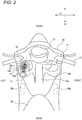
- Fig. 2 is an enlarged top view of the vicinity of receptacle of the straddle-type electric vehicle shown in Fig. 1 as viewed in a direction indicated by an arrow II.
- directions denoted as front, rear, top, bottom, left and right are based on a viewing direction of a rider who rides on an electric motorcycle disposed on a horizontal plane, and who faces a forward traveling direction.
- a front direction is denoted by an arrow X1 and an up-and-down direction is denoted by an arrow Y1.
- a left-and-right direction is denoted by an arrow Z1.
- the configuration of the electric motorcycle will be described based on the electric motorcycle which is parked in an upright erected state with a main stand is rotated downward.
- the electric motorcycle includes a body frame 2, a front wheel 3, a rear wheel 4, a power unit 5 which installs an electric motor, a battery 6, a body cover 7 and a seat 29.
- the electric motor is driven by electric power supplied from the battery 6, and the rear wheel 4 is driven by an output of the electric motor.
- an overall construction of the electric motorcycle will be described sequentially from the front of a body thereof.
- the electric motorcycle has a head pipe 8 which is disposed at a top front portion of the electric motorcycle.
- a steering shaft is turnably inserted into the head pipe 8.
- a pair of left and right front forks is mounted at a lower end portion of the steering shaft.
- the front wheel 3 is mounted to the front forks 10.
- a handlebar 11 is mounted at an upper end portion of the steering shaft. The rider is able to turn the steering shaft, the front forks 10 and the front wheel 3 about an axis of the steering shaft by controlling the handlebar 11.
- Grips 12 are provided individually at both left and right end portions of the handlebar 11 (a left grip only is shown) .
- a right-hand grip makes up a throttle grip. The rider is able to turn this throttle grip to control an output of the electric motor.
- a meter 13 is provided near a center of the handlebar 11.
- the electric motorcycle includes the body frame 2 which extends rearward from the head pipe 8.
- the body frame 2 is formed by using steel tube members.
- the body frame 2 includes a down tube 19 and a frame main body 20 which is disposed rearward of the down tube 19.
- the down tube 19 extends rearward diagonal lower from a lower portion of the head tube 8.
- the frame main body 20 extends rearward from a lower end portion of the down tube 19, and an intermediate portion of the down tube 19 in the front-and-rear direction X1 of the vehicle is formed into an S-shape.
- the frame main body 20 includes a pair of left and right frame main bodies 20, each frame main body 20 including a first frame portion 21, a second frame portion 22 and a third frame portion 23.
- the first frame portion 21 extends substantially straight rearward from the lower end portion of the down tube 19 and is slightly inclined rearward diagonal upper.
- a side stand is mounted to the first frame portion 21.
- the second frame portion 22 is formed into an S-shape as viewed from the side thereof.
- the second frame portion 22 is curved from bottom to top.
- a front end of the second frame portion 22 continues from a rear end portion of the first frame portion 21, an intermediate portion of the second frame portion 22 extends straight rearward diagonal upper, and a rear end portion thereof continues to the third frame portion 23.
- an inclination angle of the intermediate portion of the second frame portion 22 relative to the first frame portion 21 is, for example, on the order of 45 degrees.
- the third frame portion 23 extends in a straight line from an upper end portion of the second frame portion 22 and is inclined rearward diagonal upper.
- the electric motorcycle includes the body cover 7 which is mounted on the body frame 2.
- the body cover 7 includes a front cover 25 which covers the head pipe 8, a leg shield 18, a bottom cover 26, a rear cover 27 and an under-seat cover 28.
- the body cover 7 is a cover constituting an outer surface of the electric motorcycle.
- the bottom cover 26 extends rearward from a lower portion of the front cover 25 to thereby cover the first frame portion 21.
- Foot rest portions 26a are formed at an upper end portion of the bottom cover 26 which is provided between the front wheel 3 and the rear wheel 4.
- the foot rest portions 26a are formed substantially flat and support feet of the rider who is seated on the seat 29 from therebelow.
- the leg shield 18 is provided between the foot rest portions 26a and the front wheel 3 and has a surface which extends in the up-and-down direction. This leg shield 18 covers the down tube 19 together with the front cover 25. The leg shield 18 is formed so as to continue from the rear side of the front cover 25 to the foot rest portions 26a.
- the leg shield 18 has a frame covering portion 18a at a center in the left-and-right direction of the vehicle and leg protecting portions 18b which are provided at the left and right of the frame covering portion 18a.
- the leg protecting portions 18b are provided individually at left and right end portions of the leg shield 18 so as to protect legs of the rider who is seated on the seat 29.
- the frame covering portion 18a is formed in a shape in which it projects rearward from the leg protecting portions 18b so as to cover the down tube 19 which extends rearward diagonal lower from the head tube 8.
- the rear cover 27 covers the second frame portion 22 and the third frame portion 23.
- the rear cover 27 has a shape as a whole in which it extends rearward diagonal upper from a rear portion of the bottom cover 26.
- the rear cover 27 covers from an intermediate portion of the second frame portion 22 to the third frame portion 23 from left and right sides thereof.
- the under-seat cover 28 is formed so as to rise from the rear portion of the bottom cover 26 below the seat 29 and at the front of the rear cover 27.
- the seat 29 is disposed above the under-seat cover 28 and the rear cover 27.
- a front portion of the seat 29 is, with respect to the vehicle, provided forward of the rear wheel 4. While the electric motorcycle is running, the feet of the rider who is seated on the seat 29 rest on the foot rest portions 26a. In the front-and-rear direction X1, the foot rest portions 26a are disposed between the leg shield 18 and the under-seat cover 28.
- the seat 29 is mounted on the under-seat cover 28 via a hinge at a front portion thereof, whereby a storage space provided below the seat 29 can be opened and closed by the seat 29.
- the battery 6 is disposed between the pair of left and right second frame portions 22.
- the battery 6 is a secondary battery which is rechargeable. It is noted that the battery 6 may be configured so as to be detached from the vehicle.
- the power unit 5 is provided rearward of the first frame portion 21 and below the third frame portion 23.
- the power unit 5 is mounted on the third frame portion 23 so as to swing via a suspension unit.
- a main stand is mounted at a lower portion of the power unit 5.
- a receptacle 30 which is to be electrically connected with the battery 6 is provided between the front cover 25 and the leg shield 18.
- the receptacle 30 has a connecting port 31 into which a plug portion 42 of a gun-type plug 40 which is described later can be inserted.
- the receptacle 30 is provided so that the connecting port 31 faces an opening portion A which is provided in the leg shield 18.
- the receptacle 30 may be fitted to a down tube 19 or may be fitted to the body cover 7.
- a cap 32 is provided on the receptacle 30 so as to close the connecting port 31.
- the cap 32 covers the connecting port 31 to thereby prevent the intrusion of rain water or dust into an interior of the receptacle 30.
- a receptacle accommodating portion 18c is provided on the left-side leg protecting portion 18b of the leg shield 18 so as to project rearward from the leg protecting portion 18b.
- An upper surface of the receptacle accommodating portion 18c is formed into a flat plane facing upward.
- the opening portion A is provided in the receptacle accommodating portion 18c.
- the opening portion A is provided in a position which is within a width of the leg shield 18 in a left-and-right direction Z1 of the vehicle. Further, the receptacle 30 facing the opening portion A is provided in an interior of the receptacle accommodating portion 18c in a state that the connecting port faces upward.
- the receptacle 30 includes seven male terminals 33a, 33b. These seven male terminals 33a, 33b are exposed to the connecting port 31. At this connecting port 31, these seven male terminals 33a, 33b are provided in vertex positions of regular hexagon and its center position.
- These male terminals 33a, 33b are respectively connected with two direct current power lines (cathode and anode), an earth line, two interface lines and two communication lines.
- the interface line electrically detects connection between the gun-type plug 40 and the receptacle 30.
- the communication line communicates control signals between a battery charger connected with the gun-type plug 40 and the battery 6 connected with the receptacle 30.
- the two male terminals 33a are made thick with respect to the other four male terminals 33b.
- the two thick male terminals 33a are, as shown, arranged in the front-and-rear direction of the vehicle. In detail, as viewed from top of the vehicle as shown in Fig. 2 , the male terminal 33a positioned rearward is located leftward of the male terminal 33a positioned forward.
- a direction indicated by a line segment connecting these two thick male terminals 33a in Fig. 2 is called as a receptacle-side terminal arrange direction T1.
- the receptacle-side terminal arrange direction T1 is slanted rearward diagonal left with respect to the front-and-rear direction X1 of the vehicle.
- Fig. 3 is a perspective view showing the gun-type plug 40 which is connectable to the receptacle 30.
- the gun-type plug 40 includes a plug portion 42 having female terminals 41a, 41b which are to be connected with the male terminals 33a, 33b of the receptacle 30, and a grip portion 43 which is used as a handle.
- the plug portion 42 is a cylindrical portion formed by extending along with an insertion direction to the receptacle 30.
- plural (seven in the shown example) female terminals 41a, 41b are provided so as to extend in a longitudinal direction of the plug portion 42. These female terminals are exposed to a tip of the plug portion 42.
- the seven female terminals 41a, 41b are respectively provided in vertex positions of a regular hexagon and its center position.
- the two female terminals 41a are set thicker with respect to the other four female terminals 41b.
- a direction indicated by a line segment connecting these two thick female terminals 41a is call as a plug-side terminal arrange direction T2.
- the grip portion 43 extends rearward diagonally with respect to the plug portion 42 so as to be slant with respect to the longitudinal direction of the plug portion 42.
- the grip portion 43 protrudes from the plug portion 42 in the plug-side terminal arrange direction T2. For this reason, when the user handles the gun-type plug 40, a direction of the gun-type plug 40 is naturally determined so that the grip portion 43 is positioned lower than the plug portion 42. In this direction, the two thick female terminals 41a, 41b are arranged in the up-and-down direction and the plug-side terminal arrange direction T2 becomes the up-and-down direction.
- Fig. 4 is a side view showing a state in which the gun-type plug 40 is connected with the receptacle 30.
- Fig.5 is a top view as viewed from an arrow V in Fig. 4 showing the state in which the gun-type plug 40 is connected with the receptacle 30.
- the gun-type plug 40 is connected with the receptacle 30 to thereby charge the battery 6.
- the grip portion 43 positions leftward of the plug portion 42.
- the receptacle 30 is provided so that the receptacle terminal arrange direction T1 is slant rearward diagonal left with respect to the front-and-rear direction of the vehicle.
- the gun-type plug 40 is inserted to the receptacle 30 in a posture in which the grip portion 43 is leftward of the plug portion 42 so that the plug-side terminal arrange direction T2 matches the receptacle-side terminal arrange direction T1.
- the receptacle 30 is provided so that, when the gun-type plug 40 is connected with the receptacle 30, at least a part of the grip portion 43 is, with respect to the vehicle, positioned leftward of the plug portion 42. For this reason, there is no fear that the gun-type plug 40 interferes with the leg shield 18 and thus, the connecting work of the gun-type plug 40 is easy.
- the entire of the gun-plug 40 is accommodated in a space which is within a width of the leg shield 18 in the left-and-right direction Z1 of the vehicle and between the leg shield 18 and the rear wheel 4 in the front-and-rear direction of the vehicle and to which the foot of the occupant who seated on the seat 29 at the time of driving is provided. Therefore, a protrusion amount of the gun-type plug 40 which protrudes sideward of the vehicle can be suppressed.
- the grip portion 43 of the gun-type plug 40 does not protrude sideward from this space, and thus there is no fear to give adverse influence on surrounding during charge.
- the space to which the leg of the occupant is provided is, originally, made empty for accommodating the leg of the occupant. Further, during charge, the occupant does not seat on the seat 29 and the space is available to accommodate the gun-type plug. Therefore, it is not necessary to assure further space for accommodating the gun-type plug 40, and the limited spaces in the electric motorcycle can be effectively utilized.
- the space to which the leg of the occupant is provided is, a concept which does not mean only the space in which the leg of the occupant exist in riding state, but the concept which includes the space to which the leg is passed when the occupant get on and off. That is, the space above the foot rest portions 26a and also the space between the left and right foot rest portions 26a can be used as the space in which the gun-type plug 40 is accommodated during charge. This case, too, it is unnecessary to assure further space for accommodating the gun-type plug 40.
- the grip portion 43 is positioned rearward diagonal left with respect to the plug portion 42 of the gun-type plug 40.
- the user who starts charging work stands the vicinity of the seat 29 at left side of the vehicle.
- the user holds the gun-type plug 40 so that the grip portion 43 is positioned at a side close to his/her body and the plug portion 42 is positioned at a side far from his/her body. Accordingly, when the user brings the gun-type plug 40 close to the receptacle 30, naturally, the grip portion 43 is positioned rearward diagonal left of the plug portion 42. Thus, the connecting work of the gun-type plug 40 to the receptacle 30 is easy.
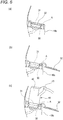
- Fig. 6 is an enlarged side view of the receptacle 30, (a) shows a state in which a cap 32 is closed, (b) shows a state in which the cap 32 is opened and (c) shows a state in which the gun-type plug 40 is connected thereto.
- the gun-type plug 40 is connected with the receptacle 30 so that the plug portion 42 extends rearward diagonal upper of the receptacle 30.
- the user connects the gun-type plug 40 to the receptacle 30 by inserting the gun-type plug 40 to the receptacle 30 from top of the vehicle in the forward diagonal upper direction. Accordingly, the user who starts the charging work while standing the vicinity of the seat 29 can easily recognize the connecting port and thus the connect starting work is easy.
- the opening portion A is provided in the body cover 7 which makes up the outer surface of the electric motorcycle.
- the gun-type plug 40 is located at a position near to the outer surface of the vehicle during charge.
- the protrusion amount of the gun-type plug 40 which protrudes sideward of the vehicle is suppressed. Therefore, it is prevented from affecting adversely on surrounding during charge.
- FIG. 7 is an enlarged side view of a receptacle 30 of a straddle-type electric vehicle according to the second embodiment of the invention.
- (a) of Fig. 7 shows a state in which a cap 32 is closed,
- (b) shows a state in which the cap 32 is opened and
- (c) shows a state in which the gun-type plug 40 is connected thereto.
- the connecting port 31 of the receptacle 30 may be opened rearward diagonal upper and slant to leftward. According to this configuration, the user who stands left side of the vehicle and performs charging work can easily recognize the connecting port 31 and can bring the gun-type plug 40 close to the receptacle 30 in a proper posture. Further, the user can insert the gun-type plug 40 into the receptacle 30 easily.
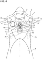
- Fig. 8 is a top view of a straddle-type electric vehicle according to a third embodiment of the invention.
- Fig. 9 shows a configuration in which the gun-type plug 40 is connected with the receptacle 30 shown in Fig. 8 .
- the receptacle 30 is provided in a frame covering portion 18a of the leg shield 18.
- the frame covering portion 18a is positioned between the leg shield 18 and the seat 29 and upward of the foot rest portions (refer to Fig. 1 ). Further, as shown in Fig. 8 , in a plane view, at least a part of the frame covering portion 18a is positioned between the left and right foot rest portions 26a in a width direction of the vehicle.
- the opening portion A is provided in the frame covering portion 18. For this reason, at least a part (right half) of the receptacle 30 which faces the opening portion A is positioned rightward of a center of the vehicle.
- the entire of the gun-type plug 40 can be put right aside of the vehicle. Therefore, according to the configuration of this embodiment, the grip portion 43 of the gun-type plug 40 does not protrude sideward of the vehicle more surely. Further, a space which is left side of the leg shield can be used as a small article accommodation space.
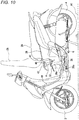
- FIG. 10 is a side view of a straddle-type electric vehicle according a fourth not claimed embodiment.
- the opening portion A may be provided in the under-seat cover 28.
- the under-seat cover 28 of the electric motorcycle according this embodiment is provided with a step portion 28a protruding forward under the seat 29.
- the opening portion A is provided on a flat upper surface of the step portion 28a.
- the grip portion 43 of the gun-type plug 40 is positioned forward diagonal left of the plug 42. For this reason, there is no fear in which the gun-type plug 40 interferes with the seat 29, the connecting work is easy. Further, because it is prevented for the gun-type plug 40 from protruding sideward of the vehicle at the time of charging, adverse influence on surrounding can be reduced.
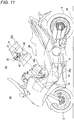
- FIG. 11 shows an electric vehicle according to a fifth embodiment of the invention, (a) is a side view and (b) is a top view showing the receptacle.
- a tunnel portion 17 is provided between the frame covering portion 18a which is provided at a center in a left-and-right direction of the leg shield 18 and the seat 29.
- the tunnel portion 17 is positioned between the leg shield 18 and the seat 29 and upward of the foot rest portions.
- at least a part of the tunnel portion 17 is positioned between the left and right foot portions 26a in the width direction of the vehicle.
- the opening portion A to which the connecting port 31 of the receptacle 30 faces is provided on an upper surface of the tunnel portion 17.
- the receptacle 30 is provided in an interior of the tunnel portion 17 so that the connecting port 31 opens upward.
- the receptacle is provided so that the grip portion 43 is, with respect to the vehicle, positioned leftward of the plug portion 42 when the gun-type plug 40 is connected with the receptacle 30.
- the tunnel portion 17 is positioned within the width direction of the leg shield 18 in left-and-right direction.
- the opening portion A is provided at a center of the width direction of the vehicle, when charging the battery 6, it is prevented for the gun-type plug 40 from protruding sideward.
- the gun-type plug 40 is contacted with other vehicles, the adverse influence on the surrounding can be reduced.
- the board-shaped foot rest portions 26 are formed on the body cover 7, the invention is not limited thereto.
- the foot rest portion may be configured by a rod-shaped metal member.
- the connecting port 31 of the receptacle 30 is closable by the cap 32 attached to the receptacle
- the invention is not limited thereto.
- a configuration in which the cap is attached to the leg shield 18, the under-seat cover 28 or the tunnel portion 17 on which the opening portion A is provided may be adoptable.
- the gun-type plug 40 has seven male terminals 33a, 33b and the receptacle 30 has seven female terminals 41a, 41b are explained, however, the present invention is not limited thereto.
- the communication lines is designed to have a function of that of the interface line, too, and the gun-type plug 40 has five male terminals 33a, 33b and the receptacle 30 has five female terminals 41a, 41b so that respective five electric wires are connected.
- a straddle-type electric vehicle in which the gun-type plug can be provided in the space between the left and right foot rest portions and the influence on the surrounding is reduced.
Landscapes
- Engineering & Computer Science (AREA)
- Mechanical Engineering (AREA)
- Transportation (AREA)
- Power Engineering (AREA)
- Sustainable Energy (AREA)
- Life Sciences & Earth Sciences (AREA)
- Sustainable Development (AREA)
- Chemical & Material Sciences (AREA)
- Combustion & Propulsion (AREA)
- Electric Propulsion And Braking For Vehicles (AREA)
- Connector Housings Or Holding Contact Members (AREA)
- Details Of Connecting Devices For Male And Female Coupling (AREA)
- Automatic Cycles, And Cycles In General (AREA)
- Arrangement Or Mounting Of Propulsion Units For Vehicles (AREA)
Applications Claiming Priority (3)
| Application Number | Priority Date | Filing Date | Title |
|---|---|---|---|
| JP2011280757 | 2011-12-22 | ||
| JP2012265126 | 2012-12-04 | ||
| PCT/JP2012/082649 WO2013094558A1 (ja) | 2011-12-22 | 2012-12-17 | 鞍乗型電動車両 |
Publications (3)
| Publication Number | Publication Date |
|---|---|
| EP2796351A1 EP2796351A1 (en) | 2014-10-29 |
| EP2796351A4 EP2796351A4 (en) | 2015-05-20 |
| EP2796351B1 true EP2796351B1 (en) | 2021-10-06 |
Family
ID=48668448
Family Applications (1)
| Application Number | Title | Priority Date | Filing Date |
|---|---|---|---|
| EP12858988.4A Active EP2796351B1 (en) | 2011-12-22 | 2012-12-17 | Saddled electric vehicle |
Country Status (8)
| Country | Link |
|---|---|
| US (1) | US9090310B2 (enExample) |
| EP (1) | EP2796351B1 (enExample) |
| JP (1) | JP5946845B2 (enExample) |
| CN (1) | CN104010934B (enExample) |
| BR (1) | BR112014015371A2 (enExample) |
| IN (1) | IN2014KN01313A (enExample) |
| TW (1) | TWI593588B (enExample) |
| WO (1) | WO2013094558A1 (enExample) |
Families Citing this family (14)
| Publication number | Priority date | Publication date | Assignee | Title |
|---|---|---|---|---|
| JP5627154B2 (ja) * | 2011-12-28 | 2014-11-19 | 川崎重工業株式会社 | 鞍乗型電動車両 |
| JP6279867B2 (ja) * | 2013-09-30 | 2018-02-14 | 本田技研工業株式会社 | 電動車両 |
| CN106654717A (zh) * | 2015-11-03 | 2017-05-10 | 鸿富锦精密工业(深圳)有限公司 | 充电枪及充电连接器 |
| TWI603546B (zh) * | 2015-11-03 | 2017-10-21 | 鴻海精密工業股份有限公司 | 充電槍及充電連接器 |
| JP6235059B2 (ja) * | 2016-03-15 | 2017-11-22 | 本田技研工業株式会社 | リッド保持構造 |
| JP6474372B2 (ja) | 2016-09-23 | 2019-02-27 | 本田技研工業株式会社 | 鞍乗型車両のアクセサリソケット構造 |
| JP6479116B1 (ja) * | 2017-08-31 | 2019-03-06 | ヤマハ発動機株式会社 | 電動二輪車 |
| US11390350B2 (en) | 2018-08-07 | 2022-07-19 | Harley-Davidson Motor Company Group, LLC | Seat caddy for charging cable |
| JP2020032945A (ja) * | 2018-08-31 | 2020-03-05 | ヤマハ発動機株式会社 | 鞍乗型車両 |
| CN112770965B (zh) * | 2018-09-27 | 2022-06-17 | 本田技研工业株式会社 | 电动车辆 |
| CN111422291B (zh) * | 2018-12-21 | 2021-11-09 | 本田技研工业株式会社 | 跨骑型车辆 |
| WO2022075206A1 (ja) * | 2020-10-05 | 2022-04-14 | 株式会社クボタ | 電動トラクタ |
| CN112849315B (zh) * | 2020-11-10 | 2022-08-16 | 浙江春风动力股份有限公司 | 一种结构稳定的电动摩托车 |
| IN202041054371A (enExample) * | 2020-12-14 | 2022-06-17 |
Family Cites Families (27)
| Publication number | Priority date | Publication date | Assignee | Title |
|---|---|---|---|---|
| JPH0519275Y2 (enExample) * | 1986-10-14 | 1993-05-20 | ||
| JP3179508B2 (ja) | 1991-02-27 | 2001-06-25 | 本田技研工業株式会社 | 電動車両用充電装置 |
| JP3343361B2 (ja) * | 1991-06-05 | 2002-11-11 | ヤマハ発動機株式会社 | 電動二輪車における充電装置 |
| JP3336529B2 (ja) * | 1992-10-26 | 2002-10-21 | ヤマハ発動機株式会社 | 電動スクータ |
| JPH06290831A (ja) * | 1993-04-01 | 1994-10-18 | Sumitomo Wiring Syst Ltd | 電気自動車充電用コネクタ |
| US5429524A (en) * | 1993-04-16 | 1995-07-04 | Sumitomo Wiring Systems, Ltd. | Coupling device of charging connector assembly for electric car |
| JP3347433B2 (ja) * | 1993-10-19 | 2002-11-20 | 本田技研工業株式会社 | 電動車両の充電コード収納構造 |
| JP3433432B2 (ja) | 1993-12-28 | 2003-08-04 | 矢崎総業株式会社 | 給電コネクタ |
| NL1018948C2 (nl) * | 2001-09-13 | 2003-03-20 | Sparta B V | Rijwiel met hulpaandrijving. |
| US6593721B1 (en) * | 2001-12-20 | 2003-07-15 | Link Treasure Limited | Connection device for charging electric vehicles |
| CN2582972Y (zh) * | 2002-10-22 | 2003-10-29 | 光阳工业股份有限公司 | 具前置式加油口的摩托车置物装置 |
| CN100473577C (zh) * | 2004-08-26 | 2009-04-01 | 光阳工业股份有限公司 | 一种摩托车的配置构造 |
| US20100228405A1 (en) * | 2007-06-13 | 2010-09-09 | Intrago Corporation | Shared vehicle management system |
| CN201321124Y (zh) * | 2008-12-11 | 2009-10-07 | 洛阳北方易初摩托车有限公司 | 具有外接电源充电功能的摩托车 |
| JP5327459B2 (ja) * | 2009-04-03 | 2013-10-30 | スズキ株式会社 | 自動二輪車のガス燃料充填口配置構造 |
| JP5500865B2 (ja) * | 2009-04-30 | 2014-05-21 | 日東工業株式会社 | 電気自動車用充電スタンド |
| JP5340046B2 (ja) * | 2009-06-12 | 2013-11-13 | 富士重工業株式会社 | 充電装置および充電構造 |
| US9070925B2 (en) | 2009-08-31 | 2015-06-30 | Honda Motor Co., Ltd. | Battery charger and battery charger attaching structure |
| BR112012005886A2 (pt) * | 2009-09-15 | 2020-08-18 | Honda Motor Co., Ltd | veículo elétrico com duas ou três rodas |
| IN2012DN01766A (enExample) | 2009-09-15 | 2015-06-05 | Honda Motor Co Ltd | |
| JP5597376B2 (ja) * | 2009-09-15 | 2014-10-01 | 本田技研工業株式会社 | 自動二輪車 |
| JP5254164B2 (ja) * | 2009-09-15 | 2013-08-07 | 本田技研工業株式会社 | 電動二輪車 |
| JP5237230B2 (ja) | 2009-09-15 | 2013-07-17 | 本田技研工業株式会社 | 電動二輪車 |
| TWM382921U (en) | 2010-01-14 | 2010-06-21 | Sanyang Industry Co Ltd | Charging apparatus |
| JP5595227B2 (ja) * | 2010-10-29 | 2014-09-24 | 本田技研工業株式会社 | 電動二輪車 |
| JP5595228B2 (ja) * | 2010-10-29 | 2014-09-24 | 本田技研工業株式会社 | 電動車両 |
| EP2662271B1 (en) * | 2010-12-27 | 2017-03-08 | Kawasaki Jukogyo Kabushiki Kaisha | Electric motorcycle |
-
2012
- 2012-12-17 IN IN1313KON2014 patent/IN2014KN01313A/en unknown
- 2012-12-17 US US14/366,752 patent/US9090310B2/en not_active Expired - Fee Related
- 2012-12-17 CN CN201280063742.8A patent/CN104010934B/zh active Active
- 2012-12-17 WO PCT/JP2012/082649 patent/WO2013094558A1/ja not_active Ceased
- 2012-12-17 BR BR112014015371A patent/BR112014015371A2/pt not_active IP Right Cessation
- 2012-12-17 EP EP12858988.4A patent/EP2796351B1/en active Active
- 2012-12-17 JP JP2013550268A patent/JP5946845B2/ja active Active
- 2012-12-21 TW TW101149181A patent/TWI593588B/zh active
Non-Patent Citations (1)
| Title |
|---|
| None * |
Also Published As
| Publication number | Publication date |
|---|---|
| JPWO2013094558A1 (ja) | 2015-04-27 |
| EP2796351A1 (en) | 2014-10-29 |
| BR112014015371A8 (pt) | 2017-06-13 |
| IN2014KN01313A (enExample) | 2015-10-16 |
| US20140345962A1 (en) | 2014-11-27 |
| JP5946845B2 (ja) | 2016-07-06 |
| CN104010934B (zh) | 2017-07-21 |
| WO2013094558A1 (ja) | 2013-06-27 |
| CN104010934A (zh) | 2014-08-27 |
| TW201345778A (zh) | 2013-11-16 |
| BR112014015371A2 (pt) | 2017-06-13 |
| US9090310B2 (en) | 2015-07-28 |
| TWI593588B (zh) | 2017-08-01 |
| EP2796351A4 (en) | 2015-05-20 |
Similar Documents
| Publication | Publication Date | Title |
|---|---|---|
| EP2796351A1 (en) | Saddled electric vehicle | |
| EP2796352B1 (en) | Saddled electric vehicle | |
| EP2772420B1 (en) | Electric vehicle | |
| AU2012258294B2 (en) | Power supply device for electric vehicle | |
| EP2626231B1 (en) | Power supply device for electric vehicle | |
| KR102066895B1 (ko) | 과좌식 차량 | |
| EP4122749B1 (en) | Charging ports of an electric straddled vehicle | |
| EP3450296B1 (en) | Electric motorcycle | |
| JP2016199236A (ja) | 充電用ケーブルを用いて充電する鞍乗型電動車両 | |
| JP2017190071A (ja) | 鞍乗型電動車両 | |
| CN102991617A (zh) | 鞍乘型车辆的移动终端支承结构 | |
| HK1214220A1 (zh) | 用於小型摩托车的电气辅助插座安装结构 | |
| PH12019050009A1 (en) | Straddled vehicle | |
| TW201242806A (en) | Electric vehicle | |
| JP2013129344A (ja) | 鞍乗型電動車両 | |
| JP5964323B2 (ja) | 鞍乗型電動車両 | |
| JP2013129343A (ja) | 鞍乗型電動車両 | |
| JP5665705B2 (ja) | 鞍乗り型車両のモバイル端末支持構造 | |
| JPH11321753A (ja) | 電動車両における充電器の配置構造 | |
| US20260015058A1 (en) | Electric straddled vehicle | |
| CN118419186A (zh) | 鞍乘型车辆 |
Legal Events
| Date | Code | Title | Description |
|---|---|---|---|
| PUAI | Public reference made under article 153(3) epc to a published international application that has entered the european phase |
Free format text: ORIGINAL CODE: 0009012 |
|
| 17P | Request for examination filed |
Effective date: 20140620 |
|
| AK | Designated contracting states |
Kind code of ref document: A1 Designated state(s): AL AT BE BG CH CY CZ DE DK EE ES FI FR GB GR HR HU IE IS IT LI LT LU LV MC MK MT NL NO PL PT RO RS SE SI SK SM TR |
|
| DAX | Request for extension of the european patent (deleted) | ||
| RA4 | Supplementary search report drawn up and despatched (corrected) |
Effective date: 20150421 |
|
| RIC1 | Information provided on ipc code assigned before grant |
Ipc: B62M 7/12 20060101ALI20150415BHEP Ipc: B62J 23/00 20060101ALI20150415BHEP Ipc: B62J 99/00 20090101AFI20150415BHEP Ipc: B60L 11/18 20060101ALI20150415BHEP |
|
| STAA | Information on the status of an ep patent application or granted ep patent |
Free format text: STATUS: EXAMINATION IS IN PROGRESS |
|
| 17Q | First examination report despatched |
Effective date: 20190424 |
|
| REG | Reference to a national code |
Ref country code: DE Ref legal event code: R079 Ref document number: 602012076875 Country of ref document: DE Free format text: PREVIOUS MAIN CLASS: B62J0099000000 Ipc: B62K0011100000 |
|
| GRAP | Despatch of communication of intention to grant a patent |
Free format text: ORIGINAL CODE: EPIDOSNIGR1 |
|
| STAA | Information on the status of an ep patent application or granted ep patent |
Free format text: STATUS: GRANT OF PATENT IS INTENDED |
|
| RIC1 | Information provided on ipc code assigned before grant |
Ipc: B62K 11/10 20060101AFI20210518BHEP Ipc: B60L 53/16 20190101ALI20210518BHEP |
|
| INTG | Intention to grant announced |
Effective date: 20210608 |
|
| GRAS | Grant fee paid |
Free format text: ORIGINAL CODE: EPIDOSNIGR3 |
|
| GRAA | (expected) grant |
Free format text: ORIGINAL CODE: 0009210 |
|
| STAA | Information on the status of an ep patent application or granted ep patent |
Free format text: STATUS: THE PATENT HAS BEEN GRANTED |
|
| AK | Designated contracting states |
Kind code of ref document: B1 Designated state(s): AL AT BE BG CH CY CZ DE DK EE ES FI FR GB GR HR HU IE IS IT LI LT LU LV MC MK MT NL NO PL PT RO RS SE SI SK SM TR |
|
| REG | Reference to a national code |
Ref country code: GB Ref legal event code: FG4D |
|
| REG | Reference to a national code |
Ref country code: CH Ref legal event code: EP Ref country code: AT Ref legal event code: REF Ref document number: 1436003 Country of ref document: AT Kind code of ref document: T Effective date: 20211015 |
|
| REG | Reference to a national code |
Ref country code: IE Ref legal event code: FG4D |
|
| REG | Reference to a national code |
Ref country code: DE Ref legal event code: R096 Ref document number: 602012076875 Country of ref document: DE |
|
| REG | Reference to a national code |
Ref country code: LT Ref legal event code: MG9D |
|
| REG | Reference to a national code |
Ref country code: NL Ref legal event code: MP Effective date: 20211006 |
|
| REG | Reference to a national code |
Ref country code: AT Ref legal event code: MK05 Ref document number: 1436003 Country of ref document: AT Kind code of ref document: T Effective date: 20211006 |
|
| PG25 | Lapsed in a contracting state [announced via postgrant information from national office to epo] |
Ref country code: RS Free format text: LAPSE BECAUSE OF FAILURE TO SUBMIT A TRANSLATION OF THE DESCRIPTION OR TO PAY THE FEE WITHIN THE PRESCRIBED TIME-LIMIT Effective date: 20211006 Ref country code: LT Free format text: LAPSE BECAUSE OF FAILURE TO SUBMIT A TRANSLATION OF THE DESCRIPTION OR TO PAY THE FEE WITHIN THE PRESCRIBED TIME-LIMIT Effective date: 20211006 Ref country code: FI Free format text: LAPSE BECAUSE OF FAILURE TO SUBMIT A TRANSLATION OF THE DESCRIPTION OR TO PAY THE FEE WITHIN THE PRESCRIBED TIME-LIMIT Effective date: 20211006 Ref country code: BG Free format text: LAPSE BECAUSE OF FAILURE TO SUBMIT A TRANSLATION OF THE DESCRIPTION OR TO PAY THE FEE WITHIN THE PRESCRIBED TIME-LIMIT Effective date: 20220106 Ref country code: AT Free format text: LAPSE BECAUSE OF FAILURE TO SUBMIT A TRANSLATION OF THE DESCRIPTION OR TO PAY THE FEE WITHIN THE PRESCRIBED TIME-LIMIT Effective date: 20211006 |
|
| PG25 | Lapsed in a contracting state [announced via postgrant information from national office to epo] |
Ref country code: IS Free format text: LAPSE BECAUSE OF FAILURE TO SUBMIT A TRANSLATION OF THE DESCRIPTION OR TO PAY THE FEE WITHIN THE PRESCRIBED TIME-LIMIT Effective date: 20220206 Ref country code: SE Free format text: LAPSE BECAUSE OF FAILURE TO SUBMIT A TRANSLATION OF THE DESCRIPTION OR TO PAY THE FEE WITHIN THE PRESCRIBED TIME-LIMIT Effective date: 20211006 Ref country code: PT Free format text: LAPSE BECAUSE OF FAILURE TO SUBMIT A TRANSLATION OF THE DESCRIPTION OR TO PAY THE FEE WITHIN THE PRESCRIBED TIME-LIMIT Effective date: 20220207 Ref country code: PL Free format text: LAPSE BECAUSE OF FAILURE TO SUBMIT A TRANSLATION OF THE DESCRIPTION OR TO PAY THE FEE WITHIN THE PRESCRIBED TIME-LIMIT Effective date: 20211006 Ref country code: NO Free format text: LAPSE BECAUSE OF FAILURE TO SUBMIT A TRANSLATION OF THE DESCRIPTION OR TO PAY THE FEE WITHIN THE PRESCRIBED TIME-LIMIT Effective date: 20220106 Ref country code: NL Free format text: LAPSE BECAUSE OF FAILURE TO SUBMIT A TRANSLATION OF THE DESCRIPTION OR TO PAY THE FEE WITHIN THE PRESCRIBED TIME-LIMIT Effective date: 20211006 Ref country code: LV Free format text: LAPSE BECAUSE OF FAILURE TO SUBMIT A TRANSLATION OF THE DESCRIPTION OR TO PAY THE FEE WITHIN THE PRESCRIBED TIME-LIMIT Effective date: 20211006 Ref country code: HR Free format text: LAPSE BECAUSE OF FAILURE TO SUBMIT A TRANSLATION OF THE DESCRIPTION OR TO PAY THE FEE WITHIN THE PRESCRIBED TIME-LIMIT Effective date: 20211006 Ref country code: GR Free format text: LAPSE BECAUSE OF FAILURE TO SUBMIT A TRANSLATION OF THE DESCRIPTION OR TO PAY THE FEE WITHIN THE PRESCRIBED TIME-LIMIT Effective date: 20220107 Ref country code: ES Free format text: LAPSE BECAUSE OF FAILURE TO SUBMIT A TRANSLATION OF THE DESCRIPTION OR TO PAY THE FEE WITHIN THE PRESCRIBED TIME-LIMIT Effective date: 20211006 |
|
| REG | Reference to a national code |
Ref country code: DE Ref legal event code: R097 Ref document number: 602012076875 Country of ref document: DE |
|
| PG25 | Lapsed in a contracting state [announced via postgrant information from national office to epo] |
Ref country code: SM Free format text: LAPSE BECAUSE OF FAILURE TO SUBMIT A TRANSLATION OF THE DESCRIPTION OR TO PAY THE FEE WITHIN THE PRESCRIBED TIME-LIMIT Effective date: 20211006 Ref country code: SK Free format text: LAPSE BECAUSE OF FAILURE TO SUBMIT A TRANSLATION OF THE DESCRIPTION OR TO PAY THE FEE WITHIN THE PRESCRIBED TIME-LIMIT Effective date: 20211006 Ref country code: RO Free format text: LAPSE BECAUSE OF FAILURE TO SUBMIT A TRANSLATION OF THE DESCRIPTION OR TO PAY THE FEE WITHIN THE PRESCRIBED TIME-LIMIT Effective date: 20211006 Ref country code: MC Free format text: LAPSE BECAUSE OF FAILURE TO SUBMIT A TRANSLATION OF THE DESCRIPTION OR TO PAY THE FEE WITHIN THE PRESCRIBED TIME-LIMIT Effective date: 20211006 Ref country code: EE Free format text: LAPSE BECAUSE OF FAILURE TO SUBMIT A TRANSLATION OF THE DESCRIPTION OR TO PAY THE FEE WITHIN THE PRESCRIBED TIME-LIMIT Effective date: 20211006 Ref country code: DK Free format text: LAPSE BECAUSE OF FAILURE TO SUBMIT A TRANSLATION OF THE DESCRIPTION OR TO PAY THE FEE WITHIN THE PRESCRIBED TIME-LIMIT Effective date: 20211006 Ref country code: CZ Free format text: LAPSE BECAUSE OF FAILURE TO SUBMIT A TRANSLATION OF THE DESCRIPTION OR TO PAY THE FEE WITHIN THE PRESCRIBED TIME-LIMIT Effective date: 20211006 |
|
| REG | Reference to a national code |
Ref country code: CH Ref legal event code: PL |
|
| PLBE | No opposition filed within time limit |
Free format text: ORIGINAL CODE: 0009261 |
|
| STAA | Information on the status of an ep patent application or granted ep patent |
Free format text: STATUS: NO OPPOSITION FILED WITHIN TIME LIMIT |
|
| 26N | No opposition filed |
Effective date: 20220707 |
|
| REG | Reference to a national code |
Ref country code: BE Ref legal event code: MM Effective date: 20211231 |
|
| GBPC | Gb: european patent ceased through non-payment of renewal fee |
Effective date: 20220106 |
|
| PG25 | Lapsed in a contracting state [announced via postgrant information from national office to epo] |
Ref country code: LU Free format text: LAPSE BECAUSE OF NON-PAYMENT OF DUE FEES Effective date: 20211217 Ref country code: IE Free format text: LAPSE BECAUSE OF NON-PAYMENT OF DUE FEES Effective date: 20211217 Ref country code: GB Free format text: LAPSE BECAUSE OF NON-PAYMENT OF DUE FEES Effective date: 20220106 Ref country code: AL Free format text: LAPSE BECAUSE OF FAILURE TO SUBMIT A TRANSLATION OF THE DESCRIPTION OR TO PAY THE FEE WITHIN THE PRESCRIBED TIME-LIMIT Effective date: 20211006 |
|
| PG25 | Lapsed in a contracting state [announced via postgrant information from national office to epo] |
Ref country code: SI Free format text: LAPSE BECAUSE OF FAILURE TO SUBMIT A TRANSLATION OF THE DESCRIPTION OR TO PAY THE FEE WITHIN THE PRESCRIBED TIME-LIMIT Effective date: 20211006 Ref country code: BE Free format text: LAPSE BECAUSE OF NON-PAYMENT OF DUE FEES Effective date: 20211231 |
|
| PG25 | Lapsed in a contracting state [announced via postgrant information from national office to epo] |
Ref country code: LI Free format text: LAPSE BECAUSE OF NON-PAYMENT OF DUE FEES Effective date: 20211231 Ref country code: CH Free format text: LAPSE BECAUSE OF NON-PAYMENT OF DUE FEES Effective date: 20211231 |
|
| PG25 | Lapsed in a contracting state [announced via postgrant information from national office to epo] |
Ref country code: HU Free format text: LAPSE BECAUSE OF FAILURE TO SUBMIT A TRANSLATION OF THE DESCRIPTION OR TO PAY THE FEE WITHIN THE PRESCRIBED TIME-LIMIT; INVALID AB INITIO Effective date: 20121217 Ref country code: CY Free format text: LAPSE BECAUSE OF FAILURE TO SUBMIT A TRANSLATION OF THE DESCRIPTION OR TO PAY THE FEE WITHIN THE PRESCRIBED TIME-LIMIT Effective date: 20211006 |
|
| P01 | Opt-out of the competence of the unified patent court (upc) registered |
Effective date: 20230527 |
|
| PG25 | Lapsed in a contracting state [announced via postgrant information from national office to epo] |
Ref country code: MK Free format text: LAPSE BECAUSE OF FAILURE TO SUBMIT A TRANSLATION OF THE DESCRIPTION OR TO PAY THE FEE WITHIN THE PRESCRIBED TIME-LIMIT Effective date: 20211006 |
|
| PG25 | Lapsed in a contracting state [announced via postgrant information from national office to epo] |
Ref country code: TR Free format text: LAPSE BECAUSE OF FAILURE TO SUBMIT A TRANSLATION OF THE DESCRIPTION OR TO PAY THE FEE WITHIN THE PRESCRIBED TIME-LIMIT Effective date: 20211006 |
|
| PG25 | Lapsed in a contracting state [announced via postgrant information from national office to epo] |
Ref country code: MT Free format text: LAPSE BECAUSE OF FAILURE TO SUBMIT A TRANSLATION OF THE DESCRIPTION OR TO PAY THE FEE WITHIN THE PRESCRIBED TIME-LIMIT Effective date: 20211006 |
|
| PGFP | Annual fee paid to national office [announced via postgrant information from national office to epo] |
Ref country code: DE Payment date: 20251211 Year of fee payment: 14 |
|
| PGFP | Annual fee paid to national office [announced via postgrant information from national office to epo] |
Ref country code: IT Payment date: 20251223 Year of fee payment: 14 |
|
| PGFP | Annual fee paid to national office [announced via postgrant information from national office to epo] |
Ref country code: FR Payment date: 20251223 Year of fee payment: 14 |