EP2795379B1 - Fibre de diffusion de lumière de couleur blanche uniforme - Google Patents
Fibre de diffusion de lumière de couleur blanche uniforme Download PDFInfo
- Publication number
- EP2795379B1 EP2795379B1 EP12806288.2A EP12806288A EP2795379B1 EP 2795379 B1 EP2795379 B1 EP 2795379B1 EP 12806288 A EP12806288 A EP 12806288A EP 2795379 B1 EP2795379 B1 EP 2795379B1
- Authority
- EP
- European Patent Office
- Prior art keywords
- fiber
- light diffusing
- light
- scattering
- optical fiber
- Prior art date
- Legal status (The legal status is an assumption and is not a legal conclusion. Google has not performed a legal analysis and makes no representation as to the accuracy of the status listed.)
- Active
Links
- 239000000835 fiber Substances 0.000 title claims description 140
- 239000013307 optical fiber Substances 0.000 claims description 102
- 238000005253 cladding Methods 0.000 claims description 77
- 238000000576 coating method Methods 0.000 claims description 73
- 239000011248 coating agent Substances 0.000 claims description 64
- 229920000642 polymer Polymers 0.000 claims description 46
- 239000000463 material Substances 0.000 claims description 45
- VYPSYNLAJGMNEJ-UHFFFAOYSA-N Silicium dioxide Chemical compound O=[Si]=O VYPSYNLAJGMNEJ-UHFFFAOYSA-N 0.000 claims description 41
- OAICVXFJPJFONN-UHFFFAOYSA-N Phosphorus Chemical compound [P] OAICVXFJPJFONN-UHFFFAOYSA-N 0.000 claims description 30
- GWEVSGVZZGPLCZ-UHFFFAOYSA-N Titan oxide Chemical compound O=[Ti]=O GWEVSGVZZGPLCZ-UHFFFAOYSA-N 0.000 claims description 20
- 238000000034 method Methods 0.000 claims description 19
- 239000002105 nanoparticle Substances 0.000 claims description 13
- 239000000377 silicon dioxide Substances 0.000 claims description 13
- 239000011521 glass Substances 0.000 claims description 10
- 239000011859 microparticle Substances 0.000 claims description 10
- 229910052681 coesite Inorganic materials 0.000 claims description 7
- 229910052906 cristobalite Inorganic materials 0.000 claims description 7
- 229910052682 stishovite Inorganic materials 0.000 claims description 7
- 229910052905 tridymite Inorganic materials 0.000 claims description 7
- 239000002096 quantum dot Substances 0.000 claims description 3
- 235000012239 silicon dioxide Nutrition 0.000 claims 1
- 239000010410 layer Substances 0.000 description 100
- 239000002245 particle Substances 0.000 description 34
- 239000000203 mixture Substances 0.000 description 21
- 239000007789 gas Substances 0.000 description 12
- 238000005286 illumination Methods 0.000 description 12
- 238000001228 spectrum Methods 0.000 description 12
- 238000009826 distribution Methods 0.000 description 9
- NIXOWILDQLNWCW-UHFFFAOYSA-M Acrylate Chemical compound [O-]C(=O)C=C NIXOWILDQLNWCW-UHFFFAOYSA-M 0.000 description 8
- 230000004323 axial length Effects 0.000 description 6
- 239000003795 chemical substances by application Substances 0.000 description 6
- 239000012141 concentrate Substances 0.000 description 6
- 239000007788 liquid Substances 0.000 description 6
- 229920001296 polysiloxane Polymers 0.000 description 6
- -1 CPC6 Chemical compound 0.000 description 4
- 230000009102 absorption Effects 0.000 description 4
- 238000010521 absorption reaction Methods 0.000 description 4
- 238000001816 cooling Methods 0.000 description 4
- 230000000694 effects Effects 0.000 description 4
- 229910052731 fluorine Inorganic materials 0.000 description 4
- ZYMKZMDQUPCXRP-UHFFFAOYSA-N fluoro prop-2-enoate Chemical compound FOC(=O)C=C ZYMKZMDQUPCXRP-UHFFFAOYSA-N 0.000 description 4
- 238000004519 manufacturing process Methods 0.000 description 4
- 230000037361 pathway Effects 0.000 description 4
- 239000002356 single layer Substances 0.000 description 4
- PXGOKWXKJXAPGV-UHFFFAOYSA-N Fluorine Chemical compound FF PXGOKWXKJXAPGV-UHFFFAOYSA-N 0.000 description 3
- 230000008901 benefit Effects 0.000 description 3
- 239000011247 coating layer Substances 0.000 description 3
- 238000009792 diffusion process Methods 0.000 description 3
- 239000002019 doping agent Substances 0.000 description 3
- 238000000605 extraction Methods 0.000 description 3
- 239000011737 fluorine Substances 0.000 description 3
- 238000002156 mixing Methods 0.000 description 3
- 239000007787 solid Substances 0.000 description 3
- IJGRMHOSHXDMSA-UHFFFAOYSA-N Atomic nitrogen Chemical compound N#N IJGRMHOSHXDMSA-UHFFFAOYSA-N 0.000 description 2
- ZOXJGFHDIHLPTG-UHFFFAOYSA-N Boron Chemical compound [B] ZOXJGFHDIHLPTG-UHFFFAOYSA-N 0.000 description 2
- 102100027047 Cell division control protein 6 homolog Human genes 0.000 description 2
- 101000914465 Homo sapiens Cell division control protein 6 homolog Proteins 0.000 description 2
- XLOMVQKBTHCTTD-UHFFFAOYSA-N Zinc monoxide Chemical compound [Zn]=O XLOMVQKBTHCTTD-UHFFFAOYSA-N 0.000 description 2
- 238000002835 absorbance Methods 0.000 description 2
- 238000000149 argon plasma sintering Methods 0.000 description 2
- 229910052796 boron Inorganic materials 0.000 description 2
- 150000001875 compounds Chemical class 0.000 description 2
- 238000010586 diagram Methods 0.000 description 2
- UHESRSKEBRADOO-UHFFFAOYSA-N ethyl carbamate;prop-2-enoic acid Chemical compound OC(=O)C=C.CCOC(N)=O UHESRSKEBRADOO-UHFFFAOYSA-N 0.000 description 2
- 239000003365 glass fiber Substances 0.000 description 2
- 229910044991 metal oxide Inorganic materials 0.000 description 2
- 150000004706 metal oxides Chemical class 0.000 description 2
- 230000002093 peripheral effect Effects 0.000 description 2
- 230000008569 process Effects 0.000 description 2
- 230000001902 propagating effect Effects 0.000 description 2
- 238000002371 ultraviolet--visible spectrum Methods 0.000 description 2
- 230000002745 absorbent Effects 0.000 description 1
- 239000002250 absorbent Substances 0.000 description 1
- 230000006978 adaptation Effects 0.000 description 1
- 239000000654 additive Substances 0.000 description 1
- 238000004887 air purification Methods 0.000 description 1
- QVGXLLKOCUKJST-UHFFFAOYSA-N atomic oxygen Chemical compound [O] QVGXLLKOCUKJST-UHFFFAOYSA-N 0.000 description 1
- 230000009286 beneficial effect Effects 0.000 description 1
- 229910010293 ceramic material Inorganic materials 0.000 description 1
- 230000008859 change Effects 0.000 description 1
- 239000003086 colorant Substances 0.000 description 1
- 239000000306 component Substances 0.000 description 1
- 230000002596 correlated effect Effects 0.000 description 1
- 230000000875 corresponding effect Effects 0.000 description 1
- 230000008878 coupling Effects 0.000 description 1
- 238000010168 coupling process Methods 0.000 description 1
- 238000005859 coupling reaction Methods 0.000 description 1
- 230000007812 deficiency Effects 0.000 description 1
- 238000000295 emission spectrum Methods 0.000 description 1
- 239000002241 glass-ceramic Substances 0.000 description 1
- 239000004615 ingredient Substances 0.000 description 1
- 239000003999 initiator Substances 0.000 description 1
- 229910010272 inorganic material Inorganic materials 0.000 description 1
- 239000011147 inorganic material Substances 0.000 description 1
- 230000003993 interaction Effects 0.000 description 1
- 239000004973 liquid crystal related substance Substances 0.000 description 1
- 238000005259 measurement Methods 0.000 description 1
- 239000002184 metal Substances 0.000 description 1
- 238000012986 modification Methods 0.000 description 1
- 230000004048 modification Effects 0.000 description 1
- 229910052757 nitrogen Inorganic materials 0.000 description 1
- 229910052756 noble gas Inorganic materials 0.000 description 1
- 230000003287 optical effect Effects 0.000 description 1
- 239000001301 oxygen Substances 0.000 description 1
- 229910052760 oxygen Inorganic materials 0.000 description 1
- 239000005080 phosphorescent agent Substances 0.000 description 1
- 238000006552 photochemical reaction Methods 0.000 description 1
- 238000006116 polymerization reaction Methods 0.000 description 1
- 238000002360 preparation method Methods 0.000 description 1
- 230000005855 radiation Effects 0.000 description 1
- 239000000758 substrate Substances 0.000 description 1
- XLYOFNOQVPJJNP-UHFFFAOYSA-N water Substances O XLYOFNOQVPJJNP-UHFFFAOYSA-N 0.000 description 1
Images


Classifications
-
- G—PHYSICS
- G02—OPTICS
- G02B—OPTICAL ELEMENTS, SYSTEMS OR APPARATUS
- G02B6/00—Light guides; Structural details of arrangements comprising light guides and other optical elements, e.g. couplings
- G02B6/02—Optical fibres with cladding with or without a coating
- G02B6/02052—Optical fibres with cladding with or without a coating comprising optical elements other than gratings, e.g. filters
-
- G—PHYSICS
- G02—OPTICS
- G02B—OPTICAL ELEMENTS, SYSTEMS OR APPARATUS
- G02B6/00—Light guides; Structural details of arrangements comprising light guides and other optical elements, e.g. couplings
- G02B6/0001—Light guides; Structural details of arrangements comprising light guides and other optical elements, e.g. couplings specially adapted for lighting devices or systems
- G02B6/0005—Light guides; Structural details of arrangements comprising light guides and other optical elements, e.g. couplings specially adapted for lighting devices or systems the light guides being of the fibre type
- G02B6/001—Light guides; Structural details of arrangements comprising light guides and other optical elements, e.g. couplings specially adapted for lighting devices or systems the light guides being of the fibre type the light being emitted along at least a portion of the lateral surface of the fibre
-
- G—PHYSICS
- G02—OPTICS
- G02B—OPTICAL ELEMENTS, SYSTEMS OR APPARATUS
- G02B6/00—Light guides; Structural details of arrangements comprising light guides and other optical elements, e.g. couplings
- G02B6/0001—Light guides; Structural details of arrangements comprising light guides and other optical elements, e.g. couplings specially adapted for lighting devices or systems
- G02B6/0003—Light guides; Structural details of arrangements comprising light guides and other optical elements, e.g. couplings specially adapted for lighting devices or systems the light guides being doped with fluorescent agents
-
- G—PHYSICS
- G02—OPTICS
- G02B—OPTICAL ELEMENTS, SYSTEMS OR APPARATUS
- G02B6/00—Light guides; Structural details of arrangements comprising light guides and other optical elements, e.g. couplings
- G02B6/02—Optical fibres with cladding with or without a coating
- G02B6/02395—Glass optical fibre with a protective coating, e.g. two layer polymer coating deposited directly on a silica cladding surface during fibre manufacture
-
- G—PHYSICS
- G02—OPTICS
- G02B—OPTICAL ELEMENTS, SYSTEMS OR APPARATUS
- G02B6/00—Light guides; Structural details of arrangements comprising light guides and other optical elements, e.g. couplings
- G02B6/02—Optical fibres with cladding with or without a coating
- G02B6/036—Optical fibres with cladding with or without a coating core or cladding comprising multiple layers
- G02B6/03694—Multiple layers differing in properties other than the refractive index, e.g. attenuation, diffusion, stress properties
Definitions
- the present specification generally related to light diffusing optical fibers for use in illumination applications, and, more specifically, to light diffusing optical fibers which have a uniform color gradient that is angularly independent. Methods for making such fibers are also disclosed herein.
- optical fibers that allow for propagation of light radially outwards along the length of the fiber, thereby illuminating the fiber, are particularly useful for a number of applications, such as special lighting, photochemistry, and for use in electronics and display devices.
- LDF light diffusing fibers
- One of the issues with the current design is that the angular distribution of different light colors from the fiber may vary depending on the viewing angle, especially for high lm/W cases, such as white LED, when blue light from the light source is mixed with a down converting phosphor.
- Document US 2011/0188261 A1 discloses an optical fiber which comprises one Surface Light Field Emulation (s-LiFE) segment comprising a core, a cladding, and multiple controlled nanoscale diffusion centers to emit light through the side of the optical fibers.
- the nanoscale diffusion centers are physical geometric patterns or composition patterns in the cladding or a coating.
- the s-LiFE optical fiber is a member of an illumination system further comprising a light source.
- Document US 2005/0074216 A1 discloses a side light type optical fiber which includes a core and a cladding disposed around the core.
- the cladding comprises a transparent first layer contacting the core and a light diffusive second layer formed around the first layer, the layers being integrally molded.
- Document DE 10 2008 009 138 A1 discloses a fiber which has a light guiding core made of glass provided with a refractive index and an external peripheral surface. Diffusion particles are applied on the external peripheral surface, such that the particles cause a site emission effect of the fiber, where the particles include a diameter between 100 nm and 5 ⁇ m, and glass ceramic and/or polymer particle.
- the guiding core is surrounded along a fiber axis by a cladding made of glass provided with another refractive index, which is equal or smaller than the former refractive index.
- a first embodiment comprises a light diffusing fiber for emitting white light comprising: a core formed from a silica-based glass; a cladding in direct contact with the core; a scattering layer in direct contact with the cladding; and a phosphor layer surrounding and in direct contact with the scattering layer, wherein the color of the light emitted, as measured by the CIE 1931 x, y chromaticity space, comprises x from about 0.20 to about 0.30 and y from about 0.25 to about 0.35. In some embodiments, x is from about 0.23 to about 0.28 and y is from about 0.28 to about 0.33.
- the color of the light emitted falls within the claimed CIE 1931 x, y values for all viewing angles from about 15° to about 170° relative to the direction of the light diffusing optical fiber.
- the light diffusing optical fiber emits light having an intensity along the fiber that does not vary by more than about 20%.
- the scattering induced attenuation loss comprises from about 0.1 dB/m to about 50 dB/m at a wavelength of 550 nm.
- the core of the light diffusing fiber comprises a plurality of randomly distributed voids.
- the cladding comprises a polymer.
- the polymer comprises CDC6.
- the scattering layer comprises a polymer.
- the polymer comprises CDC6.
- the scattering layer comprises a plurality of randomly distributed voids or microparticles or nanoparticles of a scattering material.
- the microparticles or nanoparticles comprise TiO 2 or SiO 2 .
- the phosphor layer comprises microparticles or nanoparticles of an inorganic phosphorescent or fluorescent material.
- the inorganic phosphorescent or fluorescent material comprises CeYAG, NdYAG, quantum dots, or nanoparticles.
- the light diffusing fiber further comprises a light emitting device that emits light with a wavelength from about 300 nm to about 450 nm into the core of the light diffusing fiber. In some embodiments, the light diffusing fiber further comprises a secondary layer in between the cladding and scattering layer.
- the light diffusing fiber may be produced by a method comprising: forming an optical fiber preform comprising a preform core; drawing the optical fiber preform into an optical fiber; coating the optical fiber with at least one cladding layer; coating the optical fiber with at least one scattering layer; and coating the optical fiber with at least one phosphor layer.
- each of the combinations A-E, A-F, B-D, B-E, B-F, C-D, C-E, and C-F are specifically contemplated and should be considered disclosed from disclosure of A, B, and/or C; D, E, and/or F; and the example combination A-D.
- any subset or combination of these is also specifically contemplated and disclosed.
- the sub-group of A-E, B-F, and C-E are specifically contemplated and should be considered disclosed from disclosure of A, B, and/or C; D, E, and/or F; and the example combination A-D.
- compositions and methods of the disclosure include those having any value or any combination of the values, specific values, more specific values, and preferred values described herein.
- indefinite article “a” or “an” and its corresponding definite article “the” as used herein means at least one, or one or more, unless specified otherwise.
- the dominant component of scattering is at low angles, close to 5-10 degrees, (referencing angle 170 in Figure 1B or angle 270 in Figure 2B ). Therefore, when yellow light from a phosphor (typically in a coating) is mixed with blue incident light, the resulting color depends on viewing angle. That is because yellow light due to phosphor emission is almost uniform in angular space (independent of angle 170 ) while the blue light has a strong low angle component (even after scattering). These two facts result in a color asymmetry, with low viewing angles having a dominant blue color and angles greater than 90 degrees have mostly yellow color. Embodiments solve these problems by homogenizing the scattered light in light diffusing fibers to provide light uniform in color as a function of viewing angle.
- a first aspect comprises a light diffusing fiber comprising a layer of scattering particles to obtain uniform color output as a function of viewing angle.
- the desire is to produce a uniform white color output from the light diffusing fiber.
- Such fibers could be used as replacement for CCFL used in LCD backlight units, but have the additional advantage of being much thinner and therefore could be used with thinner illuminating substrates.
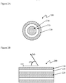
- the light diffusing optical fiber 100 generally comprises a core 110 , which further comprises a scattering region.
- the scattering region may comprise gas filled voids, such as shown in U.S. Appl. Ser. Nos. 12/950,045 , 13/097,208 , and 13/269,055 , or may comprise the inclusion of particles, such as micro- or nanoparticles of ceramic materials, into the fiber core.
- the gas filled voids may occur throughout the core, may occur near the interface of the core and cladding 120 , or may occur as an annular ring within the core.
- the gas filled voids may be arranged in a random or organized pattern and may run parallel to the length of the fiber or may be helical (i.e., rotating along the long axis of the fiber).
- the scattering region may comprise a large number of gas filled voids, for example more than 50, more than 100, or more than 200 voids in the cross section of the fiber.
- the gas filled voids may contain, for example, SO 2 , Kr, Ar, CO 2 , N 2 , O 2 , or mixtures thereof.
- the cross-sectional size (e.g., diameter) of the voids may be from about 10 nm to about 10 ⁇ m and the length may vary from about 1 ⁇ m to about 50 m.
- the cross sectional size of the voids is about 10 nm, 20 nm, 30 nm, 40 nm, 50 nm, 60 nm, 70 nm, 80 nm, 90 nm, 100 nm, 120 nm, 140 nm, 160 nm, 180 nm, 200 nm, 250 nm, 300 nm, 400 nm, 500 nm, 600 nm, 700 nm, 800 nm, 1 ⁇ m, 2 ⁇ m, 3 ⁇ m, 4 ⁇ m, 5 ⁇ m, 6 ⁇ m, 7 ⁇ m, 8 ⁇ m, 9 ⁇ m, or 10 ⁇ m.
- the length of the voids is about 1 ⁇ m, 2 ⁇ m, 3 ⁇ m, 4 ⁇ m, 5 ⁇ m, 6 ⁇ m, 7 ⁇ m, 8 ⁇ m, 9 ⁇ m, 10 ⁇ m, 20 ⁇ m, 30 ⁇ m, 40 ⁇ m, 50 ⁇ m, 60 ⁇ m, 70 ⁇ m, 80 ⁇ m, 90 ⁇ m, 100 ⁇ m, 200 ⁇ m, 300 ⁇ m, 400 ⁇ m, 500 ⁇ m, 600 ⁇ m, 700 ⁇ m, 800 ⁇ m, 900 ⁇ m, 1000 ⁇ m, 5 mm, 10 mm, 50 mm, 100 mm, 500 mm, 1 m, 5 m, 10 m, 20 m, or 50 m.
- the core portion 110 comprises silica-based glass and has an index of refraction, n.
- the index of refraction for the core is about 1.458.
- the core portion 110 may have a radius of from about 10 ⁇ m to about 600 ⁇ m. In some embodiment the radius of the core is from about 30 ⁇ m to about 400 ⁇ m. In other embodiments, the radius of the core is about 125 ⁇ m to about 300 ⁇ m.
- the radius of the core is about 50 ⁇ m, 60 ⁇ m, 70 ⁇ m, 80 ⁇ m, 90 ⁇ m, 100 ⁇ m, 120 ⁇ m, 140 ⁇ m, 160 ⁇ m, 180 ⁇ m, 200 ⁇ m, 220 ⁇ m, 240 ⁇ m, or 250 ⁇ m.
- the voids in the core 110 are utilized to scatter light propagating in the core of the light diffusing optical fiber 100 such that the light is directed radially outward from the core portion 110 , thereby illuminating the light diffusing optical fiber and the space surrounding the light diffusing optical fiber.
- the scatter-induced attenuation may be increased through increasing the concentration of voids, positioning voids throughout the fiber, or in cases where the voids are limited to an annular ring, increasing the width of the annulus comprising the voids will also increase the scattering-induced attenuation for the same density of voids.
- the scattering-induced attenuation may also be increased by varying the pitch of the helical voids over the length of the fiber.
- the pitch of the helical voids refers to the inverse of the number times the helical voids are wrapped or rotated around the long axis of the fiber per unit length.
- the light diffusing optical fiber 100 may further comprise a cladding 120 which surrounds and is in direct contact with the core portion 110.
- the cladding 120 may be formed from a material which has a low refractive index in order to increase the numerical aperture (NA) of the light diffusing optical fiber 100.
- the cladding has a refractive index contrast (as compared to the core) of less than about 1.415.
- the numerical aperture of the fiber may be greater than about 0.3, and in some embodiments greater than about 0.4.
- the cladding 120 comprises a low index polymeric material such as UV or thermally curable fluoroacrylate, such as PC452 available from SSCP Co.
- the cladding comprises a urethane acrylate, such as CPC6, manufactured by DSM Desotech, Elgin, Ill.
- the cladding 120 comprises a silica glass which is down-doped with a down-dopant, such as, for example, fluorine.
- the cladding comprises a high modulus coating.
- the cladding 120 generally has an index of refraction which is less than the index of refraction of the core portion 110.
- the cladding 120 is a low index polymer cladding with a relative refractive index that is negative relative to silica glass.
- the relative refractive index of the cladding may be less than about -0.5% and in some embodiments less than -1%.
- the cladding 120 generally extends from the outer radius of the core portion 110.
- the radial width of the cladding is greater than about 10 ⁇ m, greater than about 20 ⁇ m, greater than about 50 ⁇ m or greater than about 70 ⁇ m.
- the cladding has a thickness of about 10 ⁇ m, 20 ⁇ m, 30 ⁇ m, 40 ⁇ m, 50 ⁇ m, 60 ⁇ m, 70 ⁇ m, 80 ⁇ m, 90 ⁇ m, or 100 ⁇ m.
- the light diffusing fiber may also comprise a clear layer of secondary coating typical for all optical fibers for mechanical handling.
- the scattering layer will be on top of the secondary coating.
- the secondary coating layer and scattering layer may be combined, depending on how fiber is manufactured. For example, if the scattering layer is applied after initial draw of the fiber, for handling issues it may be necessary to apply a clear secondary coating with a second step being directed to application of the scattering layer and phosphor. This process is similar to postdraw ink application for optical fibers. However, it can be combined in one step in the draw, and in this case secondary coating is not needed and the scattering layer may be applied directly on top of the cladding.
- the light diffusing optical fiber 100 further comprises a scattering layer 130 which surrounds and is in direct contact with the cladding 120.
- the scattering layer may comprise a polymer coating.
- the polymer coating may comprise be any liquid polymer or prepolymer material into which the scattering agent could be added and in which the blend may be applied to the fiber as a liquid and then converted to a solid after application to the fiber.
- the scattering layer 130 comprises a polymer coating such as an acrylate-based, such as CPC6, manufactured by DSM Desotech, Elgin, Ill, or silicone-based polymer further comprising a scattering material.
- the cladding 120 comprises a low index polymeric material such as UV or thermally curable fluoroacrylate, such as PC452 available from SSCP Co. Ltd 403-2, Moknae, Ansan, Kyunggi, Korea.
- the cladding comprises a high modulus coating.
- the scattering layer 130 may be utilized to enhance the distribution and/or the nature of the light emitted radially from the core portion 110 and passed through the cladding 120.
- the scattering material may comprise nano- or microparticles with an average diameter of from about 200 nm to about 10 ⁇ m. In some embodiments, the average diameter of the particles is about 200 nm, 300 nm, 400 nm, 500 nm, 600 nm, 700 nm, 800 nm, 900 nm, 1 ⁇ m, 2 ⁇ m, 3 ⁇ m, 4 ⁇ m, 5 ⁇ m, 6 ⁇ m, 7 ⁇ m, 8 ⁇ m, 9 ⁇ m, or 10 ⁇ m.
- the concentration of the scattering particles may vary along the length of the fiber or may be constant and may be a weight percent sufficient to provide even scattering of the light while limiting overall attenuation.
- the weight percentage of the scattering particles in the scattering layer comprises about 1%, 2%, 3%, 4%, 5%, 6%, 7%, 8%, 9%, 10%, 11%, 12%, 13%, 14%, 15%, 16%, 17%, 18%, 19%, 20%, 25%, 30%, 35%, 40%, 45%, or 50%.
- the scattering layer comprises small particles of a scattering material which comprise a metal oxides or other high refractive index material, such as TiO 2 , ZnO, SiO 2 , or Zr.
- the scattering material may also comprise micro- or nanosized particles or voids of law refractive index, such as gas bubbles.
- the scattering layer generally extends from the outer radius of the cladding 120.
- the radial width of the scattering layer is greater than about 1 ⁇ m, 2 ⁇ m, 3 ⁇ m, 4 ⁇ m, 5 ⁇ m, 6 ⁇ m, 7 ⁇ m, 8 ⁇ m, 9 ⁇ m, 10 ⁇ m, 20 ⁇ m, 30 ⁇ m, 40 ⁇ m, 50 ⁇ m, 60 ⁇ m, 70 ⁇ m, 80 ⁇ m, 90 ⁇ m, or 100 ⁇ m.
- the scattering material may contain TiO 2 -based particles, such as a white ink, which provides for an angle independent distribution of light scattered from the core portion 110 of the light diffusing optical fiber 100.
- the scattering particles comprise a sublayer within the scattering layer.
- the particle sublayer may have a thickness of about 1 ⁇ m to about 5 ⁇ m.
- the thickness of the particle layer and/or the concentration of the particles in the scattering layer may be varied along the axial length of the fiber so as to provide more uniform variation in the intensity of light scattered from the light diffusing optical fiber 100 at large angles (i.e., angles greater than about 15 degrees).
- the light diffusing optical fiber 100 further comprises a phosphor layer 140 which surrounds and is in direct contact with the scattering layer 130.
- the fluorescent or phosphorescent material in the phosphor layer may comprise any organic or inorganic fluorescent or phosphorescent material, but in some embodiments may be an inorganic material.
- the phosphor layer may comprise CeYAG, NdYAG, quantum dots, nanoparticles, metal-enhanced fluorescence of organic fluorophores, etc.
- the phosphor layer may comprise a polymer coating.
- the polymer coating may comprise be any liquid polymer or prepolymer material into which the fluorescent or phosphorescent material could be added and in which the blend may be applied to the fiber as a liquid and then converted to a solid after application to the fiber.
- the phosphor layer 140 comprises a polymer coating such as an acrylate-based or silicone based polymer (e.g., CPC6 secondary coating) further comprising a fluorescent or phosphorescent material that converts light scattered from the core portion 110 to a longer wavelength of light.
- the fluorescent or phosphorescent material into standard UV curable acrylate based optical fiber coatings, such as Coming's standard CPC6 secondary optical fiber coating.
- standard UV curable acrylate based optical fiber coatings such as Coming's standard CPC6 secondary optical fiber coating.
- a concentrate was first made by mixing 30% by weight of the fluorescent or phosphorescent agent into DSM 950-111 secondary CPC6 optical fiber coating and then passing the mix over a 3 roll mill. These concentrates were then either applied directly as coatings or were further diluted with DSM 950-111 to give the desired fluorescent or phosphorescent effect.
- white light can be emitted from the light diffusing optical fiber by coupling the light diffusing optical fiber 100 with a fluorescent or phosphorescent material in the phosphor layer 140 to a higher energy (lower wavelength) light source, such as a UV or near UV light source emitting at 405 nm or 445 nm.
- a higher energy (lower wavelength) light source such as a UV or near UV light source emitting at 405 nm or 445 nm.
- the diode laser The UV light from the light source that is scattered from the core portion 110 causes the material in the phosphor layer to fluoresce or phosphoresce such that the combination of UV light and emitted wavelengths produce a white light emission from the light diffusing optical fiber 100.
- the source light is from about 300-550 nm, or about 300, 350, 400, 450, 500, or 550 nm.
- unscattered light propagates down the light diffusing fiber 100 from the source in the direction shown by arrow 150.
- Scattered light is shown exiting the light diffusing fiber as arrow 160 at an angle 170 , which describes angular difference between the direction of the fiber and the direction of the scattered light when it leaves light diffusing fiber 100.
- the UV-visible spectrum of the light diffusing fiber 100 is independent of angle 170.
- the intensities of the spectra when angle 170 is 15° and 150° are within ⁇ 30% as measured at the peak wavelength. In some embodiments, the intensities of the spectra when angle 170 is 15° and 150° are within ⁇ 20%, ⁇ 15%, ⁇ 10%, or ⁇ 5% as measured at the peak wavelength.
- the output of the light diffusing fiber comprises a combination of the scattered incident UV light and the scattered fluorescent or phosphorescent light from the phosphor material to produce a combined light that has the optical property of appearing white.
- the combined light has an x coordinate from about 0.15 to about 0.25 and y coordinate of from about 0.20 to about 0.30 when measured on the x- and y-axes of the CIE 1931 x, y chromacity space ( T. Smith and J. Guild, The C.I.E. Colorimetric Standards and Their Use, 33 TRANS. OP. Soc. 73-134 (1931 )) (see Figure 7 ).
- the combined light has an x coordinate from about 0.18 to about 0.23, or about 0.15, 0.16, 0.17, 0.18, 0.19, 0.20, 0.21, 0.22, 0.23, 0.24, or 0.25 on the CIE 1931 x, y chromacity space. In some embodiments, the combined light has a y coordinate from about 0.23 to about 0.27, or about 0.20, 0.21, 0.22, 0.23, 0.24, 0.25, 0.26, 0.27, 0.28, 0.29, or 0.30 on the CIE 1931 x, y chromacity space.
- the values of the x and y coordinates of the CIE 1931 x, y chromacity space do not vary more than ⁇ 30% with angle 170 when angle 170 is from about 10° to about 170°. In some embodiments, the values of the x and y coordinates of the CIE 1931 x, y chromacity space at angles 170 of 15° and 150° are within ⁇ 30%, ⁇ 25%, ⁇ 20%, ⁇ 15%, ⁇ 10%, or ⁇ 5% of each other.
- the light diffusing optical fibers will generally have a length from about 100 m to about 0.15 m. In some embodiments, the light diffusing optical fibers will generally have a length of about 100 m, 75 m, 50 m, 40 m, 30 m, 20 m, 10 m, 9 m, 8 m, 7 m, 6 m, 5 m, 4 m, 3 m, 2 m, 1 m, 0.75 m, 0.5 m, 0.25 m, 0.15 m, or 0.1 m.
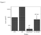
- the light diffusing optical fibers described herein have a scattering induced attenuation loss of greater than about 0.2 dB/m at a wavelength of 550 nm.
- the scattering induced attenuation loss may be greater than about 0.5 dB/m, 0.6 dB/m, 0.7 dB/m, 0.8 dB/m, 0.9 dB/m, 1 dB/m, 1.2 dB/m, 1.4 dB/m, 1.6 dB/m, 1.8 dB/m, 2.0 dB/m, 2.5 dB/m, 3.0 dB/m, 3.5 dB/m, or 4 dB/m, 5 dB/m, 6 dB/m, 7 dB/m, 8 dB/m, 9 dB/m, 10 dB/m, 20 dB/m, 30 dB/m, 40 dB/m, or 50 dB/
- the light diffusing fiber can be constructed to produce uniform illumination along the entire length of the fiber or uniform illumination along a segment of the fiber which is less than the entire length of the fiber.
- uniform illumination means that the intensity of light emitted from the light diffusing fiber does not vary by more than 25% over the specified length.
- the core 110 can be made by any number of methods which incorporate voids or particles into the glass fiber.
- methods for forming an optical fiber preform with voids are described in, for example, U.S. Patent Appl. Ser. No. 11/583,098 . Additional methods of forming voids may be found in, for example, U.S. Appl. Ser. Nos. 12/950,045 , 13/097,208 , and 13/269,055 .
- the optical fiber is drawn from an optical fiber preform with a fiber take-up system and exits the draw furnace along a substantially vertical pathway.
- the fiber is rotated as it drawn to produce helical voids along the long axis of the fiber.
- a non-contact flaw detector may be used to examine the optical fiber for damage and/or flaws that may have occurred during the manufacture of the optical fiber. Thereafter, the diameter of the optical fiber may be measured with non-contact sensor.
- the optical fiber may optionally be drawn through a cooling system which cools the optical fiber prior to the coatings being applied to the optical fiber.
- the optical fiber After the optical fiber exits the draw furnace or optional cooling system, the optical fiber enters at least one coating system where one or more polymer layers (i.e., the polymeric cladding material, the scattering layer, and/or the phosphor layer) are applied to the optical fiber.
- the diameter of the optical fiber may be measured with non-contact sensor.
- a non-contact flaw detector is used to examine the optical fiber for damage and/or flaws in the coating that may have occurred during the manufacture of the optical fiber.
- Another aspect comprises a light diffusing fiber with high efficiencies of light extraction at wavelengths where the fiber cladding has high absorptions, such as below 450 nm.
- LDF for UV wavelengths helps to extend the range of applications for photoreactors, water/air purification, acrylate polymerizations and related.
- Embodiments herein improve the efficiency of the light extraction from LDF, which is normally trapped in the high index secondary coating.
- One notable use of the LDF fiber at this wavelength would be the ability to place light in remote, small, and difficult to access locations for curing UV materials.
- scattering centers are added to the fiber as a scattering layer so that the light is scattered from the scattering coating without significant propagation. This allows for an efficient LDF even at wavelengths where the coating does absorb light.
- the low index glass cladding may be replaced with low index F/B co-doped glass cladding. This type of cladding doesn't give as high an NA as in the case of a low index polymer used as a cladding, but is high enough for a wide range of applications.
- the light diffusing optical fiber 200 generally comprises a core 210 , which further comprises a scattering region.
- the scattering region may comprise gas filled voids, such as shown in U.S. Appl. Ser. Nos. 12/950,045 , 13/097,208 , and 13/269,055 , or may comprise the inclusion of particles, such as micro- or nanoparticles, into the fiber core.
- the gas filled voids may occur throughout the core, may occur near the interface of the core and cladding 220 , or may occur as an annular ring within the core.
- the gas filled voids may be arranged in a random or organized pattern and may run parallel to the length of the fiber or may be helical (i.e., rotating along the long axis of the fiber).
- the scattering region may comprise a large number of gas filled voids, for example more than 50, more than 100, or more than 200 voids in the cross section of the fiber.
- the gas filled voids may contain, for example, SO 2 , Kr, Ar, CO 2 , N 2 , O 2 , or mixtures thereof.
- the cross-sectional size (e.g., diameter) of the voids may be from about 10 nm to about 10 ⁇ m and the length may vary from about 1 ⁇ m to about 50 m.
- the cross sectional size of the voids is about 10 nm, 20 nm, 30 nm, 40 nm, 50 nm, 60 nm, 70 nm, 80 nm, 90 nm, 100 nm, 120 nm, 140 nm, 160 nm, 180 nm, 200 nm, 250 nm, 300 nm, 400 nm, 500 nm, 600 nm, 700 nm, 800 nm, 1 ⁇ m, 2 ⁇ m, 3 ⁇ m, 4 ⁇ m, 5 ⁇ m, 6 ⁇ m, 7 ⁇ m, 8 ⁇ m, 9 ⁇ m, or 10 ⁇ m.
- the length of the voids is about 1 ⁇ m, 2 ⁇ m, 3 ⁇ m, 4 ⁇ m, 5 ⁇ m, 6 ⁇ m, 7 ⁇ m, 8 ⁇ m, 9 ⁇ m, 10 ⁇ m, 20 ⁇ m, 30 ⁇ m, 40 ⁇ m, 50 ⁇ m, 60 ⁇ m, 70 ⁇ m, 80 ⁇ m, 90 ⁇ m, 100 ⁇ m, 200 ⁇ m, 300 ⁇ m, 400 ⁇ m, 500 ⁇ m, 600 ⁇ m, 700 ⁇ m, 800 ⁇ m, 900 ⁇ m, 1000 ⁇ m, 5 mm, 10 mm, 50 mm, 100 mm, 500 mm, 1 m, 5 m, 10 m, 20 m, or 50 m.
- the core portion 210 comprises silica-based glass and has an index of refraction, n.
- the index of refraction for the core is about 1.458.
- the core portion 210 may have a radius of from about 10 ⁇ m to about 600 ⁇ m. In some embodiment the radius of the core is from about 30 ⁇ m to about 400 ⁇ m. In other embodiments, the radius of the core is from about 125 ⁇ m to about 300 ⁇ m.
- the radius of the core is about 50 ⁇ m, 60 ⁇ m, 70 ⁇ m, 80 ⁇ m, 90 ⁇ m, 100 ⁇ m, 120 ⁇ m, 140 ⁇ m, 160 ⁇ m, 180 ⁇ m, 200 ⁇ m, 220 ⁇ m, 240 ⁇ m, or 250 ⁇ m.
- the voids in the core 210 are utilized to scatter light propagating in the core of the light diffusing optical fiber 200 such that the light is directed radially outward from the core portion 210 , thereby illuminating the light diffusing optical fiber and the space surrounding the light diffusing optical fiber.
- the scatter-induced attenuation may be increased through increasing the concentration of voids, positioning voids through out the fiber, or in cases where the voids are limited to an annular ring, increasing the width of the annulus comprising the voids will also increase the scattering-induced attenuation for the same density of voids.
- the scattering-induced attenuation may also be increased by varying the pitch of the helical voids over the length of the fiber.
- the pitch of the helical voids refers to the inverse of the number times the helical voids are wrapped or rotated around the long axis of the fiber per unit length.
- the light diffusing optical fiber 200 may further comprise a cladding 220 which surrounds and is in direct contact with the core portion 210.
- the cladding comprises a fluorine and boron co-doped glass.
- the cladding comprises a polymer.
- the cladding 220 may be formed from a material which has a low refractive index in order to increase the numerical aperture (NA) of the light diffusing optical fiber 200.
- the cladding has a refractive index contrast (as compared to the core) of less than about 1.415.
- the numerical aperture of the fiber may be greater than about 0.3, and in some embodiments, greater than about 0.4.
- the cladding 220 comprises a low index polymeric material such as UV or thermally curable fluoroacrylate, such as PC452 available from SSCP Co. Ltd 403-2, Moknae, Ansan, Kyunggi, Korea, or silicone.
- the cladding comprises a urethane acrylate, such as CPC6, manufactured by DSM Desotech, Elgin, Ill.
- the cladding 220 may be formed from silica glass which is down-doped with a down-dopant, such as, for example, fluorine and boron.
- the cladding 220 generally has an index of refraction which is less than the index of refraction of the core portion 210.
- the cladding 220 is a low index polymer cladding with a relative refractive index that is negative relative to silica glass.
- the relative refractive index of the cladding may be less than about -0.5% and in some embodiments less than -1%.
- the cladding 220 generally extends from the outer radius of the core portion 210.
- the radial width of the cladding is greater than about 10 ⁇ m, greater than about 20 ⁇ m, greater than about 50 ⁇ m or greater than about 70 ⁇ m.
- the cladding has a thickness of about 10 ⁇ m, 20 ⁇ m, 30 ⁇ m, 40 ⁇ m, 50 ⁇ m, 60 ⁇ m, 70 ⁇ m, 80 ⁇ m, 90 ⁇ m, or 100 ⁇ m.
- the light diffusing fiber may also comprise a clear layer of secondary coating typical for mechanical handling.
- a clear layer of secondary coating typical for mechanical handling.
- the scattering layer will be on top of the secondary coating.
- the secondary coating layer and scattering layer may be combined, depending on how fiber is manufactured. For example, if the scattering layer is applied after initial draw of the fiber, for handling issues it may be necessary to apply a clear secondary coating with a second step being directed to application of the scattering layer and phosphor. This process is similar to postdraw ink application for optical fibers. However, it can be combined in one step in the draw, and in this case secondary coating is not needed and the scattering layer may be applied directly on top of the cladding.
- the light diffusing optical fiber 200 further comprises a scattering layer 230 which surrounds and is in direct contact with the cladding 220 .
- the scattering layer 230 comprises a polymer coating such as an acrylate-based or silicone based polymer further comprising a scattering material.
- the coating layer 210 has a constant diameter along the length of the light diffusing optical fiber.
- the scattering layer 230 may be utilized to enhance the distribution and/or the nature of the light emitted radially from the core portion 210 and passed through the cladding 220.
- the scattering layer may comprise a polymer coating.
- the polymer coating may comprise be any liquid polymer or prepolymer material into which the scattering agent could be added and in which the blend may be applied to the fiber as a liquid and then converted to a solid after application to the fiber.
- the scattering layer 230 comprises a polymer coating such as an acrylate-based, such as CPC6, manufactured by DSM Desotech, Elgin, Ill, or silicone-based polymer further comprising a scattering material.
- the cladding 220 comprises a low index polymeric material such as UV or thermally curable fluoroacrylate, such as PC452 available from SSCP Co. Ltd 403-2, Moknae, Ansan, Kyunggi, Korea.
- the cladding comprises a high modulus coating.
- the scattering layer 230 may be utilized to enhance the distribution and/or the nature of the light emitted radially from the core portion 210 and passed through the cladding 220.
- the scattering material may comprise nano- or microparticles with an average diameter of from about 200 nm to about 10 ⁇ m. In some embodiments, the average diameter of the particles is about 200 nm, 300 nm, 400 nm, 500 nm, 600 nm, 700 nm, 800 nm, 900 nm, 1 ⁇ m, 2 ⁇ m, 3 ⁇ m, 4 ⁇ m, 5 ⁇ m, 6 ⁇ m, 7 ⁇ m, 8 ⁇ m, 9 ⁇ m, or 10 ⁇ m.
- the concentration of the scattering particles may vary along the length of the fiber or may be constant and may be a weight percent sufficient to provide even scattering of the light while limiting overall attenuation.
- the weight percentage of the scattering particles comprises about 1%, 2%, 3%, 4%, 5%, 6%, 7%, 8%, 9%, 10%, 11%, 12%, 13%, 14%, 15%, 16%, 17%, 18%, 19%, 20%, 25%, 30%, 35%, 40%, 45%, or 50%.
- the scattering layer comprises a scattering material that is not significantly absorbent in the UV region of incident beam.
- the scattering material comprises metal oxides or other materials with low absorbance in the region from about 350 nm to about 420 nm, such as SiO 2 or Zr, or may comprise nano- to microscale voids comprising a gas, such as oxygen, nitrogen, or a noble gas.
- the scattering layer generally extends from the outer radius of the cladding 220. In some embodiments described herein, the radial width of the scattering layer is greater than about 10 ⁇ m, 20 ⁇ m, 30 ⁇ m, 40 ⁇ m, 50 ⁇ m, 60 ⁇ m, 70 ⁇ m, 80 ⁇ m, 90 ⁇ m, or 100 ⁇ m.
- the scattering material may contain SiO 2 -based particles, which provides for an angle independent distribution of light scattered from the core portion 210 of the light diffusing optical fiber 200.
- the particles comprise a layer within the scattering layer.
- the particle layer may have a thickness of about 1 ⁇ m to about 5 ⁇ m.
- the thickness of the scattering layer may be varied along the axial length of the fiber so as to provide more uniform variation in the intensity of light scattered from the light diffusing optical fiber 200 at large angles (i.e., angles greater than about 15 degrees).
- unscattered light propagates down the light diffusing fiber 200 from the source in the direction shown by arrow 250.
- Scattered light is shown exiting the light diffusing fiber as arrow 260 at an angle 270 , which describes angular difference between the direction of the fiber and the direction of the scattered light when it leaves light diffusing fiber 200.
- the UV-visible spectrum of the light diffusing fiber 200 is independent of angle 270.
- the intensities of the spectra when angle 270 is 15° and 150° are within ⁇ 30% as measured at the peak wavelength. In some embodiments, the intensities of the spectra when angle 270 is 15° and 150° are within ⁇ 20%, ⁇ 15%, ⁇ 10%, or ⁇ 5% as measured at the peak wavelength.
- the light diffusing optical fibers will generally have a length from about 100 m to about 0.15 m. In some embodiments, the light diffusing optical fibers will generally have a length of about 100 m, 75 m, 50 m, 40 m, 30 m, 20 m, 10 m, 9 m, 8 m, 7 m, 6 m, 5 m, 4 m, 3 m, 2 m, 1 m, 0.75 m, 0.5 m, 0.25 m, 0.15 m, or 0.1 m.
- the light diffusing optical fibers described herein have a scattering induced attenuation loss of greater than about 0.2 dB/m at a wavelength of 300 nm, 325 nm, 350 nm, 375 nm, 400 nm, 425 nm, or 450 nm.
- the scattering induced attenuation loss may be greater than about 0.5 dB/m, 0.6 dB/m, 0.7 dB/m, 0.8 dB/m, 0.9 dB/m, 1 dB/m, 1.2 dB/m, 1.4 dB/m, 1.6 dB/m, 1.8 dB/m, 2.0 dB/m, 2.5 dB/m, 3.0 dB/m, 3.5 dB/m, 4 dB/m, 5 dB/m, 6 dB/m, 7 dB/m, 8 dB/m, 9 dB/m, 10 dB/m, 20 dB/m, 30 dB/m, 40 dB/m, or 50 dB/m at 300 nm, 325 nm, 350 nm, 375 nm, 400 nm, 425 nm, or 450 nm.
- the light diffusing fiber may be constructed to produce uniform illumination along the entire length of the fiber or uniform illumination along a segment of the fiber which is less than the entire length of the fiber.
- uniform illumination means that the intensity of light emitted from the light diffusing fiber does not vary by more than 25% over the specified length.
- the core 210 can be made by any number of methods which incorporate voids are particles into the glass fiber.
- methods for forming an optical fiber preform with voids are described in, for example, U.S. Patent Appl. Ser. No. 11/583,098 . Additional methods of forming voids may be found in, for example, U.S. Appl. Ser. Nos. 12/950,045 , 13/097,208 , and 13/269,055 .
- the optical fiber is drawn from an optical fiber preform with a fiber take-up system and exits the draw furnace along a substantially vertical pathway.
- the fiber is rotated as it drawn to produce helical voids along the long axis of the fiber.
- a non-contact flaw detector may be used to examine the optical fiber for damage and/or flaws that may have occurred during the manufacture of the optical fiber. Thereafter, the diameter of the optical fiber may be measured with non-contact sensor.
- the optical fiber may optionally be drawn through a cooling system which cools the optical fiber prior to the coatings being applied to the optical fiber.
- the optical fiber After the optical fiber exits the draw furnace or optional cooling system, the optical fiber enters at least one coating system where one or more polymer layers (i.e., the polymeric cladding material and/or the scattering layer) are applied to the optical fiber.
- the diameter of the optical fiber may be measured with non-contact sensor.
- a non-contact flaw detector is used to examine the optical fiber for damage and/or flaws in the coating that may have occurred during the manufacture of the optical fiber.
- Option 1 - A fiber comprising a silica core, a polymer cladding, a scattering layer, and a phosphor layer.
- the scattering layer comprised silica particles in a polymer and the phosphor layer comprised CeYAG in a polymer.
- the refractive index of the polymer cladding was 1.55, and silica was ⁇ 1.46, so with the significant index mismatch and small size of silica particles ( ⁇ 1 ⁇ m), it was posited that it may be possible to achieve uniform scattering diagram as a function of angle relative to incident angle.
- Option 2 - A fiber comprising a silica core, a polymer cladding, and a single layer comprising both the phosphor layer and the scattering medium.
- CeYAG particles have a refractive index of about 1.8, and as such have a significant mismatch with polymer cladding ( ⁇ 1.55). But since CeYAG the particles used were large ( ⁇ 3-4 ⁇ m), it was assumed that they would not produce significant scattering.
- Option 3 - A fiber comprising a silica core, a polymer cladding, a scattering layer, and a phosphor layer.
- the scattering layer uses high efficient scatterers, such as white ink (TiO 2 based filled polymer).
- TiO 2 has high refractive index ( ⁇ 2.5), so it may be a more efficient scatterer than SiO 2 particles.
- TiO 2 absorbs light at wavelength ⁇ 400 nm and is less suitable for UV light applications.
- each layer and concentration of the dopant was modified to obtain optimum spectrum and angular dependence.
- Figures 1A and 1B are shown a scattering layer and layer doped with phosphor particles. This design was used for white color fibers.
- Figures 2A and 2B are shown a fiber design for UV emission with a secondary coating doped with scattering particles for uniform angular dependence.
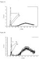
- the scattering emission spectra of various fibers are shown in Figures 3A-3D .
- the incident light had a wavelength of 445 nm and the silica fiber used was a random airline fiber.
- Figures 3A-3C a 160 um-thick single layer of 35 wt. % CeYAG with no scattering material ( Figure 3A ), a 800 um-thick single layer of 35 wt. % CeYAG with no scattering material ( Figure 3B ), and a 160 um-thick single layer of 20 wt.
- Figure 3D shows a number of spectra arising from a fiber comprising a scattering layer comprising TiO 2 particles (4 ⁇ m-thick layer) plus a 160 ⁇ m-thick layer of 35 wt. % CeYAG as a function of angle.
- a scattering layer comprising TiO 2 particles (4 ⁇ m-thick layer) plus a 160 ⁇ m-thick layer of 35 wt. % CeYAG as a function of angle.
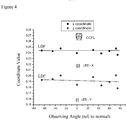
- Figure 4 shows a color coordinated comparison using CIE 1931 x, y chromaticity space values for an embodiment (comprising a silica core, polymer cladding, scattering layer (4 ⁇ m-thick layer of TiO 2 ) and phosphor layer (160 ⁇ m-thick layer of 35 wt. % CeYAG)) is compared to a white LED (which also uses CeYAG in combination with a 460 nm blue LED to obtain white light) and CCFL.
- the color coordinates of the light diffusing fiber place the color output well within the region of what is considered white light (see Figure 7 ). Further, as can be seen from the chart, the color is independent of viewing angle.
- Figure 8 shows a light diffusing fiber comprising a random airline core and a standard polymer cladding. As can be seen from the spectrum, the majority of the light is being emitted from the end of the fiber and very little UV light is being scattered.
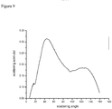
- Figure 9 shows the spectrum of an embodiment of the light diffusing fiber.
- the fiber in Figure 9 comprises a random airline silica core, a polymer cladding and a scattering layer comprising SiO 2 particles with a scattering loss of ⁇ 3 dB/m. As can be seen in Figure 9 , the light is broadly scattered and almost no light is being transmitted out of the end of the fiber.
- the large angle distribution shown in Figure 9 is important for maximum distance coverage from surface of the fiber in application where photochemical reactions take place. Measurements for both Figures 8 and 9 were done in media that matched the refraction index of the fiber core. This means that in media with smaller refractive index, e.g. air, a lot of light from Figure 8 would be trapped in the high index secondary coating. However, if the scattering layer is present, even in air most of the light would escape from the secondary coating very efficiently. Therefore, doping of the secondary coating with silica particles both 1) scatters the light from the secondary coating and 2) also helps to reduce the refractive index of the secondary coating thereby making trapping less efficient.
- media with smaller refractive index e.g. air
- doping of the secondary coating with silica particles both 1) scatters the light from the secondary coating and 2) also helps to reduce the refractive index of the secondary coating thereby making trapping less efficient.
Claims (15)
- Fibre de diffusion de lumière (100) destinée à émettre de la lumière blanche comprenant :a. une âme (110) formée à partir d'un verre à base de silice ;b. un gainage (120) en contact direct avec l'âme (110) ;c. une couche de diffraction (130) en contact direct avec le gainage (120) ; caractérisée en ce que la fibre de diffusion de lumière (100) comprend en outred. une couche de phosphore (140) entourant et en contact direct avec la couche de diffraction (130),sachant que la couleur de la lumière émise, telle que mesurée par l'espace de chromaticité de CIE 1931 x, y, comprend x d'environ 0,20 à environ 0,30 et y d'environ 0,25 à environ 0,35, lorsque ladite fibre de diffusion de lumière est utilisée en combinaison avec une source de lumière de 300 nm à 550 nm.
- La fibre de diffusion de lumière (100) de la revendication 1, sachant que x est d'environ 0,23 à environ 0,28 et y est d'environ 0,28 à environ 0,33.
- La fibre de diffusion de lumière (100) de la revendication 1 ou de la revendication 2, sachant que la couleur de la lumière émise est conforme aux valeurs x, y de l'espace de chromaticité CIE 1931 revendiquées pour tous les angles de vue d'environ 15° à environ 170° par rapport à la direction de la fibre optique de diffusion de lumière (100).
- La fibre de diffusion de lumière (100) selon l'une quelconque des revendications précédentes, sachant que la fibre optique de diffusion de lumière (100) émet de la lumière ayant une intensité le long de la fibre (100) qui ne varie pas de plus d'environ 20 %.
- La fibre de diffusion de lumière (100) selon l'une quelconque des revendications précédentes, sachant que la perte d'atténuation induite par diffraction comprend d'environ 0,1 dB/m à environ 50 dB/m à une longueur d'onde de 550 nm.
- La fibre de diffusion de lumière (100) selon l'une quelconque des revendications précédentes, sachant que l'âme (110) comprend une pluralité de vides distribués aléatoirement.
- La fibre de diffusion de lumière (100) selon l'une quelconque des revendications précédentes, sachant que le gainage (120) comprend un polymère.
- La fibre de diffusion de lumière (100) selon l'une quelconque des revendications précédentes, sachant que la couche de diffraction (130) comprend un polymère.
- La fibre de diffusion de lumière (100) selon l'une quelconque des revendications précédentes, sachant que la couche de diffraction (130) comprend une pluralité de vides distribués aléatoirement ou de microparticules ou nanoparticules d'un matériau de diffraction.
- La fibre de diffusion de lumière (100) de la revendication 9, sachant que les microparticules ou nanoparticules comprennent TiO2 ou SiO2.
- La fibre de diffusion de lumière (100) selon l'une quelconque des revendications précédentes, comprenant en outre un dispositif d'émission de lumière qui émet de la lumière d'une longueur d'onde d'environ 300 nm à environ 450 nm dans l'âme (110) de la fibre de diffusion de lumière (100) .
- La fibre de diffusion de lumière (100) selon l'une quelconque des revendications précédentes, sachant que la couche de phosphore (140) comprend des microparticules ou nanoparticules d'un matériau phosphorescent ou fluorescent inorganique.
- La fibre de diffusion de lumière (100) de la revendication 12, sachant que le matériau phosphorescent ou fluorescent inorganique comprend CeYAG, NdYAG, des boîtes quantiques, ou des nanoparticules.
- La fibre de diffusion de lumière (100) selon l'une quelconque des revendications précédentes, comprenant en outre une couche secondaire intercalée entre le gainage (120) et la couche de diffraction (130).
- Procédé de production de la fibre de diffusion de lumière (100) selon l'une quelconque des revendications précédentes comprenant :a. la formation d'une ébauche de fibre optique comprenant une âme d'ébauche (110) ;b. le tirage de l'ébauche de fibre optique en une fibre optique ;c. le revêtement de la fibre optique avec au moins une couche de gainage (120) ;d. la revêtement de la fibre optique avec au moins une couche de diffraction (130) ; caractérisé en ce que le procédé de production de la fibre de diffusion de lumière (100) comprend en outree. le revêtement de la fibre optique avec au moins une couche de phosphore (140).
Applications Claiming Priority (2)
| Application Number | Priority Date | Filing Date | Title |
|---|---|---|---|
| US201161577156P | 2011-12-19 | 2011-12-19 | |
| PCT/US2012/068853 WO2013095982A1 (fr) | 2011-12-19 | 2012-12-11 | Fibre de diffusion de lumière de couleur blanche uniforme |
Publications (2)
| Publication Number | Publication Date |
|---|---|
| EP2795379A1 EP2795379A1 (fr) | 2014-10-29 |
| EP2795379B1 true EP2795379B1 (fr) | 2020-12-02 |
Family
ID=47430121
Family Applications (1)
| Application Number | Title | Priority Date | Filing Date |
|---|---|---|---|
| EP12806288.2A Active EP2795379B1 (fr) | 2011-12-19 | 2012-12-11 | Fibre de diffusion de lumière de couleur blanche uniforme |
Country Status (4)
| Country | Link |
|---|---|
| US (3) | US9025923B2 (fr) |
| EP (1) | EP2795379B1 (fr) |
| JP (2) | JP2015510603A (fr) |
| WO (1) | WO2013095982A1 (fr) |
Families Citing this family (38)
| Publication number | Priority date | Publication date | Assignee | Title |
|---|---|---|---|---|
| US9093003B2 (en) | 2011-10-11 | 2015-07-28 | Corning Incorporated | Manipulation of color illumination using light diffusing fiber |
| US8620123B2 (en) | 2012-02-13 | 2013-12-31 | Corning Cable Systems Llc | Visual tracer system for fiber optic cable |
| JP2015521294A (ja) | 2012-04-05 | 2015-07-27 | コーニング インコーポレイテッド | ディスプレイコンポーネントを提供するための方法及び装置 |
| US9720157B2 (en) | 2012-08-31 | 2017-08-01 | Corning Incorporated | Flame retardant light diffusing fiber |
| US8967845B2 (en) | 2013-01-11 | 2015-03-03 | Corning Incorporated | Light diffusing optical fiber bundles, illumination systems including light diffusing optical fiber bundles, and methods of affixing light diffusing optical fiber bundles to polymer optical fibers |
| US9618672B2 (en) | 2013-05-31 | 2017-04-11 | Corning Incorporated | Uniform illumination light diffusing fiber device |
| US20140363134A1 (en) * | 2013-06-10 | 2014-12-11 | Corning Optical Communications LLC | Optical fiber cable assembly comprising optical tracer fiber |
| EP3019897A1 (fr) | 2013-07-11 | 2016-05-18 | Corning Incorporated | Unités d'éclairage ayant une fibre optique de diffusion de lumière |
| US20150144802A1 (en) * | 2013-11-25 | 2015-05-28 | Corning Incorporated | Water purification and water supply system decontamination apparatus |
| US9857515B2 (en) | 2014-07-28 | 2018-01-02 | Corning Incorporated | Side-emitting optical fiber system and assembly with light-emitting jacket members |
| JP2017536571A (ja) * | 2014-10-23 | 2017-12-07 | コーニング インコーポレイテッド | ナノ構造の内側および外側コア領域を有する光拡散型光ファイバ |
| US10379309B2 (en) | 2014-11-18 | 2019-08-13 | Corning Optical Communications LLC | Traceable optical fiber cable and filtered viewing device for enhanced traceability |
| US9851500B2 (en) * | 2015-02-06 | 2017-12-26 | Corning Incorporated | Light-diffusing optical elements having cladding with scattering centers |
| US10222629B2 (en) | 2015-02-06 | 2019-03-05 | Corning Incorporated | Laser light illumination systems with speckle reduction and speckle reduction methods |
| EP3277214B1 (fr) | 2015-03-24 | 2020-12-16 | Corning Incorporated | Dispositif chirurgical d'éclairage ayant une fibre de diffusion de lumière |
| US10154779B2 (en) | 2015-03-25 | 2018-12-18 | Corning Incorporated | Controlled variable length and illumination pattern light diffusing optical fiber |
| US10228526B2 (en) | 2015-03-31 | 2019-03-12 | Corning Optical Communications LLC | Traceable cable with side-emitting optical fiber and method of forming the same |
| US10101553B2 (en) | 2015-05-20 | 2018-10-16 | Corning Optical Communications LLC | Traceable cable with side-emitting optical fiber and method of forming the same |
| WO2017015084A1 (fr) | 2015-07-17 | 2017-01-26 | Corning Optical Communications LLC | Systèmes et procédés pour câbles traçables |
| WO2017015085A1 (fr) | 2015-07-17 | 2017-01-26 | Corning Optical Communications LLC | Systèmes et procédés pour câbles de traçage, et câbles pour de tels systèmes et de tels procédés |
| US10101545B2 (en) | 2015-10-30 | 2018-10-16 | Corning Optical Communications LLC | Traceable cable assembly and connector |
| EP3377606A1 (fr) * | 2015-11-20 | 2018-09-26 | Corning Incorporated | Revêtement de conversion de lumière pour dispositif diffuseur de lumière |
| WO2017087790A1 (fr) | 2015-11-20 | 2017-05-26 | Corning Incorporated | Récipient éclairé pour la croissance d'entités biologiques |
| JP7101115B2 (ja) * | 2015-11-25 | 2022-07-14 | コーニング インコーポレイテッド | 光拡散性光ファイバ用コーティング |
| JP2017161689A (ja) * | 2016-03-09 | 2017-09-14 | アダマンド株式会社 | 光分岐結合器及び該光分岐結合器の製造方法、該光分岐結合器を用いた光源装置並びに発光装置 |
| WO2017176825A1 (fr) | 2016-04-08 | 2017-10-12 | Corning Optical Communications LLC | Ensemble de câble à point d'extrémité traçable |
| US10107983B2 (en) | 2016-04-29 | 2018-10-23 | Corning Optical Communications LLC | Preferential mode coupling for enhanced traceable patch cord performance |
| DE102016111730B3 (de) * | 2016-06-27 | 2017-12-28 | Leica Microsystems Cms Gmbh | Beleuchtungseinrichtung sowie Mikroskop mit einer derartigen Beleuchtungseinrichtung |
| US10222560B2 (en) | 2016-12-21 | 2019-03-05 | Corning Research & Development Corporation | Traceable fiber optic cable assembly with fiber guide and tracing optical fibers for carrying light received from a light launch device |
| US10234614B2 (en) | 2017-01-20 | 2019-03-19 | Corning Research & Development Corporation | Light source assemblies and systems and methods with mode homogenization |
| CN110691941A (zh) * | 2017-03-28 | 2020-01-14 | 康宁公司 | 用于发射白光的光扩散光纤 |
| US10539758B2 (en) | 2017-12-05 | 2020-01-21 | Corning Research & Development Corporation | Traceable fiber optic cable assembly with indication of polarity |
| US10539747B2 (en) | 2017-12-05 | 2020-01-21 | Corning Research & Development Corporation | Bend induced light scattering fiber and cable assemblies and method of making |
| US11536888B2 (en) | 2018-04-02 | 2022-12-27 | Corning Incorporated | Light diffusing device with color conversion and related light system |
| EP3891434A1 (fr) * | 2018-12-04 | 2021-10-13 | Signify Holding B.V. | Système de génération de lumière comprenant un corps luminescent allongé |
| CN113227012A (zh) * | 2018-12-19 | 2021-08-06 | 康宁股份有限公司 | 长的长度的均匀照明光漫射光纤 |
| JP6902523B2 (ja) * | 2018-12-27 | 2021-07-14 | 三菱電線工業株式会社 | 側面発光型光ファイバ |
| JP7395545B2 (ja) * | 2021-09-07 | 2023-12-11 | 三菱電線工業株式会社 | 光拡散ファイバを用いた光デバイス |
Family Cites Families (31)
| Publication number | Priority date | Publication date | Assignee | Title |
|---|---|---|---|---|
| JPS50144450A (fr) * | 1974-05-09 | 1975-11-20 | ||
| JPS5728409U (fr) | 1980-07-25 | 1982-02-15 | ||
| JPS58208708A (ja) | 1982-05-28 | 1983-12-05 | Hitachi Cable Ltd | 漏洩光フアイバ |
| JP2002148442A (ja) | 2000-11-14 | 2002-05-22 | Nichia Chem Ind Ltd | 発光装置 |
| JP2002202415A (ja) * | 2000-12-21 | 2002-07-19 | Three M Innovative Properties Co | 側面発光性光ファイバー |
| US20050074216A1 (en) * | 2000-12-21 | 2005-04-07 | Shinichi Irie | Side-illumination type optical fiber |
| JP4526339B2 (ja) * | 2004-09-15 | 2010-08-18 | シャープ株式会社 | 発光体 |
| US7450806B2 (en) | 2005-11-08 | 2008-11-11 | Corning Incorporated | Microstructured optical fibers and methods |
| JP2007227573A (ja) * | 2006-02-22 | 2007-09-06 | Harison Toshiba Lighting Corp | 発光デバイス |
| JP2007258466A (ja) * | 2006-03-23 | 2007-10-04 | Sumita Optical Glass Inc | 照明装置及び発光装置 |
| CN100383580C (zh) * | 2006-03-23 | 2008-04-23 | 南京邮电大学 | 通体均匀发光光纤及其制备方法 |
| DE102006061164B4 (de) * | 2006-12-22 | 2018-12-27 | Osram Opto Semiconductors Gmbh | Lichtemittierende Vorrichtung |
| JP2008311532A (ja) | 2007-06-15 | 2008-12-25 | Rohm Co Ltd | 白色発光装置及び白色発光装置の形成方法 |
| DE102008009138A1 (de) * | 2008-02-14 | 2009-08-27 | Schott Ag | Seitenemittierende brechwertangepasste Faser |
| US8471283B2 (en) * | 2008-02-25 | 2013-06-25 | Kabushiki Kaisha Toshiba | White LED lamp, backlight, light emitting device, display device and illumination device |
| JP5777108B2 (ja) * | 2008-07-25 | 2015-09-09 | コーニング インコーポレイテッド | 生物学的用途のためのナノ構造光ファイバ照明系および方法 |
| JP5571889B2 (ja) | 2008-08-29 | 2014-08-13 | 株式会社東芝 | 発光装置及び照明装置 |
| US8622625B2 (en) * | 2009-05-29 | 2014-01-07 | Corning Incorporated | Fiber end face void closing method, a connectorized optical fiber assembly, and method of forming same |
| WO2011019665A1 (fr) | 2009-08-12 | 2011-02-17 | Alcon Research, Ltd. | Endo-illumination ophtalmique à phosphore thermo-isolé |
| JP6052779B2 (ja) * | 2009-11-20 | 2016-12-27 | コーニング インコーポレイテッド | 側面発光フォトニック光ファイバーを備えた照明システム及びその製造方法 |
| US8331750B2 (en) * | 2010-02-01 | 2012-12-11 | Enlighting Inc | Optical fibers having a surface light field emulation (s-LiFE) segment and method of making the same |
| US8724942B2 (en) * | 2011-04-26 | 2014-05-13 | Corning Incorporated | Light-coupling optical systems and methods employing light-diffusing optical fiber |
| US9541694B2 (en) * | 2011-04-28 | 2017-01-10 | L.E.S.S. Ltd | Waveguide apparatus for illumination systems |
| US8620125B2 (en) | 2011-04-29 | 2013-12-31 | Corning Incorporated | Light diffusing fibers and methods for making the same |
| US8492448B2 (en) | 2011-10-07 | 2013-07-23 | Corning Incorporated | Systems and methods for performing photoreactions using light-diffusing optical fiber |
| US8805141B2 (en) | 2011-10-07 | 2014-08-12 | Corning Incorporated | Optical fiber illumination systems and methods |
| US9093003B2 (en) * | 2011-10-11 | 2015-07-28 | Corning Incorporated | Manipulation of color illumination using light diffusing fiber |
| WO2013066668A1 (fr) * | 2011-10-31 | 2013-05-10 | Corning Incorporated | Fibre optique de diffusion de lumière comportant couche de protection contre l'ultraviolet (uv) |
| WO2013095981A1 (fr) * | 2011-12-19 | 2013-06-27 | Corning Incorporated | Fibre de diffusion de lumière efficace ultraviolette (uv) uniforme |
| US8967845B2 (en) * | 2013-01-11 | 2015-03-03 | Corning Incorporated | Light diffusing optical fiber bundles, illumination systems including light diffusing optical fiber bundles, and methods of affixing light diffusing optical fiber bundles to polymer optical fibers |
| US8926143B2 (en) * | 2013-03-13 | 2015-01-06 | Corning Incorporated | Light-diffusing elements |
-
2012
- 2012-12-11 EP EP12806288.2A patent/EP2795379B1/fr active Active
- 2012-12-11 JP JP2014549104A patent/JP2015510603A/ja active Pending
- 2012-12-11 WO PCT/US2012/068853 patent/WO2013095982A1/fr active Application Filing
- 2012-12-13 US US13/713,224 patent/US9025923B2/en not_active Ceased
-
2017
- 2017-05-05 US US15/588,031 patent/USRE47288E1/en active Active
-
2018
- 2018-11-05 JP JP2018208006A patent/JP2019061247A/ja active Pending
-
2019
- 2019-01-25 US US16/258,183 patent/USRE48428E1/en active Active
Non-Patent Citations (1)
| Title |
|---|
| None * |
Also Published As
| Publication number | Publication date |
|---|---|
| US20130156391A1 (en) | 2013-06-20 |
| EP2795379A1 (fr) | 2014-10-29 |
| WO2013095982A1 (fr) | 2013-06-27 |
| USRE48428E1 (en) | 2021-02-09 |
| USRE47288E1 (en) | 2019-03-12 |
| US9025923B2 (en) | 2015-05-05 |
| JP2019061247A (ja) | 2019-04-18 |
| JP2015510603A (ja) | 2015-04-09 |
Similar Documents
| Publication | Publication Date | Title |
|---|---|---|
| USRE48428E1 (en) | Uniform white color light diffusing fiber | |
| US10175405B2 (en) | Uniform efficient light diffusing fiber | |
| EP3004730B1 (fr) | Dispositif de fibre de diffusion de lumière pour un éclairement uniforme | |
| US20140218958A1 (en) | Uniform illumination light diffusing fiber | |
| US11059747B2 (en) | Light diffusing optical fibers for emitting white light | |
| US20200257029A1 (en) | Light converting coating for light diffusing device | |
| WO2016133942A1 (fr) | Fibre optique à diffusion de lumière et système d'éclairage à fibre optique | |
| Logunov et al. | Silica nano-structured fiber for illumination | |
| JP2015501443A (ja) | 光拡散ファイバを備えたカラー照明表示パネル | |
| Saito et al. | Bright afterglow illuminator made of phosphorescent material and fluorescent fibers | |
| US11536888B2 (en) | Light diffusing device with color conversion and related light system | |
| JP7408543B2 (ja) | 拡散長さに沿って均一な照明を有する光拡散光ファイバ、および光拡散光ファイバを形成する方法 | |
| US20220050252A1 (en) | Light diffusing multi-fiber design configured for use with uv leds |
Legal Events
| Date | Code | Title | Description |
|---|---|---|---|
| PUAI | Public reference made under article 153(3) epc to a published international application that has entered the european phase |
Free format text: ORIGINAL CODE: 0009012 |
|
| 17P | Request for examination filed |
Effective date: 20140717 |
|
| AK | Designated contracting states |
Kind code of ref document: A1 Designated state(s): AL AT BE BG CH CY CZ DE DK EE ES FI FR GB GR HR HU IE IS IT LI LT LU LV MC MK MT NL NO PL PT RO RS SE SI SK SM TR |
|
| DAX | Request for extension of the european patent (deleted) | ||
| STAA | Information on the status of an ep patent application or granted ep patent |
Free format text: STATUS: EXAMINATION IS IN PROGRESS |
|
| 17Q | First examination report despatched |
Effective date: 20191022 |
|
| GRAP | Despatch of communication of intention to grant a patent |
Free format text: ORIGINAL CODE: EPIDOSNIGR1 |
|
| STAA | Information on the status of an ep patent application or granted ep patent |
Free format text: STATUS: GRANT OF PATENT IS INTENDED |
|
| INTG | Intention to grant announced |
Effective date: 20200624 |
|
| GRAS | Grant fee paid |
Free format text: ORIGINAL CODE: EPIDOSNIGR3 |
|
| GRAA | (expected) grant |
Free format text: ORIGINAL CODE: 0009210 |
|
| STAA | Information on the status of an ep patent application or granted ep patent |
Free format text: STATUS: THE PATENT HAS BEEN GRANTED |
|
| AK | Designated contracting states |
Kind code of ref document: B1 Designated state(s): AL AT BE BG CH CY CZ DE DK EE ES FI FR GB GR HR HU IE IS IT LI LT LU LV MC MK MT NL NO PL PT RO RS SE SI SK SM TR |
|
| REG | Reference to a national code |
Ref country code: GB Ref legal event code: FG4D |
|
| REG | Reference to a national code |
Ref country code: AT Ref legal event code: REF Ref document number: 1341559 Country of ref document: AT Kind code of ref document: T Effective date: 20201215 Ref country code: CH Ref legal event code: EP |
|
| REG | Reference to a national code |
Ref country code: DE Ref legal event code: R096 Ref document number: 602012073530 Country of ref document: DE |
|
| REG | Reference to a national code |
Ref country code: IE Ref legal event code: FG4D |
|
| PG25 | Lapsed in a contracting state [announced via postgrant information from national office to epo] |
Ref country code: RS Free format text: LAPSE BECAUSE OF FAILURE TO SUBMIT A TRANSLATION OF THE DESCRIPTION OR TO PAY THE FEE WITHIN THE PRESCRIBED TIME-LIMIT Effective date: 20201202 Ref country code: FI Free format text: LAPSE BECAUSE OF FAILURE TO SUBMIT A TRANSLATION OF THE DESCRIPTION OR TO PAY THE FEE WITHIN THE PRESCRIBED TIME-LIMIT Effective date: 20201202 Ref country code: NO Free format text: LAPSE BECAUSE OF FAILURE TO SUBMIT A TRANSLATION OF THE DESCRIPTION OR TO PAY THE FEE WITHIN THE PRESCRIBED TIME-LIMIT Effective date: 20210302 Ref country code: GR Free format text: LAPSE BECAUSE OF FAILURE TO SUBMIT A TRANSLATION OF THE DESCRIPTION OR TO PAY THE FEE WITHIN THE PRESCRIBED TIME-LIMIT Effective date: 20210303 |
|
| REG | Reference to a national code |
Ref country code: NL Ref legal event code: MP Effective date: 20201202 |
|
| REG | Reference to a national code |
Ref country code: AT Ref legal event code: MK05 Ref document number: 1341559 Country of ref document: AT Kind code of ref document: T Effective date: 20201202 |
|
| PG25 | Lapsed in a contracting state [announced via postgrant information from national office to epo] |
Ref country code: BG Free format text: LAPSE BECAUSE OF FAILURE TO SUBMIT A TRANSLATION OF THE DESCRIPTION OR TO PAY THE FEE WITHIN THE PRESCRIBED TIME-LIMIT Effective date: 20210302 Ref country code: SE Free format text: LAPSE BECAUSE OF FAILURE TO SUBMIT A TRANSLATION OF THE DESCRIPTION OR TO PAY THE FEE WITHIN THE PRESCRIBED TIME-LIMIT Effective date: 20201202 Ref country code: PL Free format text: LAPSE BECAUSE OF FAILURE TO SUBMIT A TRANSLATION OF THE DESCRIPTION OR TO PAY THE FEE WITHIN THE PRESCRIBED TIME-LIMIT Effective date: 20201202 Ref country code: LV Free format text: LAPSE BECAUSE OF FAILURE TO SUBMIT A TRANSLATION OF THE DESCRIPTION OR TO PAY THE FEE WITHIN THE PRESCRIBED TIME-LIMIT Effective date: 20201202 |
|
| PGFP | Annual fee paid to national office [announced via postgrant information from national office to epo] |
Ref country code: DE Payment date: 20201230 Year of fee payment: 9 |
|
| PG25 | Lapsed in a contracting state [announced via postgrant information from national office to epo] |
Ref country code: NL Free format text: LAPSE BECAUSE OF FAILURE TO SUBMIT A TRANSLATION OF THE DESCRIPTION OR TO PAY THE FEE WITHIN THE PRESCRIBED TIME-LIMIT Effective date: 20201202 Ref country code: HR Free format text: LAPSE BECAUSE OF FAILURE TO SUBMIT A TRANSLATION OF THE DESCRIPTION OR TO PAY THE FEE WITHIN THE PRESCRIBED TIME-LIMIT Effective date: 20201202 |
|
| REG | Reference to a national code |
Ref country code: LT Ref legal event code: MG9D |
|
| PG25 | Lapsed in a contracting state [announced via postgrant information from national office to epo] |
Ref country code: LT Free format text: LAPSE BECAUSE OF FAILURE TO SUBMIT A TRANSLATION OF THE DESCRIPTION OR TO PAY THE FEE WITHIN THE PRESCRIBED TIME-LIMIT Effective date: 20201202 Ref country code: SK Free format text: LAPSE BECAUSE OF FAILURE TO SUBMIT A TRANSLATION OF THE DESCRIPTION OR TO PAY THE FEE WITHIN THE PRESCRIBED TIME-LIMIT Effective date: 20201202 Ref country code: PT Free format text: LAPSE BECAUSE OF FAILURE TO SUBMIT A TRANSLATION OF THE DESCRIPTION OR TO PAY THE FEE WITHIN THE PRESCRIBED TIME-LIMIT Effective date: 20210405 Ref country code: RO Free format text: LAPSE BECAUSE OF FAILURE TO SUBMIT A TRANSLATION OF THE DESCRIPTION OR TO PAY THE FEE WITHIN THE PRESCRIBED TIME-LIMIT Effective date: 20201202 Ref country code: SM Free format text: LAPSE BECAUSE OF FAILURE TO SUBMIT A TRANSLATION OF THE DESCRIPTION OR TO PAY THE FEE WITHIN THE PRESCRIBED TIME-LIMIT Effective date: 20201202 Ref country code: EE Free format text: LAPSE BECAUSE OF FAILURE TO SUBMIT A TRANSLATION OF THE DESCRIPTION OR TO PAY THE FEE WITHIN THE PRESCRIBED TIME-LIMIT Effective date: 20201202 Ref country code: CZ Free format text: LAPSE BECAUSE OF FAILURE TO SUBMIT A TRANSLATION OF THE DESCRIPTION OR TO PAY THE FEE WITHIN THE PRESCRIBED TIME-LIMIT Effective date: 20201202 |
|
| REG | Reference to a national code |
Ref country code: CH Ref legal event code: PL |
|
| PG25 | Lapsed in a contracting state [announced via postgrant information from national office to epo] |
Ref country code: AT Free format text: LAPSE BECAUSE OF FAILURE TO SUBMIT A TRANSLATION OF THE DESCRIPTION OR TO PAY THE FEE WITHIN THE PRESCRIBED TIME-LIMIT Effective date: 20201202 |
|
| REG | Reference to a national code |
Ref country code: DE Ref legal event code: R097 Ref document number: 602012073530 Country of ref document: DE Ref country code: BE Ref legal event code: MM Effective date: 20201231 |
|
| PG25 | Lapsed in a contracting state [announced via postgrant information from national office to epo] |
Ref country code: IS Free format text: LAPSE BECAUSE OF FAILURE TO SUBMIT A TRANSLATION OF THE DESCRIPTION OR TO PAY THE FEE WITHIN THE PRESCRIBED TIME-LIMIT Effective date: 20210402 Ref country code: MC Free format text: LAPSE BECAUSE OF FAILURE TO SUBMIT A TRANSLATION OF THE DESCRIPTION OR TO PAY THE FEE WITHIN THE PRESCRIBED TIME-LIMIT Effective date: 20201202 |
|
| PLBE | No opposition filed within time limit |
Free format text: ORIGINAL CODE: 0009261 |
|
| STAA | Information on the status of an ep patent application or granted ep patent |
Free format text: STATUS: NO OPPOSITION FILED WITHIN TIME LIMIT |
|
| PG25 | Lapsed in a contracting state [announced via postgrant information from national office to epo] |
Ref country code: FR Free format text: LAPSE BECAUSE OF NON-PAYMENT OF DUE FEES Effective date: 20210202 Ref country code: LU Free format text: LAPSE BECAUSE OF NON-PAYMENT OF DUE FEES Effective date: 20201211 Ref country code: AL Free format text: LAPSE BECAUSE OF FAILURE TO SUBMIT A TRANSLATION OF THE DESCRIPTION OR TO PAY THE FEE WITHIN THE PRESCRIBED TIME-LIMIT Effective date: 20201202 Ref country code: IE Free format text: LAPSE BECAUSE OF NON-PAYMENT OF DUE FEES Effective date: 20201211 Ref country code: IT Free format text: LAPSE BECAUSE OF FAILURE TO SUBMIT A TRANSLATION OF THE DESCRIPTION OR TO PAY THE FEE WITHIN THE PRESCRIBED TIME-LIMIT Effective date: 20201202 |
|
| 26N | No opposition filed |
Effective date: 20210903 |
|
| GBPC | Gb: european patent ceased through non-payment of renewal fee |
Effective date: 20210302 |
|
| PG25 | Lapsed in a contracting state [announced via postgrant information from national office to epo] |
Ref country code: ES Free format text: LAPSE BECAUSE OF FAILURE TO SUBMIT A TRANSLATION OF THE DESCRIPTION OR TO PAY THE FEE WITHIN THE PRESCRIBED TIME-LIMIT Effective date: 20201202 Ref country code: CH Free format text: LAPSE BECAUSE OF NON-PAYMENT OF DUE FEES Effective date: 20201231 Ref country code: DK Free format text: LAPSE BECAUSE OF FAILURE TO SUBMIT A TRANSLATION OF THE DESCRIPTION OR TO PAY THE FEE WITHIN THE PRESCRIBED TIME-LIMIT Effective date: 20201202 Ref country code: SI Free format text: LAPSE BECAUSE OF FAILURE TO SUBMIT A TRANSLATION OF THE DESCRIPTION OR TO PAY THE FEE WITHIN THE PRESCRIBED TIME-LIMIT Effective date: 20201202 Ref country code: LI Free format text: LAPSE BECAUSE OF NON-PAYMENT OF DUE FEES Effective date: 20201231 |
|
| PG25 | Lapsed in a contracting state [announced via postgrant information from national office to epo] |
Ref country code: GB Free format text: LAPSE BECAUSE OF NON-PAYMENT OF DUE FEES Effective date: 20210302 |
|
| PG25 | Lapsed in a contracting state [announced via postgrant information from national office to epo] |
Ref country code: IS Free format text: LAPSE BECAUSE OF FAILURE TO SUBMIT A TRANSLATION OF THE DESCRIPTION OR TO PAY THE FEE WITHIN THE PRESCRIBED TIME-LIMIT Effective date: 20210402 Ref country code: TR Free format text: LAPSE BECAUSE OF FAILURE TO SUBMIT A TRANSLATION OF THE DESCRIPTION OR TO PAY THE FEE WITHIN THE PRESCRIBED TIME-LIMIT Effective date: 20201202 Ref country code: MT Free format text: LAPSE BECAUSE OF FAILURE TO SUBMIT A TRANSLATION OF THE DESCRIPTION OR TO PAY THE FEE WITHIN THE PRESCRIBED TIME-LIMIT Effective date: 20201202 Ref country code: CY Free format text: LAPSE BECAUSE OF FAILURE TO SUBMIT A TRANSLATION OF THE DESCRIPTION OR TO PAY THE FEE WITHIN THE PRESCRIBED TIME-LIMIT Effective date: 20201202 |
|
| PG25 | Lapsed in a contracting state [announced via postgrant information from national office to epo] |
Ref country code: MK Free format text: LAPSE BECAUSE OF FAILURE TO SUBMIT A TRANSLATION OF THE DESCRIPTION OR TO PAY THE FEE WITHIN THE PRESCRIBED TIME-LIMIT Effective date: 20201202 |
|
| REG | Reference to a national code |
Ref country code: DE Ref legal event code: R119 Ref document number: 602012073530 Country of ref document: DE |
|
| PG25 | Lapsed in a contracting state [announced via postgrant information from national office to epo] |
Ref country code: BE Free format text: LAPSE BECAUSE OF NON-PAYMENT OF DUE FEES Effective date: 20201231 |
|
| PG25 | Lapsed in a contracting state [announced via postgrant information from national office to epo] |
Ref country code: DE Free format text: LAPSE BECAUSE OF NON-PAYMENT OF DUE FEES Effective date: 20220701 |