EP2794961B1 - Continuous recovery system for electrorefiner system - Google Patents
Continuous recovery system for electrorefiner system Download PDFInfo
- Publication number
- EP2794961B1 EP2794961B1 EP12846804.8A EP12846804A EP2794961B1 EP 2794961 B1 EP2794961 B1 EP 2794961B1 EP 12846804 A EP12846804 A EP 12846804A EP 2794961 B1 EP2794961 B1 EP 2794961B1
- Authority
- EP
- European Patent Office
- Prior art keywords
- section
- trough
- recovery system
- continuous recovery
- furrow portion
- Prior art date
- Legal status (The legal status is an assumption and is not a legal conclusion. Google has not performed a legal analysis and makes no representation as to the accuracy of the status listed.)
- Active
Links
Images


Classifications
-
- B—PERFORMING OPERATIONS; TRANSPORTING
- B65—CONVEYING; PACKING; STORING; HANDLING THIN OR FILAMENTARY MATERIAL
- B65G—TRANSPORT OR STORAGE DEVICES, e.g. CONVEYORS FOR LOADING OR TIPPING, SHOP CONVEYOR SYSTEMS OR PNEUMATIC TUBE CONVEYORS
- B65G19/00—Conveyors comprising an impeller or a series of impellers carried by an endless traction element and arranged to move articles or materials over a supporting surface or underlying material, e.g. endless scraper conveyors
- B65G19/14—Conveyors comprising an impeller or a series of impellers carried by an endless traction element and arranged to move articles or materials over a supporting surface or underlying material, e.g. endless scraper conveyors for moving bulk material in closed conduits, e.g. tubes
-
- C—CHEMISTRY; METALLURGY
- C25—ELECTROLYTIC OR ELECTROPHORETIC PROCESSES; APPARATUS THEREFOR
- C25C—PROCESSES FOR THE ELECTROLYTIC PRODUCTION, RECOVERY OR REFINING OF METALS; APPARATUS THEREFOR
- C25C3/00—Electrolytic production, recovery or refining of metals by electrolysis of melts
- C25C3/34—Electrolytic production, recovery or refining of metals by electrolysis of melts of metals not provided for in groups C25C3/02 - C25C3/32
-
- B—PERFORMING OPERATIONS; TRANSPORTING
- B65—CONVEYING; PACKING; STORING; HANDLING THIN OR FILAMENTARY MATERIAL
- B65G—TRANSPORT OR STORAGE DEVICES, e.g. CONVEYORS FOR LOADING OR TIPPING, SHOP CONVEYOR SYSTEMS OR PNEUMATIC TUBE CONVEYORS
- B65G45/00—Lubricating, cleaning, or clearing devices
- B65G45/10—Cleaning devices
- B65G45/12—Cleaning devices comprising scrapers
- B65G45/14—Moving scrapers
-
- C—CHEMISTRY; METALLURGY
- C25—ELECTROLYTIC OR ELECTROPHORETIC PROCESSES; APPARATUS THEREFOR
- C25C—PROCESSES FOR THE ELECTROLYTIC PRODUCTION, RECOVERY OR REFINING OF METALS; APPARATUS THEREFOR
- C25C7/00—Constructional parts, or assemblies thereof, of cells; Servicing or operating of cells
- C25C7/005—Constructional parts, or assemblies thereof, of cells; Servicing or operating of cells of cells for the electrolysis of melts
-
- C—CHEMISTRY; METALLURGY
- C25—ELECTROLYTIC OR ELECTROPHORETIC PROCESSES; APPARATUS THEREFOR
- C25C—PROCESSES FOR THE ELECTROLYTIC PRODUCTION, RECOVERY OR REFINING OF METALS; APPARATUS THEREFOR
- C25C7/00—Constructional parts, or assemblies thereof, of cells; Servicing or operating of cells
- C25C7/02—Electrodes; Connections thereof
- C25C7/025—Electrodes; Connections thereof used in cells for the electrolysis of melts
Definitions
- the present invention relates to a continuous recovery system according to the claims.
- An electrochemical process may be used to recover metals from an impure feed and/or to extract metals from a metal-oxide.
- a conventional process typically involves dissolving a metal-oxide in an electrolyte followed by electrolytic decomposition or (for insoluble metal oxides) selective electrotransport to reduce the metal-oxide to its corresponding metal.
- Conventional electrochemical processes for reducing metal-oxides to their corresponding metallic state may employ a single step or multiple-step approach.
- a multiple-step approach may be a two-step process that utilizes two separate vessels.
- the extraction of uranium from the uranium oxide of spent nuclear fuels includes an initial step of reducing the uranium oxide with lithium dissolved in a molten LiCl electrolyte so as to produce uranium metal and Li 2 O in a first vessel, wherein the Li 2 O remains dissolved in the molten LiCl electrolyte.
- the process then involves a subsequent step of electrowinning in a second vessel, wherein the dissolved Li 2 O in the molten LiCl is electrolytically decomposed to form oxygen gas and regenerate lithium. Consequently, the resulting uranium metal may be extracted in a subsequent electrorefining process, while the molten LiCl with the regenerated lithium may be recycled for use in the reduction step of another batch.
- a multi-step approach involves a number of engineering complexities, such as issues pertaining to the transfer of molten salt and reductant at high temperatures from one vessel to another.
- the reduction of oxides in molten salts may be thermodynamically constrained depending on the electrolyte-reductant system.
- this thermodynamic constraint will limit the amount of oxides that can be reduced in a given batch. As a result, more frequent transfers of molten electrolyte and reductant will be needed to meet production requirements.
- a single-step approach generally involves immersing a metal oxide in a compatible molten electrolyte together with a cathode and anode.
- the metal oxide which is in electrical contact with the cathode
- the yield of the metallic product is relatively low.
- the metallic product still contains unwanted impurities.
- harvesting the metallic product is relatively difficult, because the electrolytic process is typically stopped and the anode and cathode are removed to allow access to the metallic product. This inefficiency also causes time delays, introduces thermal stresses to structural members, and adds undesired heat to the glovebox environment.
- a continuous recovery system includes a trough having a ridge portion and a furrow portion.
- the furrow portion includes a first section and a second section.
- An inlet pipe and an exit pipe are connected to the trough.
- the inlet pipe includes an outlet opening that opens up to the first section of the furrow portion of the trough.
- the exit pipe includes an entrance opening that opens up to the second section of the furrow portion of the trough.
- a chain extends through the inlet and exit pipes and along the furrow portion of the trough. The chain is in a continuous loop form. A plurality of flights are secured to the chain.
- first, second, third, etc. may be used herein to describe various elements, components, regions, layers and/or sections, these elements, components, regions, layers, and/or sections should not be limited by these terms. These terms are only used to distinguish one element, component, region, layer, or section from another region, layer, or section. Thus, a first element, component, region, layer, or section discussed below could be termed a second element, component, region, layer, or section without departing from the teachings of example embodiments.
- spatially relative terms e.g., "beneath,” “below,” “lower,” “above,” “upper,” and the like
- the spatially relative terms are intended to encompass different orientations of the device in use or operation in addition to the orientation depicted in the figures. For example, if the device in the figures is turned over, elements described as “below” or “beneath” other elements or features would then be oriented “above” the other elements or features. Thus, the term “below” may encompass both an orientation of above and below.
- the device may be otherwise oriented (rotated 90 degrees or at other orientations) and the spatially relative descriptors used herein interpreted accordingly.
- Example embodiments are described herein with reference to cross-sectional illustrations that are schematic illustrations of idealized embodiments (and intermediate structures) of example embodiments. As such, variations from the shapes of the illustrations as a result, for example, of manufacturing techniques and/or tolerances, are to be expected. Thus, example embodiments should not be construed as limited to the shapes of regions illustrated herein but are to include deviations in shapes that result, for example, from manufacturing. For example, an implanted region illustrated as a rectangle will, typically, have rounded or curved features and/or a gradient of implant concentration at its edges rather than a binary change from implanted to non-implanted region.
- a buried region formed by implantation may result in some implantation in the region between the buried region and the surface through which the implantation takes place.
- the regions illustrated in the figures are schematic in nature and their shapes are not intended to illustrate the actual shape of a region of a device and are not intended to limit the scope of example embodiments.
- An electrorefiner system may be used to recover a purified metal (e.g., uranium) from a relatively impure nuclear feed material (e.g., impure uranium feed material).
- the impure nuclear feed material may be a metallic product of an electrolytic oxide reduction system.
- the electrolytic oxide reduction system may be configured to facilitate the reduction of an oxide to its metallic form so as to permit the subsequent recovery of the metal.
- the electrolytic oxide reduction system may be as described in U.S. Application No. 12/978,027, filed December 23, 2010 , "ELECTROLYTIC OXIDE REDUCTION SYSTEM," HDP Ref.: 8564-000228/US, GE Ref.: 24AR246140.
- the electrorefiner system may include a vessel, a plurality of cathode assemblies, a plurality of anode assemblies, a power system, a scraper, and/or a continuous recovery system.
- the electrorefiner system may be as described in U.S. 9150975 , titled “ELECTROREFINER SYSTEM FOR RECOVERING PURIFIED METAL FROM IMPURE NUCLEAR FEED MATERIAL,".
- the power system may be as described in U.S. 8882973 , titled “CATHODE POWER DISTRIBUTION SYSTEM AND METHOD OF USING THE SAME FOR POWER DISTRIBUTION,”.
- the scraper may be as described in U.S.
- electrorefiner system is not limited thereto and may include other components that may not have been specifically identified herein.
- electrorefiner system and/or electrolytic oxide reduction system may be used to perform a method for corium and used nuclear fuel stabilization processing. The method may be as described in U.S. 8968547 , titled “METHOD FOR CORIUM AND USED NUCLEAR FUEL STABILIZATION PROCESSING,”.
- the impure nuclear feed material for the electrorefiner system may be a metallic product of an electrolytic oxide reduction system.
- a plurality of anode and cathode assemblies are immersed in a molten salt electrolyte.
- the molten salt electrolyte may be lithium chloride (LiCl).
- the molten salt electrolyte may be maintained at a temperature of about 650°C (+50°C, -30°C).
- An electrochemical process is carried out such that a reducing potential is generated at the cathode assemblies, which contain the oxide feed material (e.g., metal oxide).
- the cathode reaction may be as follows: MO + 2e - ⁇ M + O 2-
- the oxide ion is converted to oxygen gas.
- the anode shroud of each of the anode assemblies may be used to dilute, cool, and remove the oxygen gas from the electrolytic oxide reduction system during the process.
- the anode reaction may be as follows: O 2- ⁇ 1 ⁇ 2O 2 + 2e -
- the metal oxide may be uranium dioxide (UO 2 ), and the reduction product may be uranium metal.
- UO 2 uranium dioxide
- the reduction product may be uranium metal.
- other types of oxides may also be reduced to their corresponding metals with the electrolytic oxide reduction system.
- the molten salt electrolyte used in the electrolytic oxide reduction system is not particularly limited thereto and may vary depending of the oxide feed material to be reduced.
- the basket containing the metallic product in the electrolytic oxide reduction system is transferred to the electrorefiner system according to the present invention for further processing to obtain a purified metal from the metallic product.
- the metallic product from the electrolytic oxide reduction system will serve as the impure nuclear feed material for the electrorefiner system according to the present invention.
- the basket containing the metallic product is a cathode assembly in the electrolytic oxide reduction system
- the basket containing the metallic product is an anode assembly in the electrorefiner system.
- the electrorefiner system according to the present invention allows for a significantly greater yield of purified metal.
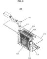
- FIG. 1 is a perspective view of an electrorefiner system including a continuous recovery system according to a non-limiting embodiment of the present invention.
- FIG. 2 is a perspective view of a cross-section of an electrorefiner system including a continuous recovery system according to a non-limiting embodiment of the present invention.
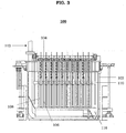
- FIG. 3 is a cross-sectional side view of an electrorefiner system including a continuous recovery system according to a non-limiting embodiment of the present invention.
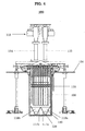
- FIG. 4 is a cross-sectional end view of an electrorefiner system including a continuous recovery system according to a non-limiting embodiment of the present invention.
- the electrorefiner system 100 includes a vessel 102, a plurality of cathode assemblies 104, a plurality of anode assemblies 108, a power system, a scraper 110, and/or a continuous recovery system 112.
- Each of the plurality of cathode assemblies 104 may include a plurality of cathode rods 106.
- the power system may include an electrical feedthrough 132 that extends through the floor structure 134.
- the floor structure 134 may be a glovebox floor of a glovebox. Alternatively, the floor structure 134 may be a support plate of a hot-cell facility.
- the continuous recovery system 112 may include an inlet pipe 113, a trough 116, a turn idler 124, a chain, a plurality of flights 126, an exit pipe 114, and/or a discharge chute 128.
- the continuous recovery system 112 will be described in further detail in connection with FIG. 5 .
- the vessel 102 is configured to maintain a molten salt electrolyte.
- the molten salt electrolyte may be LiCl, a LiCl-KCl eutectic, or another suitable medium.
- the vessel 102 may be situated such that a majority of the vessel 102 is below the floor structure 134. For instance, an upper portion of the vessel 102 may extend above the floor structure 134 through an opening in the floor structure 134. The opening in the floor structure 134 may correspond to the dimensions of the vessel 102.
- the vessel 102 is configured to receive the plurality of cathode assemblies 104 and the plurality of anode assemblies 108.
- the plurality of cathode assemblies 104 are configured to extend into the vessel 102 so as to at least be partially submerged in the molten salt electrolyte. For instance, the dimensions of the plurality of cathode assemblies 104 and/or the vessel 102 may be adjusted such that the majority of the length of the plurality of cathode assemblies 104 is submerged in the molten salt electrolyte in the vessel 102.
- Each cathode assembly 104 may include a plurality of cathode rods 106 having the same orientation and arranged so as to be within the same plane.
- the plurality of anode assemblies 108 may be alternately arranged with the plurality of cathode assemblies 104 such that each anode assembly 108 is flanked by two cathode assemblies 104.
- the plurality of cathode assemblies 104 and anode assemblies 108 may be arranged in parallel.
- Each anode assembly 108 may be configured to hold and immerse an impure uranium feed material in the molten salt electrolyte maintained by the vessel 102.
- the dimensions of the plurality of anode assemblies 108 and/or the vessel 102 may be adjusted such that the majority of the length of the plurality of anode assemblies 108 is submerged in the molten salt electrolyte in the vessel 102.
- the electrorefiner system 100 is illustrated in FIGS. 1-4 as having eleven cathode assemblies 104 and ten anode assemblies 108, it should be understood that the example embodiments herein are not limited thereto.
- a power system is connected to the plurality of cathode assemblies 104 and anode assemblies 108.
- the power system is configured to supply a voltage adequate to oxidize the impure uranium feed material in the plurality of anode assemblies 108 to form uranium ions that migrate through the molten salt electrolyte and deposit on the plurality of cathode rods 106 of the plurality of cathode assemblies 104 as purified uranium.
- the scraper 110 is configured to move up and down along the length of the plurality of cathode rods 106 to dislodge the purified uranium deposited on the plurality of cathode rods 106 of the plurality of cathode assemblies 104.
- the dislodged purified uranium sinks through the molten salt electrolyte to the bottom of the vessel 102.
- the continuous recovery system 112 is configured such that at least a portion of it is disposed at the bottom of the vessel 102.
- the trough 116 of the continuous recovery system 112 may be disposed at the bottom of the vessel 102 such that the purified uranium dislodged from the plurality of cathode rods 106 accumulates in the trough 116.
- the continuous recovery system 112 is configured to transport the purified uranium accumulated in the trough 116 through an exit pipe 114 so as to remove the purified uranium from the vessel 102.
- the continuous recovery system 112 includes an inlet pipe 113, a trough 116, a turn idler 124, a chain, a plurality of flights 126 ( FIG. 4 ), an exit pipe 114, and/or a discharge chute 128.
- the trough 116 is positioned in the vessel 102 so as to be below the plurality of cathode assemblies 104 and anode assemblies 108.
- the size of the trough 116 may be adjusted such that the trough 116 covers all or substantially all of the bottom surface of the vessel 102.
- the trough 116 may have a V-shaped cross-section, although example embodiments are not limited thereto. Alternatively, the trough 116 may have a U-shaped cross-section. In a non-limiting embodiment, the upper portion of the trough 116 may have a V-shaped cross-section, while the bottom portion of the trough 116 may have a U-shaped or semicircular cross-section. Additionally, the trough 116 may have a U-shaped track along the bottom of the vessel 102.
- the track may extend linearly from the outlet opening of the inlet pipe 113, curve at a portion corresponding to the opposite end of the vessel 102, and extend linearly to the inlet opening of the exit pipe 114 so as to have a U-shape based on a plan view.
- the continuous recovery system 112 is configured to operate continuously or intermittently during the oxidation of the impure uranium feed material held by the plurality of anode assemblies 108, during deposition of the purified uranium on the plurality of cathode assemblies 104, and/or during dislodging of the purified uranium by the scraper 110.
- the continuous recovery system 112 includes a chain and a plurality of flights 126 secured to the chain.
- the chain is configured to run along the bottom of the vessel 102 and through the exit pipe 114.
- the chain and the plurality of flights 126 are configured to engage in an endless motion of entering, exiting, and reentering the vessel 102.
- the chain and the plurality of flights 126 may enter the vessel 102 through the inlet pipe 113, travel along the U-shaped track defined by the trough 116 at the bottom of the vessel 102, exit the vessel 102 through the exit pipe 114, and reenter the vessel 102 through the inlet pipe 113.
- the plurality of flights 126 secured to the chain may be oriented in the same direction.
- the plurality of flights 126 may be oriented perpendicularly to the chain.
- the plurality of flights 126 are configured to push the purified uranium dislodged by the scraper 110 into and through the exit pipe 114 to a discharge chute 128 so as to remove the purified uranium from the vessel 102.
- the continuous recovery system 112 is discussed in further detail in connection with FIG. 5 .
- FIG. 5 is a perspective view of a continuous recovery system of an electrorefiner system according to a non-limiting embodiment of the present invention.
- a continuous recovery system 112 includes a trough 116 with a ridge portion 117 and a furrow portion 119.
- the furrow portion 119 includes a first section 119a and a second section 119b ( FIG. 4 ).
- An inlet pipe 113 is connected to the trough 116.
- the inlet pipe 113 includes an outlet opening (outlet where the chain comes out of the inlet pipe 113) that opens up to the first section 119a of the furrow portion 119 of the trough 116.
- An exit pipe 114 is connected to the trough 116.
- the exit pipe 114 includes an entrance opening (entrance where the chain enters the exit pipe 114) that opens up to the second section 119b of the furrow portion 119 of the trough 116.
- a chain extends through the inlet pipe 113 and exit pipe 114 and along the furrow portion 119 of the trough 116.
- the chain is in a continuous loop form. The direction of the chain may be reversed in a non-limiting embodiment.
- a plurality of flights 126 ( FIG. 4 ) are secured to the chain.
- the ridge portion 117 may include a first sloping surface 117a and an opposing second sloping surface 117b.
- the first sloping surface 117a and the second sloping surface 117 may extend upwards to meet so as to form an apex, while the other end may extend downwards to the bottom of the trough 116.
- the furrow portion 119 may wrap around the ridge portion 117 from the first sloping surface 117a to the second sloping surface 117b.
- the furrow portion 119 may be directly adjacent to the first sloping surface 117a and the second sloping surface 117b. Based on a plan view, the ridge portion 117 of the trough 116 may be between the first section 119a of the furrow portion 119 and the second section 119b of the furrow portion 119.
- the first section 119a of the furrow portion 119 may be parallel to the second section 119b of the furrow portion 119.
- the furrow portion 119 includes a curved section between the first section 119a and second section 119b.
- one end of the curved section is connected to the first section 119a while the other end of the curved section is connected to the second section 119b.
- the furrow portion 119 may be in a form of a U-shaped track extending from the outlet opening of the inlet pipe 113 to the entrance opening of the exit pipe 114.
- the trough 116 includes a first end and an opposing second end.
- the inlet pipe 113 and exit pipe 114 are disposed at the first end of the trough 116, and the curved section of the furrow portion 119 is disposed at the second end of the trough 116.
- the first section 119a of the furrow portion 119 and/or the second section 119b of the furrow portion 119 may have a V-shaped cross-section.
- the inlet pipe 113 and exit pipe 114 may extend vertically from the trough 116.
- the inlet pipe 113 may be aligned with and arranged perpendicularly to the first section 119a of the furrow portion 119 of the trough 116, and the exit pipe 114 may be aligned with and arranged perpendicularly to the second section 119b of the furrow portion 119 of the trough 116.
- the inlet pipe 113 may be parallel to the exit pipe 114.
- the chain and the plurality of flights 126 may be configured to engage in an endless motion of passing through the inlet pipe 113 and exit pipe 114 and moving along the furrow portion 119 of the trough 116.
- the plurality of flights 126 may be spaced apart from each other on an entire length of the chain at regular intervals.
- the plurality of flights 126 may be oriented in a same direction. For instance, the plurality of flights 126 may be oriented perpendicularly to the chain.
- the plurality of flights 126 may have a size and shape that corresponds to inner diameters of the inlet pipe 113 and exit pipe 114. In a non-limiting embodiment, the plurality of flights 126 may have a circular shape. Also, several of the plurality of flights 126 may be designed to scrape/dislodge any purified uranium product that that may be adhering to the inlet pipe 113 and/or exit pipe 114.
- the continuous recovery system 112 may further include a discharge chute 128 connected to the exit pipe 114.
- the discharge chute 128 may be positioned to extend away from the exit pipe 114 so as to not overlap the trough 116.
- the chain and plurality of flights 126 return to the vessel 102 via the inlet pipe 113 to collect and transport additional purified uranium product.
- a chain tensioner may be provided after the discharge chute 128 at a point where the chain begins its return path to the vessel 102.
- the turn idler 124 may be provided at a distal end of the trough 116 relative to the inlet pipe 113 and exit pipe 114.
- An electric motor drives the chain and plurality of flights 126 through the circuit, wherein the chain and plurality of flights 126 can be operated in a forward or reverse direction. Because the process involves a molten salt electrolyte, the components of the electrorefiner system 100 should be formed of a suitable material capable of withstanding a molten salt electrolyte environment.
- a method of electrorefining may involve electrolytically processing a suitable feed material with the above-discussed electrorefiner system.
- the method may be used to recycle used nuclear fuel or recover a metal (e.g., uranium) from an off-specification metal oxide (e.g., uranium dioxide).
- a metal e.g., uranium
- an off-specification metal oxide e.g., uranium dioxide
- the desired product e.g., purified uranium
Landscapes
- Chemical & Material Sciences (AREA)
- Engineering & Computer Science (AREA)
- Chemical Kinetics & Catalysis (AREA)
- Electrochemistry (AREA)
- Materials Engineering (AREA)
- Metallurgy (AREA)
- Organic Chemistry (AREA)
- Mechanical Engineering (AREA)
- Electrolytic Production Of Metals (AREA)
- Apparatuses For Bulk Treatment Of Fruits And Vegetables And Apparatuses For Preparing Feeds (AREA)
- Manufacture And Refinement Of Metals (AREA)
Applications Claiming Priority (2)
| Application Number | Priority Date | Filing Date | Title |
|---|---|---|---|
| US13/335,140 US8746440B2 (en) | 2011-12-22 | 2011-12-22 | Continuous recovery system for electrorefiner system |
| PCT/US2012/058664 WO2013103407A2 (en) | 2011-12-22 | 2012-10-04 | Continuous recovery system for electrorefiner system |
Publications (2)
| Publication Number | Publication Date |
|---|---|
| EP2794961A2 EP2794961A2 (en) | 2014-10-29 |
| EP2794961B1 true EP2794961B1 (en) | 2019-08-14 |
Family
ID=48227525
Family Applications (1)
| Application Number | Title | Priority Date | Filing Date |
|---|---|---|---|
| EP12846804.8A Active EP2794961B1 (en) | 2011-12-22 | 2012-10-04 | Continuous recovery system for electrorefiner system |
Country Status (5)
| Country | Link |
|---|---|
| US (1) | US8746440B2 (cg-RX-API-DMAC7.html) |
| EP (1) | EP2794961B1 (cg-RX-API-DMAC7.html) |
| JP (1) | JP6010629B2 (cg-RX-API-DMAC7.html) |
| KR (1) | KR101948371B1 (cg-RX-API-DMAC7.html) |
| WO (1) | WO2013103407A2 (cg-RX-API-DMAC7.html) |
Families Citing this family (13)
| Publication number | Priority date | Publication date | Assignee | Title |
|---|---|---|---|---|
| US8945354B2 (en) | 2011-12-22 | 2015-02-03 | Ge-Hitachi Nuclear Energy Americas Llc | Cathode scraper system and method of using the same for removing uranium |
| US20160032473A1 (en) * | 2014-08-01 | 2016-02-04 | Savannah River Nuclear Solutions, Llc | Electrochemical cell for recovery of metals from solid metal oxides |
| EP4055623B1 (en) | 2019-11-08 | 2024-11-27 | Abilene Christian University | Identifying and quantifying components in a high-melting-point liquid |
| WO2023049690A1 (en) | 2021-09-21 | 2023-03-30 | Abilene Christian University | Stabilizing face ring joint flange and assembly thereof |
| US12467831B2 (en) | 2022-11-18 | 2025-11-11 | Georgia Tech Research Corporation | Molten salt sampling system and methods of use thereof |
| US12480860B2 (en) | 2022-12-07 | 2025-11-25 | Abilene Christian University | In-situ corrosion monitoring device and methods of use thereof |
| US12562289B2 (en) | 2023-01-20 | 2026-02-24 | Abilene Christian University | Fission product trap for salt pipe and pump shaft seals and methods of use thereof |
| US12249434B2 (en) | 2023-03-31 | 2025-03-11 | Abilene Christian University | Thermal expansion support system and methods of use thereof |
| EP4744069A2 (en) | 2023-07-11 | 2026-05-20 | Abilene Christian University | NUCLEAR REACTOR FLUID LEVEL CONTROL SYSTEM |
| EP4758638A2 (en) | 2023-08-07 | 2026-06-17 | Abilene Christian University | A method calibrating power monitors for molten salt reactors at low power |
| US12012827B1 (en) | 2023-09-11 | 2024-06-18 | Natura Resources LLC | Nuclear reactor integrated oil and gas production systems and methods of operation |
| US12500006B2 (en) | 2023-12-05 | 2025-12-16 | Natura Resources LLC | Deployment method and systems for molten salt reactors |
| US12347577B1 (en) | 2024-04-11 | 2025-07-01 | Natura Resources LLC | Fuel salt shipping system |
Family Cites Families (76)
| Publication number | Priority date | Publication date | Assignee | Title |
|---|---|---|---|---|
| US422139A (en) | 1890-02-25 | Daniel m | ||
| GB284678A (cg-RX-API-DMAC7.html) | 1927-02-03 | 1928-11-29 | Paul Leon Hulin | |
| US2089738A (en) | 1935-08-10 | 1937-08-10 | Redler Conveyor Co | Conveyer |
| US2194444A (en) | 1937-07-06 | 1940-03-19 | Du Pont | Fused salt electrolysis cell |
| GB506590A (en) | 1937-11-29 | 1939-05-30 | George William Johnson | Improvements in the electrolytic manufacture and production of zinc dust |
| US2800219A (en) | 1954-09-30 | 1957-07-23 | Ance E Carroll | Conveyor for handling pulverized uranium |
| US2913380A (en) | 1957-06-20 | 1959-11-17 | Chicago Dev Corp | Refining titanium-vanadium alloys |
| US3562131A (en) | 1968-03-21 | 1971-02-09 | Bunker Hill Co | Cathode handling equipment |
| US3697404A (en) | 1971-01-29 | 1972-10-10 | Peter M Paige | Apparatus to support the electrodes and bus bars in an electrolytic cell |
| JPS5039604A (cg-RX-API-DMAC7.html) * | 1973-08-13 | 1975-04-11 | ||
| GB1476055A (en) | 1975-03-05 | 1977-06-10 | Imp Metal Ind Kynoch Ltd | Eletro-winning metals |
| DE2600344A1 (de) | 1976-01-07 | 1977-07-14 | H T Hydrotechnik Gmbh | Wasserelektrolyseur |
| US4023673A (en) * | 1976-01-22 | 1977-05-17 | Veda, Inc. | Conveyor drop structure |
| US4013329A (en) | 1976-02-23 | 1977-03-22 | Multilam Corporation | Multiple plate assembly for forming electrical connector or switch |
| US4073703A (en) | 1976-12-14 | 1978-02-14 | Aluminum Company Of America | Electrolytic production of magnesium |
| JPS53125907A (en) * | 1977-04-08 | 1978-11-02 | Deyuubaru Corp | Method and apparatus for continuously taking out microcrystalline product from electrolytic apparatus |
| DE2728634C2 (de) | 1977-06-24 | 1979-03-08 | Siemens Ag, 1000 Berlin Und 8000 Muenchen | Ultraschall-Lotbad mit einer mit Lotbadbehälter angeordneten Sonotrode |
| US4148392A (en) * | 1977-07-11 | 1979-04-10 | Prab Conveyors, Inc. | Viscid material conveyor |
| CA1142123A (en) | 1980-01-31 | 1983-03-01 | Hugh D. Kelley | Conveyor for handling free-flowing material |
| US4437968A (en) | 1980-09-10 | 1984-03-20 | Zerpol Corporation | Boiler apparatus |
| US4326937A (en) | 1980-09-16 | 1982-04-27 | Par Systems Corp. | Grab mechanism |
| US4492621A (en) | 1982-09-29 | 1985-01-08 | Stubb Paul R | Method and apparatus for electrodeposition of materials |
| US4668353A (en) | 1984-10-10 | 1987-05-26 | Desom Engineered Systems Limited | Method and apparatus for acid mist reduction |
| DE3877238T2 (de) | 1987-04-10 | 1993-04-29 | Mitsubishi Materials Corp | Vorrichtung zum aufhaengen und handhaben von platten. |
| US4880506A (en) | 1987-11-05 | 1989-11-14 | The United States Of America As Represented By The Department Of Energy | Electrorefining process and apparatus for recovery of uranium and a mixture of uranium and plutonium from spent fuels |
| JPH01156112U (cg-RX-API-DMAC7.html) * | 1988-04-19 | 1989-10-26 | ||
| US4863580A (en) | 1988-08-10 | 1989-09-05 | Epner R L | Waste metal extraction apparatus |
| US4946026A (en) * | 1989-08-28 | 1990-08-07 | Ogden Environmental Services, Inc. | Residue removal system for a conveyor assembly |
| JPH0726227B2 (ja) * | 1991-07-26 | 1995-03-22 | 住友金属鉱山株式会社 | 電着銅粉脱離装置及び方法 |
| US5279715A (en) | 1991-09-17 | 1994-01-18 | Aluminum Company Of America | Process and apparatus for low temperature electrolysis of oxides |
| JP3074919B2 (ja) | 1992-03-31 | 2000-08-07 | 三菱マテリアル株式会社 | 電解槽におけるカソードスクレーパ駆動装置 |
| JPH0672520A (ja) * | 1992-08-31 | 1994-03-15 | Oomine Kogyo Kk | チップコンベヤ |
| US5454914A (en) | 1993-12-23 | 1995-10-03 | The United States Of America As Represented By The United States Department Of Energy | Method of removal of heavy metal from molten salt in IFR fuel pyroprocessing |
| JPH07285047A (ja) * | 1994-04-15 | 1995-10-31 | Toyota Autom Loom Works Ltd | チップコンベア |
| US5531868A (en) | 1994-07-06 | 1996-07-02 | The United States Of America As Represented By The United States Department Of Energy | Advanced electrorefiner design |
| DE29505938U1 (de) | 1995-04-06 | 1996-08-08 | Stocko Metallwarenfab Henkels | Elektrisches Kontaktelement und Kunststoffgehäuse zur Aufnahme des Kontaktelements |
| JP3812951B2 (ja) | 1995-04-21 | 2006-08-23 | アルキャン・インターナショナル・リミテッド | 溶融電解質の電解による金属回収のための多極電解槽 |
| US5582706A (en) | 1995-06-02 | 1996-12-10 | Rockwell International Corporation | Electroseparation of actinide and rare earth metals |
| US5770034A (en) | 1995-07-15 | 1998-06-23 | Agfa-Gevaert N.V. | Process and apparatus for desilvering a silver-containing solution |
| JPH0972991A (ja) | 1995-09-05 | 1997-03-18 | Ishikawajima Harima Heavy Ind Co Ltd | アクチノイド元素とランタノイド元素の電解分離装置および電解分離方法 |
| FR2738661B1 (fr) | 1995-09-11 | 1997-11-28 | Framatome Sa | Dispositif et procede de recuperation et de refroidissement du coeur en fusion d'un reacteur nucleaire |
| DE19845258C1 (de) | 1998-10-01 | 2000-03-16 | Hamburger Aluminium Werk Gmbh | Anlage zum Absaugen der Abgase und zur Nutzung ihrer Abwärme für eine Anlage zur Aluminiumschmelzflußelektrolyse mit mehreren Elektrolysezellen |
| US6142291A (en) * | 1998-12-31 | 2000-11-07 | Sidney Manufacturing Company | Self-cleaning inclined section for drag conveyor |
| FI107941B (fi) | 1999-06-10 | 2001-10-31 | Outokumpu Oy | Laite metallien elektrolyyttisessä puhdistuksessa käytettävien elektrodien siirtämiseen |
| NO20010927D0 (no) | 2001-02-23 | 2001-02-23 | Norsk Hydro As | FremgangsmÕte og apparatur for fremstilling av metall |
| US6827828B2 (en) | 2001-03-29 | 2004-12-07 | Honeywell International Inc. | Mixed metal materials |
| US6689260B1 (en) | 2001-08-29 | 2004-02-10 | The United States Of America As Represented By The United States Department Of Energy | Nuclear fuel electrorefiner |
| US6540902B1 (en) | 2001-09-05 | 2003-04-01 | The United States Of America As Represented By The United States Department Of Energy | Direct electrochemical reduction of metal-oxides |
| US6866768B2 (en) | 2002-07-16 | 2005-03-15 | Donald R Bradford | Electrolytic cell for production of aluminum from alumina |
| NO318164B1 (no) | 2002-08-23 | 2005-02-07 | Norsk Hydro As | Metode for elektrolytisk produksjon av aluminiummetall fra en elektrolytt samt anvendelse av samme. |
| US6911134B2 (en) | 2002-09-06 | 2005-06-28 | The University Of Chicago | Three-electrode metal oxide reduction cell |
| AU2003275505A1 (en) | 2002-10-04 | 2004-04-23 | Michael John Sole | Electowinning of metals |
| US20040134785A1 (en) | 2003-01-09 | 2004-07-15 | The University Of Chicago | Advanced high-throughput electrorefiner design |
| TWI322198B (en) | 2003-01-22 | 2010-03-21 | Toyo Tanso Co | Electrolytic apparatus for molten salt |
| KR100593790B1 (ko) | 2003-03-28 | 2006-07-03 | 한국원자력연구소 | LiCl-Li₂O 용융염계를 이용하여 산화물핵연료로부터 핵연료 금속을 제조하는 방법, 상기 방법을구현하기 위한 환원전극, 및 상기 환원전극을 포함하는환원장치 |
| US7097747B1 (en) | 2003-08-05 | 2006-08-29 | Herceg Joseph E | Continuous process electrorefiner |
| JP3913725B2 (ja) | 2003-09-30 | 2007-05-09 | 日鉱金属株式会社 | 高純度電気銅及びその製造方法 |
| WO2005035404A1 (en) | 2003-10-14 | 2005-04-21 | Raijmakers Leon Fatima Peter H | Scraper conveyor |
| US7267754B1 (en) | 2004-01-21 | 2007-09-11 | U.S. Department Of Energy | Porous membrane electrochemical cell for uranium and transuranic recovery from molten salt electrolyte |
| DE102004018554B4 (de) | 2004-04-14 | 2018-09-27 | Wago Verwaltungsgesellschaft Mbh | Brücker für elektrische Klemmen |
| WO2006007863A1 (en) | 2004-07-16 | 2006-01-26 | Cathingots Limited | Electrolysis apparatus with solid electrolyte electrodes |
| JP2006083466A (ja) | 2004-08-17 | 2006-03-30 | Furukawa Electric Co Ltd:The | 金属回収装置 |
| DE202004018757U1 (de) | 2004-12-04 | 2006-04-13 | Weidmüller Interface GmbH & Co. KG | Vorrichtung zur elektrischen Überbrückung zweier Stromschienen |
| CA2600059A1 (en) | 2005-03-24 | 2006-09-28 | Bhp Billiton Innovation Pty Ltd | Anode support apparatus |
| JP4504247B2 (ja) | 2005-04-28 | 2010-07-14 | 株式会社東芝 | マイナーアクチニドリサイクル方法 |
| US7638026B1 (en) | 2005-08-24 | 2009-12-29 | The United States Of America As Represented By The United States Department Of Energy | Uranium dioxide electrolysis |
| US7449635B2 (en) | 2006-03-06 | 2008-11-11 | Siemens Energy & Automation, Inc. | Bus joint assembly |
| US7563982B2 (en) | 2006-11-30 | 2009-07-21 | Continental Automotive Systems Us, Inc. | Bus bar assembly |
| DE102006062206B4 (de) | 2006-12-22 | 2011-06-16 | Minebea Co., Ltd. | Fluiddynamisches Lager mit axialer Vorspannung |
| KR100880731B1 (ko) | 2007-06-04 | 2009-02-02 | 한국원자력연구원 | 금속 우라늄의 연속식 전해 정련 장치 |
| US7744734B2 (en) | 2007-08-24 | 2010-06-29 | Battelle Energy Alliance, Llc | High current density cathode for electrorefining in molten electrolyte |
| US7993501B2 (en) | 2007-11-07 | 2011-08-09 | Freeport-Mcmoran Corporation | Double contact bar insulator assembly for electrowinning of a metal and methods of use thereof |
| CN101453071B (zh) | 2007-11-28 | 2013-05-08 | 李世煌 | 一种导电材料改进的电源插头、插座、接插件的导电体 |
| US8097142B2 (en) | 2008-02-29 | 2012-01-17 | Uchicago Argonne, Llc. | High-throughput electrorefiner for recovery of U and U/TRU product from spent fuel |
| WO2010080761A1 (en) | 2009-01-06 | 2010-07-15 | Epner R L | System for electrolytic recovery of metals with improved connection interface |
| US7980384B2 (en) | 2009-04-30 | 2011-07-19 | Hapman, Inc. | Tensioning device for drag conveyor |
-
2011
- 2011-12-22 US US13/335,140 patent/US8746440B2/en active Active - Reinstated
-
2012
- 2012-10-04 KR KR1020147016806A patent/KR101948371B1/ko active Active
- 2012-10-04 JP JP2014549039A patent/JP6010629B2/ja active Active
- 2012-10-04 EP EP12846804.8A patent/EP2794961B1/en active Active
- 2012-10-04 WO PCT/US2012/058664 patent/WO2013103407A2/en not_active Ceased
Non-Patent Citations (1)
| Title |
|---|
| None * |
Also Published As
| Publication number | Publication date |
|---|---|
| WO2013103407A2 (en) | 2013-07-11 |
| US20130161160A1 (en) | 2013-06-27 |
| KR101948371B1 (ko) | 2019-02-14 |
| EP2794961A2 (en) | 2014-10-29 |
| JP2015504975A (ja) | 2015-02-16 |
| US8746440B2 (en) | 2014-06-10 |
| KR20140108230A (ko) | 2014-09-05 |
| JP6010629B2 (ja) | 2016-10-19 |
| WO2013103407A3 (en) | 2013-08-29 |
Similar Documents
| Publication | Publication Date | Title |
|---|---|---|
| US8746440B2 (en) | Continuous recovery system for electrorefiner system | |
| EP2794958B1 (en) | Electrorefiner system for recovering purified metal from impure nuclear feed material | |
| EP2657942B1 (en) | Method for corium and used nuclear fuel stabilization processing | |
| KR20130143612A (ko) | 전해 산화물 환원 시스템으로부터 오프-가스를 포획 및 제거하기 위한 애노드 보호덮개 | |
| US8945354B2 (en) | Cathode scraper system and method of using the same for removing uranium | |
| US8598473B2 (en) | Bus bar electrical feedthrough for electrorefiner system | |
| US8882973B2 (en) | Cathode power distribution system and method of using the same for power distribution |
Legal Events
| Date | Code | Title | Description |
|---|---|---|---|
| PUAI | Public reference made under article 153(3) epc to a published international application that has entered the european phase |
Free format text: ORIGINAL CODE: 0009012 |
|
| 17P | Request for examination filed |
Effective date: 20140722 |
|
| AK | Designated contracting states |
Kind code of ref document: A2 Designated state(s): AL AT BE BG CH CY CZ DE DK EE ES FI FR GB GR HR HU IE IS IT LI LT LU LV MC MK MT NL NO PL PT RO RS SE SI SK SM TR |
|
| DAX | Request for extension of the european patent (deleted) | ||
| STAA | Information on the status of an ep patent application or granted ep patent |
Free format text: STATUS: EXAMINATION IS IN PROGRESS |
|
| 17Q | First examination report despatched |
Effective date: 20180503 |
|
| REG | Reference to a national code |
Ref country code: DE Ref legal event code: R079 Ref document number: 602012063007 Country of ref document: DE Free format text: PREVIOUS MAIN CLASS: C25C0007060000 Ipc: C25C0007000000 |
|
| GRAP | Despatch of communication of intention to grant a patent |
Free format text: ORIGINAL CODE: EPIDOSNIGR1 |
|
| STAA | Information on the status of an ep patent application or granted ep patent |
Free format text: STATUS: GRANT OF PATENT IS INTENDED |
|
| RIC1 | Information provided on ipc code assigned before grant |
Ipc: C25C 3/34 20060101ALI20181212BHEP Ipc: C25C 7/00 20060101AFI20181212BHEP Ipc: C25C 7/02 20060101ALI20181212BHEP |
|
| INTG | Intention to grant announced |
Effective date: 20190115 |
|
| GRAS | Grant fee paid |
Free format text: ORIGINAL CODE: EPIDOSNIGR3 |
|
| GRAJ | Information related to disapproval of communication of intention to grant by the applicant or resumption of examination proceedings by the epo deleted |
Free format text: ORIGINAL CODE: EPIDOSDIGR1 |
|
| GRAL | Information related to payment of fee for publishing/printing deleted |
Free format text: ORIGINAL CODE: EPIDOSDIGR3 |
|
| STAA | Information on the status of an ep patent application or granted ep patent |
Free format text: STATUS: EXAMINATION IS IN PROGRESS |
|
| INTC | Intention to grant announced (deleted) | ||
| GRAR | Information related to intention to grant a patent recorded |
Free format text: ORIGINAL CODE: EPIDOSNIGR71 |
|
| STAA | Information on the status of an ep patent application or granted ep patent |
Free format text: STATUS: GRANT OF PATENT IS INTENDED |
|
| GRAA | (expected) grant |
Free format text: ORIGINAL CODE: 0009210 |
|
| STAA | Information on the status of an ep patent application or granted ep patent |
Free format text: STATUS: THE PATENT HAS BEEN GRANTED |
|
| INTG | Intention to grant announced |
Effective date: 20190704 |
|
| AK | Designated contracting states |
Kind code of ref document: B1 Designated state(s): AL AT BE BG CH CY CZ DE DK EE ES FI FR GB GR HR HU IE IS IT LI LT LU LV MC MK MT NL NO PL PT RO RS SE SI SK SM TR |
|
| REG | Reference to a national code |
Ref country code: GB Ref legal event code: FG4D |
|
| REG | Reference to a national code |
Ref country code: CH Ref legal event code: EP Ref country code: AT Ref legal event code: REF Ref document number: 1167140 Country of ref document: AT Kind code of ref document: T Effective date: 20190815 |
|
| REG | Reference to a national code |
Ref country code: IE Ref legal event code: FG4D |
|
| REG | Reference to a national code |
Ref country code: DE Ref legal event code: R096 Ref document number: 602012063007 Country of ref document: DE |
|
| REG | Reference to a national code |
Ref country code: SE Ref legal event code: TRGR |
|
| REG | Reference to a national code |
Ref country code: NL Ref legal event code: MP Effective date: 20190814 |
|
| REG | Reference to a national code |
Ref country code: LT Ref legal event code: MG4D |
|
| PG25 | Lapsed in a contracting state [announced via postgrant information from national office to epo] |
Ref country code: PT Free format text: LAPSE BECAUSE OF FAILURE TO SUBMIT A TRANSLATION OF THE DESCRIPTION OR TO PAY THE FEE WITHIN THE PRESCRIBED TIME-LIMIT Effective date: 20191216 Ref country code: NO Free format text: LAPSE BECAUSE OF FAILURE TO SUBMIT A TRANSLATION OF THE DESCRIPTION OR TO PAY THE FEE WITHIN THE PRESCRIBED TIME-LIMIT Effective date: 20191114 Ref country code: HR Free format text: LAPSE BECAUSE OF FAILURE TO SUBMIT A TRANSLATION OF THE DESCRIPTION OR TO PAY THE FEE WITHIN THE PRESCRIBED TIME-LIMIT Effective date: 20190814 Ref country code: LT Free format text: LAPSE BECAUSE OF FAILURE TO SUBMIT A TRANSLATION OF THE DESCRIPTION OR TO PAY THE FEE WITHIN THE PRESCRIBED TIME-LIMIT Effective date: 20190814 Ref country code: BG Free format text: LAPSE BECAUSE OF FAILURE TO SUBMIT A TRANSLATION OF THE DESCRIPTION OR TO PAY THE FEE WITHIN THE PRESCRIBED TIME-LIMIT Effective date: 20191114 Ref country code: NL Free format text: LAPSE BECAUSE OF FAILURE TO SUBMIT A TRANSLATION OF THE DESCRIPTION OR TO PAY THE FEE WITHIN THE PRESCRIBED TIME-LIMIT Effective date: 20190814 |
|
| REG | Reference to a national code |
Ref country code: AT Ref legal event code: MK05 Ref document number: 1167140 Country of ref document: AT Kind code of ref document: T Effective date: 20190814 |
|
| PG25 | Lapsed in a contracting state [announced via postgrant information from national office to epo] |
Ref country code: AL Free format text: LAPSE BECAUSE OF FAILURE TO SUBMIT A TRANSLATION OF THE DESCRIPTION OR TO PAY THE FEE WITHIN THE PRESCRIBED TIME-LIMIT Effective date: 20190814 Ref country code: LV Free format text: LAPSE BECAUSE OF FAILURE TO SUBMIT A TRANSLATION OF THE DESCRIPTION OR TO PAY THE FEE WITHIN THE PRESCRIBED TIME-LIMIT Effective date: 20190814 Ref country code: ES Free format text: LAPSE BECAUSE OF FAILURE TO SUBMIT A TRANSLATION OF THE DESCRIPTION OR TO PAY THE FEE WITHIN THE PRESCRIBED TIME-LIMIT Effective date: 20190814 Ref country code: RS Free format text: LAPSE BECAUSE OF FAILURE TO SUBMIT A TRANSLATION OF THE DESCRIPTION OR TO PAY THE FEE WITHIN THE PRESCRIBED TIME-LIMIT Effective date: 20190814 Ref country code: GR Free format text: LAPSE BECAUSE OF FAILURE TO SUBMIT A TRANSLATION OF THE DESCRIPTION OR TO PAY THE FEE WITHIN THE PRESCRIBED TIME-LIMIT Effective date: 20191115 Ref country code: IS Free format text: LAPSE BECAUSE OF FAILURE TO SUBMIT A TRANSLATION OF THE DESCRIPTION OR TO PAY THE FEE WITHIN THE PRESCRIBED TIME-LIMIT Effective date: 20191214 |
|
| PG25 | Lapsed in a contracting state [announced via postgrant information from national office to epo] |
Ref country code: TR Free format text: LAPSE BECAUSE OF FAILURE TO SUBMIT A TRANSLATION OF THE DESCRIPTION OR TO PAY THE FEE WITHIN THE PRESCRIBED TIME-LIMIT Effective date: 20190814 |
|
| PG25 | Lapsed in a contracting state [announced via postgrant information from national office to epo] |
Ref country code: IT Free format text: LAPSE BECAUSE OF FAILURE TO SUBMIT A TRANSLATION OF THE DESCRIPTION OR TO PAY THE FEE WITHIN THE PRESCRIBED TIME-LIMIT Effective date: 20190814 Ref country code: RO Free format text: LAPSE BECAUSE OF FAILURE TO SUBMIT A TRANSLATION OF THE DESCRIPTION OR TO PAY THE FEE WITHIN THE PRESCRIBED TIME-LIMIT Effective date: 20190814 Ref country code: AT Free format text: LAPSE BECAUSE OF FAILURE TO SUBMIT A TRANSLATION OF THE DESCRIPTION OR TO PAY THE FEE WITHIN THE PRESCRIBED TIME-LIMIT Effective date: 20190814 Ref country code: DK Free format text: LAPSE BECAUSE OF FAILURE TO SUBMIT A TRANSLATION OF THE DESCRIPTION OR TO PAY THE FEE WITHIN THE PRESCRIBED TIME-LIMIT Effective date: 20190814 Ref country code: PL Free format text: LAPSE BECAUSE OF FAILURE TO SUBMIT A TRANSLATION OF THE DESCRIPTION OR TO PAY THE FEE WITHIN THE PRESCRIBED TIME-LIMIT Effective date: 20190814 Ref country code: EE Free format text: LAPSE BECAUSE OF FAILURE TO SUBMIT A TRANSLATION OF THE DESCRIPTION OR TO PAY THE FEE WITHIN THE PRESCRIBED TIME-LIMIT Effective date: 20190814 |
|
| REG | Reference to a national code |
Ref country code: DE Ref legal event code: R119 Ref document number: 602012063007 Country of ref document: DE |
|
| PG25 | Lapsed in a contracting state [announced via postgrant information from national office to epo] |
Ref country code: CZ Free format text: LAPSE BECAUSE OF FAILURE TO SUBMIT A TRANSLATION OF THE DESCRIPTION OR TO PAY THE FEE WITHIN THE PRESCRIBED TIME-LIMIT Effective date: 20190814 Ref country code: MC Free format text: LAPSE BECAUSE OF FAILURE TO SUBMIT A TRANSLATION OF THE DESCRIPTION OR TO PAY THE FEE WITHIN THE PRESCRIBED TIME-LIMIT Effective date: 20190814 Ref country code: IS Free format text: LAPSE BECAUSE OF FAILURE TO SUBMIT A TRANSLATION OF THE DESCRIPTION OR TO PAY THE FEE WITHIN THE PRESCRIBED TIME-LIMIT Effective date: 20200224 Ref country code: SM Free format text: LAPSE BECAUSE OF FAILURE TO SUBMIT A TRANSLATION OF THE DESCRIPTION OR TO PAY THE FEE WITHIN THE PRESCRIBED TIME-LIMIT Effective date: 20190814 Ref country code: SK Free format text: LAPSE BECAUSE OF FAILURE TO SUBMIT A TRANSLATION OF THE DESCRIPTION OR TO PAY THE FEE WITHIN THE PRESCRIBED TIME-LIMIT Effective date: 20190814 |
|
| REG | Reference to a national code |
Ref country code: CH Ref legal event code: PL |
|
| PLBE | No opposition filed within time limit |
Free format text: ORIGINAL CODE: 0009261 |
|
| STAA | Information on the status of an ep patent application or granted ep patent |
Free format text: STATUS: NO OPPOSITION FILED WITHIN TIME LIMIT |
|
| PG2D | Information on lapse in contracting state deleted |
Ref country code: IS |
|
| PG25 | Lapsed in a contracting state [announced via postgrant information from national office to epo] |
Ref country code: LI Free format text: LAPSE BECAUSE OF NON-PAYMENT OF DUE FEES Effective date: 20191031 Ref country code: LU Free format text: LAPSE BECAUSE OF NON-PAYMENT OF DUE FEES Effective date: 20191004 Ref country code: CH Free format text: LAPSE BECAUSE OF NON-PAYMENT OF DUE FEES Effective date: 20191031 Ref country code: DE Free format text: LAPSE BECAUSE OF NON-PAYMENT OF DUE FEES Effective date: 20200501 |
|
| 26N | No opposition filed |
Effective date: 20200603 |
|
| REG | Reference to a national code |
Ref country code: BE Ref legal event code: MM Effective date: 20191031 |
|
| PG25 | Lapsed in a contracting state [announced via postgrant information from national office to epo] |
Ref country code: BE Free format text: LAPSE BECAUSE OF NON-PAYMENT OF DUE FEES Effective date: 20191031 Ref country code: SI Free format text: LAPSE BECAUSE OF FAILURE TO SUBMIT A TRANSLATION OF THE DESCRIPTION OR TO PAY THE FEE WITHIN THE PRESCRIBED TIME-LIMIT Effective date: 20190814 |
|
| PG25 | Lapsed in a contracting state [announced via postgrant information from national office to epo] |
Ref country code: IE Free format text: LAPSE BECAUSE OF NON-PAYMENT OF DUE FEES Effective date: 20191004 Ref country code: FR Free format text: LAPSE BECAUSE OF NON-PAYMENT OF DUE FEES Effective date: 20191014 |
|
| PG25 | Lapsed in a contracting state [announced via postgrant information from national office to epo] |
Ref country code: CY Free format text: LAPSE BECAUSE OF FAILURE TO SUBMIT A TRANSLATION OF THE DESCRIPTION OR TO PAY THE FEE WITHIN THE PRESCRIBED TIME-LIMIT Effective date: 20190814 |
|
| PG25 | Lapsed in a contracting state [announced via postgrant information from national office to epo] |
Ref country code: MT Free format text: LAPSE BECAUSE OF FAILURE TO SUBMIT A TRANSLATION OF THE DESCRIPTION OR TO PAY THE FEE WITHIN THE PRESCRIBED TIME-LIMIT Effective date: 20190814 Ref country code: HU Free format text: LAPSE BECAUSE OF FAILURE TO SUBMIT A TRANSLATION OF THE DESCRIPTION OR TO PAY THE FEE WITHIN THE PRESCRIBED TIME-LIMIT; INVALID AB INITIO Effective date: 20121004 |
|
| PG25 | Lapsed in a contracting state [announced via postgrant information from national office to epo] |
Ref country code: MK Free format text: LAPSE BECAUSE OF FAILURE TO SUBMIT A TRANSLATION OF THE DESCRIPTION OR TO PAY THE FEE WITHIN THE PRESCRIBED TIME-LIMIT Effective date: 20190814 |
|
| PGFP | Annual fee paid to national office [announced via postgrant information from national office to epo] |
Ref country code: FI Payment date: 20250923 Year of fee payment: 14 |
|
| PGFP | Annual fee paid to national office [announced via postgrant information from national office to epo] |
Ref country code: GB Payment date: 20250923 Year of fee payment: 14 |
|
| PGFP | Annual fee paid to national office [announced via postgrant information from national office to epo] |
Ref country code: SE Payment date: 20250923 Year of fee payment: 14 |