EP2794420B1 - Ensemble etiquette volante pour une scie cylindrique - Google Patents
Ensemble etiquette volante pour une scie cylindrique Download PDFInfo
- Publication number
- EP2794420B1 EP2794420B1 EP12816592.5A EP12816592A EP2794420B1 EP 2794420 B1 EP2794420 B1 EP 2794420B1 EP 12816592 A EP12816592 A EP 12816592A EP 2794420 B1 EP2794420 B1 EP 2794420B1
- Authority
- EP
- European Patent Office
- Prior art keywords
- hole saw
- linking structure
- stem
- post
- base member
- Prior art date
- Legal status (The legal status is an assumption and is not a legal conclusion. Google has not performed a legal analysis and makes no representation as to the accuracy of the status listed.)
- Active
Links
Images


Classifications
-
- B—PERFORMING OPERATIONS; TRANSPORTING
- B65—CONVEYING; PACKING; STORING; HANDLING THIN OR FILAMENTARY MATERIAL
- B65D—CONTAINERS FOR STORAGE OR TRANSPORT OF ARTICLES OR MATERIALS, e.g. BAGS, BARRELS, BOTTLES, BOXES, CANS, CARTONS, CRATES, DRUMS, JARS, TANKS, HOPPERS, FORWARDING CONTAINERS; ACCESSORIES, CLOSURES, OR FITTINGS THEREFOR; PACKAGING ELEMENTS; PACKAGES
- B65D73/00—Packages comprising articles attached to cards, sheets or webs
- B65D73/0064—Packages comprising articles attached to cards, sheets or webs the articles being supported by or suspended from a tag-like element
-
- B—PERFORMING OPERATIONS; TRANSPORTING
- B65—CONVEYING; PACKING; STORING; HANDLING THIN OR FILAMENTARY MATERIAL
- B65D—CONTAINERS FOR STORAGE OR TRANSPORT OF ARTICLES OR MATERIALS, e.g. BAGS, BARRELS, BOTTLES, BOXES, CANS, CARTONS, CRATES, DRUMS, JARS, TANKS, HOPPERS, FORWARDING CONTAINERS; ACCESSORIES, CLOSURES, OR FITTINGS THEREFOR; PACKAGING ELEMENTS; PACKAGES
- B65D85/00—Containers, packaging elements or packages, specially adapted for particular articles or materials
-
- A—HUMAN NECESSITIES
- A47—FURNITURE; DOMESTIC ARTICLES OR APPLIANCES; COFFEE MILLS; SPICE MILLS; SUCTION CLEANERS IN GENERAL
- A47F—SPECIAL FURNITURE, FITTINGS, OR ACCESSORIES FOR SHOPS, STOREHOUSES, BARS, RESTAURANTS OR THE LIKE; PAYING COUNTERS
- A47F5/00—Show stands, hangers, or shelves characterised by their constructional features
- A47F5/0006—Hangers for hanging articles on bars, tringles, bracket arms or the like
-
- Y—GENERAL TAGGING OF NEW TECHNOLOGICAL DEVELOPMENTS; GENERAL TAGGING OF CROSS-SECTIONAL TECHNOLOGIES SPANNING OVER SEVERAL SECTIONS OF THE IPC; TECHNICAL SUBJECTS COVERED BY FORMER USPC CROSS-REFERENCE ART COLLECTIONS [XRACs] AND DIGESTS
- Y10—TECHNICAL SUBJECTS COVERED BY FORMER USPC
- Y10S—TECHNICAL SUBJECTS COVERED BY FORMER USPC CROSS-REFERENCE ART COLLECTIONS [XRACs] AND DIGESTS
- Y10S206/00—Special receptacle or package
- Y10S206/806—Suspension
-
- Y—GENERAL TAGGING OF NEW TECHNOLOGICAL DEVELOPMENTS; GENERAL TAGGING OF CROSS-SECTIONAL TECHNOLOGIES SPANNING OVER SEVERAL SECTIONS OF THE IPC; TECHNICAL SUBJECTS COVERED BY FORMER USPC CROSS-REFERENCE ART COLLECTIONS [XRACs] AND DIGESTS
- Y10—TECHNICAL SUBJECTS COVERED BY FORMER USPC
- Y10T—TECHNICAL SUBJECTS COVERED BY FORMER US CLASSIFICATION
- Y10T408/00—Cutting by use of rotating axially moving tool
- Y10T408/89—Tool or Tool with support
- Y10T408/895—Having axial, core-receiving central portion
Definitions
- This invention relates to the hole saws, and particularly to hang tags and display packaging for hole saws.
- a hole saw is a tool that allows a user to make circular cut-outs in a material such as wood, steel, fiberglass, plastic, etc.
- a hole saw comprises a cylindrically shaped body with a circular cutting edge provided at one end of the body.
- the other end of the cylindrical body includes a mounting portion that defines a bore configured to removably secure the hole saw to an arbor or mandrel of a driving tool, such as a power drill.
- Display packages have been developed that enable most types of tools and tool accessories to be displayed in stores by hanging the packaged product on rods or hooks that extend from a wall or display case. These display packages are commonly known as hang or clip tags which are designed to hold the product in a manner that is easily viewable, provide a surface for an identifying label, provide a hanging slot for placing the hang tag on a rod or hook, and retain a security device, such as a Sensormatic tag, to deter theft.
- hang or clip tags which are designed to hold the product in a manner that is easily viewable, provide a surface for an identifying label, provide a hanging slot for placing the hang tag on a rod or hook, and retain a security device, such as a Sensormatic tag, to deter theft.
- Hang tag packaging for tools and tool accessories is typically designed to retain the tool or tool accessory in a safe manner while leaving as much of the tool or tool accessory exposed or visible for easy viewing by a customer.
- display packaging it is a common practice for display packaging to cover the cutting edge in some manner so the cutting edge does not pose a risk to customers or employees.
- the cylindrical body and circular cutting edge of hole saws has made it difficult for hole saws to be secured to a hang tag in a manner that maximizes visibility of the hole saw while leaving the cutting edge protectively covered.
- hole saws are typically packaged in boxes that completely cover the hole saw. While effective, this type of packaging is usually more expensive and takes up more space than hang tag type display packaging.
- U1 describes a housing for tools, in particular a rotatably driven tool, which consists of two housing parts, which can be opened and closed, and a holder, which can be connected to an insert piece.
- GB 2 316 928 A describes a package for centrally apertured items, such as a saw blade, which consists of a toroidal base member and retaining means for retaining the body, which are joined to the base member.
- US 2010/176015 A1 describes a hanger for a cutting tool for suspending the tool from a suspension device.
- US 2003/205655 A1 describes a suspension device for displaying articles comprising a suspension board and an elastic fixing element, which can be mounted to a hanging body.
- US 2007/193313 A1 describes an anti-theft tag, which can be connected with a body, such as a tool, in order to prevent theft of the tool.
- the tag comprises a locking piece that can be connected with the tag in order to render the tool and the tag inseparable.
- What is needed is a hang tag assembly for a hole saw that enables a hole saw to be secured to a hang tag in a manner that maximizes exposure of the hole saw while protectively covering the circular cutting edge of the hole saw, and that is inexpensive to manufacture and easy to install.
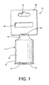
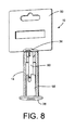
- a hang tag assembly 10 in accordance with the present disclosure is shown retaining a hole saw 14.
- the hang tag assembly 10 enables the hole saw 14 to be secured to a hang tag in a manner that is not easily removed and that maximizes exposure of the hole saw 14 while protectively covering the circular cutting edge.
- the hang tag assembly 10 does not require the use of a separate tool for installation on the hole saw 14. Once installed on the hole saw 14, the hang tag assembly 10 cannot be removed without the use of a separate tool or without breaking a component of the hang tag assembly 10.
- the hole saw 14 comprises a generally cylindrical body 16 that defines an axis A.
- the body 16 includes a first end portion 18 and a second end portion 20.
- the first end portion 18 comprises the mounting portion of the hole saw 14 and is configured to secure the hole saw body 16 to an arbor (not shown) of a driving tool (not shown), such as a power drill.
- the mounting portion 18 is configured to secure the cylindrical body 16 to the arbor of the driving tool with the axis A aligned with the axis of rotation of the arbor.
- the second end portion 20 of the cylindrical body 16 comprises the cutting portion of the hole saw 14 and includes a circular cutting edge portion 22 that is centered on the axis A.
- the circular cutting edge portion 22 resides substantially in a single plane S that is perpendicular to the axis A.
- the diameter of the cylindrical body 16 and circular cutting edge 22 defines the size of the hole saw 14.
- Hole saws, such as the hole saw 14 range generally in size from five-eighths of an inch to six inches in diameter although smaller and larger hole saw diameters are possible.
- the cutting edge portion 22 includes a plurality of cutting teeth (not visible). The number, size, and geometry of the teeth can be varied for cutting different materials. In embodiments, slots, or gullets, (not shown) may be formed between the cutting teeth to provide openings for the exit or removal of cutting debris. In other embodiments, the cutting edge 22 may be encrusted with a hard, gritty material, such as diamond or carbide, (not shown) for use in boring holes in materials, such as brick, concrete, glass, and stone.
- a hard, gritty material such as diamond or carbide
- the mounting portion 18 includes an interior wall 24 that defines a bore 26, also referred to as an arbor hole, configured to receive an arbor (not shown) of a driving tool.
- the mounting portion 18 includes an outer surface 28 that defines an opening 30 into the bore 26.
- the bore 26 defines a bore axis B.
- the bore 26 is located in the mounting portion 18 with the bore axis B aligned with the axis of rotation A of the cylindrical body 16.
- the cylindrical body 16 of the hole saw 14 defines a hollow interior space 32.
- the bore 26 extends through the mounting portion and opens into the hollow interior space 32.
- the bore 26 is configured to receive an arbor of a driving tool.
- the interior wall 24 of the bore 26 defines one or more grooves or recesses 34 arranged parallel to the bore axis B.
- the grooves 34 are configured to receive complementarily configured splines (not shown) provided on the arbor.
- the grooves and splines cooperate to prevent rotational movement of the hole saw with respect to the arbor.
- the interior wall 24 can be threaded for meshing engagement with complementary threads (not shown) provided on the arbor (not shown).
- the arbor for a hole saw is configured to carry a drill bit, or pilot bit, (not shown) for boring a centering hole for the hole saw 14. When the arbor is secured to the hole saw, the pilot bit extends from the arbor in alignment with the axis A through the hollow interior of the hole saw to position the tip of the pilot bit beyond the cutting edge portion 22 of the hole saw 14.
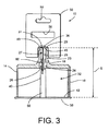
- a hole saw adapter 23 may be used to secure a hole saw 14 to the arbor of a driving tool.
- the adapter 23 comprises a generally cylindrical member having a first end portion adapted to be releasably secured to the mounting portion 28 of the hole saw 14.
- the second end portion of the adapter is configured to be releasably secured to the arbor of the driving tool.
- the adapter 23 includes an interior wall 25 that defines a bore 27 that extends through the adapter.
- the adapter includes an outer surface 29 that defines an opening 31 into the bore 27.
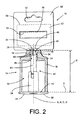
- a hang tag assembly 10 for a hole saw 14 has a two-piece construction including a cap member 36 and a base member 38.
- the cap member 36 and base member 38 are formed of a hard plastic material in an injection molding process.
- the cap member 36 is positioned adjacent the mounting portion of the hole saw, and the base member 38 is positioned adjacent the cutting edge portion of the hole saw.
- the cap member 36 and base member 38 are secured to each other by a linking structure 40 that extends through the bore 26 of the mounting portion 18 (and bore 27 of the adapter, if attached) and the hollow interior 32 of the of the hole saw 14 to the base member 38.
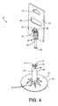
- the base member 38 of the hang tag assembly 10 includes an inner facing surface 42 and an outer facing surface 44.
- the inner facing surface 42 is arranged facing toward the cap member 36.
- the inner facing surface 42 is generally planar so it can sit flush against the circular cutting edge 22 of the hole saw 14 and is sized to enable the inner facing surface 42 to overlap the entire circular cutting edge 22.
- the base member 38 has a generally circular shape with a diameter that is slightly greater than the diameter of the circular cutting edge of the hole saw to be secured to the hang tag assembly.
- the base member 38 can have any shape or size that enables the inner facing surface 42 to substantially cover the cutting edge 22 of the hole saw.
- the cap member 36 of the hang tag assembly 10 includes an inner facing surface 46 that faces toward the base member 38 and an outer facing surface 48 faces away from the base member 38.
- the inner facing surface 42 of the cap member 36 is configured for positioning adjacent the outer surface 28 of the mounting portion 18 of the hole saw 14.
- the cap member 36 has a size and shape that enables the inner facing surface 42 to overlap substantially the entire opening 30 to the bore defined in the outer surface 28 of the mounting portion 18.
- the cap member 36 includes a display card portion 50.
- the display card portion 50 has a generally planar configuration that defines a hanging slot 52.
- the hanging slot 52 enables the hang tag assembly 10 (with the hole saw 14 secured thereto) to be supported by a hook (not shown) in a display rack.
- the display card portion 50 is formed integrally with the cap member 36.
- the display card portion 50 can be formed as a separate component that is affixed to the cap member 36.
- the hang tag assembly 10 is configured to support the hole saw 14 with the axis A of the hole saw arranged generally parallel to the display card portion 50 although in other embodiments the display card portion 50 can have other orientations with respect to the hole saw.
- the display card portion 50 can be incorporated into the base member 38 of the hang tag assembly 10 rather than the cap member 36.
- the hang tag assembly 10 enables a security device 54, such as a Sensormatic tag, to be incorporated into the package to deter theft from a retail store.
- the security device 54 is received in a recess 56 defined in a surface 57 of the display card portion 50.
- a label 59 is adhered to the surface 57 over the recess 56 to prevent the security device 54 from being easily removed and to conceal the security device 54 from view.
- the linking structure 40 extends between and connects the inner facing surface 42 of the base member 38 to the inner facing surface 46 of the cap member 36.
- the linking structure 40 includes a base linking structure 58 and a cap linking structure 60.
- the base linking structure 58 is provided as an integral component of the base member 38
- the cap linking structure 60 is provided as an integral component of the cap member 36.
- the cap linking structure 60 comprises a stem that extends generally perpendicularly from the inner facing surface 46 of the cap member 36.
- the stem 60 is sized to extend through the bore 26 defined in the mounting portion 18 of the hole saw 14 ( FIG. 2 ) as well as the bore 27 defined in the adapter 23 if the adapter 23 is attached to the hole saw 14 ( FIG. 3 ).
- the stem 60 extends through the bore and into the hollow interior 32 defined by the cylindrical body 16 of the hole saw 14.
- the base linking structure 58 of the base member 38 comprises a post or column that extends generally perpendicularly from the inner facing surface 42.
- the post 58 is located within the hollow interior 32 of the hole saw 14.
- the base member 38 includes ribs 62 that extend radially from the post 58 that connect the outer surface 64 of the post 58 to the inner facing surface 42 of the base member 38.
- the ribs 62 are oriented generally parallel to the post 58 and perpendicular to the inner facing surface 42 of the base member 38 and serve to strengthen the post 58 against bending relative to the base member 38.
- the stem 60 is configured to extend from the inner facing surface 46 of the cap member 36 a length or distance F
- the post 58 is configured to extend from the inner facing surface 42 of the base member 38 a length or distance G.
- the distances F, G are selected to enable the post 58 and the stem 60 to meet within the hollow interior 32 of the hole saw 14.
- the post 58 and the stem 60 of the linking structure 40 are provided with complementarily configured locking features that cooperate to secure the post and stem to each other within the hollow interior 32 of the hole saw 14.
- the locking features of the post 58 and stem 60 are configured to have a snap fit engagement with each other to secure the base member 38 and the cap member 36 together.
- the post 58 includes an interior wall 66 that defines a channel 68.
- the channel 68 defines a channel axis C that is arranged generally parallel to the axis A ( FIG. 2 ) of the hole saw.
- a distal end portion 70 of the post 58 defines an opening 72 into the channel 68.
- the distal end portion 70 of the post 58 includes flange structures 74 that extend from the interior wall 66 of the channel 68 toward the channel axis C.
- the flange structures 74 cause the width of the opening 72 to be smaller than the width or diameter of the channel 68.
- the flange structures 74 include locking surfaces 76 that are oriented toward the base member 38.
- the locking surfaces 76 are arranged substantially perpendicular to the axis C of the channel.
- the flange structures 74 also include chamfered or beveled surfaces 78 that are oriented away from the base member 38.
- the chamfered or beveled surfaces 78 at least partially surround and define the opening 72 into the channel 68.
- the stem 60 includes a ridge portion 80 having a width or diameter that is greater than the width or diameter of the portions of the stem 60 adjacent the ridge portion 80.
- the ridge portion 80 includes a chamfered or beveled surface 82 that faces generally away from the cap member 36.
- the ridge portion 80 also includes a locking surface 84 that faces toward the cap member 36 and is oriented substantially perpendicular to the axis D of the stem 60.
- the ridge portion 80 of the stem has an outer diameter that is slightly greater than the width or diameter of the opening 72 into the channel 68 defined by the flange structures 74.
- the outer diameter of the ridge portion 80 is less than the inner diameter of the remaining portions of the channel 68.
- slots 86 are defined in the post 58 that extend through the distal end portion 70 of the post and are connected to the opening 72. The slots 86 separate the flange structures 74 from each other and moves the fulcrum of the flange structures 74 away from the distal end portion 70 of the post and toward the base member 38.
- the narrower portion of the stem 60 permits the flange structures 74 to relax and return to their normal positions as depicted in FIG. 7 .
- the locking surfaces 76 of the flange structures 74 are positioned in front of and facing the locking surface 84 of the ridge structure 80 thereby preventing the withdrawal of the ridge portion 80 of the stem from the channel 68.
- the inner facing surface 42 of the base member 38 and the inner facing surface 46 of the cap member 36 are retained a predetermined distance E apart from each other.
- the distance E corresponds substantially to the height of the hole saw.
- the height of the hole saw corresponds to the distance between the outer surface 28 of the mounting portion 18 and the circular cutting edge 22 ( FIG. 2 ).
- the height of the hole saw 14 corresponds to the distance between the outer surface 29 of the adapter and the cutting edge portion 22 of the hole saw ( FIG. 3 ).
- the hang tag assembly 10 is also configured to prevent or limit rotational movement of the hole saw 14 with respect to the cap member 36 and base member 38.
- the stem 60 of the cap member 36 includes ribs or splines 88 that extend along the stem 60 generally parallel to the stem axis D.
- the splines 88 are configured complementary to the grooves 34 defined in the bore 26. When the stem 60 is advanced through the bore 26 in the mounting portion 18, the splines 88 are received the grooves 34.
- the splines 88 can be configured to provide a friction fit within a threaded bore in the mounting portion of a hole saw.
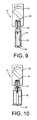
- FIGS. 8-10 show embodiments of hang tag assemblies 10 that are adapted to support and retain various sizes and types of hole saws 14.
- a single ridge portion 80 is provided on the stem which enables the hang tag assembly 10 to be used to secure hole saws of a particular height.
- a plurality of ridge portions can be provided on the stem at predetermined positions relative to the stem axis D to enable a particular hang tag assembly 10 to accommodate hole saws of varying heights.
- the base member 38 has been described as having the female portion (post) and the cap member 36 as having the male portion (stem) of the snap-fit joint, the male and female portions of the snap-fit joint can be swapped so that the base member 38 includes the male portion (stem) and the cap member 36 includes the female portion (post) of the snap-fit joint.
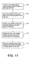
- FIG. 11 A flowchart depicting a method of packaging a hole saw is shown in FIG. 11 .
- the circular cutting edge of the hole saw is positioned against a planar surface, i.e., the inner facing surface, of a base member of a hang tag assembly (block 100).
- the base member includes a post that extends from the planar surface into the hollow interior defined by the hole saw.
- the hole saw is positioned on the planar surface with the post aligned with the bore defined in the mounting portion of the hole saw (block 104).
- a cap member of the hang tag assembly is then positioned adjacent the mounting portion of the hole saw (block 108).
- the cap member includes a stem. The stem of the cap member is advanced through the bore and into the hollow interior of the hole saw (block 110).
- the post extending from the base member includes an interior wall that defines a channel configured to receive the stem portion that extends from the cap member.
- the stem and the interior wall of the post are configured to have a snap-fit engagement with each other to secure the cap member to the base member.
- the cap member is pressed toward the base member until the stem snaps into place in the channel of the post (block 114).
- the post and stem serve to position the cap member a predetermined distance from the base member that corresponds to the height of the hole saw.
- the configuration of the hang tag assembly provides advantages over previously known packaging assemblies for hole saw. For example, the use of snap-fit type locking features enables the cap member to be locked to the base member without having to use a separate tool while making them difficult to separate the without using a separate tool or breaking one of the parts. When a hole saw is secured between the cap member and the base member as described above, the locking features of the linking structures are substantially enclosed within the hollow interior of the hole saw which further enhances security. In addition, the design of the hang tag assembly allows for nearly full exposure of the hole saw on store shelves and display racks while maintaining the cutting edge safely covered.
Landscapes
- Engineering & Computer Science (AREA)
- Mechanical Engineering (AREA)
- Packaging Of Annular Or Rod-Shaped Articles, Wearing Apparel, Cassettes, Or The Like (AREA)
- Details Of Rigid Or Semi-Rigid Containers (AREA)
- Packages (AREA)
Claims (14)
- Procédé d'emballage d'une scie cylindrique (14) comprenant les étapes consistant à :positionner une partie de bord de coupe circulaire (22) de la scie cylindrique (14) contre une surface (42) d'un élément de base (38) d'un ensemble étiquette volante (10), l'élément de base (38) comprenant un montant (58) qui s'étend de la surface (42) dans un intérieur creux (32) défini par la scie cylindrique (14) ;positionner un élément capuchon (36) de l'ensemble étiquette volante (10) à proximité d'une partie de montage (18) de la scie cylindrique (14), l'élément capuchon (36) comprenant une tige (60) et une partie carte de présentation (50) ;avancer la tige (60) de l'élément capuchon (36) à travers un alésage (26) défini dans la partie de montage (18) de la scie cylindrique (14) et dans l'intérieur creux (32) de la scie cylindrique (14) ; etfixer le montant (58) à la tige (60) au sein de l'intérieur creux (32) de la scie cylindrique (14), le montant (58) et la tige (60) étant pourvus de moyens de verrouillage configurés pour être complémentaires, qui coopèrent pour fixer le montant et la tige l'un à l'autre au sein de l'intérieur creux (12) de la scie cylindrique (14).
- Procédé selon la revendication 1, dans lequel :lorsque le montant (58) et la tige (60) sont fixés ensemble, la partie capuchon est positionnée à une distance prédéterminée de l'élément de base (38), la distance prédéterminée correspondant à une hauteur de la scie cylindrique (14).
- Procédé selon la revendication 1, dans lequel :le montant (58) comprend une paroi intérieure (66) qui définit un canal (68) et une partie d'extrémité distale (70) qui définit une ouverture (72) dans le canal (68) ; etla tige (60) est avancée à travers l'ouverture (72) et dans le canal (68) défini dans le montant (58).
- Procédé selon la revendication 3, dans lequel :la tige (60) est configurée pour une mise en prise par encliquetage avec le montant (58) dans le canal (68).
- Procédé selon la revendication 4, dans lequel :le montant (58) comprend des structures de rebord (74) qui font saillie dans le canal (68) depuis la paroi intérieure (66) ;la tige (60) comprend une partie arête (80) ;à mesure que la tige (60) est avancée dans le canal (68), la partie arête (80) de la tige (60) dévie les structures de rebord (74) vers l'extérieur pour qu'il soit possible de faire avancer la partie arête (80) au-delà des structures de rebord (74) dans le canal ; etaprès que la partie arête (80) a été avancée au-delà des parties de rebord (74) dans le canal (68), les structures de rebord (74) retournent à leurs positions normales pour empêcher que la partie arête (80) soit retirée du canal (68).
- Emballage de présentation d'une scie cylindrique (14), comprenant :une scie cylindrique (14) comprenant un corps cylindrique (16) ayant une partie de bord de coupe (22) et une partie de montage (18), le corps cylindrique (16) définissant un intérieur creux (32), la partie de montage (18) comprenant une surface extérieure (28) qui définit un alésage (26) destiné à recevoir un arbre d'outil d'entraînement ; etun ensemble étiquette volante (10) comprenant :un élément de base (38) ayant une surface (42) et une première structure de liaison (58) qui s'étend depuis la surface ;un élément capuchon (36) ayant une surface intérieure (46) et une seconde structure de liaison (60) qui s'étend depuis la surface intérieure (46) ; etune partie carte de présentation (50) liée audit élément capuchon (36) ;dans lequel :ladite partie de bord de coupe (22) de ladite scie cylindrique (14) est positionnée contre ladite surface (42) dudit élément de base (38) ;ladite surface intérieure (46) dudit élément capuchon (36) est positionnée à proximité de ladite surface extérieure (28) de ladite partie de montage (18) ;ladite seconde structure de liaison (60) s'étend à travers ledit alésage (26) défini dans ladite surface extérieure (28), et dans ledit intérieur creux (32) de ladite scie cylindrique (14) ;ladite première structure de liaison (58) est fixée à ladite seconde structure de liaison (60) au sein dudit intérieur creux (32) pour appliquer ledit élément capuchon (36) sur ledit élément de base (38), la première structure de liaison (58) comprenant un montant et la seconde structure de liaison (60) comprenant une tige, et le montant et la tige étant pourvus de moyens de verrouillage configurés pour être complémentaires, qui coopèrent pour fixer le montant et la tige l'un à l'autre au sein de l'intérieur creux (32) de la scie cylindrique (14).
- Ensemble selon la revendication 6, dans lequel :ladite première structure de liaison (58) et ladite seconde structure de liaison (60) maintiennent ladite surface (42) dudit élément de base (38) et ladite surface intérieure (46) dudit élément capuchon (36) à une distance prédéterminée l'une de l'autre, ladite distance prédéterminée correspondant à une distance entre ladite partie de bord de coupe (22) et ladite surface extérieure (28) de ladite partie de montage (18) de ladite scie cylindrique (14).
- Ensemble selon la revendication 6, dans lequel :ladite première structure de liaison (58) et ladite seconde structure de liaison (60) sont configurées pour une mise en prise par encliquetage de l'une avec l'autre afin de fixer ladite première structure de liaison (58) à ladite seconde structure de liaison (60).
- Ensemble selon la revendication 8, dans lequel :ladite première structure de liaison (58) comprend un montant (58) qui définit un canal (68) ;ladite seconde structure de liaison (60) comprend une tige (60) qui est reçue dans ledit canal (68).
- Ensemble selon la revendication 6, dans lequel :ledit ensemble étiquette volante (10) comprend un dispositif de sécurité (54), ouladite surface (42) dudit élément de base (38) recouvre ladite partie de bord de coupe (22) de ladite scie cylindrique (14).
- Ensemble étiquette volante (10) destiné à une scie cylindrique (14), comprenant :un élément de base (38) ayant une surface (42) et une première structure de liaison (58) qui s'étend depuis ladite surface (42) ;un élément capuchon (36) ayant une surface intérieure (46) et une seconde structure de liaison (60) qui s'étend depuis ladite surface intérieure (46) ; etune partie carte de présentation (50) liée audit élément capuchon (36), ladite partie carte de présentation (50) définissant une fente d'accrochage (52) ;dans lequel :ladite première structure de liaison (58) et ladite seconde structure de liaison (60) sont configurées pour être fixées l'une à l'autre afin d'appliquer ledit élément capuchon (36) sur ledit élément de base (38), la première structure de liaison (58) comprenant un montant et la seconde structure de liaison (60) comprenant une tige, et le montant et la tige étant pourvus de moyens de verrouillage configurés pour être complémentaires, qui coopèrent pour fixer le montant et la tige l'un à l'autre au sein de l'intérieur creux (32) de la scie cylindrique (14) ;ladite surface planaire (42) dudit élément est configurée pour être placée contre une partie de bord de coupe circulaire (22) de scie cylindrique (14) ;ladite surface intérieure (46) dudit élément capuchon (36) est configurée pour être positionnée à proximité d'une partie de montage (18) de la scie cylindrique (14) ;ladite seconde structure de liaison (60) est configurée pour s'étendre à travers un alésage (26) défini par la partie de montage (18), lorsque ladite surface intérieure (46) est positionnée à proximité de la partie de montage (18) de la scie cylindrique (14) ;lorsque ladite surface (42) dudit élément de base (38) est positionnée à proximité de la partie de bord de coupe (22) de la scie cylindrique (14) et que ladite surface intérieure (46) dudit élément capuchon (36) est positionnée à proximité de la partie de montage (18) de la scie cylindrique (14), ladite seconde structure de liaison (60) s'étendant à travers l'alésage (26), ladite première structure de liaison (58) et ladite seconde structure de liaison (60) sont configurées pour se rencontrer au sein d'un intérieur creux (32) défini dans la scie cylindrique (14).
- Ensemble étiquette volante (10) selon la revendication 11, dans lequel :ladite première structure de liaison (58) et ladite seconde structure de liaison (60) sont configurées pour être fixées l'une à l'autre au sein de l'intérieur creux (32) de la scie cylindrique (14), ouladite surface (42) dudit élément de base (38) a une forme circulaire qui est configurée pour recouvrir la partie de bord de coupe circulaire (22) de la scie cylindrique (14).
- Ensemble étiquette volante (10) selon la revendication 11, comprenant en outre :un dispositif de sécurité (54) lié à ladite partie carte de présentation (50).
- Ensemble étiquette volante (10) selon la revendication 11, dans lequel :lorsque ladite première structure de liaison (58) etladite seconde structure de liaison (60) sont fixées ensemble, ladite surface intérieure (46) dudit élément capuchon (36) est maintenue à une distance prédéterminée de ladite surface (42) dudit élément de base (38), ladite distance prédéterminée correspondant à une hauteur de la scie cylindrique (14).
Applications Claiming Priority (2)
| Application Number | Priority Date | Filing Date | Title |
|---|---|---|---|
| US13/336,836 US8443972B1 (en) | 2011-12-23 | 2011-12-23 | Hang tag assembly for a hole saw |
| PCT/US2012/071539 WO2013096937A1 (fr) | 2011-12-23 | 2012-12-22 | Ensemble étiquette volante pour une scie cylindrique |
Publications (2)
| Publication Number | Publication Date |
|---|---|
| EP2794420A1 EP2794420A1 (fr) | 2014-10-29 |
| EP2794420B1 true EP2794420B1 (fr) | 2015-12-09 |
Family
ID=47595020
Family Applications (1)
| Application Number | Title | Priority Date | Filing Date |
|---|---|---|---|
| EP12816592.5A Active EP2794420B1 (fr) | 2011-12-23 | 2012-12-22 | Ensemble etiquette volante pour une scie cylindrique |
Country Status (7)
| Country | Link |
|---|---|
| US (2) | US8443972B1 (fr) |
| EP (1) | EP2794420B1 (fr) |
| JP (1) | JP6096215B2 (fr) |
| CN (1) | CN104203770B (fr) |
| BR (1) | BR112014015432A2 (fr) |
| IN (1) | IN2014CN04923A (fr) |
| WO (1) | WO2013096937A1 (fr) |
Families Citing this family (14)
| Publication number | Priority date | Publication date | Assignee | Title |
|---|---|---|---|---|
| US8646601B2 (en) * | 2012-04-23 | 2014-02-11 | Irwin Industrial Tool Company | Hole saw kit |
| CA2951556A1 (fr) * | 2014-06-10 | 2015-12-17 | Winston Products Llc | Dispositif de nettoyage |
| TWI477370B (zh) * | 2014-08-15 | 2015-03-21 | Chih-Chien Hsieh | 手工具吊架固定結構 |
| US10329067B2 (en) * | 2015-08-21 | 2019-06-25 | Multi Packaging Solutions, Inc. | Security packaging |
| GB2544737B (en) | 2015-11-23 | 2018-11-07 | Peri Dent Ltd | System and method for fastening a container and a closure |
| DE102015225930A1 (de) * | 2015-12-18 | 2017-06-22 | Robert Bosch Gmbh | Verpackungseinheit |
| US10179420B2 (en) | 2017-04-27 | 2019-01-15 | Pearl Technologies Inc. | Safety cover for lightning punch |
| CN110374993A (zh) * | 2018-04-13 | 2019-10-25 | 银鼎精密元件(上海)有限公司 | 线性滑轨之滑块结构 |
| US10894645B2 (en) * | 2019-03-01 | 2021-01-19 | Robert Bosch Tool Corporation | Elongated tool hang tag package with bridge strap |
| US10815040B2 (en) * | 2019-03-19 | 2020-10-27 | Huang-Tung Hsu | Antitheft display pack for hand tool |
| EP3947185A4 (fr) | 2019-06-17 | 2023-06-14 | Milwaukee Electric Tool Corporation | Emballage de trépan |
| US11577422B2 (en) * | 2020-01-31 | 2023-02-14 | Husqvarna Ab | Display or storage assembly for handheld power tool |
| US11872642B2 (en) | 2021-11-12 | 2024-01-16 | Robert James Suhling | Dynamicaly configurable arbor assembly apparatus |
| TWI812270B (zh) * | 2022-06-10 | 2023-08-11 | 陸同五金機械有限公司 | 起子頭吊卡 |
Family Cites Families (45)
| Publication number | Priority date | Publication date | Assignee | Title |
|---|---|---|---|---|
| US3053424A (en) | 1960-08-04 | 1962-09-11 | Cheyenne A Reinhard | Carrier for circular saw blades |
| US3259231A (en) * | 1964-08-17 | 1966-07-05 | Black & Decker Mfg Co | Package for article of manufacture |
| US4019632A (en) | 1976-05-11 | 1977-04-26 | The Wright Tool & Forge Co. | Tool handle display and hanger device |
| US4199060A (en) * | 1978-07-20 | 1980-04-22 | Howard Hardware Products, Inc. | Lock installation kit |
| US4415080A (en) | 1982-01-22 | 1983-11-15 | Champion International Corporation | Slitter blade carrying case |
| US4702373A (en) | 1986-02-24 | 1987-10-27 | Meade Dan G | Hub cover interacting with reel of magnetic tape for forming document storage compartment |
| US4784263A (en) | 1987-07-09 | 1988-11-15 | Stanley Jeffrey A | Saw blade carrier |
| JPH0671488U (ja) * | 1993-03-12 | 1994-10-07 | 株式会社ケイ・アイ・ドリル | 切削工具の収納容器 |
| JP3052037B2 (ja) * | 1993-07-22 | 2000-06-12 | 本田技研工業株式会社 | スプライン結合構造 |
| GB2316928B (en) * | 1996-09-06 | 2001-01-24 | Black & Decker Inc | Packaging for a centrally apertured disc |
| EP0841259B1 (fr) | 1996-10-16 | 2000-01-05 | rose plastic GmbH | Elément de suspension pour outils à manche SDS |
| US5740911A (en) | 1997-04-10 | 1998-04-21 | Chou; Ta-Ching | Display pack having a security device |
| CA2280458C (fr) | 1998-08-14 | 2006-07-25 | Maxtech Manufacturing Inc. | Dispositif de retenue avec mecanisme de securite de manchon pour tournevis ou outils du meme genre |
| US5988381A (en) | 1998-12-28 | 1999-11-23 | Hand Tool Design Corporation | Tool display pack with a security device |
| US6032797A (en) | 1999-02-26 | 2000-03-07 | Kao; Jui-Chien | Socket stud for tool suspension rack |
| DE29903874U1 (de) | 1999-03-04 | 2000-01-13 | Rose Plastic Gmbh | Halterung zur Aufhängung von Werkzeugen |
| US6161693A (en) | 1999-05-03 | 2000-12-19 | Black & Decker Inc. | Reusable display package for circular blade or other display item |
| US6092656A (en) | 1999-05-28 | 2000-07-25 | Ernst; Gregory R. | Wrench socket holder with locking member |
| SE515647C2 (sv) | 2000-01-11 | 2001-09-17 | Kapman Ab | Eggskydd för hålsåg |
| US20030029748A1 (en) | 2001-08-07 | 2003-02-13 | American Tool Companies, Inc. | Saw blade package and carry case |
| EP1417136B1 (fr) | 2001-08-10 | 2008-06-25 | Maxtech Manufacturing Inc. | Support de produit a securite de point de vente |
| US6986538B1 (en) | 2002-01-04 | 2006-01-17 | Ecker Robert J | Device for storing and carrying hole saws |
| TW510289U (en) | 2002-01-22 | 2002-11-11 | Test Rite Int Co Ltd | Hanging card for hitching socket |
| US6672555B2 (en) | 2002-01-23 | 2004-01-06 | Chi Tsai Chang | Structure of a suspension device for displaying articles |
| US6868966B2 (en) * | 2002-07-30 | 2005-03-22 | Black & Decker Inc. | Self-standing saw blade package |
| US6883664B2 (en) | 2002-08-20 | 2005-04-26 | Daniel Lee | Tool display member |
| US6581894B1 (en) | 2002-09-30 | 2003-06-24 | Hui Lin Tong | Display device for article for sale |
| US6729468B1 (en) | 2003-03-28 | 2004-05-04 | Thomas N Dobmeier | Circular saw blade holder |
| JP2004323081A (ja) * | 2003-04-25 | 2004-11-18 | Yunika Kk | 包装容器及び包装容器用保持アダプター |
| US7210663B2 (en) | 2003-06-17 | 2007-05-01 | Jpj Investment Holding Corporation | Tool securing mechanism for hangtag assembly |
| US6935516B2 (en) | 2003-09-23 | 2005-08-30 | Kuo Chuan Chiang | Tool holding and displaying device |
| JP2005102901A (ja) * | 2003-09-30 | 2005-04-21 | Kyoto Tool Co Ltd | 工具ホルダー |
| US7066327B2 (en) * | 2003-12-17 | 2006-06-27 | Black & Decker Inc. | Saw blade packaging |
| DE102005003416B4 (de) | 2004-04-01 | 2013-09-12 | Peter Rösler | Aufhänger für Bohrer |
| US7424951B2 (en) | 2004-11-01 | 2008-09-16 | Bobby Hu | Hanger for wrench |
| US7287644B2 (en) | 2005-05-18 | 2007-10-30 | Kun-Chen Chen | Suspension device for a tool socket |
| US20060284001A1 (en) | 2005-06-16 | 2006-12-21 | Design For Living, L.L.C. | Roll holder and dispenser for paper products |
| US7264213B2 (en) | 2005-08-11 | 2007-09-04 | Yung Yuan Liu | Hanging device for tool |
| GB0521697D0 (en) | 2005-10-25 | 2005-11-30 | Rae Scott W | Holesaw + arbour holder |
| US7527149B2 (en) | 2006-01-18 | 2009-05-05 | Proxene Tools Co., Ltd. | Exhibition device for reversal spanners |
| US20070193313A1 (en) * | 2006-02-21 | 2007-08-23 | Yu-Chi Tsai | Anti-theft tag |
| US7824137B2 (en) * | 2006-05-17 | 2010-11-02 | Maxtech Consumer Products Limited | Universal quick connect system for a hole saw |
| US7565973B2 (en) | 2007-05-03 | 2009-07-28 | Chi-Tsai Chang | Suspension tag for socket wrench |
| DE102008043431A1 (de) * | 2008-11-04 | 2010-05-06 | Hilti Aktiengesellschaft | Aufhängevorrichtung für ein Schneidwerkzeug |
| DE202011000751U1 (de) * | 2011-03-31 | 2011-05-26 | wolfcraft GmbH, 56746 | Gehäuse, insbesondere Verpackungsgehäuse für ein Werkzeug |
-
2011
- 2011-12-23 US US13/336,836 patent/US8443972B1/en active Active
-
2012
- 2012-12-22 EP EP12816592.5A patent/EP2794420B1/fr active Active
- 2012-12-22 BR BR112014015432A patent/BR112014015432A2/pt not_active Application Discontinuation
- 2012-12-22 JP JP2014548997A patent/JP6096215B2/ja not_active Expired - Fee Related
- 2012-12-22 IN IN4923CHN2014 patent/IN2014CN04923A/en unknown
- 2012-12-22 CN CN201280068241.9A patent/CN104203770B/zh active Active
- 2012-12-22 WO PCT/US2012/071539 patent/WO2013096937A1/fr active Application Filing
-
2013
- 2013-05-20 US US13/898,226 patent/US8919552B2/en active Active
Also Published As
| Publication number | Publication date |
|---|---|
| BR112014015432A2 (pt) | 2017-07-04 |
| CN104203770A (zh) | 2014-12-10 |
| WO2013096937A1 (fr) | 2013-06-27 |
| US20140042047A1 (en) | 2014-02-13 |
| CN104203770B (zh) | 2016-10-12 |
| US8443972B1 (en) | 2013-05-21 |
| JP6096215B2 (ja) | 2017-03-15 |
| EP2794420A1 (fr) | 2014-10-29 |
| US8919552B2 (en) | 2014-12-30 |
| JP2015511200A (ja) | 2015-04-16 |
| IN2014CN04923A (fr) | 2015-09-18 |
Similar Documents
| Publication | Publication Date | Title |
|---|---|---|
| EP2794420B1 (fr) | Ensemble etiquette volante pour une scie cylindrique | |
| US4514882A (en) | Device for retaining in side-by-side relationship flexible tying means such as shoelaces | |
| EP2861386B1 (fr) | Dispositif de maintien ayant une partie de tige comprenant un ergot d'immobilisation | |
| US5641079A (en) | Tool holder | |
| US20060201836A1 (en) | Specialty product hang tag | |
| US7836604B2 (en) | Picture hanger assembly and method | |
| US8794453B2 (en) | Security hook for product display | |
| US8127946B2 (en) | Eyewear display system | |
| US8757377B2 (en) | Security hanger tag for saw blade | |
| US10486876B2 (en) | Hang Tag | |
| CA2813217A1 (fr) | Systeme d'affichage pour article de lunetterie | |
| EP3263479B1 (fr) | Étiquette volante | |
| WO2012112115A1 (fr) | Adaptateur | |
| US20150114862A1 (en) | Safety device for tool display tag | |
| US20120234709A1 (en) | Drill bit suspension structure | |
| US9078532B1 (en) | Circular lock assembly | |
| US8567220B1 (en) | Magnetic lock assembly | |
| US20100176015A1 (en) | Hanger for cutting tool | |
| JP5225633B2 (ja) | ビットハンガー | |
| EP3087012B1 (fr) | Emballage à étiquette volante pour une lame de scie | |
| CA2813427C (fr) | Systeme d'affichage pour article de lunetterie | |
| US11707811B2 (en) | Tool storage pod system | |
| JP4648926B2 (ja) | 簡易式回転可能式の盗難防止工具フレーム | |
| US20190057590A1 (en) | Anti-Theft Hangtag | |
| US6397649B1 (en) | Keyhole barrier system and method |
Legal Events
| Date | Code | Title | Description |
|---|---|---|---|
| PUAI | Public reference made under article 153(3) epc to a published international application that has entered the european phase |
Free format text: ORIGINAL CODE: 0009012 |
|
| 17P | Request for examination filed |
Effective date: 20140723 |
|
| AK | Designated contracting states |
Kind code of ref document: A1 Designated state(s): AL AT BE BG CH CY CZ DE DK EE ES FI FR GB GR HR HU IE IS IT LI LT LU LV MC MK MT NL NO PL PT RO RS SE SI SK SM TR |
|
| DAX | Request for extension of the european patent (deleted) | ||
| 17Q | First examination report despatched |
Effective date: 20150331 |
|
| GRAP | Despatch of communication of intention to grant a patent |
Free format text: ORIGINAL CODE: EPIDOSNIGR1 |
|
| INTG | Intention to grant announced |
Effective date: 20150715 |
|
| GRAS | Grant fee paid |
Free format text: ORIGINAL CODE: EPIDOSNIGR3 |
|
| GRAA | (expected) grant |
Free format text: ORIGINAL CODE: 0009210 |
|
| AK | Designated contracting states |
Kind code of ref document: B1 Designated state(s): AL AT BE BG CH CY CZ DE DK EE ES FI FR GB GR HR HU IE IS IT LI LT LU LV MC MK MT NL NO PL PT RO RS SE SI SK SM TR |
|
| REG | Reference to a national code |
Ref country code: GB Ref legal event code: FG4D |
|
| REG | Reference to a national code |
Ref country code: AT Ref legal event code: REF Ref document number: 764473 Country of ref document: AT Kind code of ref document: T Effective date: 20151215 Ref country code: CH Ref legal event code: EP |
|
| REG | Reference to a national code |
Ref country code: IE Ref legal event code: FG4D |
|
| REG | Reference to a national code |
Ref country code: DE Ref legal event code: R096 Ref document number: 602012013011 Country of ref document: DE |
|
| REG | Reference to a national code |
Ref country code: LT Ref legal event code: MG4D |
|
| REG | Reference to a national code |
Ref country code: NL Ref legal event code: MP Effective date: 20151209 |
|
| PG25 | Lapsed in a contracting state [announced via postgrant information from national office to epo] |
Ref country code: ES Free format text: LAPSE BECAUSE OF FAILURE TO SUBMIT A TRANSLATION OF THE DESCRIPTION OR TO PAY THE FEE WITHIN THE PRESCRIBED TIME-LIMIT Effective date: 20151209 Ref country code: NO Free format text: LAPSE BECAUSE OF FAILURE TO SUBMIT A TRANSLATION OF THE DESCRIPTION OR TO PAY THE FEE WITHIN THE PRESCRIBED TIME-LIMIT Effective date: 20160309 Ref country code: LT Free format text: LAPSE BECAUSE OF FAILURE TO SUBMIT A TRANSLATION OF THE DESCRIPTION OR TO PAY THE FEE WITHIN THE PRESCRIBED TIME-LIMIT Effective date: 20151209 |
|
| REG | Reference to a national code |
Ref country code: AT Ref legal event code: MK05 Ref document number: 764473 Country of ref document: AT Kind code of ref document: T Effective date: 20151209 |
|
| PG25 | Lapsed in a contracting state [announced via postgrant information from national office to epo] |
Ref country code: BE Free format text: LAPSE BECAUSE OF NON-PAYMENT OF DUE FEES Effective date: 20151231 Ref country code: FI Free format text: LAPSE BECAUSE OF FAILURE TO SUBMIT A TRANSLATION OF THE DESCRIPTION OR TO PAY THE FEE WITHIN THE PRESCRIBED TIME-LIMIT Effective date: 20151209 Ref country code: GR Free format text: LAPSE BECAUSE OF FAILURE TO SUBMIT A TRANSLATION OF THE DESCRIPTION OR TO PAY THE FEE WITHIN THE PRESCRIBED TIME-LIMIT Effective date: 20160310 Ref country code: SE Free format text: LAPSE BECAUSE OF FAILURE TO SUBMIT A TRANSLATION OF THE DESCRIPTION OR TO PAY THE FEE WITHIN THE PRESCRIBED TIME-LIMIT Effective date: 20151209 Ref country code: RS Free format text: LAPSE BECAUSE OF FAILURE TO SUBMIT A TRANSLATION OF THE DESCRIPTION OR TO PAY THE FEE WITHIN THE PRESCRIBED TIME-LIMIT Effective date: 20151209 Ref country code: LV Free format text: LAPSE BECAUSE OF FAILURE TO SUBMIT A TRANSLATION OF THE DESCRIPTION OR TO PAY THE FEE WITHIN THE PRESCRIBED TIME-LIMIT Effective date: 20151209 Ref country code: NL Free format text: LAPSE BECAUSE OF FAILURE TO SUBMIT A TRANSLATION OF THE DESCRIPTION OR TO PAY THE FEE WITHIN THE PRESCRIBED TIME-LIMIT Effective date: 20151209 |
|
| PG25 | Lapsed in a contracting state [announced via postgrant information from national office to epo] |
Ref country code: IS Free format text: LAPSE BECAUSE OF FAILURE TO SUBMIT A TRANSLATION OF THE DESCRIPTION OR TO PAY THE FEE WITHIN THE PRESCRIBED TIME-LIMIT Effective date: 20151209 |
|
| PG25 | Lapsed in a contracting state [announced via postgrant information from national office to epo] |
Ref country code: IT Free format text: LAPSE BECAUSE OF FAILURE TO SUBMIT A TRANSLATION OF THE DESCRIPTION OR TO PAY THE FEE WITHIN THE PRESCRIBED TIME-LIMIT Effective date: 20151209 Ref country code: CZ Free format text: LAPSE BECAUSE OF FAILURE TO SUBMIT A TRANSLATION OF THE DESCRIPTION OR TO PAY THE FEE WITHIN THE PRESCRIBED TIME-LIMIT Effective date: 20151209 |
|
| REG | Reference to a national code |
Ref country code: CH Ref legal event code: PL |
|
| PG25 | Lapsed in a contracting state [announced via postgrant information from national office to epo] |
Ref country code: SK Free format text: LAPSE BECAUSE OF FAILURE TO SUBMIT A TRANSLATION OF THE DESCRIPTION OR TO PAY THE FEE WITHIN THE PRESCRIBED TIME-LIMIT Effective date: 20151209 Ref country code: SM Free format text: LAPSE BECAUSE OF FAILURE TO SUBMIT A TRANSLATION OF THE DESCRIPTION OR TO PAY THE FEE WITHIN THE PRESCRIBED TIME-LIMIT Effective date: 20151209 Ref country code: PT Free format text: LAPSE BECAUSE OF FAILURE TO SUBMIT A TRANSLATION OF THE DESCRIPTION OR TO PAY THE FEE WITHIN THE PRESCRIBED TIME-LIMIT Effective date: 20160411 Ref country code: AT Free format text: LAPSE BECAUSE OF FAILURE TO SUBMIT A TRANSLATION OF THE DESCRIPTION OR TO PAY THE FEE WITHIN THE PRESCRIBED TIME-LIMIT Effective date: 20151209 Ref country code: IS Free format text: LAPSE BECAUSE OF FAILURE TO SUBMIT A TRANSLATION OF THE DESCRIPTION OR TO PAY THE FEE WITHIN THE PRESCRIBED TIME-LIMIT Effective date: 20160409 Ref country code: EE Free format text: LAPSE BECAUSE OF FAILURE TO SUBMIT A TRANSLATION OF THE DESCRIPTION OR TO PAY THE FEE WITHIN THE PRESCRIBED TIME-LIMIT Effective date: 20151209 Ref country code: RO Free format text: LAPSE BECAUSE OF FAILURE TO SUBMIT A TRANSLATION OF THE DESCRIPTION OR TO PAY THE FEE WITHIN THE PRESCRIBED TIME-LIMIT Effective date: 20151209 |
|
| REG | Reference to a national code |
Ref country code: DE Ref legal event code: R097 Ref document number: 602012013011 Country of ref document: DE |
|
| REG | Reference to a national code |
Ref country code: IE Ref legal event code: MM4A |
|
| PG25 | Lapsed in a contracting state [announced via postgrant information from national office to epo] |
Ref country code: MC Free format text: LAPSE BECAUSE OF FAILURE TO SUBMIT A TRANSLATION OF THE DESCRIPTION OR TO PAY THE FEE WITHIN THE PRESCRIBED TIME-LIMIT Effective date: 20151209 |
|
| PLBE | No opposition filed within time limit |
Free format text: ORIGINAL CODE: 0009261 |
|
| STAA | Information on the status of an ep patent application or granted ep patent |
Free format text: STATUS: NO OPPOSITION FILED WITHIN TIME LIMIT |
|
| PG25 | Lapsed in a contracting state [announced via postgrant information from national office to epo] |
Ref country code: CH Free format text: LAPSE BECAUSE OF NON-PAYMENT OF DUE FEES Effective date: 20151231 Ref country code: IE Free format text: LAPSE BECAUSE OF NON-PAYMENT OF DUE FEES Effective date: 20151222 Ref country code: PL Free format text: LAPSE BECAUSE OF FAILURE TO SUBMIT A TRANSLATION OF THE DESCRIPTION OR TO PAY THE FEE WITHIN THE PRESCRIBED TIME-LIMIT Effective date: 20151209 Ref country code: DK Free format text: LAPSE BECAUSE OF FAILURE TO SUBMIT A TRANSLATION OF THE DESCRIPTION OR TO PAY THE FEE WITHIN THE PRESCRIBED TIME-LIMIT Effective date: 20151209 Ref country code: LI Free format text: LAPSE BECAUSE OF NON-PAYMENT OF DUE FEES Effective date: 20151231 |
|
| 26N | No opposition filed |
Effective date: 20160912 |
|
| PG25 | Lapsed in a contracting state [announced via postgrant information from national office to epo] |
Ref country code: SI Free format text: LAPSE BECAUSE OF FAILURE TO SUBMIT A TRANSLATION OF THE DESCRIPTION OR TO PAY THE FEE WITHIN THE PRESCRIBED TIME-LIMIT Effective date: 20151209 |
|
| PG25 | Lapsed in a contracting state [announced via postgrant information from national office to epo] |
Ref country code: BE Free format text: LAPSE BECAUSE OF FAILURE TO SUBMIT A TRANSLATION OF THE DESCRIPTION OR TO PAY THE FEE WITHIN THE PRESCRIBED TIME-LIMIT Effective date: 20151209 |
|
| REG | Reference to a national code |
Ref country code: FR Ref legal event code: ST Effective date: 20161125 |
|
| PG25 | Lapsed in a contracting state [announced via postgrant information from national office to epo] |
Ref country code: FR Free format text: LAPSE BECAUSE OF NON-PAYMENT OF DUE FEES Effective date: 20160209 |
|
| PG25 | Lapsed in a contracting state [announced via postgrant information from national office to epo] |
Ref country code: BG Free format text: LAPSE BECAUSE OF FAILURE TO SUBMIT A TRANSLATION OF THE DESCRIPTION OR TO PAY THE FEE WITHIN THE PRESCRIBED TIME-LIMIT Effective date: 20151209 |
|
| PG25 | Lapsed in a contracting state [announced via postgrant information from national office to epo] |
Ref country code: CY Free format text: LAPSE BECAUSE OF FAILURE TO SUBMIT A TRANSLATION OF THE DESCRIPTION OR TO PAY THE FEE WITHIN THE PRESCRIBED TIME-LIMIT Effective date: 20151209 Ref country code: HU Free format text: LAPSE BECAUSE OF FAILURE TO SUBMIT A TRANSLATION OF THE DESCRIPTION OR TO PAY THE FEE WITHIN THE PRESCRIBED TIME-LIMIT; INVALID AB INITIO Effective date: 20121222 |
|
| PG25 | Lapsed in a contracting state [announced via postgrant information from national office to epo] |
Ref country code: HR Free format text: LAPSE BECAUSE OF FAILURE TO SUBMIT A TRANSLATION OF THE DESCRIPTION OR TO PAY THE FEE WITHIN THE PRESCRIBED TIME-LIMIT Effective date: 20151209 |
|
| GBPC | Gb: european patent ceased through non-payment of renewal fee |
Effective date: 20161222 |
|
| PG25 | Lapsed in a contracting state [announced via postgrant information from national office to epo] |
Ref country code: MT Free format text: LAPSE BECAUSE OF FAILURE TO SUBMIT A TRANSLATION OF THE DESCRIPTION OR TO PAY THE FEE WITHIN THE PRESCRIBED TIME-LIMIT Effective date: 20151209 |
|
| PG25 | Lapsed in a contracting state [announced via postgrant information from national office to epo] |
Ref country code: LU Free format text: LAPSE BECAUSE OF NON-PAYMENT OF DUE FEES Effective date: 20151222 Ref country code: GB Free format text: LAPSE BECAUSE OF NON-PAYMENT OF DUE FEES Effective date: 20161222 |
|
| PG25 | Lapsed in a contracting state [announced via postgrant information from national office to epo] |
Ref country code: MK Free format text: LAPSE BECAUSE OF FAILURE TO SUBMIT A TRANSLATION OF THE DESCRIPTION OR TO PAY THE FEE WITHIN THE PRESCRIBED TIME-LIMIT Effective date: 20151209 |
|
| PG25 | Lapsed in a contracting state [announced via postgrant information from national office to epo] |
Ref country code: AL Free format text: LAPSE BECAUSE OF FAILURE TO SUBMIT A TRANSLATION OF THE DESCRIPTION OR TO PAY THE FEE WITHIN THE PRESCRIBED TIME-LIMIT Effective date: 20151209 Ref country code: TR Free format text: LAPSE BECAUSE OF FAILURE TO SUBMIT A TRANSLATION OF THE DESCRIPTION OR TO PAY THE FEE WITHIN THE PRESCRIBED TIME-LIMIT Effective date: 20151209 |
|
| PGFP | Annual fee paid to national office [announced via postgrant information from national office to epo] |
Ref country code: DE Payment date: 20230223 Year of fee payment: 11 |