EP2792414A1 - Sanitärbrause mit einem Brausekopf - Google Patents
Sanitärbrause mit einem Brausekopf Download PDFInfo
- Publication number
- EP2792414A1 EP2792414A1 EP20140000986 EP14000986A EP2792414A1 EP 2792414 A1 EP2792414 A1 EP 2792414A1 EP 20140000986 EP20140000986 EP 20140000986 EP 14000986 A EP14000986 A EP 14000986A EP 2792414 A1 EP2792414 A1 EP 2792414A1
- Authority
- EP
- European Patent Office
- Prior art keywords
- contour
- control slide
- control
- open position
- locking
- Prior art date
- Legal status (The legal status is an assumption and is not a legal conclusion. Google has not performed a legal analysis and makes no representation as to the accuracy of the status listed.)
- Granted
Links
- 239000000523 sample Substances 0.000 claims abstract description 42
- 230000013011 mating Effects 0.000 claims abstract description 10
- 230000005489 elastic deformation Effects 0.000 claims abstract description 3
- 230000007246 mechanism Effects 0.000 description 12
- 230000033001 locomotion Effects 0.000 description 7
- 239000007921 spray Substances 0.000 description 4
- 230000003213 activating effect Effects 0.000 description 2
- 230000000994 depressogenic effect Effects 0.000 description 2
- 238000011161 development Methods 0.000 description 2
- 230000018109 developmental process Effects 0.000 description 2
- 238000002955 isolation Methods 0.000 description 2
- 230000005540 biological transmission Effects 0.000 description 1
- 238000010276 construction Methods 0.000 description 1
- 230000008878 coupling Effects 0.000 description 1
- 238000010168 coupling process Methods 0.000 description 1
- 238000005859 coupling reaction Methods 0.000 description 1
- 230000009977 dual effect Effects 0.000 description 1
- 230000001747 exhibiting effect Effects 0.000 description 1
- 239000000463 material Substances 0.000 description 1
- 238000000034 method Methods 0.000 description 1
- 230000008569 process Effects 0.000 description 1
- 230000009467 reduction Effects 0.000 description 1
- XLYOFNOQVPJJNP-UHFFFAOYSA-N water Substances O XLYOFNOQVPJJNP-UHFFFAOYSA-N 0.000 description 1
Images



Classifications
-
- B—PERFORMING OPERATIONS; TRANSPORTING
- B05—SPRAYING OR ATOMISING IN GENERAL; APPLYING FLUENT MATERIALS TO SURFACES, IN GENERAL
- B05B—SPRAYING APPARATUS; ATOMISING APPARATUS; NOZZLES
- B05B1/00—Nozzles, spray heads or other outlets, with or without auxiliary devices such as valves, heating means
- B05B1/14—Nozzles, spray heads or other outlets, with or without auxiliary devices such as valves, heating means with multiple outlet openings; with strainers in or outside the outlet opening
- B05B1/16—Nozzles, spray heads or other outlets, with or without auxiliary devices such as valves, heating means with multiple outlet openings; with strainers in or outside the outlet opening having selectively- effective outlets
- B05B1/1609—Nozzles, spray heads or other outlets, with or without auxiliary devices such as valves, heating means with multiple outlet openings; with strainers in or outside the outlet opening having selectively- effective outlets with a selecting mechanism comprising a lift valve
-
- B—PERFORMING OPERATIONS; TRANSPORTING
- B05—SPRAYING OR ATOMISING IN GENERAL; APPLYING FLUENT MATERIALS TO SURFACES, IN GENERAL
- B05B—SPRAYING APPARATUS; ATOMISING APPARATUS; NOZZLES
- B05B1/00—Nozzles, spray heads or other outlets, with or without auxiliary devices such as valves, heating means
- B05B1/14—Nozzles, spray heads or other outlets, with or without auxiliary devices such as valves, heating means with multiple outlet openings; with strainers in or outside the outlet opening
- B05B1/16—Nozzles, spray heads or other outlets, with or without auxiliary devices such as valves, heating means with multiple outlet openings; with strainers in or outside the outlet opening having selectively- effective outlets
- B05B1/169—Nozzles, spray heads or other outlets, with or without auxiliary devices such as valves, heating means with multiple outlet openings; with strainers in or outside the outlet opening having selectively- effective outlets having three or more selectively effective outlets
-
- B—PERFORMING OPERATIONS; TRANSPORTING
- B05—SPRAYING OR ATOMISING IN GENERAL; APPLYING FLUENT MATERIALS TO SURFACES, IN GENERAL
- B05B—SPRAYING APPARATUS; ATOMISING APPARATUS; NOZZLES
- B05B1/00—Nozzles, spray heads or other outlets, with or without auxiliary devices such as valves, heating means
- B05B1/14—Nozzles, spray heads or other outlets, with or without auxiliary devices such as valves, heating means with multiple outlet openings; with strainers in or outside the outlet opening
- B05B1/18—Roses; Shower heads
-
- E—FIXED CONSTRUCTIONS
- E03—WATER SUPPLY; SEWERAGE
- E03C—DOMESTIC PLUMBING INSTALLATIONS FOR FRESH WATER OR WASTE WATER; SINKS
- E03C1/00—Domestic plumbing installations for fresh water or waste water; Sinks
- E03C1/02—Plumbing installations for fresh water
- E03C1/04—Water-basin installations specially adapted to wash-basins or baths
- E03C1/0408—Water installations especially for showers
- E03C1/0409—Shower handles
Definitions
- the invention relates to a sanitary shower with a shower head according to the preamble of claim 1.
- the shower head can have a keypad, with the showering process in any way different shower spray types are applicable to each other and / or separately.
- the shower head has at least two keypads exhibiting keypad.
- the feeler elements are, with the interposition of a feeler mechanism in operative connection with valves in the shower head. With manual pressure actuation of these feeler elements the shower spray type is adjustable.
- Each of the sensing elements is spring-biased to a closed position in which a flow path in the showerhead is closed.
- the respective probe element is pressed over a first stroke in an open position in which the flow path is open and in which a molded on the pressed probe element latching contour is in releasable latching engagement with a mating contour of an adjustable control slide.
- the control slide can be adjusted to release this locking engagement in an unlocking position in which the Tastelement-locking contour and the control slide counter contour are disengaged.
- the already-pressed feeler element can be overridden starting from its depressed closed position over a second stroke to a release position.
- a control surface of the probe element pushes the control slide in the above-mentioned unlocking position.
- all other sensing elements are reset from their open position to their closed position.
- sensing element of the control carriage is moved back from its unlocked position in the direction of its locking position. This ensures that the pressed into the release position probe element in the open position remains held in latching engagement with the control slide and - in contrast to the other probe elements - does not return to the closed position (ie initial position).
- the shower faucet is opened so always a jet of water exiting the shower head, whereby the non-pressure-resistant shower hose is not excessively pressure-loaded.
- the key element detent contour can optionally be an elastically yielding detent arm, which is formed on the feeler element and has a detent cam at its free end.
- the latching arm must on the one hand be designed sufficiently rigid component to ensure a secure latching engagement in the open position of the probe element. On the other hand, the latching arm must also be made sufficiently resilient so that the latching engagement when overpressing the feeler element in the release position is easily solvable.
- the sensing elements have only a reduced material thickness. This can lead to slight deformations of the sensing elements in a printing operation. However, such deformations may reduce the travel ranges available for motion transmission on the control carriage. When pressing the sensing elements, therefore, the pressure forces must be increased accordingly to achieve a perfect tactile actuation, which is disadvantageous in terms of a comfortable feel.
- the object of the invention is to provide a sanitary shower with a shower head, in which the sensing elements are reliably and comfortably operated.
- the problem has been recognized that in the above-mentioned latching arm, the dual function, namely providing a reliable locking engagement and a smooth release of the latching engagement, is difficult to accomplish.
- the locking contour no longer resilient, but rather component-rigid formed on the respective probe element.
- the cooperating with the locking contour counter contour is elastically yielding adjustable on the control slide, namely adjustable from a locking position to a release position. In this way, in a sensing operation of the probe element from the closed position to its open position, the control slide counter contour can be brought under elastic deformation with the bausteilsteifen Tastelement-locking contour in engagement.
- the stroke of the probe element can be divided into a first stroke between its closed position and its open position and a subsequent second stroke from its open position to a release position.
- the release position is based on the Open position achieved by an additional overpressure of the probe element.
- a control surface of the probe element presses on a corresponding control surface of the control slide, whereby it is pressed into an unlocking position.
- the control slide Upon depression of the feeler element from its closed position into its open position (i.e., during a first stroke), the control slide remains stationary without adjustment movement in the direction of adjustment. Only upon override from the open position to the release position (i.e., during a second stroke) is a probe control surface coupled in motion to the control carriage and urging the control carriage into the unlocked position.
- a component part rigidly formed on the feeler element can preferably press the control slide counter contour from its rest position into its release position.
- the release position of the locking engagement between the control slide counter contour and the Tastelement-catch contour is solved. That is, with the above-mentioned overpressure of the feeler element in its release position, the control slide counter contour comes into abutment with the component-rigid feeler-trigger surface, which adjusts the control slide counter contour elastically yielding in its release position.
- control slide can be made in two parts, with a component-rigid base body and a spring-mounted there locking element.
- the control slide counter contour can be formed on the spring-mounted locking element of the control slide.
- a triggering surface corresponding to the feeler-triggering surface may be formed on the spring-mounted locking element.
- the Main body of the control slide have a ramp-shaped control surface. In the release position, the probe element presses against the ramp-shaped control surface of the control slide and pushes it into its unlocked position.
- the at least first and second probe element preferably act together on actuation of the first probe element as follows.
- the second probe element can be pressed into its release position.
- the control slide In the release position, due to the movement couplings set out above, the control slide is moved into the unlocking position, in which a latching engagement between the latching contours of the first / second feeler elements and the corresponding control slide counter contours is achieved.
- the first probe element readily jumps back into its initial position, that is to say into the closed position.
- the control slide is led out of its unlocked position.
- the second probe element is not moved back into its closed position, but rather remains in latching engagement with the control slide counter contour. If necessary, in the manner described above, a plurality of first feeler elements can also be reset simultaneously from an open position to a closed position. In addition, any other probe element can be used as a second probe element for the provision of a first probe element. As a result, a provision with any of the remaining existing buttons or sensing elements is possible.
- control slide counter contours and / or trigger surfaces provided for each probe element are formed on a common, preferably integrally formed, spring-mounted locking element.
- buttons 2 to 5 of the keypad 1 are with the interposition of a described with reference to the following figures tactile mechanism 7 in operative connection with control valves, not shown, with the help flow paths in the shower head to adjust the Brausestrahlart be opened or closed.
- the buttons 2 to 5 are manually pressure-actuated, wherein the sensing mechanism 7 is designed so that always one of the buttons 2 to 5 is held in its open position O, to avoid excessive pressurization of the per se not pressure-resistant executed shower hose 9.
- buttons 2 to 5 To reset indented buttons 2 to 5, one of the buttons is pressed into a release position F described later, in which - with the exception of the manually depressed button - the other button back to the starting position, that is in the closed position G, jump back.
- the pressed into the release position F button remains in contrast when returning in its open position O, to avoid the aforementioned pressure load of the shower hose 9.
- the tactile mechanism 7 is shown in each case in a different perspective view. Accordingly, the feeler mechanism 7 four sensing elements 11, 12, 13, 14, which transmit a manual pressure actuation of the respective button 2 to 5 via a shaft 17 to the control valve, not shown.
- the feeler elements 11 to 14 are each stroke-adjustable in the vertical direction z.
- the feeler elements 11 to 14 are arranged in pairs outside of a stroke liftable in a depth direction y control carriage 19.
- the control slide 19 is in the depth direction y by means of a return spring 21 in a locking position V ( FIGS. 2 and 3 ) and against the return spring 21 in an unlocked position E ( Fig. 10 ) adjustable.
- the control slide 19 is made in two parts, with a component-rigid, upper base body 23 and a resiliently mounted on its underside locking element 25th
- FIGS. 5 and 6 are the opposing feeler elements 11 and 12 of the feeler mechanism 7 in its initial position, that is, in a closed position G, shown in which they with a restoring force F R ( Fig. 5 ) are pressed.
- a closed position G In the closed position G is a locking contour 27, that is, a locking cam, the respective probe element 11, 12 in a recess 29 (only in the Fig. 7a shown) between the base body 23 and the locking element 25.
- the locking cam 27 is component-rigidly formed on the sensing element 11.
- the probe element 11 of his in the FIGS. 5 and 6 shown closed position G via a first stroke ⁇ h 1 in his in the FIGS. 7 and 8 shown open position O are adjusted.
- the component-rigid locking cam 27 of the feeler element 11 presses according to FIG Fig. 7a against a control slide counter contour 31, which is elastically yielding adjustable formed on the spring-mounted locking element 25.
- the control slide counter contour 31 is thereby moved from its latching position R (FIG. Fig. 7a ) under construction of a restoring force in his in the Fig.
Landscapes
- Health & Medical Sciences (AREA)
- Life Sciences & Earth Sciences (AREA)
- Engineering & Computer Science (AREA)
- Hydrology & Water Resources (AREA)
- Public Health (AREA)
- Water Supply & Treatment (AREA)
- Bathtubs, Showers, And Their Attachments (AREA)
Abstract
Description
- Die Erfindung betrifft eine Sanitärbrause mit einem Brausekopf nach dem Oberbegriff des Patentanspruches 1.
- Bei einer Sanitärbrause höherer Komfortklasse kann der Brausekopf ein Tastenfeld aufweisen, mit dem beim Duschvorgang in beliebiger Weise unterschiedliche Brausestrahlarten miteinander und/oder getrennt voneinander anwendbar sind.
- Aus der
DE 10 2011 017 434 A1 ist eine Sanitärbrause bekannt, deren Brausekopf ein zumindest zwei Tastelemente aufweisendes Tastenfeld aufweist. Die Tastelemente sind unter Zwischenschaltung eines Tastmechanismus in Wirkverbindung mit Ventilen im Brausekopf. Bei manueller Druckbetätigung dieser Tastelemente ist die Brausestrahlart einstellbar. Jedes der Tastelemente ist in eine Geschlossenposition federvorgespannt, in der ein Strömungsweg im Brausekopf geschlossen ist. Bei einer manuellen Druckbetätigung wird das jeweilige Tastelement über einen ersten Hubweg in eine Offenposition gedrückt, in der der Strömungsweg geöffnet ist und in der eine am gedrückten Tastelement angeformte Rastkontur in lösbarem Rasteingriff mit einer Gegenkontur eines verstellbaren Steuerschlittens ist. Der Steuerschlitten kann zum Lösen dieses Rasteingriffes in eine Entriegelungsposition verstellt werden, in der die Tastelement-Rastkontur und die Steuerschlitten-Gegenkontur außer Eingriff gebracht sind. - Zum Lösen dieses Rasteingriffs kann das bereits gedrückte Tastelement ausgehend von seiner eingedrückten Geschlossenposition über einen zweiten Hubweg bis in eine Freigabeposition überdrückt werden. In der Freigabeposition drückt eine Steuerfläche des Tastelementes den Steuerschlitten in die oben erwähnte Entriegelungsposition. Dies hat zur Folge, dass sämtliche andere Tastelemente von ihrer Offenposition in ihre Geschlossenposition rückgestellt werden. Beim Hochführen des in die Freigabeposition überdrückten Tastelementes wird der Steuerschlitten wieder aus seiner Entriegelungsposition in Richtung auf seine Verriegelungsposition zurückbewegt. Dadurch ist gewährleistet, dass das in die Freigabeposition überdrückte Tastelement in der Offenposition in Rasteingriff mit dem Steuerschlitten gehalten bleibt und - im Gegensatz zu den anderen Tastelementen - nicht in die Geschlossenposition (d.h. Ausgangslage) zurückspringt. Bei geöffneter Brause-Armatur tritt also stets ein Wasserstrahl aus dem Brausekopf aus, wodurch der nicht druckbeständige Brauseschlauch nicht übermäßig druckbelastet wird.
- In einem gattungsgemäßen Tastmechanismus kann gegebenenfalls die Tastenelement-Rastkontur ein elastisch nachgiebiger Rastarm sein, der am Tastelement angeformt ist und an seinem freien Ende einen Rastnocken aufweist. Der Rastarm muss einerseits ausreichend bauteilsteif ausgelegt sein, um einen sicheren Rasteingriff in der Offenposition des Tastelementes zu gewährleisten. Andererseits muss der Rastarm auch ausreichend elastisch nachgiebig ausgeführt sein, damit der Rasteingriff beim Überdrücken des Tastelementes in die Freigabeposition leichtgängig lösbar ist.
- Für den obigen Tastmechanismus steht nur ein stark reduzierter Bauraum zur Verfügung. Von daher weisen die Tastelemente nur eine reduzierte Materialstärke auf. Dies kann bei einer Druckbetätigung zu geringfügigen Verformungen der Tastelemente führen. Solche Verformungen können jedoch die für eine Bewegungsübertragung auf den Steuerschlitten verfügbaren Stellwege reduzieren. Beim Betätigen der Tastelemente müssen daher die Druckkräfte entsprechend erhöht werden, um eine einwandfreie Tast-Betätigung zu erreichen, was im Hinblick auf eine komfortable Haptik nachteilig ist.
- Die Aufgabe der Erfindung besteht darin, eine Sanitärbrause mit einem Brausekopf bereitzustellen, bei der die Tastelemente in zuverlässiger Weise sowie komfortabel betätigbar sind.
- Die Aufgabe ist durch die Merkmale des Patentanspruches 1 gelöst. Bevorzugte Weiterbildungen der Erfindung sind in den Unteransprüchen offenbart.
- Bei der Erfindung ist die Problematik erkannt worden, dass bei dem oben erwähnten Rastarm die Doppelfunktion, nämlich Bereitstellung eines betriebssicheren Rasteingriffes sowie ein leichtgängiges Lösen des Rasteingriffs, nur schwierig bewerkstelligbar ist. Vor diesem Hintergrund ist gemäß dem kennzeichnenden Teil des Patentanspruches 1 die Rastkontur nicht mehr elastisch nachgiebig, sondern vielmehr bauteilsteif am jeweiligen Tastelement ausgebildet. Im Gegenzug ist die mit der Rastkontur zusammenwirkende Gegenkontur elastisch nachgiebig verstellbar am Steuerschlitten ausgebildet, und zwar verstellbar von einer Rastposition in eine Auslöseposition. Auf diese Weise kann bei einem Tastvorgang des Tastelementes von der Geschlossenposition in seine Offenposition die Steuerschlitten-Gegenkontur unter elastischer Verformung mit der bausteilsteifen Tastelement-Rastkontur in Eingriff gebracht werden.
- Für eine komfortable Betätigung des Tastenfeldes ist ein einfaches sowie betriebssicheres Lösen des Rasteingriffes zwischen der Tastelement-Steuerkontur und der Steuerschlitten-Gegenkontur von großer Relevanz. Vor diesem Hintergrund kann der Hubweg des Tastelementes in einen ersten Hubweg zwischen seiner Geschlossenposition und seiner Offenposition und in einen darauffolgenden zweiten Hubweg von seiner Offenposition in eine Freigabeposition unterteilt sein. Die Freigabeposition wird ausgehend von der Offenposition durch ein zusätzliches Überdrücken des Tastelementes erreicht. In der Freigabeposition drückt eine Steuerfläche des Tastelementes auf eine korrespondierende Steuerfläche des Steuerschlittens, wodurch dieser in eine Entriegelungsposition gedrückt wird.
- Beim Eindrücken des Tastelements von seiner Geschlossenposition in seine Offenposition (d.h. während eines ersten Hubwegs) verbleibt der Steuerschlitten ohne Stellbewegung in der Stellrichtung unverändert ortfest. Erst beim Überdrücken von der Offenposition in die Freigabeposition (d.h. während eines zweiten Hubwegs) ist eine Tastelement-Steuerfläche mit dem Steuerschlitten bewegungsgekoppelt und drückt dieses den Steuerschlitten in die Entriegelungsposition.
- In der Entriegelungsposition des Steuerschlittens kann bevorzugt eine bauteilsteif am Tastelement angeformte Auslösefläche die Steuerschlitten-Gegenkontur von ihrer Rastposition in ihre Auslöseposition drücken. In der Auslöseposition ist der Rasteingriff zwischen der Steuerschlitten-Gegenkontur und der Tastelement-Rastkontur gelöst. Das heißt, dass mit dem oben erwähnten Überdrücken des Tastelementes in seine Freigabeposition die Steuerschlitten-Gegenkontur in Anlage mit der bauteilsteifen Tastelement-Auslösefläche gerät, die die Steuerschlitten-Gegenkontur elastisch nachgiebig in ihre Auslöseposition verstellt.
- In einer bevorzugten technischen Realisierung kann der Steuerschlitten zweiteilig ausgeführt sein, und zwar mit einem bauteilsteifen Grundkörper sowie einem daran federnd gelagerten Verriegelungselement. Am federnd gelagerten Verriegelungselement des Steuerschlittens kann die Steuerschlitten-Gegenkontur ausgebildet sein. Zudem kann eine mit der Tastelement-Auslösefläche korrespondierende Auslösefläche am federnd gelagerten Verriegelungselement ausgebildet sein. Im Gegensatz dazu kann der Grundkörper des Steuerschlittens eine rampenförmige Steuerfläche aufweisen. In der Freigabeposition drückt das Tastelement gegen die rampenförmige Steuerfläche des Steuerschlittens und drückt diesen in seine Entriegelungsposition.
- Das zumindest erste und zweite Tastelement wirken bevorzugt bei Betätigung des ersten Tastelementes wie folgt zusammen. So kann zum Rückstellen des ersten Tastelementes von seiner Offenposition in seine Geschlossenposition das zweite Tastelement bis in seine Freigabeposition gedrückt werden. In der Freigabeposition ist aufgrund der oben dargelegten Bewegungskopplungen der Steuerschlitten in die Entriegelungsposition verstellt, in der ein Rasteingriff zwischen den Rastkonturen der ersten/zweiten Tastelemente sowie der korrespondierenden Steuerschlitten-Gegenkonturen gelöst ist. Auf diese Weise springt das erste Tastelement ohne weiteres in seine Ausgangslage, das heißt in die Geschlossenposition, zurück. Beim Hochführen des zweiten Tastelementes wird dagegen der Steuerschlitten aus seiner Entriegelungsposition herausgeführt. Dadurch wird das zweite Tastelement nicht zurück in seine Geschlossenposition verstellt, sondern bleibt vielmehr in Rasteingriff mit der Steuerschlitten-Gegenkontur. Bei Bedarf kann auf die zuvor beschriebene Weise auch eine Mehrzahl von ersten Tastelementen gleichzeitig von einer Offenposition in eine Geschlossenposition zurückgestellt werden. Zudem kann für die Rückstellung eines ersten Tastelements jedes andere Tastelement als zweites Tastelement verwendet werden. Hierdurch ist eine Rückstellung mit einer beliebigen der übrigen vorhandenen Taster bzw. Tastelemente möglich.
- Im Sinne einer Bauteilreduzierung ist es von Vorteil, wenn die für jedes Tastelement vorgesehene Steuerschlitten-Gegenkonturen und/oder Auslöseflächen an einem gemeinsamen, bevorzugt einteilig ausgebildeten, federnd gelagerten Verriegelungselement ausgebildet sind.
- Die vorstehend erläuterten und/oder in den Unteransprüchen wiedergegebenen vorteilhaften Aus- und/oder Weiterbildungen der Erfindung können - außer zum Beispiel in den Fällen eindeutiger Abhängigkeiten oder unvereinbarer Alternativen - einzeln oder aber auch in beliebiger Kombination zur Anwendung kommen.
- Die Erfindung und ihre vorteilhaften Aus- und Weiterbildungen sowie deren Vorteile werden nachfolgend anhand von Zeichnungen näher erläutert.
- Es zeigen:
- Fig. 1
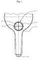
- in einer Teilansicht von oben einen Brausekopf, an dessen Oberseite ein Tastenfeld zur Einstellung von Strahlarten vorgesehen ist;
- Fig. 2 und 3
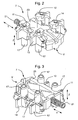
- jeweils unterschiedliche perspektivische Ansichten eines unterhalb des Tastenfeldes angeordneten Tastmechanismus;
- Fig. 4
- den Tastmechanismus in einer Ansicht von oben;
- Fig. 5 bis 10
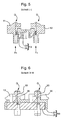
- jeweils Schnittansichten entlang der Schnittebenen I-I und II-II aus der
Fig. 4 , anhand derer unterschiedliche Betriebszustände des Tastmechanismus veranschaulicht sind; - Fig. 11
- ein federnd gelagertes Verriegelungselement des Steuerschlittens in Alleinstellung; und
- Fig. 12
- ein Tastelement in Alleinstellung.
- In der
Fig. 1 ist ein Brausekopf einer Sanitärbrause dargestellt. Der Brausekopf weist an seiner Oberseite ein Tastenfeld 1 mit vier Tastern 2 bis 5 auf, mit deren Hilfe unterschiedliche Strahlarten beliebig miteinander und/oder getrennt voneinander anwendbar sind. Die Taster 2 bis 5 des Tastenfeldes 1 sind unter Zwischenschaltung eines anhand der folgenden Figuren beschriebenen Tastmechanismus 7 in Wirkverbindung mit nicht dargestellten Stellventilen, mit deren Hilfe Strömungswege im Brausekopf zur Einstellung der Brausestrahlart geöffnet oder geschlossen werden. Die Taster 2 bis 5 sind manuell druckbetätigbar, wobei der Tastmechanismus 7 so ausgelegt ist, dass stets einer der Taster 2 bis 5 in seiner Offenposition O gehalten ist, um eine übermäßige Druckbeaufschlagung des an sich nicht druckbeständig ausgeführten Brauseschlauchs 9 zu vermeiden. Zur Rückstellung von eingedrückten Tastern 2 bis 5 wird einer der Taster bis in eine später beschriebene Freigabeposition F überdrückt, in der - mit Ausnahme des manuell eingedrückten Tasters - die anderen Taster wieder in die Ausgangslage, das heißt in die Geschlossenposition G, zurückspringen. Der in die Freigabeposition F eingedrückte Taster verbleibt demgegenüber beim Rückführen in seiner Offenposition O, um die vorerwähnte Druckbelastung des Brauseschlauches 9 zu vermeiden. - In den
Fig. 2 und 3 ist der Tastmechanismus 7 jeweils in unterschiedlicher perspektivischer Darstellung gezeigt. Demzufolge weist der Tastmechanismus 7 vier Tastelemente 11, 12, 13, 14 auf, die eine manuelle Druckbetätigung des jeweiligen Tasters 2 bis 5 über einen Schaft 17 bis zum nicht dargestellten Steuerventil übertragen. Die Tastelemente 11 bis 14 sind jeweils in vertikaler Richtung z hubverstellbar. Zudem sind die Tastelemente 11 bis 14 jeweils paarweise außerhalb eines in einer Bautiefenrichtung y hubverstellbaren Steuerschlittens 19 angeordnet. Der Steuerschlitten 19 ist in der Bautiefenrichtung y mittels einer Rückstellfeder 21 in eine Verriegelungsposition V (Fig. 2 und 3 ) vorgespannt und entgegen der Rückstellfeder 21 in eine Entriegelungsposition E (Fig. 10 ) verstellbar. Wie aus denFig. 5 bis 12 weiter hervorgeht, ist der Steuerschlitten 19 zweiteilig ausgeführt, und zwar mit einem bauteilsteifen, oberen Grundkörper 23 sowie einem an seiner Unterseite federnd gelagerten Verriegelungselement 25. - In den
Fig. 5 und 6 sind die einander gegenüberliegenden Tastelemente 11 und 12 des Tastmechanismus 7 in ihrer Ausgangslage, das heißt in einer Geschlossenposition G, gezeigt, in der sie mit einer Rückstellkraft FR (Fig. 5 ) gedrückt sind. In der Geschlossenposition G befindet sich eine Rastkontur 27, das heißt ein Rastnocken, des jeweiligen Tastelementes 11, 12 in einer Rastausnehmung 29 (nur in derFig. 7a gezeigt) zwischen dem Grundkörper 23 und dem Verriegelungselement 25. Der Rastnocken 27 ist bauteilsteif am Tastelement 11 angeformt. - Durch manuelle Druckbetätigung kann das Tastelement 11 von seiner in der
Fig. 5 und 6 gezeigten Geschlossenposition G über einen ersten Hubweg Δh1 in seine in denFig. 7 und 8 gezeigte Offenposition O verstellt werden. Bei der Hubbewegung in die Offenposition O drückt der bauteilsteife Rastnocken 27 des Tastelementes 11 gemäß derFig. 7a gegen eine Steuerschlitten-Gegenkontur 31, die elastisch nachgiebig verstellbar am federnd gelagerten Verriegelungselement 25 angeformt ist. Die Steuerschlitten-Gegenkontur 31 wird dabei von seiner Rastposition R (Fig. 7a ) unter Aufbau einer Rückstellkraft in seine in derFig. 7a gestrichelt angedeutete Auslöseposition A verstellt und bei Überwinden der Gegenkontur 31 wieder in seine Rastposition R rückgestellt, in der die Gegenkontur 31 vom Rastnocken 27 des Tastelementes 11 untergriffen ist (Fig. 7 ). In der Offenposition O des Tastelements 11 ist somit die Rastkontur 27 des Tastelementes 11 in Rasteingriff mit der korrespondierenden Gegenkontur 31 des federnd gelagerten Verriegelungselementes 25 des Steuerschlittens 19. - In gleicher Weise können gegebenenfalls auch die weiteren Tastelemente 12, 13, 14 in ihre Offenposition O gedrückt werden.
- Um die gegebenenfalls gedrückten Tastelemente 12, 13, 14 wieder in die Geschlossenposition G rückzuführen, kann das Tastelement 11 über einen zweiten Hubweg Δh2 von der in der
Fig. 7 gezeigten Offenposition O weiter in eine in derFig. 9 und 10 gezeigte Freigabeposition F überdrückt werden. Bei der Hubbewegung in die Freigabeposition F drückt eine rampenförmige Steuerfläche 33 (Fig. 10 ) des Tastelementes 11 gegen eine korrespondierende, ebenfalls rampenförmige Steuerfläche 35 (Fig. 10 ) des Grundkörpers 23 des Steuerschlittens 19, wodurch der Steuerschlitten 19 entgegen der Rückstellfeder 21 um einen Stellweg Δy in der Bautiefenrichtung y bis in seine Entriegelungsposition E (Fig. 10 ) verschoben wird. - Mit der Stellbewegung Δy bis in die Entriegelungsposition E drücken die am Verriegelungselement 25 angeformten Auslöseflächen 39 (
Fig. 9 und11 ) gegen die korrespondierenden bauteilsteifen Auslöseflächen 37 (Fig. 12 ) der Tastelemente 11 bis 14, wodurch die Gegenkonturen 31 am Verriegelungselement 25 von der Rastposition R elastisch nachgiebig in die Auslöseposition A (Fig. 9a ) verlagert werden. Dadurch wird der Rasteingriff zwischen den Rastkonturen 27 der Tastelemente und den Gegenkonturen 31 des Verriegelungselements 25 gelöst. Gegebenenfalls in der Offenposition O befindliche Tastelemente 12 bis 14 können daher unter Abbau der Rückstellkraft FR wieder in ihre Geschlossenposition G zurückspringen. - Die Rückstellung in die Geschlossenposition G erfolgt mit Ausnahme des bis in die Freigabeposition F druckbetätigten Tastelementes 11. Durch das Hochführen des in die Freigabeposition F druckbetätigten Tastelementes 11 verlagert sich nämlich der Steuerschlitten 19 bereits wieder aus seiner Entriegelungsposition E. Damit kann die Rastkontur 27 nicht mehr an der Gegenkontur 31 vorbeigeführt werden, sondern verrastet diese abermals mit der Gegenkontur 31 des Steuerschlittens 19, so dass das Tastelement 11 in der Offenposition O gehalten wird.
-
- 1
- Tastenfeld
- 2 bis 5
- Taster
- 7
- Tastmechanismus
- 9
- Schlauch
- 11 bis 14
- Tastelemente
- 17
- Schaft
- 19
- Steuerschlitten
- 21
- Rückstellfeder
- 23
- Grundkörper
- 25
- federnd gelagertes Verriegelungselement
- 27
- Rastkontur
- 29
- Rastausnehmung
- 31
- Gegenkontur
- 33
- Tastelement-Steuerfläche
- 35
- Grundkörper-Steuerfläche
- 37
- Tastelement-Auslösefläche
- 39
- Verriegelungselement-Auslösefläche
- G
- Geschlossenposition
- O
- Offenposition
- F
- Freigabeposition
- FR
- Rückstellkraft
- Δh1
- erster Hubweg
- Δh2
- zweiter Hubweg
- z
- Vertikalrichtung
- y
- Bautiefenrichtung
- x
- Seitenrichtung
Claims (10)
- Sanitärbrause mit einem Brausekopf mit einem zumindest zwei Tastelemente (11 bis 14) aufweisenden Tastenfeld (1), bei deren manueller Druckbetätigung eine Brausenstrahlart änderbar ist, wobei jeder der Tastelemente (11 bis 14) in eine Geschlossenposition (G) federvorgespannt ist, in der ein Strömungsweg im Brausekopf geschlossen ist, und über einen Hubweg (Δh) in eine Offenposition (O) drückbar ist, in der der Strömungsweg geöffnet ist und in der eine am Tastelement (11 bis 14) angeformte Rastkontur (27) in lösbarem Rasteingriff mit einer Gegenkontur (31) eines verstellbaren Steuerschlittens (19) ist, der zum Lösen des Rasteingriffs in eine Entriegelungsposition (E) verstellbar ist, in der die Tastelement-Rastkontur (27) und die Steuerschlitten-Gegenkontur (31) außer Eingriff sind, dadurch gekennzeichnet, dass die Rastkontur (27) bauteilsteif am jeweiligen Tastelement (11 bis 14) ausgebildet ist und die Gegenkontur (31) elastisch nachgiebig verstellbar am Steuerschlitten (19) ausgebildet ist, so dass bei einem Tastvorgang von der Geschlossen- in die Offenposition (G, O) die Steuerschlitten-Gegenkontur (31) unter elastischer Verformung (B) mit der bauteilsteifen Tastelement-Rastkontur (27) in Rasteingriff bringbar ist.
- Sanitärbrause nach Anspruch 1, dadurch gekennzeichnet, dass der Hubweg (Δh) des Tastelements in einen ersten Hubweg (Δh1) zwischen der Geschlossenposition (G) und der Offenposition (O) sowie in einen folgenden zweiten Hubweg (Δh2) von der Offenposition (O) in eine Freigabeposition (F) aufgeteilt ist, und dass insbesondere in der Freigabeposition (F) zum Lösen des Rasteingriffs eine Tastelement-Steuerfläche (33) den Steuerschlitten (19) in die Entriegelungsposition (E) drückt.
- Sanitärbrause nach Anspruch 1 oder 2, dadurch gekennzeichnet, dass in der Entriegelungsposition (E) des Steuerschlittens (19) eine bauteilsteif am Tastelement (11 bis 14) angeformte Auslösefläche (37) die Steuerschlitten-Gegenkontur (31) von der Rastposition (R) in die Auslöseposition (A) drückt, in der der Rasteingriff zwischen der Steuerschlitten-Gegenkontur (31) und der Tastelement-Rastkontur (27) gelöst ist.
- Sanitärbrause nach einem der vorhergehenden Ansprüche, dadurch gekennzeichnet, dass der Steuerschlitten (19) wenigstens zweiteilig ausgeführt ist, und zwar mit einem bauteilsteifen Grundkörper (23) und wenigstens einem federnd gelagerten Verriegelungselement (25).
- Sanitärbrause nach Anspruch 4, dadurch gekennzeichnet, dass am federnd gelagerten Verriegelungselement (25) des Steuerschlittens (19) die Steuerschlitten-Gegenkontur (31) ausgebildet ist.
- Sanitärbrause nach Anspruch 4 oder 5, dadurch gekennzeichnet, dass am federnd gelagerten Verriegelungselement (25) des Steuerschlittens (19) eine mit der Tastelement-Auslösefläche (37) korrespondierende Auslösefläche (39) ausgebildet ist.
- Sanitärbrause nach Anspruch 4, 5 oder 6, dadurch gekennzeichnet, dass der Grundkörper (23) des Steuerschlittens (19) eine Steuerfläche (35) aufweist, gegen die in der Freigabeposition (F) des Tastenelements (11 bis 14) dessen Tastelement-Steuerfläche (33) drückt.
- Sanitärbrause nach einem der Ansprüche 2 bis 7, dadurch gekennzeichnet, dass zum Rückstellen des ersten Tastenelements (11) von seiner Offenposition (O) in seine Geschlossenposition (G) das zweite Tastelement (12,13,14) bis in seine Freigabeposition (F) drückbar ist.
- Sanitärbrause nach einem der vorhergehenden Ansprüche, dadurch gekennzeichnet, dass die für jedes Tastelement (11 bis 14) vorgesehenen Steuerschlitten-Gegenkonturen (31) und/oder Auslöseflächen (39) an einem gemeinsamen, einteilig oder mehrteilig ausgebildeten federnd gelagerten Verriegelungselement (25) ausgebildet sind.
- Brausekopf für eine Sanitärbrause nach einem der vorhergehenden Ansprüche.
Applications Claiming Priority (1)
| Application Number | Priority Date | Filing Date | Title |
|---|---|---|---|
| DE201310006601 DE102013006601B4 (de) | 2013-04-17 | 2013-04-17 | Sanitärbrause mit einem Brausekopf |
Publications (2)
| Publication Number | Publication Date |
|---|---|
| EP2792414A1 true EP2792414A1 (de) | 2014-10-22 |
| EP2792414B1 EP2792414B1 (de) | 2016-10-12 |
Family
ID=50289362
Family Applications (1)
| Application Number | Title | Priority Date | Filing Date |
|---|---|---|---|
| EP14000986.1A Not-in-force EP2792414B1 (de) | 2013-04-17 | 2014-03-18 | Sanitärbrause mit einem Brausekopf |
Country Status (2)
| Country | Link |
|---|---|
| EP (1) | EP2792414B1 (de) |
| DE (1) | DE102013006601B4 (de) |
Citations (3)
| Publication number | Priority date | Publication date | Assignee | Title |
|---|---|---|---|---|
| WO2012089136A1 (zh) * | 2010-12-30 | 2012-07-05 | 厦门松霖科技有限公司 | 拼接花洒 |
| DE102011017434A1 (de) | 2011-04-18 | 2012-10-18 | Grohe Ag | Brause oder Handbrause |
| JP5141999B1 (ja) * | 2012-03-16 | 2013-02-13 | Toto株式会社 | 水路切換装置及びそれを備えたハンドシャワーヘッド |
Family Cites Families (2)
| Publication number | Priority date | Publication date | Assignee | Title |
|---|---|---|---|---|
| US9050612B2 (en) * | 2009-03-19 | 2015-06-09 | Delta Faucet Company | Shower device with independently operating valves |
| WO2012045276A1 (zh) * | 2010-10-09 | 2012-04-12 | 厦门松霖科技有限公司 | 按钮切换出水机构及其切换方法 |
-
2013
- 2013-04-17 DE DE201310006601 patent/DE102013006601B4/de not_active Expired - Fee Related
-
2014
- 2014-03-18 EP EP14000986.1A patent/EP2792414B1/de not_active Not-in-force
Patent Citations (3)
| Publication number | Priority date | Publication date | Assignee | Title |
|---|---|---|---|---|
| WO2012089136A1 (zh) * | 2010-12-30 | 2012-07-05 | 厦门松霖科技有限公司 | 拼接花洒 |
| DE102011017434A1 (de) | 2011-04-18 | 2012-10-18 | Grohe Ag | Brause oder Handbrause |
| JP5141999B1 (ja) * | 2012-03-16 | 2013-02-13 | Toto株式会社 | 水路切換装置及びそれを備えたハンドシャワーヘッド |
Also Published As
| Publication number | Publication date |
|---|---|
| DE102013006601B4 (de) | 2015-01-08 |
| EP2792414B1 (de) | 2016-10-12 |
| DE102013006601A1 (de) | 2014-10-23 |
Similar Documents
| Publication | Publication Date | Title |
|---|---|---|
| EP3740708B1 (de) | Ventilbetätigungsvorrichtung | |
| EP2941779B1 (de) | Tastenmodul und aufsteckelement für ein tastenmodul | |
| EP3153064A1 (de) | Vorrichtung zur lösbaren verbindung eines in einem möbelkorpus eines möbelteils über eine führungseinheit beweglich geführten möbelauszugs mit der führungseinheit | |
| DE102008017019A1 (de) | Gelenkbeschlag für Kraftfahrzeugsitze und mit einer Ronde | |
| DE102005007887B3 (de) | Vorrichtung zur Betätigung einer Sanitärarmatur | |
| EP2792414B1 (de) | Sanitärbrause mit einem Brausekopf | |
| EP3184706B1 (de) | Haltevorrichtung mit entlang einer haltestange verschieblichem halteschieber | |
| EP2792415B1 (de) | Sanitärbrause mit einem Brausekopf | |
| EP3384995A1 (de) | Umschaltvorrichtung für eine sanitärarmatur | |
| EP2781811B1 (de) | Ventileinrichtung | |
| EP1114717B1 (de) | Handbetätigte Presse mit Not-Entriegelungsknopf | |
| DE202013102552U1 (de) | Verstellbarer Säulenverkleidungs-Haltegriff für ein Fahrzeug | |
| EP3934930B1 (de) | Schaltungsanordnung | |
| EP2711083B1 (de) | Brausekopf | |
| DE102006055967B4 (de) | Verstelleinheit für die Höhenverstellung eines Sitzes | |
| EP4308833A1 (de) | Betätigungsvorrichtung zum betätigen von ventilen | |
| EP1855299A2 (de) | Not-Aus-Schaltgerät | |
| DE2714820B2 (de) | Schalttastatur | |
| EP1842972A1 (de) | Sanitärarmatur mit versenkbarem Auslauf | |
| EP4264096A1 (de) | Betätigungsvorrichtung zur verwendung in sanitärinstallationen | |
| DE2047758C3 (de) | Betätigungsvorrichtung, insbesondere für einen elektrischen Schalter, mit einem durch eine Rasteinrichtung feststellbaren Betätigungsorgan | |
| DE102021124754A1 (de) | Betätigungsvorrichtung zur Verwendung mit einer Sanitärinstallation | |
| WO2023046380A1 (de) | Betätigungsvorrichtung zur verwendung mit einer sanitärinstallation | |
| DE102016118087A1 (de) | Düsenpistole und Hebelarretierungsmechanismus | |
| DE102021106657A1 (de) | Betätigungsvorrichtung zur Verwendung in Sanitärinstallationen |
Legal Events
| Date | Code | Title | Description |
|---|---|---|---|
| PUAI | Public reference made under article 153(3) epc to a published international application that has entered the european phase |
Free format text: ORIGINAL CODE: 0009012 |
|
| 17P | Request for examination filed |
Effective date: 20140318 |
|
| AK | Designated contracting states |
Kind code of ref document: A1 Designated state(s): AL AT BE BG CH CY CZ DE DK EE ES FI FR GB GR HR HU IE IS IT LI LT LU LV MC MK MT NL NO PL PT RO RS SE SI SK SM TR |
|
| AX | Request for extension of the european patent |
Extension state: BA ME |
|
| R17P | Request for examination filed (corrected) |
Effective date: 20150421 |
|
| RBV | Designated contracting states (corrected) |
Designated state(s): AL AT BE BG CH CY CZ DE DK EE ES FI FR GB GR HR HU IE IS IT LI LT LU LV MC MK MT NL NO PL PT RO RS SE SI SK SM TR |
|
| GRAP | Despatch of communication of intention to grant a patent |
Free format text: ORIGINAL CODE: EPIDOSNIGR1 |
|
| INTG | Intention to grant announced |
Effective date: 20160524 |
|
| GRAS | Grant fee paid |
Free format text: ORIGINAL CODE: EPIDOSNIGR3 |
|
| GRAA | (expected) grant |
Free format text: ORIGINAL CODE: 0009210 |
|
| AK | Designated contracting states |
Kind code of ref document: B1 Designated state(s): AL AT BE BG CH CY CZ DE DK EE ES FI FR GB GR HR HU IE IS IT LI LT LU LV MC MK MT NL NO PL PT RO RS SE SI SK SM TR |
|
| REG | Reference to a national code |
Ref country code: GB Ref legal event code: FG4D Free format text: NOT ENGLISH |
|
| REG | Reference to a national code |
Ref country code: CH Ref legal event code: EP |
|
| REG | Reference to a national code |
Ref country code: AT Ref legal event code: REF Ref document number: 836007 Country of ref document: AT Kind code of ref document: T Effective date: 20161015 |
|
| REG | Reference to a national code |
Ref country code: IE Ref legal event code: FG4D Free format text: LANGUAGE OF EP DOCUMENT: GERMAN |
|
| REG | Reference to a national code |
Ref country code: DE Ref legal event code: R096 Ref document number: 502014001654 Country of ref document: DE |
|
| REG | Reference to a national code |
Ref country code: LT Ref legal event code: MG4D |
|
| REG | Reference to a national code |
Ref country code: NL Ref legal event code: MP Effective date: 20161012 |
|
| PG25 | Lapsed in a contracting state [announced via postgrant information from national office to epo] |
Ref country code: LV Free format text: LAPSE BECAUSE OF FAILURE TO SUBMIT A TRANSLATION OF THE DESCRIPTION OR TO PAY THE FEE WITHIN THE PRESCRIBED TIME-LIMIT Effective date: 20161012 |
|
| REG | Reference to a national code |
Ref country code: FR Ref legal event code: PLFP Year of fee payment: 4 |
|
| PG25 | Lapsed in a contracting state [announced via postgrant information from national office to epo] |
Ref country code: SE Free format text: LAPSE BECAUSE OF FAILURE TO SUBMIT A TRANSLATION OF THE DESCRIPTION OR TO PAY THE FEE WITHIN THE PRESCRIBED TIME-LIMIT Effective date: 20161012 Ref country code: LT Free format text: LAPSE BECAUSE OF FAILURE TO SUBMIT A TRANSLATION OF THE DESCRIPTION OR TO PAY THE FEE WITHIN THE PRESCRIBED TIME-LIMIT Effective date: 20161012 Ref country code: NO Free format text: LAPSE BECAUSE OF FAILURE TO SUBMIT A TRANSLATION OF THE DESCRIPTION OR TO PAY THE FEE WITHIN THE PRESCRIBED TIME-LIMIT Effective date: 20170112 Ref country code: GR Free format text: LAPSE BECAUSE OF FAILURE TO SUBMIT A TRANSLATION OF THE DESCRIPTION OR TO PAY THE FEE WITHIN THE PRESCRIBED TIME-LIMIT Effective date: 20170113 |
|
| PG25 | Lapsed in a contracting state [announced via postgrant information from national office to epo] |
Ref country code: PL Free format text: LAPSE BECAUSE OF FAILURE TO SUBMIT A TRANSLATION OF THE DESCRIPTION OR TO PAY THE FEE WITHIN THE PRESCRIBED TIME-LIMIT Effective date: 20161012 Ref country code: PT Free format text: LAPSE BECAUSE OF FAILURE TO SUBMIT A TRANSLATION OF THE DESCRIPTION OR TO PAY THE FEE WITHIN THE PRESCRIBED TIME-LIMIT Effective date: 20170213 Ref country code: IS Free format text: LAPSE BECAUSE OF FAILURE TO SUBMIT A TRANSLATION OF THE DESCRIPTION OR TO PAY THE FEE WITHIN THE PRESCRIBED TIME-LIMIT Effective date: 20170212 Ref country code: ES Free format text: LAPSE BECAUSE OF FAILURE TO SUBMIT A TRANSLATION OF THE DESCRIPTION OR TO PAY THE FEE WITHIN THE PRESCRIBED TIME-LIMIT Effective date: 20161012 Ref country code: RS Free format text: LAPSE BECAUSE OF FAILURE TO SUBMIT A TRANSLATION OF THE DESCRIPTION OR TO PAY THE FEE WITHIN THE PRESCRIBED TIME-LIMIT Effective date: 20161012 Ref country code: HR Free format text: LAPSE BECAUSE OF FAILURE TO SUBMIT A TRANSLATION OF THE DESCRIPTION OR TO PAY THE FEE WITHIN THE PRESCRIBED TIME-LIMIT Effective date: 20161012 Ref country code: FI Free format text: LAPSE BECAUSE OF FAILURE TO SUBMIT A TRANSLATION OF THE DESCRIPTION OR TO PAY THE FEE WITHIN THE PRESCRIBED TIME-LIMIT Effective date: 20161012 Ref country code: NL Free format text: LAPSE BECAUSE OF FAILURE TO SUBMIT A TRANSLATION OF THE DESCRIPTION OR TO PAY THE FEE WITHIN THE PRESCRIBED TIME-LIMIT Effective date: 20161012 |
|
| REG | Reference to a national code |
Ref country code: DE Ref legal event code: R097 Ref document number: 502014001654 Country of ref document: DE |
|
| PG25 | Lapsed in a contracting state [announced via postgrant information from national office to epo] |
Ref country code: EE Free format text: LAPSE BECAUSE OF FAILURE TO SUBMIT A TRANSLATION OF THE DESCRIPTION OR TO PAY THE FEE WITHIN THE PRESCRIBED TIME-LIMIT Effective date: 20161012 Ref country code: SK Free format text: LAPSE BECAUSE OF FAILURE TO SUBMIT A TRANSLATION OF THE DESCRIPTION OR TO PAY THE FEE WITHIN THE PRESCRIBED TIME-LIMIT Effective date: 20161012 Ref country code: DK Free format text: LAPSE BECAUSE OF FAILURE TO SUBMIT A TRANSLATION OF THE DESCRIPTION OR TO PAY THE FEE WITHIN THE PRESCRIBED TIME-LIMIT Effective date: 20161012 Ref country code: CZ Free format text: LAPSE BECAUSE OF FAILURE TO SUBMIT A TRANSLATION OF THE DESCRIPTION OR TO PAY THE FEE WITHIN THE PRESCRIBED TIME-LIMIT Effective date: 20161012 Ref country code: RO Free format text: LAPSE BECAUSE OF FAILURE TO SUBMIT A TRANSLATION OF THE DESCRIPTION OR TO PAY THE FEE WITHIN THE PRESCRIBED TIME-LIMIT Effective date: 20161012 |
|
| PLBE | No opposition filed within time limit |
Free format text: ORIGINAL CODE: 0009261 |
|
| STAA | Information on the status of an ep patent application or granted ep patent |
Free format text: STATUS: NO OPPOSITION FILED WITHIN TIME LIMIT |
|
| PG25 | Lapsed in a contracting state [announced via postgrant information from national office to epo] |
Ref country code: SM Free format text: LAPSE BECAUSE OF FAILURE TO SUBMIT A TRANSLATION OF THE DESCRIPTION OR TO PAY THE FEE WITHIN THE PRESCRIBED TIME-LIMIT Effective date: 20161012 Ref country code: IT Free format text: LAPSE BECAUSE OF FAILURE TO SUBMIT A TRANSLATION OF THE DESCRIPTION OR TO PAY THE FEE WITHIN THE PRESCRIBED TIME-LIMIT Effective date: 20161012 Ref country code: BG Free format text: LAPSE BECAUSE OF FAILURE TO SUBMIT A TRANSLATION OF THE DESCRIPTION OR TO PAY THE FEE WITHIN THE PRESCRIBED TIME-LIMIT Effective date: 20170112 |
|
| 26N | No opposition filed |
Effective date: 20170713 |
|
| REG | Reference to a national code |
Ref country code: CH Ref legal event code: PL |
|
| PG25 | Lapsed in a contracting state [announced via postgrant information from national office to epo] |
Ref country code: SI Free format text: LAPSE BECAUSE OF FAILURE TO SUBMIT A TRANSLATION OF THE DESCRIPTION OR TO PAY THE FEE WITHIN THE PRESCRIBED TIME-LIMIT Effective date: 20161012 Ref country code: MC Free format text: LAPSE BECAUSE OF FAILURE TO SUBMIT A TRANSLATION OF THE DESCRIPTION OR TO PAY THE FEE WITHIN THE PRESCRIBED TIME-LIMIT Effective date: 20161012 |
|
| REG | Reference to a national code |
Ref country code: IE Ref legal event code: MM4A |
|
| PG25 | Lapsed in a contracting state [announced via postgrant information from national office to epo] |
Ref country code: LU Free format text: LAPSE BECAUSE OF NON-PAYMENT OF DUE FEES Effective date: 20170318 |
|
| PG25 | Lapsed in a contracting state [announced via postgrant information from national office to epo] |
Ref country code: IE Free format text: LAPSE BECAUSE OF NON-PAYMENT OF DUE FEES Effective date: 20170318 Ref country code: CH Free format text: LAPSE BECAUSE OF NON-PAYMENT OF DUE FEES Effective date: 20170331 Ref country code: LI Free format text: LAPSE BECAUSE OF NON-PAYMENT OF DUE FEES Effective date: 20170331 |
|
| REG | Reference to a national code |
Ref country code: BE Ref legal event code: MM Effective date: 20170331 |
|
| REG | Reference to a national code |
Ref country code: FR Ref legal event code: PLFP Year of fee payment: 5 |
|
| PG25 | Lapsed in a contracting state [announced via postgrant information from national office to epo] |
Ref country code: BE Free format text: LAPSE BECAUSE OF NON-PAYMENT OF DUE FEES Effective date: 20170331 |
|
| PG25 | Lapsed in a contracting state [announced via postgrant information from national office to epo] |
Ref country code: MT Free format text: LAPSE BECAUSE OF FAILURE TO SUBMIT A TRANSLATION OF THE DESCRIPTION OR TO PAY THE FEE WITHIN THE PRESCRIBED TIME-LIMIT Effective date: 20161012 |
|
| GBPC | Gb: european patent ceased through non-payment of renewal fee |
Effective date: 20180318 |
|
| PG25 | Lapsed in a contracting state [announced via postgrant information from national office to epo] |
Ref country code: GB Free format text: LAPSE BECAUSE OF NON-PAYMENT OF DUE FEES Effective date: 20180318 |
|
| PGFP | Annual fee paid to national office [announced via postgrant information from national office to epo] |
Ref country code: DE Payment date: 20190321 Year of fee payment: 6 Ref country code: FR Payment date: 20190322 Year of fee payment: 6 |
|
| PG25 | Lapsed in a contracting state [announced via postgrant information from national office to epo] |
Ref country code: HU Free format text: LAPSE BECAUSE OF FAILURE TO SUBMIT A TRANSLATION OF THE DESCRIPTION OR TO PAY THE FEE WITHIN THE PRESCRIBED TIME-LIMIT; INVALID AB INITIO Effective date: 20140318 |
|
| PG25 | Lapsed in a contracting state [announced via postgrant information from national office to epo] |
Ref country code: CY Free format text: LAPSE BECAUSE OF FAILURE TO SUBMIT A TRANSLATION OF THE DESCRIPTION OR TO PAY THE FEE WITHIN THE PRESCRIBED TIME-LIMIT Effective date: 20161012 |
|
| PG25 | Lapsed in a contracting state [announced via postgrant information from national office to epo] |
Ref country code: MK Free format text: LAPSE BECAUSE OF FAILURE TO SUBMIT A TRANSLATION OF THE DESCRIPTION OR TO PAY THE FEE WITHIN THE PRESCRIBED TIME-LIMIT Effective date: 20161012 |
|
| PG25 | Lapsed in a contracting state [announced via postgrant information from national office to epo] |
Ref country code: TR Free format text: LAPSE BECAUSE OF FAILURE TO SUBMIT A TRANSLATION OF THE DESCRIPTION OR TO PAY THE FEE WITHIN THE PRESCRIBED TIME-LIMIT Effective date: 20161012 |
|
| PG25 | Lapsed in a contracting state [announced via postgrant information from national office to epo] |
Ref country code: AL Free format text: LAPSE BECAUSE OF FAILURE TO SUBMIT A TRANSLATION OF THE DESCRIPTION OR TO PAY THE FEE WITHIN THE PRESCRIBED TIME-LIMIT Effective date: 20161012 |
|
| REG | Reference to a national code |
Ref country code: AT Ref legal event code: MM01 Ref document number: 836007 Country of ref document: AT Kind code of ref document: T Effective date: 20190318 |
|
| REG | Reference to a national code |
Ref country code: DE Ref legal event code: R119 Ref document number: 502014001654 Country of ref document: DE |
|
| PG25 | Lapsed in a contracting state [announced via postgrant information from national office to epo] |
Ref country code: AT Free format text: LAPSE BECAUSE OF NON-PAYMENT OF DUE FEES Effective date: 20190318 |
|
| PG25 | Lapsed in a contracting state [announced via postgrant information from national office to epo] |
Ref country code: DE Free format text: LAPSE BECAUSE OF NON-PAYMENT OF DUE FEES Effective date: 20201001 Ref country code: FR Free format text: LAPSE BECAUSE OF NON-PAYMENT OF DUE FEES Effective date: 20200331 |