EP2711083B1 - Brausekopf - Google Patents
Brausekopf Download PDFInfo
- Publication number
- EP2711083B1 EP2711083B1 EP13184900.2A EP13184900A EP2711083B1 EP 2711083 B1 EP2711083 B1 EP 2711083B1 EP 13184900 A EP13184900 A EP 13184900A EP 2711083 B1 EP2711083 B1 EP 2711083B1
- Authority
- EP
- European Patent Office
- Prior art keywords
- jet
- shower head
- switching device
- jet disk
- disk
- Prior art date
- Legal status (The legal status is an assumption and is not a legal conclusion. Google has not performed a legal analysis and makes no representation as to the accuracy of the status listed.)
- Active
Links
- XLYOFNOQVPJJNP-UHFFFAOYSA-N water Substances O XLYOFNOQVPJJNP-UHFFFAOYSA-N 0.000 claims description 13
- 238000006073 displacement reaction Methods 0.000 claims description 3
- 230000006835 compression Effects 0.000 description 3
- 238000007906 compression Methods 0.000 description 3
- 230000005540 biological transmission Effects 0.000 description 2
- 230000001419 dependent effect Effects 0.000 description 1
- 230000000994 depressogenic effect Effects 0.000 description 1
- 238000011161 development Methods 0.000 description 1
- 230000018109 developmental process Effects 0.000 description 1
- 230000002093 peripheral effect Effects 0.000 description 1
- 239000007921 spray Substances 0.000 description 1
- 230000001960 triggered effect Effects 0.000 description 1
Images


Classifications
-
- B—PERFORMING OPERATIONS; TRANSPORTING
- B05—SPRAYING OR ATOMISING IN GENERAL; APPLYING FLUENT MATERIALS TO SURFACES, IN GENERAL
- B05B—SPRAYING APPARATUS; ATOMISING APPARATUS; NOZZLES
- B05B1/00—Nozzles, spray heads or other outlets, with or without auxiliary devices such as valves, heating means
- B05B1/14—Nozzles, spray heads or other outlets, with or without auxiliary devices such as valves, heating means with multiple outlet openings; with strainers in or outside the outlet opening
- B05B1/18—Roses; Shower heads
- B05B1/185—Roses; Shower heads characterised by their outlet element; Mounting arrangements therefor
-
- B—PERFORMING OPERATIONS; TRANSPORTING
- B05—SPRAYING OR ATOMISING IN GENERAL; APPLYING FLUENT MATERIALS TO SURFACES, IN GENERAL
- B05B—SPRAYING APPARATUS; ATOMISING APPARATUS; NOZZLES
- B05B1/00—Nozzles, spray heads or other outlets, with or without auxiliary devices such as valves, heating means
- B05B1/14—Nozzles, spray heads or other outlets, with or without auxiliary devices such as valves, heating means with multiple outlet openings; with strainers in or outside the outlet opening
- B05B1/16—Nozzles, spray heads or other outlets, with or without auxiliary devices such as valves, heating means with multiple outlet openings; with strainers in or outside the outlet opening having selectively- effective outlets
- B05B1/1627—Nozzles, spray heads or other outlets, with or without auxiliary devices such as valves, heating means with multiple outlet openings; with strainers in or outside the outlet opening having selectively- effective outlets with a selecting mechanism comprising a gate valve, a sliding valve or a cock
- B05B1/1636—Nozzles, spray heads or other outlets, with or without auxiliary devices such as valves, heating means with multiple outlet openings; with strainers in or outside the outlet opening having selectively- effective outlets with a selecting mechanism comprising a gate valve, a sliding valve or a cock by relative rotative movement of the valve elements
- B05B1/1645—Nozzles, spray heads or other outlets, with or without auxiliary devices such as valves, heating means with multiple outlet openings; with strainers in or outside the outlet opening having selectively- effective outlets with a selecting mechanism comprising a gate valve, a sliding valve or a cock by relative rotative movement of the valve elements the outlets being rotated during selection
- B05B1/1654—Nozzles, spray heads or other outlets, with or without auxiliary devices such as valves, heating means with multiple outlet openings; with strainers in or outside the outlet opening having selectively- effective outlets with a selecting mechanism comprising a gate valve, a sliding valve or a cock by relative rotative movement of the valve elements the outlets being rotated during selection about an axis parallel to the liquid passage in the stationary valve element
-
- B—PERFORMING OPERATIONS; TRANSPORTING
- B05—SPRAYING OR ATOMISING IN GENERAL; APPLYING FLUENT MATERIALS TO SURFACES, IN GENERAL
- B05B—SPRAYING APPARATUS; ATOMISING APPARATUS; NOZZLES
- B05B1/00—Nozzles, spray heads or other outlets, with or without auxiliary devices such as valves, heating means
- B05B1/14—Nozzles, spray heads or other outlets, with or without auxiliary devices such as valves, heating means with multiple outlet openings; with strainers in or outside the outlet opening
- B05B1/18—Roses; Shower heads
Definitions
- the invention relates to a shower head with a switch between two beam exit options, as the beam or the beams can be discharged from the shower head.
- buttons on the shower head housing are known, which can be actuated, for example, radially inward. It is also known to provide rotary rings that can touch a user and operate by turning.
- the Utility Model DE 20 2010 005 256 U1 discloses a hand shower in which the jet disc forms the bottom portion of a chamber provided in a shower head chamber with one or more chamber areas and the chamber is mounted together with jet disk in the shower head housing as a rocker for selectively setting one of several possible beam shapes.
- Each jet shape corresponds to a specific rocking position of the jet disk with its interior adjoining chamber relative to the shower head housing.
- the jet disk takes a different position for each of the different possible beam shapes.
- the patent US 5,467,927 A discloses a hand shower that can switch between two possible beam shapes.
- a jet disk of the hand shower can be pressed axially against the force of a return spring from a starting position relative to the showerhead housing axially backwards or inwards and then held in this depressed position. Once the jet disc is released, it returns to its original position, which returns the hand shower to its original position Beam shape is switched.
- the publication DE 198 59 524 A1 discloses an apparatus for switching jet types in a showerhead by applying force to an actuator coupled to a jet type actuator mechanism.
- the actuator is operable in relation to the shower head by radially directed in a plane forces and, for example, formed by a shower head surrounding the adjusting ring, which is held radially displaceable on radially acting return springs on the shower head.
- the invention is based on the object to provide a very easy-to-use way to switch between different beam exit options on a shower head.
- the invention proposes a shower head with the features specified in claim 1. Further developments of the invention are the subject of dependent claims.
- the jet disk itself or the shower head acts as an actuating element.
- the jet disc is usually quite flat or slightly curved, so that the risk of slipping with soapy fingers is not given.
- the jet disk is large in most cases, so it is easy to find. This results in a new and useful way to operate a switching device within the shower head. According to the invention it is provided that the jet disc returns to its starting position after the actuation of the switching device. To re-actuate the switching device, the jet disk is pressed again.
- the switching device is formed as a continuous switching device, so that it is switched to each next operation of the jet disk in the next position, so no back-and-forth takes place, but an indexing. This is especially useful if more than two beam exit options are provided.
- the switching device can thus affect, for example, a valve to an air intake. It can be provided that the beam or the plurality Rays then emerge from the same opening.
- a second water guide is opened by the switching device, so that the rays exit after actuation of a larger number of jet outlet openings.
- a saving position in which the jets emerge from only every second jet outlet opening, while they then emerge after switching from all the jet outlet openings.
- the invention proposes several ways in which the switching device can be actuated by the pressure exerted by the user on the jet disk.
- the jet disk is designed to be displaceable relative to the shower head housing and acts on the switching device, for example a valve, directly or via a transmission by means of this displacement.
- the valve may be any known valve of conventional design.
- showerhead housing is designed to be displaceable relative to the input connection together with the jet disk. By this shift is then also acted directly or via a transmission to the switching device.
- a linear movement along the longitudinal axis of the shower head or along a perpendicular bisector with respect to the jet disk is preferred.
- the jet disk is deformable, so that therefore the pressure exerted by the user on the jet disk leads to a deformation of the jet disk, which regresses again after release. Due to the deformability, which may also be localized, the user can act on the valve device, for example on a plunger of the valve device.
- Yet another possibility proposed by the invention to actuate the switching device by engaging the jet disk, may be that the jet disk is tiltably mounted in the housing. This can be both a tilt about a fixed axis, as well as a tilt around a central point-shaped support point.
- the jet disk remains in the shifted position until it returns to its original position triggered by a second tap or press.
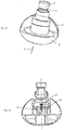
- FIG. 1 shows in perspective a shower head, which can be screwed by means of an input terminal 1 at the end of a water pipe.
- the input terminal has two wrench flats 2.
- the input terminal 1 is mechanically connected to a showerhead housing 3, which has an approximately hemispherical outer shape and is closed off by a jet disk 4 to the front side, ie on the side facing away from the input terminal 1.
- a jet disk 4 In the jet disk 4 there are two rows of concentrically arranged jet outlet openings 5, and in the middle a second group of jet outlet openings 6.
- the jet disk 4 is displaceably mounted in the showerhead housing 3 in the direction of the input connection 1, that is to say in the direction of an axis of rotation of the showerhead housing 3. This displacement can be performed by the user both during the operation of the shower head and when it is not supplied with water. This is indicated by the arrow 7 in FIG. 2 shown.
- the user presses to switch to the jet disk 4, which then can move into the showerhead housing 3 into it. This is in FIG. 2 shown.
- the disk 4 moves back into the position of FIG. 1 under the influence of a compression spring arranged in the shower head housing FIG. 3 is shown.
- the showerhead housing 3 is pivotably mounted on the spherical-shaped inner end 8 of the input terminal.
- the jet disk 4 has a transverse wall 9 at a distance from the rear side of its front wall. Between the transverse wall 9 and the front wall of the jet disk, a peripheral channel 10 is formed as an outer chamber, from which the in FIG. 1 lead out the beam exit openings 5 mentioned. This channel 10 is bounded on the one hand by an outer skirt 11 of the jet disk 4 and by an inner skirt 12. Within the inner skirt 12, a second chamber 13 is formed, from which the water can flow out of the showerhead housing 3 through the exit possibility 6.
- a wall 15 is installed parallel to the jet disk 4, pass through the two passages 16, of which the FIG. 4 only one of the passes shows.
- a passage 14 of the transverse wall 9 engages with a tubular projection in each case a passage 16 of the wall 15 a.
- a valve element 17 lying on the back of the wall 15 is rotatably mounted in the wall 15, wherein a switching mechanism with cooperating inclined surfaces is formed in the passage.
- the valve member 17 is applied by a compression spring 18 on the back of the wall 15.
- a valve opening 19 is present, which is aligned in the position shown with the passage 16.
- the jet disk 4 is characterized, see FIG. 5 , moved so far in the shower head housing 3 until the transverse wall 9 of the jet disk 4 rests against the wall 15.
- the valve element 17 is also raised by the mentioned reversing mechanism with inclined surfaces, so that the valve element 17 is no longer abutting against the inside of the wall 15.
- the compression spring 18 pushes the jet disk 4 back into the starting position via a plunger 20, and at the same time the valve element 17 twists due to the arrangement of the inclined surfaces. In the then adjusting position, see FIG.
- valve member 17 is again on the inside of the plate 15, but this time its valve opening 19 is aligned with the other passage 16 through the wall 15 and with the other passage 14 through the transverse wall 9.
- a water supply between the inlet port 1 and the inner chamber 13 made.
- the jet disk 4 is connected to the showerhead housing 23.
- the jet disk 4 is provided on the inside of its transverse wall 9 with a telescopic guide device.
- This consists of a cylindrical projection on the back of the transverse wall 9 and a cylindrical projection engaging in this cylindrical projection of an input terminal 1 connected to the intermediate element.
- a wall 25 is installed, which has two passage openings 26, of which a passage opening 26 communicates with a connection 24, which leads into an inner chamber 33 of the jet disk.
- the other passage opening 26 is in communication with a nozzle 24 which leads into the outer chamber 10 of the jet disk 4.
- the valve element 27, see also the FIG. 9 covers the one passage 26 in the position shown.
- the other passage 26 is open. The water flows out of the middle chamber 33 of the jet disk 4 through the opening provided there to the outside.
- valve member 27 is lifted from the plate 25.
- the spring pushes the jet disk 4 back together with the showerhead housing 23 into its starting position, at the same time the valve element 27 is twisted and lowered.
- the valve element 27 covers the other passage 26, the water now flows through the in FIG. 13 Right passage 26 shown in the outer chamber 10 of the jet disk 4. The switching is done.
- the invention proposes a shower head, in particular for a fixed installed shower, for example, an overhead shower before.
- the shower head has different possibilities of leakage of water from the jet disk.
- a switching device is provided. This can work in a conventional manner by means of mutually sliding bevels.
- To actuate the switching device is the jet disk itself, which is pressurized by the user against the exit direction of the water jets.
Description
- Die Erfindung bezieht sich auf einen Brausekopf mit einer Umschaltmöglichkeit zwischen zwei Strahlaustrittsmöglichkeiten, wie der Strahl oder die Strahlen aus dem Brausekopf abgegeben werden können.
- Es ist bekannt, dass aus Brauseköpfen zwei unterschiedliche Strahlarten abgegeben werden können, beispielsweise ein weicher belüfteter Strahl und ein harter Massagestrahl. Eine weitere bekannte Möglichkeit besteht darin, dass die Zahl der aktiven Strahlaustrittsöffnungen verändert werden kann. Hierzu ist eine Umschalteinrichtung erforderlich, die manuell betätigt werden muss.
- Zur Betätigung solcher Umstelleinrichtungen sind Drucktasten am Brausekopfgehäuse bekannt, die beispielsweise radial nach innen betätigt werden können. Ebenfalls bekannt ist es, Drehringe vorzusehen, die ein Benutzer anfassen und durch Drehen betätigen kann.
- Bei fest installierten Brausen, beispielsweise Kopfbrausen, kann das Problem bestehen, dass ein Benutzer das Betätigungselement für die Umstelleinrichtung nicht auf den ersten Anhieb findet. Dies gilt speziell auch dann, wenn der Benutzer die Hände eingeseift hat und damit von Betätigungselementen eventuell abrutscht.
- Die Gebrauchsmusterschrift
DE 20 2010 005 256 U1 offenbart eine Handbrause, bei der die Strahlscheibe den Bodenbereich einer in einem Brausekopfgehäuse vorgesehenen Kammer mit einem oder mehreren Kammerbereichen bildet und die Kammer samt Strahlscheibe in dem Brausekopfgehäuse als Wippe schwenkbar zur wahlweisen Einstellung einer von mehreren möglichen Strahlformen gelagert ist. Jeder Strahlform entspricht einer spezifische Wippstellung der Strahlscheibe mit ihrer innenseitig anschließenden Kammer relativ zum Brausekopfgehäuse. Somit nimmt bei dieser Handbrause die Strahlscheibe für jede der verschiedenen möglichen Strahlformen eine andere Position ein. - Die Patentschrift
US 5 467 927 A offenbart eine Handbrause, die zwischen zwei möglichen Strahlformen umschalten kann. Zum Umschalten zwischen den Strahlformen kann eine Strahlscheibe der Handbrause selbstrückstellend gegen die Kraft einer Rückstellfeder aus einer Ausgangsposition relativ zum Brausekopfgehäuse axial nach hinten bzw. innen gedrückt und dann in dieser gedrückten Stellung gehalten werden. Sobald die Strahlscheibe losgelassen wird, kehrt sie in ihre Ausgangsposition zurück, wodurch die Handbrause wieder in die ursprüngliche Strahlform umgeschaltet wird. - Die Offenlegungsschrift
DE 198 59 524 A1 offenbart eine Vorrichtung zur Umschaltung von Strahlarten in einem Brausekopf durch Krafteinwirkung auf ein Stellglied, das mit einem Stellmechanismus für die Strahlart gekoppelt ist. Das Stellglied ist in Bezug auf den Brausekopf durch in einer Ebene radial gerichtete Kräfte betätigbar und z.B. von einem den Brausekopf umgebenden Stellring gebildet, der über radial wirkende Rückstellfedern am Brausekopf radial verschiebbar gehalten ist. - Der Erfindung liegt die Aufgabe zu Grunde, eine sehr einfach zu betätigende Möglichkeit zum Umschalten zwischen verschiedenen Strahlaustrittsmöglichkeiten an einem Brausekopf zu schaffen.
- Zur Lösung dieser Aufgabe schlägt die Erfindung einen Brausekopf mit den im Anspruch 1 angegebenen Merkmalen vor. Weiterbildungen der Erfindung sind Gegenstand von Unteransprüchen.
- Erfindungsgemäß fungiert die Strahlscheibe selbst bzw. der Brausekopf als Betätigungselement. Die Strahlscheibe ist meistens ziemlich flach oder leicht gewölbt, so dass die Gefahr des Abrutschens mit seifigen Fingern nicht gegeben ist. Die Strahlscheibe ist darüber hinaus in den meisten Fällen groß, so dass sie leicht zu finden ist. Damit ergibt sich eine neue und sinnvolle Art, eine Umschalteinrichtung innerhalb des Brausekopfs zu betätigen. Erfindungsgemäß ist vorgesehen, dass die Strahlscheibe nach der Betätigung der Umschalteinrichtung in ihre Ausgangsposition zurückkehrt. Zur nochmaligen Betätigung der Umschalteinrichtung wird die Strahlscheibe erneut gedrückt.
- Gemäß einem weiteren Aspekt der Erfindung ist die Umschalteinrichtung als Fortschalteinrichtung ausgebildet, so dass sie nach jeder Betätigung der Strahlscheibe in die nächste Position umgeschaltet wird, also kein Hin- und Herschalten erfolgt, sondern ein Weiterschalten. Dies ist speziell dann sinnvoll, wenn mehr als zwei Strahlaustrittsmöglichkeiten vorgesehen sind.
- Ein Beispiel der unterschiedlichen Strahlaustrittsmöglichkeiten besteht darin, dass dem Strahl durch Betätigen der Umschalteinrichtung Luft hinzugefügt wird, die an irgendeiner geeigneten Stelle angesaugt wird. Hier kann die Umschalteinrichtung also z.B. ein Ventil zu einer Luftansaugöffnung beeinflussen. Es kann vorgesehen sein, dass der Strahl bzw. die mehreren Strahlen dann auch aus der gleichen Öffnung austreten.
- Eine weitere Möglichkeit besteht darin, dass durch die Umschalteinrichtung eine zweite Wasserführung geöffnet wird, so dass die Strahlen nach Betätigen aus einer größeren Zahl von Strahlaustrittsöffnungen austreten. Beispielsweise könnte man eine Sparstellung vorsehen, bei der die Strahlen aus nur jeder zweiten Strahlaustrittsöffnung austreten, während sie nach dem Umschalten dann aus allen Strahlaustrittsöffnungen austreten.
- Die Erfindung schlägt mehrere Möglichkeiten vor, wie durch den durch den Benutzer ausgeübten Druck auf die Strahlscheibe die Umschalteinrichtung betätigt werden kann.
- Eine erste Möglichkeit ist die, dass die Strahlscheibe gegenüber dem Brausekopfgehäuse verschiebbar ausgebildet ist und durch diese Verschiebung direkt oder über ein Getriebe auf die Umschalteinrichtung, beispielsweise ein Ventil, einwirkt.
- Bei dem Ventil kann es sich um ein beliebiges bekanntes Ventil üblicher Bauart handeln.
- Eine weitere von der Erfindung vorgeschlagene Möglichkeit besteht darin, dass das Brausekopfgehäuse zusammen mit der Strahlscheibe gegenüber dem Eingangsanschluss verschiebbar ausgebildet ist. Durch diese Verschiebung wird dann ebenfalls direkt oder über ein Getriebe auf die Umschalteinrichtung eingewirkt.
- Bevorzugt ist eine lineare Bewegung entlang der Längsachse des Brausekopfs bzw. entlang einer Mittelsenkrechten bezüglich der Strahlscheibe.
- Eine weitere von der Erfindung vorgeschlagene Möglichkeit besteht darin, dass die Strahlscheibe verformbar ist, so dass also der vom Benutzer ausgeübte Druck auf die Strahlscheibe zu einer Verformung der Strahlscheibe führt, die sich nach Loslassen wieder zurückbildet. Durch die Verformbarkeit, die auch örtlich begrenzt sein kann, kann der Benutzer auf die Ventileinrichtung einwirken, beispielsweise auf einen Stößel der Ventileinrichtung.
- Eine nochmals weitere von der Erfindung vorgeschlagene Möglichkeit, durch Angreifen an der Strahlscheibe die Umschalteinrichtung zu betätigen, kann darin bestehen, dass die Strahlscheibe in dem Gehäuse verkippbar gelagert ist. Dabei kann es sich sowohl um eine Verkippung um eine feste Achse handeln, als auch um eine Verkippung um eine zentrale punktförmige Abstützstelle.
- Je nach Art der Anordnung kann vorgesehen sein, dass die Strahlscheibe in der verschobenen Position bleibt, bis sie durch einen zweites Antippen oder Andrücken ausgelöst in ihre Ausgangsposition zurückkehrt.
- Weitere Merkmale, Einzelheiten und Vorzüge der Erfindung ergeben sich aus den Ansprüchen, deren Wortlaut durch Bezugnahme zum Inhalt der Beschreibung gemacht wird, der folgenden Beschreibung bevorzugter Ausführungsformen der Erfindung sowie anhand der Zeichnung. Hierbei zeigen:
- Figur 1
- eine perspektivische Ansicht einer Kopfbrause nach der Erfindung;
- Figur 2
- die perspektivische Ansicht während des Umschaltens;
- Figur 3
- die perspektivische Ansicht im umgeschalteten Zustand;
- Figur 4
- einen Schnitt durch die Kopfbrause in einer ersten Position entsprechend
Figur 1 ; - Figur 5
- den Schnitt durch die Kopfbrause während des Umschaltens;
- Figur 6
- den Schnitt durch die Kopfbrause im umgeschalteten Zustand entsprechend
Figur 3 ; - Figur 7
- schematisch die Ansicht einer Kopfbrause nach einer zweiten Ausführungsform;
- Figur 8
- den Schnitt durch die Kopfbrause der
Figur 7 in einer ersten Position; - Figur 9
- einen Querschnitt durch die Kopfbrause der
Figur 7 und Figur 8 ; - Figur 10
- den Zustand des Umschaltens der Kopfbrause der
Figur 7 ; - Figur 11
- einen der
Figur 8 entsprechenden Schnitt während des Umschaltens; - Figur 12
- die schematische Ansicht der Kopfbrause nach dem Umschalten;
- Figur 13
- einen der
Figur 11 entsprechenden Schnitt im umgeschalteten Zustand; - Figur 14
- einen der
Figur 9 entsprechenden Schnitt nach dem Umschalten. - Die
Figur 1 zeigt perspektivisch einen Brausekopf, der mithilfe eines Eingangsanschlusses 1 an dem Ende einer Wasserleitung angeschraubt werden kann. Zu diesem Zweck hat der Eingangsanschluss zwei Schlüsselflächen 2. Der Eingangsanschluss 1 ist mechanisch mit einem Brausekopfgehäuse 3 verbunden, das eine etwa halbkugelförmige Außenform aufweist und zur Vorderseite, also an der dem Eingangsanschluss 1 abgewandten Seite, von einer Strahlscheibe 4 abgeschlossen ist. In der Strahlscheibe 4 gibt es zwei Reihen von konzentrisch angeordneten Strahlaustrittsöffnungen 5, und in der Mitte eine zweite Gruppe von Strahlaustrittsöffnungen 6. - Die Strahlscheibe 4 ist in Richtung auf den Eingangsanschluss 1, also in Richtung einer Rotationsachse des Brausekopfgehäuses 3, verschiebbar in dem Brausekopfgehäuse 3 gelagert. Diese Verschiebung kann von dem Benutzer sowohl während des Betriebs des Brausekopfs als auch dann, wenn er nicht mit Wasser versorgt wird, durchgeführt werden. Dies ist durch den Pfeil 7 in
Figur 2 dargestellt. Der Benutzer drückt zum Umschalten auf die Strahlscheibe 4, die sich dann in das Brausekopfgehäuse 3 hinein verschieben lässt. Dies ist inFigur 2 dargestellt. Lässt der Benutzer die Strahlscheibe 4 wieder los, so bewegt sich die Scheibe 4 unter dem Einfluss einer in dem Brausekopfgehäuse angeordneten Druckfeder zurück in die Position der Figur 1, was durch dieFigur 3 dargestellt ist. - Nähere Einzelheiten zeigt der Schnitt der
Figur 4 . Durch das Innere des Eingangsanschlusses 1 gelangt das Wasser in das Innere des Brausekopfgehäuses. Das Brausekopfgehäuse 3 ist an dem kugelförmig ausgebildeten inneren Ende 8 des Eingangsanschlusses verschwenkbar gelagert. - Die Strahlscheibe 4 weist mit Abstand von der Rückseite ihrer Vorderwand eine Querwand 9 auf. Zwischen der Querwand 9 und der Vorderwand der Strahlscheibe ist ein umlaufender Kanal 10 als eine äußere Kammer gebildet, aus dem die in
Figur 1 erwähnten Strahlaustrittsöffnungen 5 herausführen. Dieser Kanal 10 ist einerseits durch eine äußere Schürze 11 der Strahlscheibe 4 als auch durch eine innere Schürze 12 begrenzt. Innerhalb der inneren Schürze 12 ist eine zweite Kammer 13 gebildet, aus der das Wasser durch die Austrittsmöglichkeit 6 aus dem Brausekopfgehäuse 3 heraus fließen kann. - In der Querwand 9 sind zwei Durchgänge ausgebildet, von denen der Schnitt der
Figur 1 einen Durchgang 14 zeigt. - In dem Brausekopfgehäuse ist parallel zur Strahlscheibe 4 eine Wand 15 installiert, durch die zwei Durchgänge 16 hindurchführen, von denen die
Figur 4 nur einen der Durchgänge zeigt. - Jeweils ein Durchgang 14 der Querwand 9 greift mit einem rohrförmigen Ansatz in jeweils einen Durchgang 16 der Wand 15 ein.
- In einer zentralen Anordnung ist in der Wand 15 ein auf der Rückseite der Wand 15 aufliegendes Ventilelement 17 drehbar gelagert, wobei in dem Durchgang ein Umschaltmechanismus mit zusammenwirkenden Schrägflächen ausgebildet ist. Das Ventilelement 17 wird von einer Druckfeder 18 auf die Rückseite der Wand 15 angelegt. In dem Ventilelement 17 ist eine Ventilöffnung 19 vorhanden, die in der dargestellten Position mit dem Durchgang 16 fluchtet. Es besteht also eine durchgehende Wasserführung zwischen dem Eingangsanschluss 1 und der Kammer 10.
- Zur Betätigung der Umschalteinrichtung drückt nun der Benutzer in Richtung des Pfeils 7 auf die Strahlscheibe 4. Die Strahlscheibe 4 wird dadurch, siehe
Figur 5 , in das Brausekopfgehäuse 3 soweit verschoben, bis die Querwand 9 der Strahlscheibe 4 an der Wand 15 anliegt. Dadurch wird das Ventilelement 17 durch den erwähnten Umschaltmechanismus mit Schrägflächen ebenfalls angehoben, so dass das Ventilelement 17 nicht mehr an der Innenseite der Wand 15 anliegt. Beim Loslassen schiebt die Druckfeder 18 über einen Stößel 20 die Strahlscheibe 4 wieder in die Ausgangsposition zurück, und gleichzeitig verdreht sich das Ventilelement 17 aufgrund der Anordnung der Schrägflächen. In der sich dann einstellenden Position, sieheFigur 4 , liegt das Ventilelement 17 wieder auf der Innenseite der Platte 15 auf, aber diesmal fluchtet seine Ventilöffnung 19 mit dem anderen Durchgang 16 durch die Wand 15 und mit dem anderen Durchgang 14 durch die Querwand 9. Hier ist jetzt eine Wasserführung zwischen dem Eingangsanschluss 1 und der inneren Kammer 13 hergestellt. - Damit ist die Umschaltung erfolgt.
- Bei der jetzt zu beschreibenden Ausführungsform, die in den
Figuren 7 bis 14 dargestellt ist, ist die Strahlscheibe 4 mit dem Brausekopfgehäuse 23 verbunden. Wie man derFigur 8 entnehmen kann, ist die Strahlscheibe 4 auf der Innenseite ihrer Querwand 9 mit einer teleskopischen Führungseinrichtung versehen. Diese besteht aus einem zylindrischen Ansatz an der Rückseite der Querwand 9 und einem in diesen zylindrischen Ansatz eingreifenden zylindrischen Ansatz eines mit dem Eingangsanschluss 1 verbundenen Zwischenelements. In diesem Zwischenelement 30 ist eine Wand 25 eingebaut, die zwei Durchgangsöffnungen 26 aufweist, von denen eine Durchgangsöffnung 26 mit einem Stutzen 24 in Verbindung steht, der in eine innere Kammer 33 der Strahlscheibe führt. Die andere Durchgangsöffnung 26 steht mit einem Stutzen 24 in Verbindung, der in die äußere Kammer 10 der Strahlscheibe 4 führt. Das Ventilelement 27, siehe auch dieFigur 9 , deckt in der dargestellten Position den einen Durchgang 26 ab. Der andere Durchgang 26 ist geöffnet. Das Wasser fließt aus der mittleren Kammer 33 der Strahlscheibe 4 durch die dort vorhandene Öffnung ins Freie. - Drückt nun der Benutzer auf die Strahlscheibe 4, so verschiebt diese sich zusammen mit dem Brausekopfgehäuse 23 in Richtung auf den Eingangsanschluss, dargestellt durch den Pfeil 7 in
Figur 10 . Man kann derFigur 10 auch entnehmen, dass das Brausekopfgehäuse 23 jetzt näher an den Eingangsanschluss 1 heranreicht. - Ähnlich wie bei der in
Figur 5 dargestellten Position, ist jetzt auch das Ventilelement 27 von der Platte 25 abgehoben. Sobald der Benutzer loslässt, drückt die Feder die Strahlscheibe 4 zusammen mit dem Brausekopfgehäuse 23 in ihre Ausgangsposition zurück, wobei sich gleichzeitig das Ventilelement 27 verdreht und absenkt. In der dadurch entstehenden Position, siehe dieFiguren 12 bis 14 , deckt das Ventilelement 27 den anderen Durchgang 26 ab, das Wasser fließt jetzt durch den inFigur 13 rechts dargestellten Durchgang 26 in die äußere Kammer 10 der Strahlscheibe 4. Die Umschaltung ist erfolgt. - Die Erfindung schlägt also einen Brausekopf, insbesondere für eine ortsfest installierte Brause, beispielsweise eine Kopfbrause, vor. Der Brausekopf hat verschiedene Möglichkeiten des Austretens von Wasser aus der Strahlscheibe. Um diese verschiedenen Möglichkeiten einzeln oder in Kombination einzuschalten, ist eine Umschaltvorrichtung vorgesehen. Diese kann in an sich bekannter Weise mithilfe von aneinander abgleitenden Schrägflächen arbeiten. Zur Betätigung der Umschalteinrichtung dient die Strahlscheibe selbst, die von dem Benutzer entgegen der Austrittsrichtung der Wasserstrahlen druckbeaufschlagt wird.
Claims (5)
- Brausekopf, insbesondere einer Kopfbrause, mit- einem Brausekopfgehäuse (3, 23),- einem Eingangsanschluss (1) für die Zuleitung des Wassers in das Brausekopfgehäuse (3, 23) und zu dessen Befestigung,- einer das Brausekopfgehäuse (3, 23) abschließenden Strahlscheibe (4, 24) mit mindestens einer Strahlaustrittsöffnung (5, 6),- mindestens einer von dem Eingangsanschluss (1) zu der Strahlscheibe (4, 24) führenden Wasserführung in dem Brausekopfgehäuse (3, 23),- mindestens zwei Strahlaustrittsmöglichkeiten aus der Strahlscheibe (4, 24) und- einer Umschalteinrichtung zum Umschalten zwischen den Strahlaustrittsmöglichkeiten, die durch Druck auf die Strahlscheibe (4, 24) betätigbar ist,- wobei die Strahlscheibe (4, 24) verformbar ausgebildet oder gegenüber dem Brausekopfgehäuse (3, 23) verschiebbar oder verkippbar gelagert ist oder wobei das Brausekopfgehäuse (3, 23) zusammen mit der Strahlscheibe verschiebbar gegenüber dem Eingangsanschluss (1) gelagert ist,- wobei die Strahlscheibe (4, 24) dafür eingerichtet ist, nach der Betätigung der Umschalteinrichtung wieder ihre Ausgangsposition vor der Betätigung der Umschalteinrichtung einzunehmen, ohne die Umschalteinrichtung erneut umschaltend zu betätigen.
- Brausekopf nach Anspruch 1, bei dem die Umschalteinrichtung zum Umschalten zwischen den Strahlaustrittsmöglichkeiten durch axiale Verschiebung des Brausekopfgehäuses betätigbar ist.
- Brausekopf nach Anspruch 1 oder 2, bei dem die Umschalteinrichtung als Fortschalteinrichtung ausgebildet ist.
- Brausekopf nach einem der vorhergehenden Ansprüche, bei dem die beiden Strahlaustrittsmöglichkeiten unterschiedliche Strahlarten sind.
- Brausekopf nach einem der vorhergehenden Ansprüche, bei dem die beiden Strahlaustrittsmöglichkeiten unterschiedlichen Strahlaustrittsöffnungen (5, 6) der Strahlscheibe (4, 24) zugeordnet sind.
Applications Claiming Priority (1)
| Application Number | Priority Date | Filing Date | Title |
|---|---|---|---|
| DE102012216960.1A DE102012216960A1 (de) | 2012-09-21 | 2012-09-21 | Brausekopf |
Publications (2)
| Publication Number | Publication Date |
|---|---|
| EP2711083A1 EP2711083A1 (de) | 2014-03-26 |
| EP2711083B1 true EP2711083B1 (de) | 2018-05-23 |
Family
ID=49212652
Family Applications (1)
| Application Number | Title | Priority Date | Filing Date |
|---|---|---|---|
| EP13184900.2A Active EP2711083B1 (de) | 2012-09-21 | 2013-09-18 | Brausekopf |
Country Status (3)
| Country | Link |
|---|---|
| US (1) | US9314801B2 (de) |
| EP (1) | EP2711083B1 (de) |
| DE (1) | DE102012216960A1 (de) |
Families Citing this family (2)
| Publication number | Priority date | Publication date | Assignee | Title |
|---|---|---|---|---|
| US10413916B1 (en) | 2018-02-23 | 2019-09-17 | Robert W. Bruce | Shower head |
| US11958065B2 (en) * | 2019-09-10 | 2024-04-16 | Kohler Co. | Direct access spray selection engine for water delivery devices |
Citations (1)
| Publication number | Priority date | Publication date | Assignee | Title |
|---|---|---|---|---|
| DE19859524A1 (de) * | 1998-12-11 | 2000-06-29 | Fraunhofer Ges Forschung | Vorrichtung zur Umschaltung der Strahlarten in einem Brausekopf |
Family Cites Families (16)
| Publication number | Priority date | Publication date | Assignee | Title |
|---|---|---|---|---|
| FR2149081A5 (de) * | 1971-07-31 | 1973-03-23 | Knapp Alfons | |
| DE9011751U1 (de) * | 1990-08-13 | 1990-10-18 | Baber, Reinhard, 6934 Neckargerach, De | |
| DE4326796A1 (de) | 1993-08-10 | 1995-02-16 | Scheffer Kludi Armaturen | Küchenbrause mit Reinigungsstiften |
| GB2281872B (en) * | 1993-09-21 | 1997-10-08 | Brand New Technology Limited | Showerhead with water-driven vibrator to provide massage effect |
| US6079747A (en) * | 1996-12-09 | 2000-06-27 | Winsor; Bradley P. | Walking attachment for in-line skate |
| US6164566A (en) * | 1999-09-15 | 2000-12-26 | Hui-Chen; Chao | Water ejecting structure of pistol nozzle |
| JP4537531B2 (ja) | 2000-04-20 | 2010-09-01 | 有限会社寿通商 | 浄水機能付きシャワーヘッド |
| US6290147B1 (en) * | 2000-09-19 | 2001-09-18 | Moen Incorporated | Pullout faucet wand button mechanism |
| AU2003293850A1 (en) | 2002-12-12 | 2004-06-30 | Hansgrohe Ag | Shower head with air introduction |
| DE10313822A1 (de) * | 2002-12-12 | 2004-07-15 | Hansgrohe Ag | Brause |
| DE10311383B4 (de) * | 2003-03-11 | 2009-05-07 | Hansgrohe Ag | Brause |
| WO2005031074A1 (ja) * | 2003-09-25 | 2005-04-07 | Inax Corporation | 水栓設備における吐水装置 |
| US7111795B2 (en) * | 2004-05-14 | 2006-09-26 | Waxman Consumer Products Group, Inc. | Revolving spray shower head |
| CN201042681Y (zh) | 2007-04-29 | 2008-04-02 | 周华松 | 花洒按摩水切换结构 |
| DE202010005256U1 (de) * | 2010-04-20 | 2011-05-26 | tenrit Sanitär GmbH & Co. KG, 33758 | Handbrause |
| CN202224260U (zh) | 2011-07-28 | 2012-05-23 | 胡泉森 | 一种按钮切换顶喷 |
-
2012
- 2012-09-21 DE DE102012216960.1A patent/DE102012216960A1/de not_active Ceased
-
2013
- 2013-09-18 US US14/030,491 patent/US9314801B2/en active Active
- 2013-09-18 EP EP13184900.2A patent/EP2711083B1/de active Active
Patent Citations (1)
| Publication number | Priority date | Publication date | Assignee | Title |
|---|---|---|---|---|
| DE19859524A1 (de) * | 1998-12-11 | 2000-06-29 | Fraunhofer Ges Forschung | Vorrichtung zur Umschaltung der Strahlarten in einem Brausekopf |
Also Published As
| Publication number | Publication date |
|---|---|
| US9314801B2 (en) | 2016-04-19 |
| DE102012216960A1 (de) | 2014-03-27 |
| CN103657899A (zh) | 2014-03-26 |
| EP2711083A1 (de) | 2014-03-26 |
| US20140084082A1 (en) | 2014-03-27 |
Similar Documents
| Publication | Publication Date | Title |
|---|---|---|
| EP3521672B1 (de) | Ventilbetätigungsvorrichtung | |
| EP0284801B1 (de) | Brausekopf | |
| DE102009008194A1 (de) | Sanitäres Abschalt-beziehungsweise Umschaltventil | |
| EP0646741A1 (de) | Leckagefrei schaltende Doppelventilanordnung | |
| DE3643320C2 (de) | ||
| DE102009008196A1 (de) | Brause mit Umsteller | |
| EP2573283B1 (de) | Auslaufelement | |
| EP2711083B1 (de) | Brausekopf | |
| CH626955A5 (de) | ||
| DE102008005834B4 (de) | Ventileinrichtung mit Handhilfsbetätigungseinrichtung | |
| DE19652079C2 (de) | Fluidbetriebenes Schlagwerk | |
| EP2422884B1 (de) | Brause mit einem Gelenk | |
| DE1805636B1 (de) | Steuerventilanordnung fuer den mechanisierten Stahlausbau unter Tage | |
| DE102012216959B4 (de) | Handbrause | |
| EP2268412B1 (de) | Brausekopf | |
| EP3384995B1 (de) | Umschaltvorrichtung für eine sanitärarmatur | |
| DE19926043B4 (de) | Verdrehsicherungseinrichtung | |
| DE60210638T2 (de) | Ventil und Schutzgehäuse für Druckflaschen | |
| EP2280783B1 (de) | Handbrause mit einem an einem handgriff angeordneten brausekopf | |
| EP3599027A1 (de) | Brause mit einer einen stössel aufweisenden umschaltvorrichtung | |
| DE102008028610B4 (de) | Fluidventil mit Zeitgeber | |
| EP2792415B1 (de) | Sanitärbrause mit einem Brausekopf | |
| DE2605758B1 (de) | Steuerventil fuer hydraulisch schreitenden strebausbau | |
| DE102013006601B4 (de) | Sanitärbrause mit einem Brausekopf | |
| EP3033555B1 (de) | Ventilbaugruppe für eine i.s.-maschine |
Legal Events
| Date | Code | Title | Description |
|---|---|---|---|
| PUAI | Public reference made under article 153(3) epc to a published international application that has entered the european phase |
Free format text: ORIGINAL CODE: 0009012 |
|
| AK | Designated contracting states |
Kind code of ref document: A1 Designated state(s): AL AT BE BG CH CY CZ DE DK EE ES FI FR GB GR HR HU IE IS IT LI LT LU LV MC MK MT NL NO PL PT RO RS SE SI SK SM TR |
|
| AX | Request for extension of the european patent |
Extension state: BA ME |
|
| 17P | Request for examination filed |
Effective date: 20140911 |
|
| RBV | Designated contracting states (corrected) |
Designated state(s): AL AT BE BG CH CY CZ DE DK EE ES FI FR GB GR HR HU IE IS IT LI LT LU LV MC MK MT NL NO PL PT RO RS SE SI SK SM TR |
|
| 17Q | First examination report despatched |
Effective date: 20170511 |
|
| GRAP | Despatch of communication of intention to grant a patent |
Free format text: ORIGINAL CODE: EPIDOSNIGR1 |
|
| INTG | Intention to grant announced |
Effective date: 20180125 |
|
| INTG | Intention to grant announced |
Effective date: 20180125 |
|
| GRAS | Grant fee paid |
Free format text: ORIGINAL CODE: EPIDOSNIGR3 |
|
| GRAA | (expected) grant |
Free format text: ORIGINAL CODE: 0009210 |
|
| AK | Designated contracting states |
Kind code of ref document: B1 Designated state(s): AL AT BE BG CH CY CZ DE DK EE ES FI FR GB GR HR HU IE IS IT LI LT LU LV MC MK MT NL NO PL PT RO RS SE SI SK SM TR |
|
| REG | Reference to a national code |
Ref country code: GB Ref legal event code: FG4D Free format text: NOT ENGLISH |
|
| REG | Reference to a national code |
Ref country code: CH Ref legal event code: EP |
|
| REG | Reference to a national code |
Ref country code: IE Ref legal event code: FG4D Free format text: LANGUAGE OF EP DOCUMENT: GERMAN |
|
| REG | Reference to a national code |
Ref country code: AT Ref legal event code: REF Ref document number: 1001102 Country of ref document: AT Kind code of ref document: T Effective date: 20180615 |
|
| REG | Reference to a national code |
Ref country code: DE Ref legal event code: R096 Ref document number: 502013010188 Country of ref document: DE |
|
| REG | Reference to a national code |
Ref country code: FR Ref legal event code: PLFP Year of fee payment: 6 |
|
| REG | Reference to a national code |
Ref country code: NL Ref legal event code: MP Effective date: 20180523 |
|
| REG | Reference to a national code |
Ref country code: LT Ref legal event code: MG4D |
|
| PG25 | Lapsed in a contracting state [announced via postgrant information from national office to epo] |
Ref country code: SE Free format text: LAPSE BECAUSE OF FAILURE TO SUBMIT A TRANSLATION OF THE DESCRIPTION OR TO PAY THE FEE WITHIN THE PRESCRIBED TIME-LIMIT Effective date: 20180523 Ref country code: LT Free format text: LAPSE BECAUSE OF FAILURE TO SUBMIT A TRANSLATION OF THE DESCRIPTION OR TO PAY THE FEE WITHIN THE PRESCRIBED TIME-LIMIT Effective date: 20180523 Ref country code: ES Free format text: LAPSE BECAUSE OF FAILURE TO SUBMIT A TRANSLATION OF THE DESCRIPTION OR TO PAY THE FEE WITHIN THE PRESCRIBED TIME-LIMIT Effective date: 20180523 Ref country code: BG Free format text: LAPSE BECAUSE OF FAILURE TO SUBMIT A TRANSLATION OF THE DESCRIPTION OR TO PAY THE FEE WITHIN THE PRESCRIBED TIME-LIMIT Effective date: 20180823 Ref country code: NO Free format text: LAPSE BECAUSE OF FAILURE TO SUBMIT A TRANSLATION OF THE DESCRIPTION OR TO PAY THE FEE WITHIN THE PRESCRIBED TIME-LIMIT Effective date: 20180823 Ref country code: FI Free format text: LAPSE BECAUSE OF FAILURE TO SUBMIT A TRANSLATION OF THE DESCRIPTION OR TO PAY THE FEE WITHIN THE PRESCRIBED TIME-LIMIT Effective date: 20180523 |
|
| PG25 | Lapsed in a contracting state [announced via postgrant information from national office to epo] |
Ref country code: RS Free format text: LAPSE BECAUSE OF FAILURE TO SUBMIT A TRANSLATION OF THE DESCRIPTION OR TO PAY THE FEE WITHIN THE PRESCRIBED TIME-LIMIT Effective date: 20180523 Ref country code: HR Free format text: LAPSE BECAUSE OF FAILURE TO SUBMIT A TRANSLATION OF THE DESCRIPTION OR TO PAY THE FEE WITHIN THE PRESCRIBED TIME-LIMIT Effective date: 20180523 Ref country code: NL Free format text: LAPSE BECAUSE OF FAILURE TO SUBMIT A TRANSLATION OF THE DESCRIPTION OR TO PAY THE FEE WITHIN THE PRESCRIBED TIME-LIMIT Effective date: 20180523 Ref country code: LV Free format text: LAPSE BECAUSE OF FAILURE TO SUBMIT A TRANSLATION OF THE DESCRIPTION OR TO PAY THE FEE WITHIN THE PRESCRIBED TIME-LIMIT Effective date: 20180523 Ref country code: GR Free format text: LAPSE BECAUSE OF FAILURE TO SUBMIT A TRANSLATION OF THE DESCRIPTION OR TO PAY THE FEE WITHIN THE PRESCRIBED TIME-LIMIT Effective date: 20180824 |
|
| PG25 | Lapsed in a contracting state [announced via postgrant information from national office to epo] |
Ref country code: SK Free format text: LAPSE BECAUSE OF FAILURE TO SUBMIT A TRANSLATION OF THE DESCRIPTION OR TO PAY THE FEE WITHIN THE PRESCRIBED TIME-LIMIT Effective date: 20180523 Ref country code: EE Free format text: LAPSE BECAUSE OF FAILURE TO SUBMIT A TRANSLATION OF THE DESCRIPTION OR TO PAY THE FEE WITHIN THE PRESCRIBED TIME-LIMIT Effective date: 20180523 Ref country code: PL Free format text: LAPSE BECAUSE OF FAILURE TO SUBMIT A TRANSLATION OF THE DESCRIPTION OR TO PAY THE FEE WITHIN THE PRESCRIBED TIME-LIMIT Effective date: 20180523 Ref country code: DK Free format text: LAPSE BECAUSE OF FAILURE TO SUBMIT A TRANSLATION OF THE DESCRIPTION OR TO PAY THE FEE WITHIN THE PRESCRIBED TIME-LIMIT Effective date: 20180523 Ref country code: RO Free format text: LAPSE BECAUSE OF FAILURE TO SUBMIT A TRANSLATION OF THE DESCRIPTION OR TO PAY THE FEE WITHIN THE PRESCRIBED TIME-LIMIT Effective date: 20180523 Ref country code: CZ Free format text: LAPSE BECAUSE OF FAILURE TO SUBMIT A TRANSLATION OF THE DESCRIPTION OR TO PAY THE FEE WITHIN THE PRESCRIBED TIME-LIMIT Effective date: 20180523 |
|
| REG | Reference to a national code |
Ref country code: DE Ref legal event code: R097 Ref document number: 502013010188 Country of ref document: DE |
|
| PG25 | Lapsed in a contracting state [announced via postgrant information from national office to epo] |
Ref country code: SM Free format text: LAPSE BECAUSE OF FAILURE TO SUBMIT A TRANSLATION OF THE DESCRIPTION OR TO PAY THE FEE WITHIN THE PRESCRIBED TIME-LIMIT Effective date: 20180523 Ref country code: IT Free format text: LAPSE BECAUSE OF FAILURE TO SUBMIT A TRANSLATION OF THE DESCRIPTION OR TO PAY THE FEE WITHIN THE PRESCRIBED TIME-LIMIT Effective date: 20180523 |
|
| PLBE | No opposition filed within time limit |
Free format text: ORIGINAL CODE: 0009261 |
|
| STAA | Information on the status of an ep patent application or granted ep patent |
Free format text: STATUS: NO OPPOSITION FILED WITHIN TIME LIMIT |
|
| PG25 | Lapsed in a contracting state [announced via postgrant information from national office to epo] |
Ref country code: MC Free format text: LAPSE BECAUSE OF FAILURE TO SUBMIT A TRANSLATION OF THE DESCRIPTION OR TO PAY THE FEE WITHIN THE PRESCRIBED TIME-LIMIT Effective date: 20180523 |
|
| REG | Reference to a national code |
Ref country code: CH Ref legal event code: PL |
|
| 26N | No opposition filed |
Effective date: 20190226 |
|
| PG25 | Lapsed in a contracting state [announced via postgrant information from national office to epo] |
Ref country code: SI Free format text: LAPSE BECAUSE OF FAILURE TO SUBMIT A TRANSLATION OF THE DESCRIPTION OR TO PAY THE FEE WITHIN THE PRESCRIBED TIME-LIMIT Effective date: 20180523 |
|
| REG | Reference to a national code |
Ref country code: BE Ref legal event code: MM Effective date: 20180930 |
|
| REG | Reference to a national code |
Ref country code: IE Ref legal event code: MM4A |
|
| PG25 | Lapsed in a contracting state [announced via postgrant information from national office to epo] |
Ref country code: LU Free format text: LAPSE BECAUSE OF NON-PAYMENT OF DUE FEES Effective date: 20180918 |
|
| PG25 | Lapsed in a contracting state [announced via postgrant information from national office to epo] |
Ref country code: IE Free format text: LAPSE BECAUSE OF NON-PAYMENT OF DUE FEES Effective date: 20180918 |
|
| PG25 | Lapsed in a contracting state [announced via postgrant information from national office to epo] |
Ref country code: BE Free format text: LAPSE BECAUSE OF NON-PAYMENT OF DUE FEES Effective date: 20180930 Ref country code: CH Free format text: LAPSE BECAUSE OF NON-PAYMENT OF DUE FEES Effective date: 20180930 Ref country code: LI Free format text: LAPSE BECAUSE OF NON-PAYMENT OF DUE FEES Effective date: 20180930 |
|
| REG | Reference to a national code |
Ref country code: AT Ref legal event code: MM01 Ref document number: 1001102 Country of ref document: AT Kind code of ref document: T Effective date: 20180918 |
|
| PG25 | Lapsed in a contracting state [announced via postgrant information from national office to epo] |
Ref country code: AL Free format text: LAPSE BECAUSE OF FAILURE TO SUBMIT A TRANSLATION OF THE DESCRIPTION OR TO PAY THE FEE WITHIN THE PRESCRIBED TIME-LIMIT Effective date: 20180523 |
|
| PG25 | Lapsed in a contracting state [announced via postgrant information from national office to epo] |
Ref country code: MT Free format text: LAPSE BECAUSE OF FAILURE TO SUBMIT A TRANSLATION OF THE DESCRIPTION OR TO PAY THE FEE WITHIN THE PRESCRIBED TIME-LIMIT Effective date: 20180523 Ref country code: AT Free format text: LAPSE BECAUSE OF NON-PAYMENT OF DUE FEES Effective date: 20180918 |
|
| PG25 | Lapsed in a contracting state [announced via postgrant information from national office to epo] |
Ref country code: TR Free format text: LAPSE BECAUSE OF FAILURE TO SUBMIT A TRANSLATION OF THE DESCRIPTION OR TO PAY THE FEE WITHIN THE PRESCRIBED TIME-LIMIT Effective date: 20180523 |
|
| PG25 | Lapsed in a contracting state [announced via postgrant information from national office to epo] |
Ref country code: PT Free format text: LAPSE BECAUSE OF FAILURE TO SUBMIT A TRANSLATION OF THE DESCRIPTION OR TO PAY THE FEE WITHIN THE PRESCRIBED TIME-LIMIT Effective date: 20180523 Ref country code: HU Free format text: LAPSE BECAUSE OF FAILURE TO SUBMIT A TRANSLATION OF THE DESCRIPTION OR TO PAY THE FEE WITHIN THE PRESCRIBED TIME-LIMIT; INVALID AB INITIO Effective date: 20130918 |
|
| PG25 | Lapsed in a contracting state [announced via postgrant information from national office to epo] |
Ref country code: CY Free format text: LAPSE BECAUSE OF FAILURE TO SUBMIT A TRANSLATION OF THE DESCRIPTION OR TO PAY THE FEE WITHIN THE PRESCRIBED TIME-LIMIT Effective date: 20180523 Ref country code: MK Free format text: LAPSE BECAUSE OF NON-PAYMENT OF DUE FEES Effective date: 20180523 |
|
| PG25 | Lapsed in a contracting state [announced via postgrant information from national office to epo] |
Ref country code: IS Free format text: LAPSE BECAUSE OF FAILURE TO SUBMIT A TRANSLATION OF THE DESCRIPTION OR TO PAY THE FEE WITHIN THE PRESCRIBED TIME-LIMIT Effective date: 20180923 |
|
| PGFP | Annual fee paid to national office [announced via postgrant information from national office to epo] |
Ref country code: GB Payment date: 20230926 Year of fee payment: 11 |
|
| PGFP | Annual fee paid to national office [announced via postgrant information from national office to epo] |
Ref country code: FR Payment date: 20230926 Year of fee payment: 11 Ref country code: DE Payment date: 20230928 Year of fee payment: 11 |