EP2791809B1 - Unified data masking, data poisoning, and data bus inversion signaling - Google Patents
Unified data masking, data poisoning, and data bus inversion signaling Download PDFInfo
- Publication number
- EP2791809B1 EP2791809B1 EP12809487.7A EP12809487A EP2791809B1 EP 2791809 B1 EP2791809 B1 EP 2791809B1 EP 12809487 A EP12809487 A EP 12809487A EP 2791809 B1 EP2791809 B1 EP 2791809B1
- Authority
- EP
- European Patent Office
- Prior art keywords
- data
- data bits
- bits
- state
- indicator signal
- Prior art date
- Legal status (The legal status is an assumption and is not a legal conclusion. Google has not performed a legal analysis and makes no representation as to the accuracy of the status listed.)
- Active
Links
Images


Classifications
-
- G—PHYSICS
- G06—COMPUTING OR CALCULATING; COUNTING
- G06F—ELECTRIC DIGITAL DATA PROCESSING
- G06F13/00—Interconnection of, or transfer of information or other signals between, memories, input/output devices or central processing units
- G06F13/38—Information transfer, e.g. on bus
- G06F13/42—Bus transfer protocol, e.g. handshake; Synchronisation
- G06F13/4204—Bus transfer protocol, e.g. handshake; Synchronisation on a parallel bus
- G06F13/4234—Bus transfer protocol, e.g. handshake; Synchronisation on a parallel bus being a memory bus
- G06F13/4239—Bus transfer protocol, e.g. handshake; Synchronisation on a parallel bus being a memory bus with asynchronous protocol
-
- Y—GENERAL TAGGING OF NEW TECHNOLOGICAL DEVELOPMENTS; GENERAL TAGGING OF CROSS-SECTIONAL TECHNOLOGIES SPANNING OVER SEVERAL SECTIONS OF THE IPC; TECHNICAL SUBJECTS COVERED BY FORMER USPC CROSS-REFERENCE ART COLLECTIONS [XRACs] AND DIGESTS
- Y02—TECHNOLOGIES OR APPLICATIONS FOR MITIGATION OR ADAPTATION AGAINST CLIMATE CHANGE
- Y02D—CLIMATE CHANGE MITIGATION TECHNOLOGIES IN INFORMATION AND COMMUNICATION TECHNOLOGIES [ICT], I.E. INFORMATION AND COMMUNICATION TECHNOLOGIES AIMING AT THE REDUCTION OF THEIR OWN ENERGY USE
- Y02D10/00—Energy efficient computing, e.g. low power processors, power management or thermal management
Definitions
- the present invention is genera:!lly directed to high speed memory systems. More particularly, the present invention is directed to improved signaling of data status within a computing system.
- a data bus is susceptible to cross talk, simultaneous switching noise, inter-symbol interference, and draws power based on the state of the data and/or frequency of data transition.
- One way to reduce these adverse effects and to prevent unnecessary power consumption is to encode the data.
- One specific form of data encoding that can be used is data bus inversion (DBI).
- Implementation of DBI includes encoding circuitry at the transmitter that assesses the relationship between data bits to be transmitted across a data bus and then decides (based on a particular DBI algorithm) if it would be advantageous to invert some or all of the data bits prior to transmission. If the data bits are inverted, an additional signal, referred to as a DBI bit, is also set at the encoding circuitry to indicate that the data bits are inverted. Typically, an extra channel is needed so that the DBI bit may be transmitted in parallel with the data bits to inform the receiving circuitry which groups of data bits have been inverted. A receiver then uses the DBI bit in conjunction with decoding circuitry to return the incoming group of data bits to their original state.
- DRAMs may be used for the main memory of a computer system, and also may be used in graphics applications.
- DRAMs may include a data masking function to mask data that is input via data input and output pins (typically called "DQ pins") from an external source.
- Data masking generally is performed in units of a single byte and is signaled through the use of a data masking bit or line. For example, in the case of a synchronous DRAM having a data path width of 16 bits, there are generally two data masking pins (typically called "DQM pins”) from which data masking signals are input.
- DQM pins data masking pins
- DQM pins comprise a lower DQM (LDQM) pin and an upper DQM (UDQM) pin.
- the LDQM pin masks data input via data input and output pins DQ0 through DQ7, e.g., the lower 8 bits of 16 bits that are input via 16 data input and output pins DQ1 through DQ15.
- the UDQM pin masks the upper 8 bits, e.g., data input via data input and output pins DQ8 through DQ15 where pins include any input/output structure for an integrated circuit (IC) device and can include pads, optical input/output structures and other conventional input/output structures.
- IC integrated circuit
- an IC memory device can include multiple pins, or lines, that indicate the status of data on a data bus, e.g., DBI and/or masking. Such a device may also use a single control line to indicate the status of a data bus, but utilize multiple clock cycles to convey multiple status states that are associated with the data.
- the international application WO2011/008394 discloses a data encoding scheme which combines DBI encoding and non-DBI encoding and uses a single indicator signal, i.e. a data mask signal to indicate the type of encoding used. The document is silent as to signaling of poisoned data.
- invention concerns a method of providing unified signaling as in independent claim 1 and a method of receiving unified data signaling as in independent claim 5.
- the invention also concerns a system for providing unified data signaling as in independent claim 8 and a system for receiving unified data signaling as in independent claim 10. Further embodiments are defined in the dependent claims.
- references to "one embodiment,” “an embodiment,” “an example embodiment,” etc. indicate that the embodiment described may include a particular feature, structure, or characteristic, but every embodiment may not necessarily include the particular feature, structure, or characteristic. Moreover, such phrases are not necessarily referring to the same embodiment. Further, when a particular feature, structure, or characteristic is described in connection with an embodiment, it is submitted that it is within the knowledge of one skilled in the art to affect such feature, structure, or characteristic in connection with other embodiments whether or not explicitly described.
- FIG. 1 is an illustration of a unified signaling system 100 including a host system 110, a storage system 120, and a data/command bus 130 that includes data bus lines 132-0 through 132-N and indicator line 134, a memory system 140, control lines 145 and an interface 150, according to an embodiment of the invention.
- Memory system 140 contains high speed memory, such as stacked DRAM or graphics double data rate memory (GDDR), but can contain any type of memory technology.
- memory system 140 contains logic for data bus inversion (DBI), as will be discussed in more detail later in this specification.
- DI data bus inversion
- Host system 110 can access data from storage system 120 and perform reads and writes of data in memory system 140.
- host system 110 accesses memory system 140 through multiple data lines, 132-0 through 132-N.
- the data carried on data lines 132-0 through 132-N can also be referred to as DQ signals, DQ byte, or DQ bits 0 through N.
- Host system 110 also monitors indicator line 134, which indicates, based on the state of an indicator signal present on indicator line 134, an attribute of the data present on data bus lines 132. Such an attribute includes that the data has been inverted, masked, or poisoned, as will be discussed in further detail.
- Interface 150 through control lines 145, controls how the data on data bus lines 132 is to be processed, for example whether or not data bus inversion or data poisoning support is enabled. Based on input from interface 150, memory system 140 will perform various functions, such as examining the data on data bus lines 132 to ascertain if the data should be inverted when the input from interface 150 indicates data bus inversion is enabled.
- indicator line 134 there is one indicator signal present on indicator line 134 for each DQ byte present on data bus lines 132.
- the indicator signal is sampled along with the DQ signals for each read and write to or from memory system 140.
- the state of the indicator signal in conjunction with special data patterns in the associated DQ byte can specify three special certain classes of data including that the data is inverted, masked, or poisoned.
- Data masking provides byte granularity data masking during a write access to memory.
- the mask suppresses an update to the memory.
- the use of data masking is controlled by interface 150 and will be further explained in relationship to data bus inversion and poisoning.
- DBI reduces the number of data signals that switch state (e.g., from low to high) on any given transfer of data, such as to and from memory system 150. If the number of data signals that switch states is minimized then the amount of necessary circuit power is reduced. This also improves signal integrity and generally reduces issues related to instantaneous current draw, e.g . di/dt, and also reduces noise due to state changes.
- DBI algorithms can limit the number of state changes to 50% of the data on the data bus. For example, for a DQ byte consisting of 8 bits/lines of data, the use of DBI can limit the number of changing states between two consecutive 8 bit DQ bytes to a maximum of 4 changing bits.
- interface 150 can be configured to support either DBI-dc or DBI-ac modes.
- DBI DBI-dc
- each group of data signals, DQ byte, on data bus lines 132 and the indicator signal on indicator line 134 is examined each cycle. If 50% or more of the data signals on data bus lines 132 with a given indicator signal on indicator line 134 are driven high, then the indicator signal is enabled, or driven high, and the associated data signals on data bus lines 132 are inverted. Otherwise, indicator signal on indicator line 134 is disabled, driven low, and the associated data signals on data bus lines 132 are not inverted.
- the indicator signal is driven high and the DQ bits are inverted resulting in three high DQ bits and one high indicator signal, for a total of four high signals.
- DBI data is transmitted on data bus lines 132 and indicator signal is disabled, or equivalently set to 0. If DBI- ac is enabled on interface 150, then each group of data signals, DQ byte, on data bus lines 132 and indicator signal on indicator line 134 is examined each cycle. If 50% or more of the data signals on data bus lines 132 with a given indicator signal on indicator line 134 are to switch, e.g., the state of a DQ bit is to be driven to a different value than the signal held in the previous cycle, then the indicator signal is enabled, or driven high, and the associated data signals on data bus lines 132 are inverted. Otherwise, indicator signal on indicator line 134 is disabled, driven low, and the associated data signals on data bus lines 132 are not inverted.
- the indicator signal is driven high and the DQ bits are inverted resulting in three switched DQ bits and at most one switched indicator signal (if the previous indicator signal was not enabled), for a total switching of four signals.
- DBI-dc is enabled on interface 150, when host system 110 writes a masked plurality of data bits, e.g. the byte in question will not be written to memory, a special encoding is used where indicator signal on indicator line 134 is enabled, set high, and DQ bits on data bus lines 132 are set to the first half of the bits are set low and the second half of the bits are set high. For example, if there are eight bits in the DQ byte then the pattern can be shown as 00001111. This encoding does not occur for any regular or unmasked data patterns.
- DBI is disabled, masked data is specified by enabling indicator signal on indicator line 134, e.g . setting the indicator signal high, and the DQ signals are in a do not care state, preferably remaining unchanged from the previous cycle for power saving purposes.
- enabling indicator signal on indicator line 134 e.g . setting the indicator signal high
- the DQ signals are in a do not care state, preferably remaining unchanged from the previous cycle for power saving purposes.
- DBI-ac is enabled on interface 150, when host system 110 writes a masked data byte, e.g. the byte, or plurality of data bits, in question will not be written to memory, a special encoding is used where indicator signal on indicator line 134 is enabled, set high, and DQ bits on data bus lines 132 are set such that the first half of the bits are switched from their previous value.
- the pattern can be shown as 00001111 which is generated by exclusive ORing the previous DQ data on data bus lines 132 with the current DQ data on data bus lines 132. This encoding does not occur for any regular or unmasked data patterns.
- Data poisoning is a system-level data integrity mechanism for storing data with uncorrectable errors.
- the poisoned state is returned to the host system 110 and indicates that the host stored the previously unreliable data.
- host system 110 is likely to maintain error-correcting code (ECC) - protected write-back caches.
- ECC error-correcting code
- this error may not be detected until the cache line is evicted.
- the data is corrupted, but the process that generated or requires this data may no longer be executing on host system 110.
- the desired behavior is to evict the corrupted data to memory and store the "poisoned state" of this data. Subsequent reads of this poisoned data from memory will signal an error to the process requesting this data.
- a write of data marked as poisoned causes the stored parity to be inverted. This behavior will cause an uncorrectable error on any subsequent read of this data.
- a write of data marked as poisoned causes the generated ECC bits to encode an uncorrectable error. This behavior will cause an uncorrectable error on any subsequent read of this data.
- Unmasked writes to the entire protected word can reset the poisoned state, as the corrupted data has effectively been overwritten.
- DBI-dc is enabled on interface 150, then each group of data signals on data bus lines 132 and the indicator signal on indicator line 134 is examined each cycle. If 50% or more of the data signals on data bus lines 132 with a given indicator signal on indicator line 134 are driven high, then the indicator signal is enabled, or driven high, and the associated data signals on data bus lines 132 are inverted. Otherwise, indicator signal on indicator line 134 is disabled, driven low, and the associated data signals on data bus lines 132 are not inverted.
- the indicator signal is driven high and the DQ bits are inverted resulting in three high DQ bits and one high indicator signal, for a total of four high signals.
- DBI DBI-ac
- each group of data signals on data bus lines 132 and indicator signal on indicator line 134 is examined each cycle. If 50% or more of the data signals on data bus lines 132with a given indicator signal on indicator line 134 are to switch, e.g., the state of a DQ bit is to be driven to a different value than the signal held in the previous cycle, then the indicator signal is enabled, or driven high, and the associated data signals on data bus lines 132 are inverted. Otherwise, indicator signal on indicator line 134 is disabled, driven low, and the associated data signals on data bus lines 132 are not inverted.
- the indicator signal is driven high and the DQ bits are inverted resulting in three switched DQ bits and at most one switched indicator signal (if the previous indicator signal was not enabled), for a total switching of four signals.
- the encodings of the DQ bits on data buss 132 are used to distinguish between masked and poisoned data.
- DBI DBI-dc
- indicator signal on indicator line 134 is enabled, set high, and DQ bits on data bus lines 132 are set so that the first half of the bits are set low and the second half of the bits are set high. For example, if there are eight bits in the DQ byte then the pattern can be shown as 00001111. This encoding does not occur for any regular or unmasked data patterns.
- DBI-ac is enabled on interface 150
- host system 110 writes a masked data byte, e.g. the byte, or plurality of data bits, in question will not be written to memory
- a special encoding is used where indicator signal on indicator line 134 is enabled, set high, and DQ bits on data bus lines 132 are set such that the first half of the bits are switched from their previous value. For example, if there are eight bits in the DQ byte then the pattern can be shown as 00001111 which is generated by exclusive ORing the previous DQ data on data bus lines 132 with the current DQ data on data bus 132. This encoding does not occur for any regular or unmasked data patterns.
- poisoned data is indicated when the indicator signal on indicator line 134 enabled, set high, and a data pattern is present in the DQ byte where the first half of the DQ bits are set high and the second half of the bits are set low.
- DBI-dc is enabled on interface 150
- host system 110 writes a poisoned data byte, or plurality of data bits
- a special encoding is used where indicator signal on indicator line 134 is enabled, set high, and DQ bits on data bus lines 132 are set so that the first half of the bits are set high and the second half of the bits are set low. If there are eight bits in the DQ byte then the pattern can be shown as 11110000. This encoding does not occur for any regular or masked data patterns.
- DBI-ac is enabled on interface 150
- host system 110 writes a masked data byte e.g. the byte, or plurality of data bits, in question will not be written to memory
- a special encoding is used where indicator signal on indicator line 134 is enabled, set high, and DQ bits on data bus lines 132 are set such that the second half of the bits are switched from their previous value. For example, if there are eight bits in the DQ byte then the pattern can be shown as 11110000 which is generated by exclusive ORing the previous DQ data on data bus lines 132 with the current DQ data on data bus lines 132. This encoding does not occur for any regular or masked data patterns.
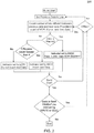
- FIG. 2 is a flowchart 200 for transmitting data with data base inversion enabled, e.g., by memory system 140 is response to a read command, according to an embodiment of the present invention.
- memory system 140 can tri-state the DQ and indicator signals, effectively holding the prior state. After issuing one or more read commands, prior to memory system 140 sending a write command or entering an idle state, memory system 140 drives the DQ data on data bus lines 132 and indicator signal on indicator line 134 low.
- this driving the DQ data on data bus lines 132 and indicator signal on indicator line 134 low can occur over two half-clock periods in order to ensure that no more than five data signals, in a group of eight data signals will switch in any transition, thus conserving power and minimizing noise.
- memory system 140 When memory system 140 is driving the signals due to a write command, the DBI behavior is similar. Between write commands, memory system 140 will hold the DQ and indicator signals. After issuing one or more write commands, prior to memory system 140 sending a read command or entering an idle state, memory system 140 will drive the DQ and indicator signals low over a two clock window.
- Flowchart 200 starts with a burst of data, setting the previous DQ byte to low. The next data DQ byte is compared to the previous DQ byte to count the number of bits that are different. Next, it is determined whether or not the data has been deemed to be masked. If the data is masked then the indicator signal is enabled, set to high. Further, the DQ signals are in a "do not care" state and the data is set such that the first half of the plurality of data bits is set low and the second half is set high. If the data is not masked, then the count of different bits is analyzed.
- the indicator signal is set to high and the nest data is inverted. If the count is less than 50% of the number of bits in the DQ byte, then the indicator signal is set to low and the next data is not inverted.
- the flowchart continues by checking if the burst has ended, if not, then the process is repeated with the choice of whether the system is utilizing DBI-ac or DBI-dc. If DBI-ac is being used then flowchart continues by counting the number of different bits between the previous data and the next data. If DBI-dc is being used the previous data is first set to low, and then the number of different bits are counted between the previous data and the next data.
- the flowchart continues by checking if back to back reads have been encountered. If so, then the flowchart continues by checking if DBI-ac or DBI-dc is used and repeats the process. If there are no back to back reads the flowchart ends.
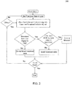
- FIG. 3 is a flowchart 300 for determining the correct data by a receiver, e.g., by memory systems 140 receiving data for a write command, according to an embodiment of the present invention.
- Flowchart 300 starts with a burst of data, setting the previous DQ byte to low.
- a data DQ byte and associated indicator signal are received and examined.
- the flowchart first determines if the indicator signal is high. If the indicator signal is low then the received data is not inverted.
- the previously received data is exclusively OR'ed with the current data to determine if the first half of the DQ byte is low and the second half of the DQ byte is set high. If it is not, then this indicates that the data is not masked, but that it should be inverted. If the data pattern does match a "masked" pattern, e.g., where the first half of the DQ byte is low and the second half of the DQ byte is high, then the data is masked.
- the data pattern indicating that the plurality of data bits is masked can be any predefined pattern, not just the example given above where the first half of the bits are low and the second half are high.
- the pattern of the plurality of data bits indicating that the bits are masked could consist of a subset of the plurality of data bits where at least one-half of the subset are set to an active state.
- data masking could be signaled where there are a certain number of bits that are set, e.g., exactly four bits are set, indicating that the plurality of data bits are masked.
- a pattern such as 0000111100001111 would indicate that the plurality of data bits are masked.
- next step in the flowchart is to determine if the burst has ended, if it has then the flowchart also concludes. If the burst has not ended then the process continues with the next DQ byte.
- FIG. 4 and FIG. 5 are flowcharts that also include the ability to generate and analyze the indicator signal in conjunction with the DQ byte to determine if the DQ data is poisoned.
- FIG. 4 is a flowchart 400 for performing DBI where data poisoning support is enabled for data being transmitted, e.g., by memory systems 140 is response to a read command, according to an embodiment of the present invention.
- memory system 140 can tri-state the DQ and indicator signals, effectively holding the prior state. After issuing one or more read commands, prior to memory system 140 sending a write command or entering an idle state, memory system 140 drives the DQ data on data bus lines 132 and indicator signal on indicator line 134 low.
- this driving the DQ data on data bus lines 132 and indicator signal on indicator line 134 low can occur over two half-clock periods in order to ensure that no more than five data signals, in a group of eight data signals will switch in any transition, thus conserving power and minimizing noise.
- memory system 140 When memory system 140 is driving the signals due to a write command, the DBI behavior is similar. Between write commands, memory system 140 will hold the DQ and indicator signals. After issuing one or more write commands, prior to memory system 140 sending a read command or entering an idle state, memory system 140 will drive the DQ and indicator signals low over a two clock window.
- Flowchart 400 starts with a burst of data, setting the previous DQ byte to low.
- the next data DQ byte is compared to the previous DQ byte to count the number of bits that are different.
- the indicator signal is enabled, set to high. Further, the DQ signals are in a "do not care" state but are patterned according to whether the DQ byte is determined to be masked or poisoned. In an embodiment, if the data is masked then the first half of the DQ byte is set low and the second half is set high (the flowchart illustrates an eight bit example where the DQ byte pattern would be 00001111). If the data is poisoned then the first half of the DQ byte is set high and the second half is set low (the flowchart illustrates an eight bit example where the DQ byte pattern would be 11110000).
- data poisoning can be signaled by any predefined pattern, not just the example given above where the first half of the bits are high and the second half are low.
- the pattern of the plurality of data bits indicating that the bits are poisoned could consist of where at least one-half of the plurality of data bits are set that are not in a subset of the plurality of data bits that indicate that the plurality of data bits is masked.
- data poisoning could be signaled where there are a certain number of bits that are set, e.g., exactly five bits are set, indicating that the plurality of data bits are poisoned.
- a pattern such as 1111000011110000 would indicate that the plurality of data bits are poisoned.
- the flowchart continues by checking if the burst has ended, if not, then the process is repeated with the choice of whether the system is utilizing DBI-ac or DBI-dc. If DBI-ac is being used then flowchart continues by counting the number of different bits between the previous data and the next data. If DBI-dc is being used the previous data is first set to low, and then the number of different bits are counted between the previous data and the next data.
- the flowchart continues by checking if back to back reads have been encountered. If so, then the flowchart continues by checking if DBI-ac or DBI-dc is used and repeats the process. If there are no back to back reads the flowchart ends.
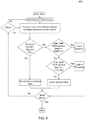
- FIG. 5 is a flowchart 500 for determining the correct data by a receiver, e.g., by memory systems 140 receiving data for a write command where data poisoning support is enabled, according to an embodiment of the present invention.
- Flowchart 500 starts with a burst of data, setting the previous DQ byte to low.
- a data DQ byte and associated indicator signal are received and examined. The flowchart first determines if the indicator signal is high. If the indicator signal is low then the received data is not inverted.
- the indicator signal is high then the previously received data is exclusively OR'ed with the current data to determine the resulting data pattern. If the first half of the DQ byte is low and the second half of the DQ byte is set high (illustrated in the flowchart of FIG. 5 with an 8 bit DQ byte where the pattern is 00001111). If the pattern matches then that indicates that the DQ byte is masked.
- the indication is that the DQ byte is poisoned.
- the current data should be inverted.
- next step in the flowchart is to determine if the burst has ended, if it has the flowchart also concludes. If the burst has not ended then the process continues with the next DQ byte.
- FIG. 6 is a flowchart of an exemplary method 600 for the generation of unified signaling.
- method 600 is described with respect to the unified signaling system of FIG. 1 using the methodology described in FIGs. 2-5 , but embodiments of the method are not limited thereto.
- Method 600 begins at step 602 with the setting a state of a single indicator signal.
- the indicator signal is set low to indicate that the next data is not to be inverted.
- the indicator signal is set high to indicate that either the next data is to be inverted, or that the plurality of data bits is masked or poisoned.
- the method continues at step 604 with the generating of a data pattern in a plurality of data bits.
- the indicator signal is set high the method also relies on the pattern of the plurality of data bits to discern whether the plurality of data bits is masked or poisoned. If the data pattern is such that the first half of the plurality of data bits is set high and the second half is set low, then the plurality of data bits is considered poisoned. If the first half of the plurality of data bits is set low and the second half is set high, then the plurality of data bits is considered masked.
- step 606 by signaling, based on the state of the single indicator signal and the pattern of the plurality of data bits, that data bus inversion has been applied to the plurality of data bits or that the plurality of data bits is poisoned.
- This step decodes the pattern of the plurality of data bits in conjunction with the state of the indicator signal to indicate the status of the plurality of data bits.
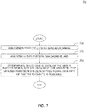
- FIG. 7 is a flowchart of an exemplary method 700 for the receiving and analyzing of unified signaling.
- method 700 is described with respect to the unified signaling system of FIG. 1 using the methodology described in FIGs. 2-5 , but embodiments of the method are not limited thereto.
- Method 700 begins at step 702 with the analyzing a state of a single indicator signal. As discussed in regards to FIG. 4 , when the indicator signal is low the next data is not inverted. When the indicator signal is set high the next data is inverted, masked or poisoned.
- the method continues at step 704 with the analyzing of a data pattern in a plurality of data bits.
- the indicator signal is set high the method also relies on the pattern of the plurality of data bits to discern whether the plurality of data bits is masked or poisoned. If the data pattern is such that the first half of the plurality of data bits is set high and the second half is set low, then the plurality of data bits is considered poisoned. If the first half of the plurality of data bits is set low and the second half is set high, then the plurality of data bits is considered masked.
- step 706 decodes the pattern of the plurality of data bits in conjunction with the state of the indicator signal to indicate the status of the plurality of data bits.
Landscapes
- Engineering & Computer Science (AREA)
- Theoretical Computer Science (AREA)
- Physics & Mathematics (AREA)
- General Engineering & Computer Science (AREA)
- General Physics & Mathematics (AREA)
- Dram (AREA)
- Bus Control (AREA)
- Information Transfer Systems (AREA)
Applications Claiming Priority (2)
| Application Number | Priority Date | Filing Date | Title |
|---|---|---|---|
| US13/325,648 US8726139B2 (en) | 2011-12-14 | 2011-12-14 | Unified data masking, data poisoning, and data bus inversion signaling |
| PCT/US2012/069541 WO2013090599A1 (en) | 2011-12-14 | 2012-12-13 | Unified data masking, data poisoning, and data bus inversion signaling |
Publications (2)
| Publication Number | Publication Date |
|---|---|
| EP2791809A1 EP2791809A1 (en) | 2014-10-22 |
| EP2791809B1 true EP2791809B1 (en) | 2017-08-02 |
Family
ID=47472088
Family Applications (1)
| Application Number | Title | Priority Date | Filing Date |
|---|---|---|---|
| EP12809487.7A Active EP2791809B1 (en) | 2011-12-14 | 2012-12-13 | Unified data masking, data poisoning, and data bus inversion signaling |
Country Status (6)
| Country | Link |
|---|---|
| US (1) | US8726139B2 (enExample) |
| EP (1) | EP2791809B1 (enExample) |
| JP (1) | JP5947398B2 (enExample) |
| KR (1) | KR101879708B1 (enExample) |
| CN (1) | CN103988192B (enExample) |
| WO (1) | WO2013090599A1 (enExample) |
Cited By (1)
| Publication number | Priority date | Publication date | Assignee | Title |
|---|---|---|---|---|
| EP4453730A4 (en) * | 2021-12-20 | 2024-11-27 | Advanced Micro Devices, Inc. | LOW POWER CACHE |
Families Citing this family (13)
| Publication number | Priority date | Publication date | Assignee | Title |
|---|---|---|---|---|
| US8677211B2 (en) * | 2010-12-23 | 2014-03-18 | International Business Machines Corporation | Data bus inversion using spare error correction bits |
| US20130117593A1 (en) * | 2011-11-07 | 2013-05-09 | Qualcomm Incorporated | Low Latency Clock Gating Scheme for Power Reduction in Bus Interconnects |
| US9529749B2 (en) | 2013-03-15 | 2016-12-27 | Qualcomm Incorporated | Data bus inversion (DBI) encoding based on the speed of operation |
| US9864536B2 (en) * | 2013-10-24 | 2018-01-09 | Qualcomm Incorporated | System and method for conserving power consumption in a memory system |
| US9383809B2 (en) | 2013-11-13 | 2016-07-05 | Qualcomm Incorporated | System and method for reducing memory I/O power via data masking |
| US9270417B2 (en) | 2013-11-21 | 2016-02-23 | Qualcomm Incorporated | Devices and methods for facilitating data inversion to limit both instantaneous current and signal transitions |
| US9817738B2 (en) * | 2015-09-04 | 2017-11-14 | Intel Corporation | Clearing poison status on read accesses to volatile memory regions allocated in non-volatile memory |
| US9922686B2 (en) * | 2016-05-19 | 2018-03-20 | Micron Technology, Inc. | Apparatuses and methods for performing intra-module databus inversion operations |
| US10754970B2 (en) * | 2017-01-27 | 2020-08-25 | International Business Machines Corporation | Data masking |
| US11237729B1 (en) | 2020-10-13 | 2022-02-01 | Sandisk Technologies Llc | Fast bus inversion for non-volatile memory |
| WO2022139849A1 (en) | 2020-12-26 | 2022-06-30 | Intel Corporation | Adaptive error correction to improve for system memory reliability, availability, and serviceability (ras) |
| KR20230046362A (ko) | 2021-09-29 | 2023-04-06 | 삼성전자주식회사 | 메모리 모듈의 동작 방법, 메모리 컨트롤러의 동작 방법, 및 메모리 시스템의 동작 방법 |
| US12050784B2 (en) * | 2022-04-27 | 2024-07-30 | Micron Technology, Inc. | Data masking for memory |
Family Cites Families (15)
| Publication number | Priority date | Publication date | Assignee | Title |
|---|---|---|---|---|
| US6898648B2 (en) * | 2002-02-21 | 2005-05-24 | Micron Technology, Inc. | Memory bus polarity indicator system and method for reducing the affects of simultaneous switching outputs (SSO) on memory bus timing |
| JP2004207942A (ja) * | 2002-12-25 | 2004-07-22 | Sony Corp | データ転送装置とデータ転送方法 |
| US8201071B2 (en) * | 2006-11-15 | 2012-06-12 | Qimonda Ag | Information transmission and reception |
| US8245087B2 (en) | 2007-03-26 | 2012-08-14 | Cray Inc. | Multi-bit memory error management |
| US7616133B2 (en) * | 2008-01-16 | 2009-11-10 | Micron Technology, Inc. | Data bus inversion apparatus, systems, and methods |
| US8363707B2 (en) * | 2008-03-21 | 2013-01-29 | Micron Technology, Inc. | Mixed-mode signaling |
| WO2009134568A2 (en) * | 2008-04-02 | 2009-11-05 | Rambus Inc. | Encoding data with minimum hamming weight variation |
| US8498344B2 (en) * | 2008-06-20 | 2013-07-30 | Rambus Inc. | Frequency responsive bus coding |
| US8271747B2 (en) | 2008-07-31 | 2012-09-18 | Rambus Inc. | Mask key selection based on defined selection criteria |
| KR20100053202A (ko) * | 2008-11-12 | 2010-05-20 | 삼성전자주식회사 | Rdbi 기능을 지원하는 반도체 메모리 장치 및 그 테스트 방법 |
| EP4535178A3 (en) | 2009-07-13 | 2025-06-18 | Rambus Inc. | Encoding data using combined data mask and data bus inversion |
| KR101688050B1 (ko) * | 2009-12-22 | 2016-12-21 | 삼성전자 주식회사 | 반도체 장치 및 반도체 장치의 리드 또는 라이트 동작 수행 방법 |
| US8260992B2 (en) * | 2010-04-12 | 2012-09-04 | Advanced Micro Devices, Inc. | Reducing simultaneous switching outputs using data bus inversion signaling |
| US8706958B2 (en) * | 2011-09-01 | 2014-04-22 | Thomas Hein | Data mask encoding in data bit inversion scheme |
| US8495437B2 (en) * | 2011-09-06 | 2013-07-23 | Samsung Electronics Co., Ltd. | Semiconductor memory device |
-
2011
- 2011-12-14 US US13/325,648 patent/US8726139B2/en active Active
-
2012
- 2012-12-13 EP EP12809487.7A patent/EP2791809B1/en active Active
- 2012-12-13 KR KR1020147016762A patent/KR101879708B1/ko active Active
- 2012-12-13 WO PCT/US2012/069541 patent/WO2013090599A1/en not_active Ceased
- 2012-12-13 CN CN201280061408.9A patent/CN103988192B/zh active Active
- 2012-12-13 JP JP2014547436A patent/JP5947398B2/ja active Active
Non-Patent Citations (1)
| Title |
|---|
| None * |
Cited By (1)
| Publication number | Priority date | Publication date | Assignee | Title |
|---|---|---|---|---|
| EP4453730A4 (en) * | 2021-12-20 | 2024-11-27 | Advanced Micro Devices, Inc. | LOW POWER CACHE |
Also Published As
| Publication number | Publication date |
|---|---|
| CN103988192B (zh) | 2018-02-09 |
| CN103988192A (zh) | 2014-08-13 |
| US20130159818A1 (en) | 2013-06-20 |
| JP5947398B2 (ja) | 2016-07-06 |
| JP2015506039A (ja) | 2015-02-26 |
| KR101879708B1 (ko) | 2018-07-18 |
| KR20140102703A (ko) | 2014-08-22 |
| WO2013090599A1 (en) | 2013-06-20 |
| EP2791809A1 (en) | 2014-10-22 |
| US8726139B2 (en) | 2014-05-13 |
Similar Documents
| Publication | Publication Date | Title |
|---|---|---|
| EP2791809B1 (en) | Unified data masking, data poisoning, and data bus inversion signaling | |
| EP3377974B1 (en) | Separate link and array error correction in a memory system | |
| CN108351820B (zh) | 在跨存储器链路传送纠正数据时保护ecc位置 | |
| US10579462B2 (en) | Method and apparatus for using an error signal to indicate a write request error and write request acceptance | |
| US9978430B2 (en) | Memory devices providing a refresh request and memory controllers responsive to a refresh request | |
| JP3177207B2 (ja) | リフレッシュ間隔制御装置及び方法、並びにコンピュータ | |
| US8493797B2 (en) | Memory system and method having volatile and non-volatile memory devices at same hierarchical level | |
| US10061645B2 (en) | Memory array and link error correction in a low power memory sub-system | |
| US9158616B2 (en) | Method and system for error management in a memory device | |
| KR20190019209A (ko) | Ddr 메모리 에러 복구 | |
| US8738993B2 (en) | Memory device on the fly CRC mode | |
| CN114078503B (zh) | 基于存储器装置中的局部命令解码的突发时钟控制 | |
| KR20190098394A (ko) | 메모리 컨트롤러 및 그 동작 방법 | |
| US11610624B2 (en) | Memory device skipping refresh operation and operation method thereof | |
| US20250130877A1 (en) | Handling Faulty Usage-Based-Disturbance Data | |
| US20120191898A1 (en) | Ddr flash implementation with direct register access to legacy flash functions | |
| US20150071022A1 (en) | Apparatuses and methods for providing active and inactive clock signals to a command path circuit | |
| US20250190379A1 (en) | Variable burst length for a memory device | |
| US12585542B2 (en) | Locked raid with compression for memory interconnect applications having a shared cache line | |
| US20250383947A1 (en) | Per row activation counting error handling | |
| TW202223903A (zh) | 適應性內部記憶體錯誤刷洗及錯誤處置 |
Legal Events
| Date | Code | Title | Description |
|---|---|---|---|
| PUAI | Public reference made under article 153(3) epc to a published international application that has entered the european phase |
Free format text: ORIGINAL CODE: 0009012 |
|
| 17P | Request for examination filed |
Effective date: 20140630 |
|
| AK | Designated contracting states |
Kind code of ref document: A1 Designated state(s): AL AT BE BG CH CY CZ DE DK EE ES FI FR GB GR HR HU IE IS IT LI LT LU LV MC MK MT NL NO PL PT RO RS SE SI SK SM TR |
|
| DAX | Request for extension of the european patent (deleted) | ||
| 17Q | First examination report despatched |
Effective date: 20160624 |
|
| GRAP | Despatch of communication of intention to grant a patent |
Free format text: ORIGINAL CODE: EPIDOSNIGR1 |
|
| INTG | Intention to grant announced |
Effective date: 20170227 |
|
| GRAS | Grant fee paid |
Free format text: ORIGINAL CODE: EPIDOSNIGR3 |
|
| GRAA | (expected) grant |
Free format text: ORIGINAL CODE: 0009210 |
|
| AK | Designated contracting states |
Kind code of ref document: B1 Designated state(s): AL AT BE BG CH CY CZ DE DK EE ES FI FR GB GR HR HU IE IS IT LI LT LU LV MC MK MT NL NO PL PT RO RS SE SI SK SM TR |
|
| REG | Reference to a national code |
Ref country code: CH Ref legal event code: EP Ref country code: AT Ref legal event code: REF Ref document number: 915200 Country of ref document: AT Kind code of ref document: T Effective date: 20170815 |
|
| REG | Reference to a national code |
Ref country code: IE Ref legal event code: FG4D |
|
| REG | Reference to a national code |
Ref country code: DE Ref legal event code: R096 Ref document number: 602012035428 Country of ref document: DE |
|
| REG | Reference to a national code |
Ref country code: NL Ref legal event code: MP Effective date: 20170802 |
|
| REG | Reference to a national code |
Ref country code: AT Ref legal event code: MK05 Ref document number: 915200 Country of ref document: AT Kind code of ref document: T Effective date: 20170802 |
|
| REG | Reference to a national code |
Ref country code: LT Ref legal event code: MG4D |
|
| PG25 | Lapsed in a contracting state [announced via postgrant information from national office to epo] |
Ref country code: HR Free format text: LAPSE BECAUSE OF FAILURE TO SUBMIT A TRANSLATION OF THE DESCRIPTION OR TO PAY THE FEE WITHIN THE PRESCRIBED TIME-LIMIT Effective date: 20170802 Ref country code: FI Free format text: LAPSE BECAUSE OF FAILURE TO SUBMIT A TRANSLATION OF THE DESCRIPTION OR TO PAY THE FEE WITHIN THE PRESCRIBED TIME-LIMIT Effective date: 20170802 Ref country code: LT Free format text: LAPSE BECAUSE OF FAILURE TO SUBMIT A TRANSLATION OF THE DESCRIPTION OR TO PAY THE FEE WITHIN THE PRESCRIBED TIME-LIMIT Effective date: 20170802 Ref country code: NO Free format text: LAPSE BECAUSE OF FAILURE TO SUBMIT A TRANSLATION OF THE DESCRIPTION OR TO PAY THE FEE WITHIN THE PRESCRIBED TIME-LIMIT Effective date: 20171102 Ref country code: SE Free format text: LAPSE BECAUSE OF FAILURE TO SUBMIT A TRANSLATION OF THE DESCRIPTION OR TO PAY THE FEE WITHIN THE PRESCRIBED TIME-LIMIT Effective date: 20170802 Ref country code: AT Free format text: LAPSE BECAUSE OF FAILURE TO SUBMIT A TRANSLATION OF THE DESCRIPTION OR TO PAY THE FEE WITHIN THE PRESCRIBED TIME-LIMIT Effective date: 20170802 Ref country code: NL Free format text: LAPSE BECAUSE OF FAILURE TO SUBMIT A TRANSLATION OF THE DESCRIPTION OR TO PAY THE FEE WITHIN THE PRESCRIBED TIME-LIMIT Effective date: 20170802 |
|
| PG25 | Lapsed in a contracting state [announced via postgrant information from national office to epo] |
Ref country code: RS Free format text: LAPSE BECAUSE OF FAILURE TO SUBMIT A TRANSLATION OF THE DESCRIPTION OR TO PAY THE FEE WITHIN THE PRESCRIBED TIME-LIMIT Effective date: 20170802 Ref country code: IS Free format text: LAPSE BECAUSE OF FAILURE TO SUBMIT A TRANSLATION OF THE DESCRIPTION OR TO PAY THE FEE WITHIN THE PRESCRIBED TIME-LIMIT Effective date: 20171202 Ref country code: ES Free format text: LAPSE BECAUSE OF FAILURE TO SUBMIT A TRANSLATION OF THE DESCRIPTION OR TO PAY THE FEE WITHIN THE PRESCRIBED TIME-LIMIT Effective date: 20170802 Ref country code: PL Free format text: LAPSE BECAUSE OF FAILURE TO SUBMIT A TRANSLATION OF THE DESCRIPTION OR TO PAY THE FEE WITHIN THE PRESCRIBED TIME-LIMIT Effective date: 20170802 Ref country code: GR Free format text: LAPSE BECAUSE OF FAILURE TO SUBMIT A TRANSLATION OF THE DESCRIPTION OR TO PAY THE FEE WITHIN THE PRESCRIBED TIME-LIMIT Effective date: 20171103 Ref country code: LV Free format text: LAPSE BECAUSE OF FAILURE TO SUBMIT A TRANSLATION OF THE DESCRIPTION OR TO PAY THE FEE WITHIN THE PRESCRIBED TIME-LIMIT Effective date: 20170802 Ref country code: BG Free format text: LAPSE BECAUSE OF FAILURE TO SUBMIT A TRANSLATION OF THE DESCRIPTION OR TO PAY THE FEE WITHIN THE PRESCRIBED TIME-LIMIT Effective date: 20171102 |
|
| RAP2 | Party data changed (patent owner data changed or rights of a patent transferred) |
Owner name: ADVANCED MICRO DEVICES, INC. |
|
| PG25 | Lapsed in a contracting state [announced via postgrant information from national office to epo] |
Ref country code: RO Free format text: LAPSE BECAUSE OF FAILURE TO SUBMIT A TRANSLATION OF THE DESCRIPTION OR TO PAY THE FEE WITHIN THE PRESCRIBED TIME-LIMIT Effective date: 20170802 Ref country code: DK Free format text: LAPSE BECAUSE OF FAILURE TO SUBMIT A TRANSLATION OF THE DESCRIPTION OR TO PAY THE FEE WITHIN THE PRESCRIBED TIME-LIMIT Effective date: 20170802 Ref country code: CZ Free format text: LAPSE BECAUSE OF FAILURE TO SUBMIT A TRANSLATION OF THE DESCRIPTION OR TO PAY THE FEE WITHIN THE PRESCRIBED TIME-LIMIT Effective date: 20170802 |
|
| RAP2 | Party data changed (patent owner data changed or rights of a patent transferred) |
Owner name: ADVANCED MICRO DEVICES, INC. |
|
| REG | Reference to a national code |
Ref country code: DE Ref legal event code: R097 Ref document number: 602012035428 Country of ref document: DE |
|
| PG25 | Lapsed in a contracting state [announced via postgrant information from national office to epo] |
Ref country code: EE Free format text: LAPSE BECAUSE OF FAILURE TO SUBMIT A TRANSLATION OF THE DESCRIPTION OR TO PAY THE FEE WITHIN THE PRESCRIBED TIME-LIMIT Effective date: 20170802 Ref country code: IT Free format text: LAPSE BECAUSE OF FAILURE TO SUBMIT A TRANSLATION OF THE DESCRIPTION OR TO PAY THE FEE WITHIN THE PRESCRIBED TIME-LIMIT Effective date: 20170802 Ref country code: SK Free format text: LAPSE BECAUSE OF FAILURE TO SUBMIT A TRANSLATION OF THE DESCRIPTION OR TO PAY THE FEE WITHIN THE PRESCRIBED TIME-LIMIT Effective date: 20170802 Ref country code: SM Free format text: LAPSE BECAUSE OF FAILURE TO SUBMIT A TRANSLATION OF THE DESCRIPTION OR TO PAY THE FEE WITHIN THE PRESCRIBED TIME-LIMIT Effective date: 20170802 |
|
| PLBE | No opposition filed within time limit |
Free format text: ORIGINAL CODE: 0009261 |
|
| STAA | Information on the status of an ep patent application or granted ep patent |
Free format text: STATUS: NO OPPOSITION FILED WITHIN TIME LIMIT |
|
| 26N | No opposition filed |
Effective date: 20180503 |
|
| REG | Reference to a national code |
Ref country code: CH Ref legal event code: PL |
|
| PG25 | Lapsed in a contracting state [announced via postgrant information from national office to epo] |
Ref country code: SI Free format text: LAPSE BECAUSE OF FAILURE TO SUBMIT A TRANSLATION OF THE DESCRIPTION OR TO PAY THE FEE WITHIN THE PRESCRIBED TIME-LIMIT Effective date: 20170802 |
|
| REG | Reference to a national code |
Ref country code: IE Ref legal event code: MM4A |
|
| PG25 | Lapsed in a contracting state [announced via postgrant information from national office to epo] |
Ref country code: MT Free format text: LAPSE BECAUSE OF NON-PAYMENT OF DUE FEES Effective date: 20171213 Ref country code: LU Free format text: LAPSE BECAUSE OF NON-PAYMENT OF DUE FEES Effective date: 20171213 |
|
| REG | Reference to a national code |
Ref country code: FR Ref legal event code: ST Effective date: 20180831 |
|
| REG | Reference to a national code |
Ref country code: BE Ref legal event code: MM Effective date: 20171231 |
|
| PG25 | Lapsed in a contracting state [announced via postgrant information from national office to epo] |
Ref country code: FR Free format text: LAPSE BECAUSE OF NON-PAYMENT OF DUE FEES Effective date: 20180102 Ref country code: IE Free format text: LAPSE BECAUSE OF NON-PAYMENT OF DUE FEES Effective date: 20171213 |
|
| PG25 | Lapsed in a contracting state [announced via postgrant information from national office to epo] |
Ref country code: BE Free format text: LAPSE BECAUSE OF NON-PAYMENT OF DUE FEES Effective date: 20171231 Ref country code: CH Free format text: LAPSE BECAUSE OF NON-PAYMENT OF DUE FEES Effective date: 20171231 Ref country code: LI Free format text: LAPSE BECAUSE OF NON-PAYMENT OF DUE FEES Effective date: 20171231 |
|
| PG25 | Lapsed in a contracting state [announced via postgrant information from national office to epo] |
Ref country code: MC Free format text: LAPSE BECAUSE OF FAILURE TO SUBMIT A TRANSLATION OF THE DESCRIPTION OR TO PAY THE FEE WITHIN THE PRESCRIBED TIME-LIMIT Effective date: 20170802 Ref country code: HU Free format text: LAPSE BECAUSE OF FAILURE TO SUBMIT A TRANSLATION OF THE DESCRIPTION OR TO PAY THE FEE WITHIN THE PRESCRIBED TIME-LIMIT; INVALID AB INITIO Effective date: 20121213 |
|
| PG25 | Lapsed in a contracting state [announced via postgrant information from national office to epo] |
Ref country code: CY Free format text: LAPSE BECAUSE OF FAILURE TO SUBMIT A TRANSLATION OF THE DESCRIPTION OR TO PAY THE FEE WITHIN THE PRESCRIBED TIME-LIMIT Effective date: 20170802 |
|
| PG25 | Lapsed in a contracting state [announced via postgrant information from national office to epo] |
Ref country code: MK Free format text: LAPSE BECAUSE OF FAILURE TO SUBMIT A TRANSLATION OF THE DESCRIPTION OR TO PAY THE FEE WITHIN THE PRESCRIBED TIME-LIMIT Effective date: 20170802 |
|
| PG25 | Lapsed in a contracting state [announced via postgrant information from national office to epo] |
Ref country code: TR Free format text: LAPSE BECAUSE OF FAILURE TO SUBMIT A TRANSLATION OF THE DESCRIPTION OR TO PAY THE FEE WITHIN THE PRESCRIBED TIME-LIMIT Effective date: 20170802 |
|
| PG25 | Lapsed in a contracting state [announced via postgrant information from national office to epo] |
Ref country code: PT Free format text: LAPSE BECAUSE OF FAILURE TO SUBMIT A TRANSLATION OF THE DESCRIPTION OR TO PAY THE FEE WITHIN THE PRESCRIBED TIME-LIMIT Effective date: 20170802 |
|
| PG25 | Lapsed in a contracting state [announced via postgrant information from national office to epo] |
Ref country code: AL Free format text: LAPSE BECAUSE OF FAILURE TO SUBMIT A TRANSLATION OF THE DESCRIPTION OR TO PAY THE FEE WITHIN THE PRESCRIBED TIME-LIMIT Effective date: 20170802 |
|
| P01 | Opt-out of the competence of the unified patent court (upc) registered |
Effective date: 20230530 |
|
| PGFP | Annual fee paid to national office [announced via postgrant information from national office to epo] |
Ref country code: DE Payment date: 20251113 Year of fee payment: 14 |
|
| PGFP | Annual fee paid to national office [announced via postgrant information from national office to epo] |
Ref country code: GB Payment date: 20251203 Year of fee payment: 14 |