EP2788604B1 - Antriebsstrang - Google Patents
Antriebsstrang Download PDFInfo
- Publication number
- EP2788604B1 EP2788604B1 EP12815617.1A EP12815617A EP2788604B1 EP 2788604 B1 EP2788604 B1 EP 2788604B1 EP 12815617 A EP12815617 A EP 12815617A EP 2788604 B1 EP2788604 B1 EP 2788604B1
- Authority
- EP
- European Patent Office
- Prior art keywords
- torsional vibration
- rotary vibration
- damper
- vibration damper
- centrifugal pendulum
- Prior art date
- Legal status (The legal status is an assumption and is not a legal conclusion. Google has not performed a legal analysis and makes no representation as to the accuracy of the status listed.)
- Revoked
Links
- 238000013016 damping Methods 0.000 claims description 37
- 238000002485 combustion reaction Methods 0.000 claims description 21
- 238000010586 diagram Methods 0.000 description 14
- 230000005540 biological transmission Effects 0.000 description 10
- 230000000694 effects Effects 0.000 description 2
- 239000006096 absorbing agent Substances 0.000 description 1
- 230000015572 biosynthetic process Effects 0.000 description 1
- 230000006835 compression Effects 0.000 description 1
- 238000007906 compression Methods 0.000 description 1
- 230000009849 deactivation Effects 0.000 description 1
- 230000001419 dependent effect Effects 0.000 description 1
- 230000008029 eradication Effects 0.000 description 1
- 238000002955 isolation Methods 0.000 description 1
- 230000010355 oscillation Effects 0.000 description 1
Images
Classifications
-
- F—MECHANICAL ENGINEERING; LIGHTING; HEATING; WEAPONS; BLASTING
- F16—ENGINEERING ELEMENTS AND UNITS; GENERAL MEASURES FOR PRODUCING AND MAINTAINING EFFECTIVE FUNCTIONING OF MACHINES OR INSTALLATIONS; THERMAL INSULATION IN GENERAL
- F16F—SPRINGS; SHOCK-ABSORBERS; MEANS FOR DAMPING VIBRATION
- F16F15/00—Suppression of vibrations in systems; Means or arrangements for avoiding or reducing out-of-balance forces, e.g. due to motion
- F16F15/10—Suppression of vibrations in rotating systems by making use of members moving with the system
- F16F15/14—Suppression of vibrations in rotating systems by making use of members moving with the system using masses freely rotating with the system, i.e. uninvolved in transmitting driveline torque, e.g. rotative dynamic dampers
-
- F—MECHANICAL ENGINEERING; LIGHTING; HEATING; WEAPONS; BLASTING
- F16—ENGINEERING ELEMENTS AND UNITS; GENERAL MEASURES FOR PRODUCING AND MAINTAINING EFFECTIVE FUNCTIONING OF MACHINES OR INSTALLATIONS; THERMAL INSULATION IN GENERAL
- F16F—SPRINGS; SHOCK-ABSORBERS; MEANS FOR DAMPING VIBRATION
- F16F15/00—Suppression of vibrations in systems; Means or arrangements for avoiding or reducing out-of-balance forces, e.g. due to motion
- F16F15/10—Suppression of vibrations in rotating systems by making use of members moving with the system
- F16F15/12—Suppression of vibrations in rotating systems by making use of members moving with the system using elastic members or friction-damping members, e.g. between a rotating shaft and a gyratory mass mounted thereon
- F16F15/131—Suppression of vibrations in rotating systems by making use of members moving with the system using elastic members or friction-damping members, e.g. between a rotating shaft and a gyratory mass mounted thereon the rotating system comprising two or more gyratory masses
-
- F—MECHANICAL ENGINEERING; LIGHTING; HEATING; WEAPONS; BLASTING
- F16—ENGINEERING ELEMENTS AND UNITS; GENERAL MEASURES FOR PRODUCING AND MAINTAINING EFFECTIVE FUNCTIONING OF MACHINES OR INSTALLATIONS; THERMAL INSULATION IN GENERAL
- F16F—SPRINGS; SHOCK-ABSORBERS; MEANS FOR DAMPING VIBRATION
- F16F15/00—Suppression of vibrations in systems; Means or arrangements for avoiding or reducing out-of-balance forces, e.g. due to motion
- F16F15/10—Suppression of vibrations in rotating systems by making use of members moving with the system
- F16F15/12—Suppression of vibrations in rotating systems by making use of members moving with the system using elastic members or friction-damping members, e.g. between a rotating shaft and a gyratory mass mounted thereon
- F16F15/129—Suppression of vibrations in rotating systems by making use of members moving with the system using elastic members or friction-damping members, e.g. between a rotating shaft and a gyratory mass mounted thereon characterised by friction-damping means
-
- F—MECHANICAL ENGINEERING; LIGHTING; HEATING; WEAPONS; BLASTING
- F16—ENGINEERING ELEMENTS AND UNITS; GENERAL MEASURES FOR PRODUCING AND MAINTAINING EFFECTIVE FUNCTIONING OF MACHINES OR INSTALLATIONS; THERMAL INSULATION IN GENERAL
- F16F—SPRINGS; SHOCK-ABSORBERS; MEANS FOR DAMPING VIBRATION
- F16F15/00—Suppression of vibrations in systems; Means or arrangements for avoiding or reducing out-of-balance forces, e.g. due to motion
- F16F15/10—Suppression of vibrations in rotating systems by making use of members moving with the system
- F16F15/14—Suppression of vibrations in rotating systems by making use of members moving with the system using masses freely rotating with the system, i.e. uninvolved in transmitting driveline torque, e.g. rotative dynamic dampers
- F16F15/1407—Suppression of vibrations in rotating systems by making use of members moving with the system using masses freely rotating with the system, i.e. uninvolved in transmitting driveline torque, e.g. rotative dynamic dampers the rotation being limited with respect to the driving means
-
- F—MECHANICAL ENGINEERING; LIGHTING; HEATING; WEAPONS; BLASTING
- F02—COMBUSTION ENGINES; HOT-GAS OR COMBUSTION-PRODUCT ENGINE PLANTS
- F02D—CONTROLLING COMBUSTION ENGINES
- F02D13/00—Controlling the engine output power by varying inlet or exhaust valve operating characteristics, e.g. timing
- F02D13/02—Controlling the engine output power by varying inlet or exhaust valve operating characteristics, e.g. timing during engine operation
- F02D13/06—Cutting-out cylinders
-
- F—MECHANICAL ENGINEERING; LIGHTING; HEATING; WEAPONS; BLASTING
- F16—ENGINEERING ELEMENTS AND UNITS; GENERAL MEASURES FOR PRODUCING AND MAINTAINING EFFECTIVE FUNCTIONING OF MACHINES OR INSTALLATIONS; THERMAL INSULATION IN GENERAL
- F16F—SPRINGS; SHOCK-ABSORBERS; MEANS FOR DAMPING VIBRATION
- F16F15/00—Suppression of vibrations in systems; Means or arrangements for avoiding or reducing out-of-balance forces, e.g. due to motion
- F16F15/10—Suppression of vibrations in rotating systems by making use of members moving with the system
- F16F15/14—Suppression of vibrations in rotating systems by making use of members moving with the system using masses freely rotating with the system, i.e. uninvolved in transmitting driveline torque, e.g. rotative dynamic dampers
- F16F15/1407—Suppression of vibrations in rotating systems by making use of members moving with the system using masses freely rotating with the system, i.e. uninvolved in transmitting driveline torque, e.g. rotative dynamic dampers the rotation being limited with respect to the driving means
- F16F15/145—Masses mounted with play with respect to driving means thus enabling free movement over a limited range
-
- Y—GENERAL TAGGING OF NEW TECHNOLOGICAL DEVELOPMENTS; GENERAL TAGGING OF CROSS-SECTIONAL TECHNOLOGIES SPANNING OVER SEVERAL SECTIONS OF THE IPC; TECHNICAL SUBJECTS COVERED BY FORMER USPC CROSS-REFERENCE ART COLLECTIONS [XRACs] AND DIGESTS
- Y10—TECHNICAL SUBJECTS COVERED BY FORMER USPC
- Y10T—TECHNICAL SUBJECTS COVERED BY FORMER US CLASSIFICATION
- Y10T74/00—Machine element or mechanism
- Y10T74/21—Elements
- Y10T74/2121—Flywheel, motion smoothing-type
- Y10T74/2128—Damping using swinging masses, e.g., pendulum type, etc.
Definitions
- the invention relates to a drive train with an internal combustion engine with a predetermined number of cylinders with a first operating state in which all cylinders are operated, and a second operating state in which a part of the cylinder is turned off, and with a torsional vibration damping system with at least one torsional vibration damper and at least a centrifugal pendulum.
- Generic drive trains are preferably used in motor vehicles and include an internal combustion engine, a transmission and an output for driving the motor vehicle.
- torsional vibration systems which contain, for example, one or more torsional vibration dampers. These are preferably housed on the crankshaft or a transmission input shaft of the transmission and may be split flywheels, torsional vibration dampers in clutch disks of a provided between the crankshaft and the transmission input shaft friction clutch and the like and are for example from the documents DE 37 03 123 A1 and DE 34 42 705 A1 known.
- torsional vibration damping centrifugal pendulum example of the DE 10 2010 005 599 A1 become known, which form a speed-adaptive torsional vibration damper by means of a pendulum flange limited pivotable pendulum masses against a recorded with the crankshaft or transmission input shaft pendulum.
- combinations of centrifugal pendulums with the designated torsional vibration dampers for example, from WO 2011/110153 A1 .
- DE 10 2010 018 941 A1 and DE 10 2010 022 252 A1 known.
- the torsional vibration damping system is tuned to the torsional vibration behavior of the internal combustion engine, for example, on the vibration order. For example, four-cycle engines with four cylinders have vibration orders equal to two and four-cycle engines with two cylinders have vibration orders equal to one.
- the document DE 10 2011 012606 A1 is considered as the closest prior art and discloses a powertrain with an internal combustion engine and with a torsional vibration damping system with at least one torsional vibration damper and at least one centrifugal pendulum.
- the object of the invention is therefore to propose a drive train, which achieves an improved torsional vibration behavior via both operating states of the internal combustion engine by means of an adapted torsional vibration system.
- a drive train with an internal combustion engine having a predetermined number of cylinders with a first operating state, in which all cylinders are operated, and a second operating state, in which a part of the cylinders is switched off, and with a torsional vibration damping system with at least one torsional vibration damper and solved at least one centrifugal pendulum, wherein a centrifugal pendulum and optionally a torsional vibration damper are tuned to a torsional vibration behavior of an operating condition and a torsional vibration damper and optionally a second centrifugal pendulum to the torsional vibration behavior of the other operating state.
- the torsional vibration behavior of the two operating states of the internal combustion engine can be selectively improved relative to each operating state.
- one or more components can be assigned to each operating state.
- One or more torsional vibration dampers can be used as a split flywheel with an effectively assigned in the circumferential direction between a primary, the crankshaft and a secondary, a transmission input shaft of a transmission effectively arranged spring means with at least one damper stage, as a torsional vibration damper in a clutch disc with at least one damper stage, one in the drive train be formed between the internal combustion engine and a transmission arranged friction clutch or the like. If a plurality of damper stages are provided in a torsional vibration damper, a damper stage may be assigned to the one and the other damper stage the other operating condition and be tuned to improve their torsional vibration behavior.
- the stiffness of the damper stages in the circumferential direction and rotation angle between input and output parts of the torsional vibration damper are adjusted accordingly.
- the damper stages lower rigidity are preferably bridged at higher torques, so that they are spared.
- the spring means may be formed of bow springs and / or coil springs, wherein bow springs and otherwise preferably helical compression springs are preferably provided in a damper stage of a split flywheel.
- centrifugal pendulums can be arranged at different locations of the drive train. Also, it may be advantageous if a single centrifugal pendulum is tuned to two different vibration orders by, for example, pendulum masses are provided with different vibration behavior by these have adapted to each a vibration order masses and / or swing angle. In each case a centrifugal pendulum can be arranged on the primary or secondary flywheel of a torsional vibration damper and / or on a torsional vibration damper in a clutch disc or on a disposed in the drive train between the crankshaft and the transmission input shaft friction clutch.
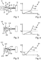
- FIG. 1 schematically shows the powertrain 10 with the operable in two operating states optionally with four or two cylinders 11 and the torsional vibration damping system 12 and the torsionally elastic means of torsional elasticity coupled 13, gearbox and vehicle body only hinting unit 14.
- the torsional vibration damping system 12 is from the split as a flywheel 16th formed with the primary flywheel 17 and the secondary flywheel 18 first torsional vibration damper 15, the downstream, integrated in a clutch disc of a friction clutch second torsional vibration damper 19 and the primary side arranged centrifugal pendulum 20.
- the first, two-stage torsional vibration damper 15 is associated with a spring device with the spring constants c1, c2.
- the centrifugal pendulum 20 is tuned to the order of vibration one. Furthermore, the second damper stage is tuned with the spring constant c2 higher rigidity on the operation in the first operating state.
- the second torsional vibration damper 19 can be assigned to an operating state either selectively or across.
- FIG. 2 shows the diagram 21 in which in the torque curve 22, the torque of the first torsional vibration damper 15 of FIG. 1 is plotted against the angle of rotation ⁇ of the flywheels 17, 18. Since in the second operating state of the internal combustion engine 11 whose maximum switch-off torque M Z is correspondingly reduced with deactivated cylinders, a sufficient damping effect can be achieved by means of the damper stage with the spring constant c1, while with the cylinders connected in the first operating state at lying over the switch-off torque M Z moments the second damper stage with the spring constant c2 and the centrifugal pendulum 20, the effect of which is not visible here are effective as speed-adaptive absorber.
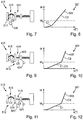
- FIG. 3 shows in contrast to the drive train 10 of FIG. 1 the drive train 110, in which the torsional vibration damping system 112 with the first torsional vibration damper 115 and the second torsional vibration damper 119, the centrifugal pendulum 120 arranged on the primary side of the flywheel 117 has.
- the centrifugal pendulum 120 is tuned to the vibration order of the internal combustion engine during operation of all cylinders, that is, to the first operating state, in the case of a four-cylinder engine according to the 4-stroke principle on the vibration order two. Since the primary-side flywheel 117 is increased by the centrifugal pendulum 120, the second operating state also benefits through more effective eradication, although the centrifugal pendulum 120 is not tuned to its oscillation order.
- FIG. 4 shows that from the torsional vibration damper 115 of FIG. 3 resulting diagram 121 with the torque characteristic 122 with the two damper stages according to diagram 21 of FIG. 2 assignable spring constants c1, c2.
- FIG. 5 shows the drive train 10 of the FIG. 1 Similar powertrain 210 with the torsional vibration damping system 212 with the two torsional vibration dampers 215, 219 and the secondary side of the secondary flywheel 218 arranged centrifugal pendulum 220.
- the second damper stage of the first torsional vibration damper 15 with the spring constant c2 in contrast to the second damper stage of the first torsional vibration damper 15 with the spring constant c2, the second damper stage of the first torsional vibration damper 215 with the spring constant c2 over a wide torque range in two operating states of the internal combustion engine effectively.
- the first damper stage may damp idle vibrations or may be omitted for simplicity of the first torsional vibration damper 215.
- FIG. 7 the drive trains 110, 210 of the FIGS. 3 and 5 similar powertrain 310 with the corresponding torsional vibration damping system 312, wherein the centrifugal pendulum 320 is disposed on the primary flywheel 317 of the first torsional vibration damper 315.
- the formation of the damper stages with the spring constants c1, c2 of the first torsional vibration damper 315 is similar to the torsional vibration damper 215 of FIG. 5 ,
- FIG. 9 shows the powertrain 410 with the torsional vibration damping system 412 with the two torsional vibration dampers 415, 419 and the centrifugal pendulum 424, which is arranged in contrast to the previously illustrated drive trains on the second torsional vibration damper 419, for example, a torsional vibration damper a clutch disc.
- the torsional vibration damping system improves the torsional vibrations of the drive train 410 by the centrifugal pendulum 424 arranged on the second torsional vibration damper 419, that is to the vibration order two of a four-cylinder engine according to the 4-stroke principle and a second damper stage of high rigidity with the spring constant c2 on the torsional vibration behavior of the first operating state and on the torsional vibration behavior of the second operating state, a first damper stage of low rigidity with the spring constant c1 of the first torsional vibration damper 415 and additionally or alternatively a spring means 423 of the second torsional vibration damper 419 are tuned.
- FIG. 10 shows the diagram 421 with the torque characteristic 422 of the torsional vibration damping system 412 of FIG. 9 ,
- the first damper stage of the first torsional vibration damper 415 with the spring constant c1 and additionally or alternatively in a single-stage torsional vibration damper 415, the spring means 423 with the spring constant c3 of the second torsional vibration damper 419 is provided.
- the second damper stage provided with the spring constant c2 for damping the torsional vibrations.
- FIG. 11 shows the driveline 410 similar powertrain 510 with the torsional vibration damping system 512.
- a centrifugal pendulum 520, 524 is arranged on each of the torsional vibration damper 515, 519.
- the torsional vibration behavior of the first operating state for example with torsional vibrations of the vibration order two
- the torsional vibration behavior of the second operating state for example with torsional vibrations of the vibration order one, on the second torsional vibration damper 519 arranged centrifugal pendulum tuned.
- the centrifugal pendulum 520 arranged on the secondary flywheel 518 of the first torsional vibration damper 515 and the torsional vibration behavior of the first operating state may be tuned to the torsional vibration behavior of the second operating state, the centrifugal pendulum 524 arranged on the second torsional vibration damper 519.
- a first spring device with low rigidity up to the maximum switch-off moment M Z and a second spring device with high rigidity are provided for larger moments of the internal combustion engine.
- both torsional vibration dampers 515, 519 can be provided in one stage and a respective torsional vibration damper 515, 519 can be assigned to an operating state and thus to a centrifugal pendulum 520, 524.
- the torsional vibration damper 515 is provided with a spring means of low rigidity, for example in the form of bow springs with the spring constant c1, while provided in a clutch disc torsional vibration damper 519 has a spring means with higher rigidity with the spring constant c3.
- a clutch disk without torsional vibration damper and with only one centrifugal pendulum 524 may be formed, while the torsional vibration damper 515 is formed with different stiffness damper stages corresponding to the spring constants c1, c3 of the diagram 521.
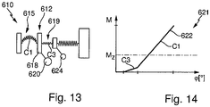
- FIG. 13 shows the powertrain 510 of the FIG. 11 similar powertrain 610 with the torsional vibration damping system 612.
- the two centrifugal pendulum 620, 624 are tuned to a respective vibration level of an operating condition.
- the centrifugal pendulum 624 arranged on the second torsional vibration damper 619 and on the torsional vibration behavior is dependent on the torsional vibration behavior of the first operating state of the second operating state a arranged on a secondary flywheel 618 of the first torsional vibration damper 615 centrifugal pendulum 620 tuned.
- the damper stages of the torsional vibration damper 615, 619 are - as from the diagram 621 with the torque curve 622 of FIG.
- the damper stage with the spring constant c1 is associated with the first torsional vibration damper 615, while the soft damper stage with the spring constant c3 is associated with the torsional vibration damper 619.
- the assignment of the damper stages to the torsional vibration dampers 615, 619 may be reversed, or only a two-stage torsional vibration damper 615 having damper stages with the spring constants c1, c3 may be provided, with the corresponding centrifugal pendulum 620 attached to the clutch disc without torsional vibration damper.
Landscapes
- Engineering & Computer Science (AREA)
- General Engineering & Computer Science (AREA)
- Physics & Mathematics (AREA)
- Acoustics & Sound (AREA)
- Aviation & Aerospace Engineering (AREA)
- Mechanical Engineering (AREA)
- Mechanical Operated Clutches (AREA)
Description
- Die Erfindung betrifft einen Antriebsstrang mit einer Brennkraftmaschine mit einer vorgegebenen Anzahl von Zylindern mit einem ersten Betriebszustand, in dem alle Zylinder betrieben werden, und einem zweiten Betriebszustand, in dem ein Teil der Zylinder abgeschaltet ist, und mit einem Drehschwingungsdämpfungssystem mit zumindest einem Drehschwingungsdämpfer und zumindest einem Fliehkraftpendel.
- Gattungsgemäße Antriebsstränge werden bevorzugt in Kraftfahrzeugen eingesetzt und enthalten eine Brennkraftmaschine, ein Getriebe und einen Abtrieb zum Antrieb des Kraftfahrzeugs. Zur Isolation und Dämpfung von Drehschwingungen der Brennkraftmaschine sind Drehschwingungssysteme bekannt, die beispielsweise einen oder mehrere Drehschwingungsdämpfer enthalten. Diese sind bevorzugt auf der Kurbelwelle oder einer Getriebeeingangswelle des Getriebes aufgenommen und können geteilte Schwungräder, Torsionsschwingungsdämpfer in Kupplungsscheiben einer zwischen der Kurbelwelle und der Getriebeeingangswelle vorgesehenen Reibungskupplung und dergleichen sein und sind beispielsweise aus den Dokumenten
DE 37 03 123 A1 undDE 34 42 705 A1 bekannt. Weiterhin sind zur Drehschwingungstilgung Fliehkraftpendel beispielsweise aus derDE 10 2010 005 599 A1 bekannt geworden, welche mittels gegenüber einem mit der Kurbelwelle oder Getriebeeingangswelle aufgenommenen Pendelflansch begrenzt verschwenkbarer Pendelmassen einen drehzahladaptiven Drehschwingungstilger bilden. Weiterhin sind Kombinationen von Fliehkraftpendeln mit den bezeichneten Drehschwingungsdämpfern beispielsweise aus derWO 2011/110153 A1 ,DE 10 2010 018 941 A1 undDE 10 2010 022 252 A1 bekannt. Dabei wird das Drehschwingungsdämpfungssystem auf das Drehschwingungsverhalten der Brennkraftmaschine, beispielsweise auf dessen Schwingungsordnung abgestimmt. Beispielsweise weisen Viertaktmotoren mit vier Zylindern Schwingungsordnungen gleich zwei und Viertaktmotoren mit zwei Zylindern Schwingungsordnungen gleich eins auf. - Aus der
DE 100 36 720 A1 ist beispielsweise eine Brennkraftmaschine bekannt, bei der eine vorgegebene Anzahl von Zylindern aus Energiespargründen in Fahrsituationen mit geringer Lastanforderung abschaltbar und bei entsprechender Momentanforderung wieder zuschaltbar sind. Hieraus ergeben sich zwei Betriebszustände der Brennkraftmaschine in einem Antriebsstrang mit unterschiedlichen Schwingungsordnungen und daher unterschiedlichem Drehschwingungsverhalten. - Das Dokument
DE 10 2011 012606 A1 wird als nächstliegender Stand der Technik angesehen und offenbart einen Antriebsstrang mit einer Brennkraftmaschine und mit einem Drehschwingungsdämpfungssystem mit zumindest einem Drehschwingungsdämpfer und zumindest einem Fliehkraftpendel. - Aufgabe der Erfindung ist daher, einen Antriebsstrang vorzuschlagen, der über beide Betriebszustände der Brennkraftmaschine mittels eines angepassten Drehschwingungssystems ein verbessertes Drehschwingungsverhalten erzielt.
- Die Aufgabe wird durch einen Antriebsstrang mit einer Brennkraftmaschine mit einer vorgegebenen Anzahl von Zylindern mit einem ersten Betriebszustand, in dem alle Zylinder betrieben werden, und einem zweiten Betriebszustand, in dem ein Teil der Zylinder abgeschaltet ist, und mit einem Drehschwingungsdämpfungssystem mit zumindest einem Drehschwingungsdämpfer und zumindest einem Fliehkraftpendel gelöst, wobei ein Fliehkraftpendel und wahlweise ein Drehschwingungsdämpfer auf ein Drehschwingungsverhalten eines Betriebszustands und ein Drehschwingungsdämpfer und wahlweise ein zweites Fliehkraftpendel auf das Drehschwingungsverhalten des anderen Betriebszustandes abgestimmt sind. Durch Verwendung mehrerer Komponenten des Drehschwingungsdämpfungssystems in Form zumindest eines Fliehkraftpendels und zumindest eines Drehschwingungsdämpfers kann das Drehschwingungsverhalten der beiden Betriebszustände der Brennkraftmaschine jeweils auf jeden Betriebszustand selektiv bezogen verbessert werden. Hierbei kann jedem Betriebszustand eine oder mehrere Komponenten zugeordnet werden.
- Ein oder mehrere Drehschwingungsdämpfer können als geteiltes Schwungrad mit einer zwischen einer primären, der Kurbelwelle zugeordneten und einer sekundären, einer Getriebeeingangswelle eines Getriebes zugeordneten Schwungmasse in Umfangsrichtung wirksam angeordneten Federeinrichtung mit zumindest einer Dämpferstufe, als Torsionsschwingungsdämpfer in einer Kupplungsscheibe mit zumindest einer Dämpferstufe, einer im Antriebsstrang zwischen der Brennkraftmaschine und einem Getriebe angeordneten Reibungskupplung oder dergleichen ausgebildet sein. Sofern mehrere Dämpferstufen in einem Drehschwingungsdämpfer vorgesehen sind, kann eine Dämpferstufe dem einen und die andere Dämpferstufe dem anderen Betriebszustand zugeordnet sein und zur Verbesserung deren Drehschwingungsverhaltens abgestimmt sein. Hierzu werden die Steifigkeiten der Dämpferstufen in Umfangsrichtung und Drehwinkel zwischen Ein- und Ausgangsteilen des Drehschwingungsdämpfers entsprechend abgestimmt. Hierbei sind höhere Steifigkeiten zur Dämpfung und Übertragung höherer Drehmomente bei vergleichsweise kleinen Drehwinkeln und geringere Steifigkeiten zur Schwingungskompensation kleinerer Drehmomente bei größeren Drehwinkeln besonders vorteilhaft. Die Dämpferstufen geringerer Steifigkeit werden hierbei bei größeren Drehmomenten bevorzugt überbrückt, so dass diese geschont werden. Die Federeinrichtung kann aus Bogenfedern und/oder Schraubenfedern gebildet sein, wobei bevorzugt in einer Dämpferstufe eines geteilten Schwungrads Bogenfedern und ansonsten bevorzugt Schraubendruckfedern vorgesehen sind.
- Ein oder mehrere Fliehkraftpendel können dabei an verschiedenen Orten des Antriebsstrangs angeordnet werden. Auch kann vorteilhaft sein, wenn ein einziges Fliehkraftpendel auf zwei verschiedene Schwingungsordnungen abgestimmt ist indem beispielsweise Pendelmassen mit unterschiedlichen Schwingverhalten vorgesehen werden, indem diese eine an jeweils eine Schwingungsordnung angepasste Massen und/oder Schwingwinkel aufweisen. Jeweils ein Fliehkraftpendel kann an der primären oder sekundären Schwungmasse eines Drehschwingungsdämpfers und/oder an einem Drehschwingungsdämpfer in einer Kupplungsscheibe oder an einer im Antriebsstrang zwischen Kurbelwelle und Getriebeeingangswelle angeordneten Reibungskupplung angeordnet sein.
- Die Erfindung wird anhand der in den
Figuren 1 bis 14 dargestellten Ausführungsbeispiele näher erläutert. Dabei zeigen: - Figur 1
- einen schematisch und teilweise dargestellten Antriebsstrang mit einem Drehschwingungsdämpfungssystem mit zwei Drehschwingungsdämpfern und einem sekundärseitig angeordneten Fliehkraftpendel,
- Figur 2
- eine Momentenkennlinie des Antriebsstrangs der
Figur 1 , - Figur 3
- einen schematisch und teilweise dargestellten Antriebsstrang mit einem Drehschwingungsdämpfungssystem mit zwei Drehschwingungsdämpfern und einem primärseitig angeordneten Fliehkraftpendel,
- Figur 4
- eine Momentenkennlinie des Antriebsstrangs der
Figur 3 , - Figur 5
- einen schematisch und teilweise dargestellten, dem Antriebsstrang der
Figur 1 ähnlichen Antriebsstrang mit einem Drehschwingungsdämpfungssystem mit zwei Drehschwingungsdämpfern mit geänderter Kennlinie und einem sekundärseitig angeordneten Fliehkraftpendel, - Figur 6
- eine Momentenkennlinie des Antriebsstrangs der
Figur 5 , - Figur 7
- einen schematisch und teilweise dargestellten, dem Antriebsstrang der
Figur 1 ähnlichen Antriebsstrang mit einem Drehschwingungsdämpfungssystem mit zwei Drehschwingungsdämpfern mit geänderter Kennlinie und einem primärseitig angeordneten Fliehkraftpendel, - Figur 8
- eine Momentenkennlinie des Antriebsstrangs der
Figur 7 , - Figur 9
- einen schematisch und teilweise dargestellten Antriebsstrang mit einem Drehschwingungsdämpfungssystem mit zwei Drehschwingungsdämpfern und einem auf einen Torsionsschwingungsdämpfer einer Kupplungsscheibe angeordneten Fliehkraftpendel,
- Figur 10
- eine Momentenkennlinie des Antriebsstrangs der
Figur 9 , - Figur 11
- einen schematisch und teilweise dargestellten Antriebsstrang mit einem Drehschwingungsdämpfungssystem mit zwei Drehschwingungsdämpfern und jeweils auf einem Drehschwingungsdämpfer angeordneten Fliehkraftpendel,
- Figur 12
- eine Momentenkennlinie des Antriebsstrangs der
Figur 11 , - Figur 13
- einen schematisch und teilweise dargestellten dem Antriebsstrang der
Figur 11 ähnlichen Antriebsstrang mit einem Drehschwingungsdämpfungssystem mit zwei Drehschwingungsdämpfern und jeweils auf einem Drehschwingungsdämpfer angeordneten Fliehkraftpendel - und Figur 14
- eine Momentenkennlinie des Antriebsstrangs der
Figur 13 . -
Figur 1 zeigt schematisch den Antriebsstrang 10 mit der in zwei Betriebszuständen wahlweise mit vier oder zwei Zylindern betreibbbaren Brennkraftmaschine 11 und dem Drehschwingungsdämpfungssystem 12 sowie dem drehelastisch mittels der Drehelastizität 13 angekoppelten, Getriebe und Fahrzeugkarosserie nur andeutenden Einheit 14. Das Drehschwingungsdämpfungssystem 12 ist aus dem als geteiltes Schwungrad 16 mit der primären Schwungmasse 17 und der sekundären Schwungmasse 18 gebildeten ersten Drehschwingungsdämpfer 15, dem nachgeschalteten, in einer Kupplungsscheibe einer Reibungskupplung integrierten zweiten Drehschwingungsdämpfer 19 und dem primärseitig angeordneten Fliehkraftpendel 20 gebildet. Hierbei ist dem ersten, zweistufigen Drehschwingungsdämpfer 15 eine Federeinrichtung mit den Federkonstanten c1, c2 zugeordnet. Zur Verbesserung des Drehschwingungsverhaltens des ersten Betriebszustands der Brennkraftmaschine 11 bei Betrieb mit allen, das heißt in diesem Ausführungsbeispiel vier Zylindern, ist das Fliehkraftpendel 20 auf die Schwingungsordnung eins abgestimmt. Weiterhin ist die zweite Dämpferstufe mit den Federkonstanten c2 höherer Steifigkeit auf den Betrieb im ersten Betriebszustand abgestimmt. - In dem zweiten Betriebszustand liegt aufgrund der Zylinderabschaltung ein geringeres Moment an dem Drehschwingungsdämpfungssystem 12 an, so dass eine Verbesserung des Drehschwingungsverhaltens mittels der ersten, weicheren Dämpferstufe mit den Federkonstanten c1 erzielt wird. Der zweite Drehschwingungsdämpfer 19 kann wahlweise oder übergreifend einem Betriebszustand zugeordnet sein.
-
Figur 2 zeigt das Diagramm 21, in dem in der Momentenkennlinie 22 das Moment des ersten Drehschwingungsdämpfers 15 derFigur 1 gegen den Drehwinkel ϕ der Schwungmassen 17, 18 aufgetragen ist. Da in dem zweiten Betriebszustand der Brennkraftmaschine 11 deren maximales Abschaltmoment MZ mit abgeschalteten Zylindern entsprechend verringert ist, kann mittels der Dämpferstufe mit der Federkonstante c1 eine ausreichende Dämpfungswirkung erzielt werden, während bei zugeschalteten Zylindern im ersten Betriebszustand bei über dem Abschaltmoment MZ liegenden Momenten die zweite Dämpferstufe mit der Federkonstante c2 und das Fliehkraftpendel 20, dessen Wirkung hier nicht einsehbar ist als drehzahladaptiver Tilger wirksam sind. -
Figur 3 zeigt im Unterschied zu dem Antriebsstrang 10 derFigur 1 den Antriebsstrang 110, bei dem das Drehschwingungsdämpfungssystem 112 mit dem ersten Drehschwingungsdämpfer 115 und dem zweiten Drehschwingungsdämpfer 119 das primärseitig auf der Schwungmasse 117 angeordnete Fliehkraftpendel 120 aufweist. Das Fliehkraftpendel 120 ist dabei auf die Schwingungsordnung der Brennkraftmaschine bei Betrieb aller Zylinder, also auf den ersten Betriebszustand abgestimmt, im Falle eines Vierzylindermotors nach dem 4-Takt-Prinzip auf die Schwingungsordnung zwei. Da die primärseitige Schwungmasse 117 durch das Fliehkraftpendel 120 erhöht wird, profitiert durch effektivere Tilgung auch der zweite Betriebszustand, obwohl das Fliehkraftpendel 120 nicht auf dessen Schwingungsordnung abgestimmt ist. -
Figur 4 zeigt das aus dem Drehschwingungsdämpfer 115 derFigur 3 resultierende Diagramm 121 mit der Momentenkennlinie 122 mit den den beiden Dämpferstufen entsprechend Diagramm 21 derFigur 2 zuordenbaren Federkonstanten c1, c2. -
Figur 5 zeigt den dem Antriebsstrang 10 derFigur 1 ähnlichen Antriebsstrang 210 mit dem Drehschwingungsdämpfungssystem 212 mit den beiden Drehschwingungsdämpfern 215, 219 und dem sekundärseitig auf der sekundären Schwungmasse 218 angeordneten Fliehkraftpendel 220. Wie aus dem Diagramm 221 mit der Momentenkennlinie 222 derFigur 6 hervorgeht, ist im Unterschied zu der zweiten Dämpferstufe des ersten Drehschwingungsdämpfers 15 mit der Federkonstante c2 die zweite Dämpferstufe des ersten Drehschwingungsdämpfers 215 mit der Federkonstante c2 über einen breiten Momentenbereich in beiden Betriebszuständen der Brennkraftmaschine wirksam. Die erste Dämpferstufe kann Leerlaufschwingungen dämpfen oder kann zur Vereinfachung des ersten Drehschwingungsdämpfers 215 weggelassen werden. - Entsprechend zeigt die
Figur 7 den den Antriebssträngen 110, 210 derFiguren 3 und 5 ähnlichen Antriebsstrang 310 mit dem entsprechenden Drehschwingungsdämpfungssystem 312, wobei das Fliehkraftpendel 320 an der primären Schwungmasse 317 des ersten Drehschwingungsdämpfers 315 angeordnet ist. Wie aus dem Diagramm 321 mit der Momentenkennlinie 322 derFigur 8 hervorgeht, ist die Ausbildung der Dämpferstufen mit den Federkonstanten c1, c2 des ersten Drehschwingungsdämpfers 315 ähnlich dem Drehschwingungsdämpfer 215 derFigur 5 . - Die
Figur 9 zeigt den Antriebsstrang 410 mit dem Drehschwingungsdämpfungssystem 412 mit den beiden Drehschwingungsdämpfern 415, 419 und dem Fliehkraftpendel 424, das im Unterschied zu den zuvor dargestellten Antriebssträngen auf dem zweiten Drehschwingungsdämpfer 419, beispielsweise einem Torsionsschwingungsdämpfer einer Kupplungsscheibe angeordnet ist. Das Drehschwingungsdämpfungssystem verbessert die Drehschwingungen des Antriebsstrangs 410, indem auf das Drehschwingungsverhalten des ersten Betriebszustands das auf dem zweiten Drehschwingungsdämpfer 419 angeordnete Fliehkraftpendel 424, also auf die Schwingungsordnung zwei eines Vierzylindermotors nach dem 4-Takt-Prinzip und eine zweite Dämpferstufe hoher Steifigkeit mit der Federkonstante c2 und auf das Drehschwingungsverhalten des zweiten Betriebszustands eine erste Dämpferstufe geringer Steifigkeit mit der Federkonstante c1 des ersten Drehschwingungsdämpfers 415 und zusätzlich oder alternativ eine Federeinrichtung 423 des zweiten Drehschwingungsdämpfers 419 abgestimmt sind. -
Figur 10 zeigt das Diagramm 421 mit der Momentenkennlinie 422 des Drehschwingungsdämpfungssystems 412 derFigur 9 . Bis zu dem maximalen Abschaltmoment MZ im zweiten Betriebszustand mit teilweise abgeschalteten Zylindern der der Brennkraftmaschine 11 der Figur 1 entsprechenden Brennkraftmaschine ist die erste Dämpferstufe des ersten Drehschwingungsdämpfers 415 mit der Federkonstante c1 und zusätzlich oder alternativ bei einem einstufigen Drehschwingungsdämpfer 415 die Federeinrichtung 423 mit der Federkonstante c3 des zweiten Drehschwingungsdämpfers 419 vorgesehen. Bei Momenten über dem Abschaltmoment MZ bei Betrieb aller Zylinder im ersten Betriebszustand der Brennkraftmaschine ist die zweite Dämpferstufe mit der Federkonstante c2 zur Dämpfung der Drehschwingungen vorgesehen. - Die
Figur 11 zeigt den dem Antriebsstrang 410 ähnlichen Antriebsstrang 510 mit dem Drehschwingungsdämpfungssystem 512. Im Unterschied zu diesem ist auf jedem der Drehschwingungsdämpfer 515, 519 ein Fliehkraftpendel 520, 524 angeordnet. Dabei sind auf das Drehschwingungsverhalten des ersten Betriebszustands, beispielsweise mit Drehschwingungen der Schwingungsordnung zwei, das auf der sekundären Schwungmasse 518 des ersten Drehschwingungsdämpfers 515 angeordnete Fliehkraftpendel 520 und auf das Drehschwingungsverhalten des zweiten Betriebszustands, beispielsweise mit Drehschwingungen der Schwingungsordnung eins, das auf dem zweiten Drehschwingungsdämpfer 519 angeordnete Fliehkraftpendel abgestimmt. Alternativ kann auf das Drehschwingungsverhalten des zweiten Betriebszustands das auf der sekundären Schwungmasse 518 des ersten Drehschwingungsdämpfers 515 angeordnete Fliehkraftpendel 520 und auf das Drehschwingungsverhalten des ersten Betriebszustands das auf dem zweiten Drehschwingungsdämpfer 519 angeordnete Fliehkraftpendel 524 abgestimmt sein. Wie aus dem Diagramm 521 der Figur 12 mit der Momentenkennlinie 522 hervorgeht, ist eine erste Federeinrichtung mit geringer Steifigkeit bis zum maximalen Abschaltmoment MZ und eine zweite Federeinrichtung mit hoher Steifigkeit für größere Momente der Brennkraftmaschine vorgesehen. Hierzu können beide Drehschwingungsdämpfer 515, 519 einstufig vorgesehen und jeweils ein Drehschwingungsdämpfer 515, 519 einem Betriebszustand und damit einem Fliehkraftpendel 520, 524 zugeordnet sein. Bevorzugt ist der Drehschwingungsdämpfer 515 mit einer Federeinrichtung geringer Steifigkeit, beispielsweise in Form von Bogenfedern mit der Federkonstante c1 versehen, während der in einer Kupplungsscheibe vorgesehene Drehschwingungsdämpfer 519 eine Federeinrichtung mit höherer Steifigkeit mit der Federkonstante c3 aufweist. In Abweichung zu dem Drehschwingungsdämpfungssystem 512 derFiguren 11 und 12 kann eine Kupplungsscheibe ohne Drehschwingungsdämpfer und lediglich mit einem Fliehkraftpendel 524 ausgebildet sein, während der Drehschwingungsdämpfer 515 mit Dämpferstufen unterschiedlicher Steifigkeit entsprechend der Federkonstanten c1, c3 des Diagramms 521 ausgebildet ist. -
Figur 13 zeigt den dem Antriebsstrang 510 derFigur 11 ähnlichen Antriebsstrang 610 mit dem Drehschwingungsdämpfungssystem 612. Hierbei sind die beiden Fliehkraftpendel 620, 624 auf jeweils einen Schwingungsgrad eines Betriebszustands abgestimmt. Beispielsweise ist auf das Drehschwingungsverhalten des ersten Betriebszustands das auf dem zweiten Drehschwingungsdämpfer 619 angeordnete Fliehkraftpendel 624 und auf das Drehschwingungsverhalten des zweiten Betriebszustands ein auf einer sekundären Schwungmasse 618 des ersten Drehschwingungsdämpfers 615 angeordnetes Fliehkraftpendel 620 abgestimmt. Die Dämpferstufen der Drehschwingungsdämpfer 615, 619 sind - wie aus dem Diagramm 621 mit der Momentenkennlinie 622 derFigur 14 hervorgeht - so ausgelegt, dass eine Federeinrichtung hoher Steifigkeit bereits unterhalb des maximalen Abschaltmoments MZ wirksam ist und lediglich eine Vordämpferstufe mit geringer Steifigkeit wirksam ist. In dem gezeigten Ausführungsbeispiel ist die Dämpferstufe mit der Federkonstante c1 dem ersten Drehschwingungsdämpfer 615 zugeordnet, während die weiche Dämpferstufe mit der Federkonstante c3 dem Drehschwingungsdämpfer 619 zugeordnet ist. In weiteren Ausführungsbeispielen kann die Zuordnung der Dämpferstufen zu den Drehschwingungsdämpfern 615, 619 umgekehrt sein oder es kann lediglich ein zweistufiger Drehschwingungsdämpfer 615 mit Dämpferstufen mit den Federkonstanten c1, c3 vorgesehen sein, wobei das entsprechende Fliehkraftpendel 620 an der Kupplungsscheibe ohne Torsionsschwingungsdämpfer angebracht ist. -
- 10
- Antriebsstrang
- 11
- Brennkraftmaschine
- 12
- Drehschwingungsdämpfungssystem
- 13
- Elastizität
- 14
- Einheit
- 15
- Drehschwingungsdämpfer
- 16
- geteiltes Schwungrad
- 17
- Schwungmasse
- 18
- Schwungmasse
- 19
- Drehschwingungsdämpfer
- 20
- Fliehkraftpendel
- 21
- Diagramm
- 22
- Momentenkennlinie
- 110
- Antriebsstrang
- 112
- Drehschwingungsdämpfungssystem
- 115
- Drehschwingungsdämpfer
- 117
- Schwungmasse
- 119
- Drehschwingungsdämpfer
- 120
- Fliehkraftpendel
- 121
- Diagramm
- 122
- Momentenkennlinie
- 210
- Antriebsstrang
- 212
- Drehschwingungsdämpfungssystem
- 215
- Drehschwingungsdämpfer
- 218
- Schwungmasse
- 219
- Drehschwingungsdämpfer
- 220
- Fliehkraftpendel
- 221
- Diagramm
- 222
- Momentenkennlinie
- 310
- Antriebsstrang
- 312
- Drehschwingungsdämpfungssystem
- 315
- Drehschwingungsdämpfer
- 317
- Schwungmasse
- 319
- Drehschwingungsdämpfer
- 320
- Fliehkraftpendel
- 321
- Diagramm
- 322
- Momentenkennlinie
- 410
- Antriebsstrang
- 412
- Drehschwingungsdämpfungssystem
- 415
- Drehschwingungsdämpfer
- 417
- Schwungmasse
- 419
- Drehschwingungsdämpfer
- 421
- Diagramm
- 422
- Momentenkennlinie
- 423
- Federeinrichtung
- 424
- Fliehkraftpendel
- 510
- Antriebsstrang
- 512
- Drehschwingungsdämpfungssystem
- 515
- Drehschwingungsdämpfer
- 518
- Schwungmasse
- 519
- Drehschwingungsdämpfer
- 520
- Fliehkraftpendel
- 521
- Diagramm
- 522
- Momentenkennlinie
- 524
- Fliehkraftpendel
- 610
- Antriebsstrang
- 612
- Drehschwingungsdämpfungssystem
- 615
- Drehschwingungsdämpfer
- 618
- Schwungmasse
- 619
- Drehschwingungsdämpfer
- 620
- Fliehkraftpendel
- 621
- Diagramm
- 622
- Momentenkennlinie
- 624
- Fliehkraftpendel
- c1
- Federkonstante
- c2
- Federkonstante
- c3
- Federkonstante
- M
- Moment
- MZ
- Abschaltmoment
- ϕ
- Drehwinkel
Claims (11)
- Antriebsstrang (10, 110, 210, 310, 410, 510, 610) mit einer Brennkraftmaschine (11) mit einer vorgegebenen Anzahl von Zylindern mit einem ersten Betriebszustand, in dem alle Zylinder betrieben werden, und einem zweiten Betriebszustand, in dem ein Teil der Zylinder abgeschaltet ist, und mit einem Drehschwingungsdämpfungssystem (12, 112, 212, 312, 412, 512, 612) mit zumindest einem Drehschwingungsdämpfer (15, 115, 215, 315, 415, 515, 615, 19, 119, 219, 319, 419, 519, 619) und zumindest einem Fliehkraftpendel (20, 120, 220, 320, 520, 620, 424, 524, 624), dadurch gekennzeichnet, dass ein Fliehkraftpendel (20, 120, 220, 320, 520, 620, 424, 524, 624) und wahlweise ein Drehschwingungsdämpfer (15, 115, 215, 315, 415, 515, 615, 19, 119, 219, 319, 419, 519, 619) auf ein Drehschwingungsverhalten eines der zwei Betriebszustände und ein Drehschwingungsdämpfer (15, 115, 215, 315, 415, 515, 615, 19, 119, 219, 319, 419, 519, 619) und wahlweise ein zweites Fliehkraftpendel (20, 120, 220, 320, 520, 620, 424, 524, 624) auf das Drehschwingungsverhalten des anderen der zwei Betriebszustände abgestimmt sind.
- Antriebsstrang (10, 110, 210, 310, 410, 510, 610) nach Anspruch 1, dadurch gekennzeichnet, dass ein erster Drehschwingungsdämpfer (15, 115, 215, 315, 415, 515, 615) ein geteiltes Schwungrad (16) mit zumindest einer Dämpferstufe und ein zweiter Drehschwingungsdämpfer (19, 119, 219, 319, 419, 519, 619) ein Torsionsschwingungsdämpfer in einer Kupplungsscheibe mit zumindest einer Dämpferstufe einer im Antriebsstrang zwischen der Brennkraftmaschine (11) und einem Getriebe angeordneten Reibungskupplung ist.
- Antriebsstrang (10, 110, 210, 310, 510, 610) nach Anspruch 2, dadurch gekennzeichnet, dass ein Fliehkraftpendel (20, 120, 220, 320, 520, 620) auf einer primären oder sekundären Schwungmasse (18, 117, 218, 317, 518, 618) des ersten Drehschwingungsdämpfers (15, 115, 215, 315, 515, 615) angeordnet ist.
- Antriebsstrang (410, 510, 610) nach Anspruch 2 oder 3, dadurch gekennzeichnet, dass ein Fliehkraftpendel (424, 524, 624) auf dem zweiten Drehschwingungsdämpfer (419, 519, 619) angeordnet ist.
- Antriebsstrang (10, 110) nach Anspruch 3, dadurch gekennzeichnet, dass auf das Drehschwingungsverhalten des ersten Betriebszustands ein auf einer primären oder sekundären Schwungmasse (18, 117) des ersten Drehschwingungsdämpfers (15, 115) angeordnetes Fliehkraftpendel (20, 120) und der erste Drehschwingungsdämpfer (15, 115) und auf das Drehschwingungsverhalten des zweiten Betriebszustands der erste Drehschwingungsdämpfer (15, 115) abgestimmt sind.
- Antriebsstrang (210, 310) nach Anspruch 3, dadurch gekennzeichnet, dass auf das Drehschwingungsverhalten des ersten Betriebszustands der erste Drehschwingungsdämpfer (215, 315) und auf das Drehschwingungsverhalten des zweiten Betriebszustands ein auf einer primären oder sekundären Schwungmasse (218, 317) des ersten Drehschwingungsdämpfers (215, 315) angeordnetes Fliehkraftpendel (220, 320) und der erste Drehschwingungsdämpfer abgestimmt sind.
- Antriebsstrang (410) nach Anspruch 4, dadurch gekennzeichnet, dass auf das Drehschwingungsverhalten des ersten Betriebszustands ein auf dem zweiten Drehschwingungsdämpfer (419) angeordnetes Fliehkraftpendel (424) und eine erste Dämpferstufe hoher Steifigkeit und auf das Drehschwingungsverhalten des zweiten Betriebszustands eine zweite Dämpferstufe geringer Steifigkeit des ersten Drehschwingungsdämpfers (415) abgestimmt sind.
- Antriebsstrang (510, 610) nach Anspruch 4, dadurch gekennzeichnet, dass auf das Drehschwingungsverhalten des ersten Betriebszustands ein auf der sekundären Schwungmasse (518, 618) des ersten Drehschwingungsdämpfers (515, 615) angeordnetes Fliehkraftpendel (520, 620) und auf das Drehschwingungsverhalten des zweiten Betriebszustands ein auf dem zweiten Drehschwingungsdämpfer (519, 619) angeordnetes Fliehkraftpendel (524, 624) abgestimmt sind.
- Antriebsstrang (610) nach Anspruch 8, dadurch gekennzeichnet, dass auf das Drehschwingungsverhalten des zweiten Betriebszustands zusätzlich eine Dämpferstufe hoher Steifigkeit des ersten Drehschwingungsdämpfer (615) abgestimmt ist.
- Antriebsstrang (510) nach Anspruch 8, dadurch gekennzeichnet, dass auf das Drehschwingungsverhalten des zweiten Betriebszustands zusätzlich eine Dämpferstufe geringer Steifigkeit des ersten Drehschwingungsdämpfer (515) abgestimmt ist.
- Antriebsstrang (510, 610) nach Anspruch 4, dadurch gekennzeichnet, dass auf das Drehschwingungsverhalten des ersten Betriebszustands ein auf dem zweiten Drehschwingungsdämpfer (519, 619) angeordnetes Fliehkraftpendel (524, 624) und auf das Drehschwingungsverhalten des zweiten Betriebszustands ein auf einer sekundären Schwungmasse (518, 618) des ersten Drehschwingungsdämpfers (515, 615) angeordnetes Fliehkraftpendel (520, 620) abgestimmt sind.
Applications Claiming Priority (3)
| Application Number | Priority Date | Filing Date | Title |
|---|---|---|---|
| DE102011087730 | 2011-12-05 | ||
| DE102012203330 | 2012-03-02 | ||
| PCT/DE2012/001129 WO2013083106A1 (de) | 2011-12-05 | 2012-11-26 | Antriebsstrang |
Publications (2)
| Publication Number | Publication Date |
|---|---|
| EP2788604A1 EP2788604A1 (de) | 2014-10-15 |
| EP2788604B1 true EP2788604B1 (de) | 2017-03-01 |
Family
ID=47559007
Family Applications (1)
| Application Number | Title | Priority Date | Filing Date |
|---|---|---|---|
| EP12815617.1A Revoked EP2788604B1 (de) | 2011-12-05 | 2012-11-26 | Antriebsstrang |
Country Status (5)
| Country | Link |
|---|---|
| US (2) | US20140298952A1 (de) |
| EP (1) | EP2788604B1 (de) |
| CN (1) | CN103975145B (de) |
| DE (2) | DE102012221544C5 (de) |
| WO (1) | WO2013083106A1 (de) |
Families Citing this family (20)
| Publication number | Priority date | Publication date | Assignee | Title |
|---|---|---|---|---|
| DE102012205793A1 (de) | 2011-06-07 | 2012-12-13 | Zf Friedrichshafen Ag | Antriebssystem für ein Fahrzeug |
| DE102014205045A1 (de) | 2013-04-02 | 2014-10-02 | Schaeffler Technologies Gmbh & Co. Kg | Drehmomentübertragungseinrichtung |
| EP2833018B1 (de) | 2013-07-30 | 2017-06-28 | Schaeffler Technologies AG & Co. KG | Fliehkraftpendel und Antriebssystem mit Fliehkraftpendel |
| DE102013219503A1 (de) | 2013-09-27 | 2015-04-23 | Zf Friedrichshafen Ag | Torsionsschwingungsdämpfer |
| DE102013219500B4 (de) | 2013-09-27 | 2024-10-17 | Zf Friedrichshafen Ag | Torsionsschwingungsdämpfer |
| DE102013219504A1 (de) | 2013-09-27 | 2015-04-16 | Zf Friedrichshafen Ag | Torsionsschwingungsdämpfer |
| EP3084262B1 (de) | 2013-12-18 | 2022-04-27 | Schaeffler Technologies AG & Co. KG | Antriebsstrang mit zweimassenschwungrad und torsionsgedämpfter kupplungsscheibe |
| DE102014210449A1 (de) * | 2014-06-03 | 2015-12-03 | Schaeffler Technologies AG & Co. KG | Torsionsschwingungsdämpfer, Verfahren zum Auslegen eines Torsionsschwingungsdämpfers,sowie Drehmomentübertragungseinrichtung |
| DE102014215582A1 (de) * | 2014-08-06 | 2016-02-11 | Schaeffler Technologies AG & Co. KG | Antriebsstrang |
| DE102014218926A1 (de) | 2014-09-19 | 2016-03-24 | Zf Friedrichshafen Ag | Drehschwingungsdämpfer und Anfahrelement |
| DE102015221148A1 (de) * | 2014-11-19 | 2016-05-19 | Schaeffler Technologies AG & Co. KG | Verfahren und Vorrichtung zum Betreiben eines Mehrzylinder-Verbrennungsmotors |
| DE102015201030B4 (de) | 2015-01-22 | 2025-03-27 | Schaeffler Technologies AG & Co. KG | Antriebsstrang für ein Kraftfahrzeug |
| DE112016004820A5 (de) | 2015-10-21 | 2018-07-26 | Schaeffler Technologies AG & Co. KG | Drehschwingungsdämpferaggregat |
| FR3044726B1 (fr) * | 2015-12-08 | 2019-04-12 | Valeo Embrayages | Systeme d'embrayage comportant un amortisseur de torsion a deux raideurs et ensemble de propulsion integrant un tel systeme |
| FR3047531B1 (fr) * | 2016-02-08 | 2018-03-02 | Valeo Embrayages | Systeme de transmission avec dispositif d'amortissement pendulaire |
| DE102016204634B4 (de) | 2016-03-21 | 2023-07-27 | Schaeffler Technologies AG & Co. KG | Drehschwingungsisolationseinrichtung |
| FR3051029B1 (fr) * | 2016-05-04 | 2018-04-27 | Valeo Embrayages | Dispositif de transmission de couple, notamment pour vehicule automobile |
| WO2018034659A1 (en) * | 2016-08-17 | 2018-02-22 | Borgwarner Inc. | Active variable stiffness absorber |
| EP3946175A4 (de) * | 2019-04-05 | 2022-12-21 | Stabilife LLC | Am körper tragbare vorrichtung zur behandlung von tremor |
| DE102019127216B4 (de) * | 2019-10-10 | 2021-12-02 | Schaeffler Technologies AG & Co. KG | Drehmomentübertragungsvorrichtung |
Citations (20)
| Publication number | Priority date | Publication date | Assignee | Title |
|---|---|---|---|---|
| DE3442705A1 (de) | 1984-11-23 | 1986-05-28 | LuK Lamellen und Kupplungsbau GmbH, 7580 Bühl | Torsionsschwingungsdaempfer |
| DE3703123A1 (de) | 1986-02-27 | 1987-09-03 | Luk Lamellen & Kupplungsbau | Daempfungseinrichtung |
| DE10018955A1 (de) | 2000-04-17 | 2001-10-18 | Mannesmann Sachs Ag | Schwingungsdämpfersystem |
| DE10036720A1 (de) | 2000-07-27 | 2002-02-07 | Raytek Gmbh | Vorrichtung und Verfahren zur Infrarot-Temperaturmessung |
| US20030221653A1 (en) | 2002-05-29 | 2003-12-04 | Ford Global Technologies, Inc. | Crankshaft assembly for enabling engine cylinder deactivation |
| DE102005011910A1 (de) | 2004-03-22 | 2005-12-15 | General Motors Corp., Detroit | Torsionsdämpfer für elektrisch variables Getriebe mit einer Lockout-Kupplungsanordnung |
| DE102006028556A1 (de) | 2005-07-11 | 2007-01-18 | Luk Lamellen Und Kupplungsbau Beteiligungs Kg | Drehmomentübertragungseinrichtung |
| EP1780434A2 (de) | 2005-10-29 | 2007-05-02 | LuK Lamellen und Kupplungsbau Beteiligungs KG | Kupplungseinrichtung |
| US20090188463A1 (en) | 2008-01-24 | 2009-07-30 | Duncan Ross Wright | Disk pendulum vibration damper |
| WO2010043301A1 (en) | 2008-10-17 | 2010-04-22 | Luk Lamellen Und Kupplungsbau Beteiligungs Kg | Double path torsional damper |
| DE102009042837A1 (de) | 2008-10-16 | 2010-04-22 | Luk Lamellen Und Kupplungsbau Beteiligungs Kg | Hydrodynamischer Drehmomentwandler |
| DE102009050353A1 (de) | 2008-11-19 | 2010-05-20 | Luk Lamellen Und Kupplungsbau Beteiligungs Kg | Drehschwingungsdämpfer mit separater Trägerscheibe für Pendelmassen |
| DE102010005599A1 (de) | 2009-02-09 | 2010-08-12 | Luk Lamellen Und Kupplungsbau Beteiligungs Kg | Fliehkraftpendel |
| DE102010018941A1 (de) | 2009-05-28 | 2010-12-02 | Luk Lamellen Und Kupplungsbau Beteiligungs Kg | Geteiltes Schwungrad |
| DE102010022252A1 (de) | 2009-06-25 | 2011-01-05 | Luk Lamellen Und Kupplungsbau Beteiligungs Kg | Reibungskupplung mit Fliehkraftpendel |
| EP2282078A2 (de) | 2009-08-05 | 2011-02-09 | Chrysler Group LLC | Pendel-Dämpfungssystem |
| DE102010049930A1 (de) | 2009-11-19 | 2011-05-26 | Schaeffler Technologies Gmbh & Co. Kg | Drehmomentübertragungseinrichtung |
| US20110195794A1 (en) | 2010-02-05 | 2011-08-11 | GM Global Technology Operations LLC | Vibration absorber |
| WO2011110153A1 (de) | 2010-03-11 | 2011-09-15 | Schaeffler Technologies Gmbh & Co. Kg | Torsionsschwingungsdämpfer |
| WO2012168026A1 (de) | 2011-06-07 | 2012-12-13 | Zf Friedrichshafen Ag | Antriebssystem für ein fahrzeug |
Family Cites Families (22)
| Publication number | Priority date | Publication date | Assignee | Title |
|---|---|---|---|---|
| DE3242705C2 (de) | 1982-11-19 | 1985-10-31 | Maschinenfabrik Müller-Weingarten AG, 7987 Weingarten | Im Pressentisch einer einfach wirkenden Ziehpresse angeordnete Drucklufteinrichtung |
| USRE38258E1 (en) * | 1984-06-12 | 2003-09-30 | Luk Lamellen Und Kupplungsbau Beteiligungs Kg | Torque transmitting and torsion damping apparatus for use in motor vehicles |
| JP2718413B2 (ja) * | 1986-07-05 | 1998-02-25 | ルーク・ラメレン・ウント・クツプルングスバウ・ゲゼルシヤフト・ミツト・ベシユレンクテル・ハフツング | 振動緩衝装置 |
| ES2014144A6 (es) | 1988-06-04 | 1990-06-16 | Luk Lamellen & Kupplungsbau | Amortiguador de oscilaciones de torsion. |
| ES2080001B1 (es) | 1992-12-07 | 2000-02-01 | Luk Lamellen & Kupplungsbau | Dispositivo para compensar choques de rotacion. |
| AU4132799A (en) | 1998-04-06 | 1999-10-25 | Luk Lamellen Und Kupplungsbau Gmbh | Divided flywheel |
| IT1317624B1 (it) | 1999-03-16 | 2003-07-15 | Luk Lamellen & Kupplungsbau | Dispositivo per la trasmissione di un momento torcente, in particolaredi un motore termico ad un cambio disposto a valle in un autoveicolo. |
| DE10037897A1 (de) | 2000-08-03 | 2002-02-14 | Mannesmann Sachs Ag | Kupplungsscheibe |
| DE10294359D2 (de) | 2001-09-17 | 2004-07-29 | Luk Lamellen & Kupplungsbau | Drehschwingungsdämpfer |
| DE102004002061A1 (de) * | 2004-01-15 | 2005-08-04 | Zf Friedrichshafen Ag | Verfahren zum Steuern und Regeln eines Antriebsstranges eines Hybridfahrzeuges und Antriebsstrang eines Hybridfahrzeugs |
| US7485066B2 (en) * | 2005-08-10 | 2009-02-03 | Luk Lamellen Und Kupplungsbau Beteiligungs Kg | Geared torque converter with multi-plate clutches and planetary gearset |
| EP1972828B1 (de) * | 2007-03-22 | 2012-08-29 | Schaeffler Technologies AG & Co. KG | Drehschwingungsdämpfer |
| DE102008017352A1 (de) * | 2007-09-10 | 2009-03-12 | Magna Powertrain Ag & Co Kg | Zweimassenschwungrad |
| DE112008003168B4 (de) * | 2007-11-29 | 2022-01-05 | Schaeffler Technologies AG & Co. KG | Kraftübertragungsvorrichtung, insbesondere zur Leistungsübertragung zwischen einer Antriebsmaschine und einem Abtrieb |
| WO2009067988A1 (de) * | 2007-11-29 | 2009-06-04 | Luk Lamellen Und Kupplungsbau Beteiligungs Kg | Kraftübertragungsvorrichtung mit einem drehzahladaptiven tilger und verfahren zu verbesserung des dämpfungsverhaltens |
| DE112009005530B4 (de) * | 2008-07-24 | 2022-10-13 | Exedy Corp. | Dämpfungsmechanismus |
| DE102009012485A1 (de) * | 2009-03-12 | 2010-09-16 | Daimler Ag | Antriebsstrang für Hybridantriebe sowie Torsionsdämpfer |
| DE102010034812B4 (de) * | 2009-09-17 | 2018-06-21 | Schaeffler Technologies AG & Co. KG | Schwungrad und Reibungskupplung |
| EP2494225B1 (de) * | 2009-10-29 | 2017-02-15 | Schaeffler Technologies AG & Co. KG | Kupplungsaggregat |
| JP5477249B2 (ja) * | 2010-09-30 | 2014-04-23 | アイシン・エィ・ダブリュ株式会社 | 発進装置 |
| DE102011013483B4 (de) | 2011-03-10 | 2015-12-10 | Audi Ag | Im Antriebsstrang eines Kraftfahrzeuges angeordnetes Zweimassenschwungrad |
| US9506518B2 (en) * | 2014-08-05 | 2016-11-29 | Gm Global Technology Operations, Llc | Centrifugal pendulum vibration absorber |
-
2012
- 2012-11-26 DE DE102012221544.1A patent/DE102012221544C5/de active Active
- 2012-11-26 DE DE112012005067.3T patent/DE112012005067A5/de not_active Withdrawn
- 2012-11-26 EP EP12815617.1A patent/EP2788604B1/de not_active Revoked
- 2012-11-26 US US14/362,852 patent/US20140298952A1/en not_active Abandoned
- 2012-11-26 CN CN201280059646.6A patent/CN103975145B/zh active Active
- 2012-11-26 WO PCT/DE2012/001129 patent/WO2013083106A1/de not_active Ceased
-
2018
- 2018-02-16 US US15/898,345 patent/US10072727B2/en active Active
Patent Citations (21)
| Publication number | Priority date | Publication date | Assignee | Title |
|---|---|---|---|---|
| DE3442705A1 (de) | 1984-11-23 | 1986-05-28 | LuK Lamellen und Kupplungsbau GmbH, 7580 Bühl | Torsionsschwingungsdaempfer |
| DE3703123A1 (de) | 1986-02-27 | 1987-09-03 | Luk Lamellen & Kupplungsbau | Daempfungseinrichtung |
| DE10018955A1 (de) | 2000-04-17 | 2001-10-18 | Mannesmann Sachs Ag | Schwingungsdämpfersystem |
| DE10018955B4 (de) | 2000-04-17 | 2012-12-13 | Zf Sachs Ag | Antriebssystem |
| DE10036720A1 (de) | 2000-07-27 | 2002-02-07 | Raytek Gmbh | Vorrichtung und Verfahren zur Infrarot-Temperaturmessung |
| US20030221653A1 (en) | 2002-05-29 | 2003-12-04 | Ford Global Technologies, Inc. | Crankshaft assembly for enabling engine cylinder deactivation |
| DE102005011910A1 (de) | 2004-03-22 | 2005-12-15 | General Motors Corp., Detroit | Torsionsdämpfer für elektrisch variables Getriebe mit einer Lockout-Kupplungsanordnung |
| DE102006028556A1 (de) | 2005-07-11 | 2007-01-18 | Luk Lamellen Und Kupplungsbau Beteiligungs Kg | Drehmomentübertragungseinrichtung |
| EP1780434A2 (de) | 2005-10-29 | 2007-05-02 | LuK Lamellen und Kupplungsbau Beteiligungs KG | Kupplungseinrichtung |
| US20090188463A1 (en) | 2008-01-24 | 2009-07-30 | Duncan Ross Wright | Disk pendulum vibration damper |
| DE102009042837A1 (de) | 2008-10-16 | 2010-04-22 | Luk Lamellen Und Kupplungsbau Beteiligungs Kg | Hydrodynamischer Drehmomentwandler |
| WO2010043301A1 (en) | 2008-10-17 | 2010-04-22 | Luk Lamellen Und Kupplungsbau Beteiligungs Kg | Double path torsional damper |
| DE102009050353A1 (de) | 2008-11-19 | 2010-05-20 | Luk Lamellen Und Kupplungsbau Beteiligungs Kg | Drehschwingungsdämpfer mit separater Trägerscheibe für Pendelmassen |
| DE102010005599A1 (de) | 2009-02-09 | 2010-08-12 | Luk Lamellen Und Kupplungsbau Beteiligungs Kg | Fliehkraftpendel |
| DE102010018941A1 (de) | 2009-05-28 | 2010-12-02 | Luk Lamellen Und Kupplungsbau Beteiligungs Kg | Geteiltes Schwungrad |
| DE102010022252A1 (de) | 2009-06-25 | 2011-01-05 | Luk Lamellen Und Kupplungsbau Beteiligungs Kg | Reibungskupplung mit Fliehkraftpendel |
| EP2282078A2 (de) | 2009-08-05 | 2011-02-09 | Chrysler Group LLC | Pendel-Dämpfungssystem |
| DE102010049930A1 (de) | 2009-11-19 | 2011-05-26 | Schaeffler Technologies Gmbh & Co. Kg | Drehmomentübertragungseinrichtung |
| US20110195794A1 (en) | 2010-02-05 | 2011-08-11 | GM Global Technology Operations LLC | Vibration absorber |
| WO2011110153A1 (de) | 2010-03-11 | 2011-09-15 | Schaeffler Technologies Gmbh & Co. Kg | Torsionsschwingungsdämpfer |
| WO2012168026A1 (de) | 2011-06-07 | 2012-12-13 | Zf Friedrichshafen Ag | Antriebssystem für ein fahrzeug |
Non-Patent Citations (1)
| Title |
|---|
| TYLER M. NESTER ET AL.: "Vibration Reduction in a Variable Displacement Engine Using Pendulum Absorbers", SAE TECHNICAL PAPER 2003-01-1484, 5 May 2003 (2003-05-05), XP055438794 |
Also Published As
| Publication number | Publication date |
|---|---|
| US20140298952A1 (en) | 2014-10-09 |
| WO2013083106A1 (de) | 2013-06-13 |
| CN103975145B (zh) | 2019-05-10 |
| US20180172110A1 (en) | 2018-06-21 |
| CN103975145A (zh) | 2014-08-06 |
| DE102012221544A1 (de) | 2013-06-06 |
| DE102012221544C5 (de) | 2022-04-21 |
| US10072727B2 (en) | 2018-09-11 |
| EP2788604A1 (de) | 2014-10-15 |
| DE102012221544B4 (de) | 2015-11-12 |
| DE112012005067A5 (de) | 2014-09-04 |
Similar Documents
| Publication | Publication Date | Title |
|---|---|---|
| EP2788604B1 (de) | Antriebsstrang | |
| EP2718586B1 (de) | Antriebssystem für ein fahrzeug | |
| DE102014205058A1 (de) | Dämpfereinrichtung für ein Fahrzeug sowie Verfahren zum Auslegen einer Dämpfereinrichtung | |
| DE102014205136A1 (de) | Hybridmodul sowie Antriebsstrang mit dem Hybridmodul | |
| WO2011060752A1 (de) | Reibungskupplung mit einer kupplungsscheibe zur übertragung von drehmomenten | |
| DE102009052055A1 (de) | Fliehkraftpendeleinrichtung mit Pendelmassen unterschiedlicher Ordnung | |
| DE102011004443A1 (de) | Schwingungsdämpfungseinrichtung | |
| EP3198169A1 (de) | Kupplungsscheibe mit einem drehschwingungsdämpfer | |
| DE102013211391A1 (de) | Drehzahladaptiver Schwingungstilger und Drehschwingungsdämpfer mit diesem | |
| DE102013220534A1 (de) | Drehschwingungstilger, sowie Drehschwingungsdämpfer für einen Antriebsstrang eines Kraftfahrzeuges | |
| DE102011084744A1 (de) | Antriebssystem für ein Fahrzeug | |
| DE102018207574A1 (de) | Zweimassenschwungrad und Verwendung eines derartigen Zweimassenschwungrades | |
| EP3084262B1 (de) | Antriebsstrang mit zweimassenschwungrad und torsionsgedämpfter kupplungsscheibe | |
| DE102017106230A1 (de) | Drehschwingungsdämpfer | |
| DE102014210449A1 (de) | Torsionsschwingungsdämpfer, Verfahren zum Auslegen eines Torsionsschwingungsdämpfers,sowie Drehmomentübertragungseinrichtung | |
| DE102008049105A1 (de) | Schwungrad | |
| EP3177852B1 (de) | Antriebsstrang | |
| DE102018115796A1 (de) | Drehmomentübertragungseinrichtung | |
| DE102012015014A1 (de) | Zweimassenschwungrad für einenFahrzeugantriebsstrang | |
| DE102013208074A1 (de) | Nasse Doppelkupplung | |
| DE102014220927A1 (de) | Drehschwingungsdämpfer | |
| DE102014218120A1 (de) | Drehschwingungsdämpfer | |
| DE102018115018A1 (de) | Hybridantriebsstrang mit einem ersten und zweiten Drehschwingungsdämpfer | |
| DE102009017286A1 (de) | Schwungrad | |
| DE10302750B4 (de) | Drehschwingungsdämpfer |
Legal Events
| Date | Code | Title | Description |
|---|---|---|---|
| PUAI | Public reference made under article 153(3) epc to a published international application that has entered the european phase |
Free format text: ORIGINAL CODE: 0009012 |
|
| 17P | Request for examination filed |
Effective date: 20140707 |
|
| AK | Designated contracting states |
Kind code of ref document: A1 Designated state(s): AL AT BE BG CH CY CZ DE DK EE ES FI FR GB GR HR HU IE IS IT LI LT LU LV MC MK MT NL NO PL PT RO RS SE SI SK SM TR |
|
| RAP1 | Party data changed (applicant data changed or rights of an application transferred) |
Owner name: SCHAEFFLER TECHNOLOGIES AG & CO. KG |
|
| DAX | Request for extension of the european patent (deleted) | ||
| GRAP | Despatch of communication of intention to grant a patent |
Free format text: ORIGINAL CODE: EPIDOSNIGR1 |
|
| STAA | Information on the status of an ep patent application or granted ep patent |
Free format text: STATUS: GRANT OF PATENT IS INTENDED |
|
| INTG | Intention to grant announced |
Effective date: 20161117 |
|
| GRAS | Grant fee paid |
Free format text: ORIGINAL CODE: EPIDOSNIGR3 |
|
| GRAA | (expected) grant |
Free format text: ORIGINAL CODE: 0009210 |
|
| STAA | Information on the status of an ep patent application or granted ep patent |
Free format text: STATUS: THE PATENT HAS BEEN GRANTED |
|
| AK | Designated contracting states |
Kind code of ref document: B1 Designated state(s): AL AT BE BG CH CY CZ DE DK EE ES FI FR GB GR HR HU IE IS IT LI LT LU LV MC MK MT NL NO PL PT RO RS SE SI SK SM TR |
|
| REG | Reference to a national code |
Ref country code: GB Ref legal event code: FG4D Free format text: NOT ENGLISH |
|
| REG | Reference to a national code |
Ref country code: CH Ref legal event code: EP Ref country code: AT Ref legal event code: REF Ref document number: 871668 Country of ref document: AT Kind code of ref document: T Effective date: 20170315 |
|
| REG | Reference to a national code |
Ref country code: IE Ref legal event code: FG4D Free format text: LANGUAGE OF EP DOCUMENT: GERMAN |
|
| REG | Reference to a national code |
Ref country code: DE Ref legal event code: R096 Ref document number: 502012009697 Country of ref document: DE |
|
| REG | Reference to a national code |
Ref country code: NL Ref legal event code: MP Effective date: 20170301 |
|
| REG | Reference to a national code |
Ref country code: LT Ref legal event code: MG4D |
|
| PG25 | Lapsed in a contracting state [announced via postgrant information from national office to epo] |
Ref country code: FI Free format text: LAPSE BECAUSE OF FAILURE TO SUBMIT A TRANSLATION OF THE DESCRIPTION OR TO PAY THE FEE WITHIN THE PRESCRIBED TIME-LIMIT Effective date: 20170301 Ref country code: NO Free format text: LAPSE BECAUSE OF FAILURE TO SUBMIT A TRANSLATION OF THE DESCRIPTION OR TO PAY THE FEE WITHIN THE PRESCRIBED TIME-LIMIT Effective date: 20170601 Ref country code: LT Free format text: LAPSE BECAUSE OF FAILURE TO SUBMIT A TRANSLATION OF THE DESCRIPTION OR TO PAY THE FEE WITHIN THE PRESCRIBED TIME-LIMIT Effective date: 20170301 Ref country code: GR Free format text: LAPSE BECAUSE OF FAILURE TO SUBMIT A TRANSLATION OF THE DESCRIPTION OR TO PAY THE FEE WITHIN THE PRESCRIBED TIME-LIMIT Effective date: 20170602 Ref country code: HR Free format text: LAPSE BECAUSE OF FAILURE TO SUBMIT A TRANSLATION OF THE DESCRIPTION OR TO PAY THE FEE WITHIN THE PRESCRIBED TIME-LIMIT Effective date: 20170301 |
|
| PG25 | Lapsed in a contracting state [announced via postgrant information from national office to epo] |
Ref country code: SE Free format text: LAPSE BECAUSE OF FAILURE TO SUBMIT A TRANSLATION OF THE DESCRIPTION OR TO PAY THE FEE WITHIN THE PRESCRIBED TIME-LIMIT Effective date: 20170301 Ref country code: BG Free format text: LAPSE BECAUSE OF FAILURE TO SUBMIT A TRANSLATION OF THE DESCRIPTION OR TO PAY THE FEE WITHIN THE PRESCRIBED TIME-LIMIT Effective date: 20170601 Ref country code: ES Free format text: LAPSE BECAUSE OF FAILURE TO SUBMIT A TRANSLATION OF THE DESCRIPTION OR TO PAY THE FEE WITHIN THE PRESCRIBED TIME-LIMIT Effective date: 20170301 Ref country code: LV Free format text: LAPSE BECAUSE OF FAILURE TO SUBMIT A TRANSLATION OF THE DESCRIPTION OR TO PAY THE FEE WITHIN THE PRESCRIBED TIME-LIMIT Effective date: 20170301 Ref country code: RS Free format text: LAPSE BECAUSE OF FAILURE TO SUBMIT A TRANSLATION OF THE DESCRIPTION OR TO PAY THE FEE WITHIN THE PRESCRIBED TIME-LIMIT Effective date: 20170301 |
|
| PG25 | Lapsed in a contracting state [announced via postgrant information from national office to epo] |
Ref country code: NL Free format text: LAPSE BECAUSE OF FAILURE TO SUBMIT A TRANSLATION OF THE DESCRIPTION OR TO PAY THE FEE WITHIN THE PRESCRIBED TIME-LIMIT Effective date: 20170301 |
|
| REG | Reference to a national code |
Ref country code: DE Ref legal event code: R026 Ref document number: 502012009697 Country of ref document: DE |
|
| PLBI | Opposition filed |
Free format text: ORIGINAL CODE: 0009260 |
|
| PG25 | Lapsed in a contracting state [announced via postgrant information from national office to epo] |
Ref country code: SK Free format text: LAPSE BECAUSE OF FAILURE TO SUBMIT A TRANSLATION OF THE DESCRIPTION OR TO PAY THE FEE WITHIN THE PRESCRIBED TIME-LIMIT Effective date: 20170301 Ref country code: RO Free format text: LAPSE BECAUSE OF FAILURE TO SUBMIT A TRANSLATION OF THE DESCRIPTION OR TO PAY THE FEE WITHIN THE PRESCRIBED TIME-LIMIT Effective date: 20170301 Ref country code: EE Free format text: LAPSE BECAUSE OF FAILURE TO SUBMIT A TRANSLATION OF THE DESCRIPTION OR TO PAY THE FEE WITHIN THE PRESCRIBED TIME-LIMIT Effective date: 20170301 Ref country code: CZ Free format text: LAPSE BECAUSE OF FAILURE TO SUBMIT A TRANSLATION OF THE DESCRIPTION OR TO PAY THE FEE WITHIN THE PRESCRIBED TIME-LIMIT Effective date: 20170301 Ref country code: IT Free format text: LAPSE BECAUSE OF FAILURE TO SUBMIT A TRANSLATION OF THE DESCRIPTION OR TO PAY THE FEE WITHIN THE PRESCRIBED TIME-LIMIT Effective date: 20170301 |
|
| 26 | Opposition filed |
Opponent name: ZF FRIEDRICHSHAFEN AG Effective date: 20171019 |
|
| REG | Reference to a national code |
Ref country code: FR Ref legal event code: PLFP Year of fee payment: 6 |
|
| PG25 | Lapsed in a contracting state [announced via postgrant information from national office to epo] |
Ref country code: PL Free format text: LAPSE BECAUSE OF FAILURE TO SUBMIT A TRANSLATION OF THE DESCRIPTION OR TO PAY THE FEE WITHIN THE PRESCRIBED TIME-LIMIT Effective date: 20170301 Ref country code: SM Free format text: LAPSE BECAUSE OF FAILURE TO SUBMIT A TRANSLATION OF THE DESCRIPTION OR TO PAY THE FEE WITHIN THE PRESCRIBED TIME-LIMIT Effective date: 20170301 Ref country code: PT Free format text: LAPSE BECAUSE OF FAILURE TO SUBMIT A TRANSLATION OF THE DESCRIPTION OR TO PAY THE FEE WITHIN THE PRESCRIBED TIME-LIMIT Effective date: 20170703 Ref country code: IS Free format text: LAPSE BECAUSE OF FAILURE TO SUBMIT A TRANSLATION OF THE DESCRIPTION OR TO PAY THE FEE WITHIN THE PRESCRIBED TIME-LIMIT Effective date: 20170701 |
|
| PLBI | Opposition filed |
Free format text: ORIGINAL CODE: 0009260 |
|
| PLAB | Opposition data, opponent's data or that of the opponent's representative modified |
Free format text: ORIGINAL CODE: 0009299OPPO |
|
| PLAX | Notice of opposition and request to file observation + time limit sent |
Free format text: ORIGINAL CODE: EPIDOSNOBS2 |
|
| 26 | Opposition filed |
Opponent name: VALEO EMBRAYAGES Effective date: 20171201 |
|
| R26 | Opposition filed (corrected) |
Opponent name: VALEO EMBRAYAGES Effective date: 20171201 |
|
| PG25 | Lapsed in a contracting state [announced via postgrant information from national office to epo] |
Ref country code: DK Free format text: LAPSE BECAUSE OF FAILURE TO SUBMIT A TRANSLATION OF THE DESCRIPTION OR TO PAY THE FEE WITHIN THE PRESCRIBED TIME-LIMIT Effective date: 20170301 |
|
| PG25 | Lapsed in a contracting state [announced via postgrant information from national office to epo] |
Ref country code: SI Free format text: LAPSE BECAUSE OF FAILURE TO SUBMIT A TRANSLATION OF THE DESCRIPTION OR TO PAY THE FEE WITHIN THE PRESCRIBED TIME-LIMIT Effective date: 20170301 |
|
| PLBB | Reply of patent proprietor to notice(s) of opposition received |
Free format text: ORIGINAL CODE: EPIDOSNOBS3 |
|
| PG25 | Lapsed in a contracting state [announced via postgrant information from national office to epo] |
Ref country code: MC Free format text: LAPSE BECAUSE OF FAILURE TO SUBMIT A TRANSLATION OF THE DESCRIPTION OR TO PAY THE FEE WITHIN THE PRESCRIBED TIME-LIMIT Effective date: 20170301 |
|
| GBPC | Gb: european patent ceased through non-payment of renewal fee |
Effective date: 20171126 |
|
| PG25 | Lapsed in a contracting state [announced via postgrant information from national office to epo] |
Ref country code: CH Free format text: LAPSE BECAUSE OF NON-PAYMENT OF DUE FEES Effective date: 20171130 Ref country code: LI Free format text: LAPSE BECAUSE OF NON-PAYMENT OF DUE FEES Effective date: 20171130 |
|
| PG25 | Lapsed in a contracting state [announced via postgrant information from national office to epo] |
Ref country code: LU Free format text: LAPSE BECAUSE OF NON-PAYMENT OF DUE FEES Effective date: 20171126 |
|
| REG | Reference to a national code |
Ref country code: BE Ref legal event code: MM Effective date: 20171130 |
|
| REG | Reference to a national code |
Ref country code: IE Ref legal event code: MM4A |
|
| PG25 | Lapsed in a contracting state [announced via postgrant information from national office to epo] |
Ref country code: MT Free format text: LAPSE BECAUSE OF FAILURE TO SUBMIT A TRANSLATION OF THE DESCRIPTION OR TO PAY THE FEE WITHIN THE PRESCRIBED TIME-LIMIT Effective date: 20170301 |
|
| PG25 | Lapsed in a contracting state [announced via postgrant information from national office to epo] |
Ref country code: IE Free format text: LAPSE BECAUSE OF NON-PAYMENT OF DUE FEES Effective date: 20171126 |
|
| PG25 | Lapsed in a contracting state [announced via postgrant information from national office to epo] |
Ref country code: BE Free format text: LAPSE BECAUSE OF NON-PAYMENT OF DUE FEES Effective date: 20171130 Ref country code: GB Free format text: LAPSE BECAUSE OF NON-PAYMENT OF DUE FEES Effective date: 20171126 |
|
| PLAB | Opposition data, opponent's data or that of the opponent's representative modified |
Free format text: ORIGINAL CODE: 0009299OPPO |
|
| REG | Reference to a national code |
Ref country code: AT Ref legal event code: MM01 Ref document number: 871668 Country of ref document: AT Kind code of ref document: T Effective date: 20171126 |
|
| PG25 | Lapsed in a contracting state [announced via postgrant information from national office to epo] |
Ref country code: AT Free format text: LAPSE BECAUSE OF NON-PAYMENT OF DUE FEES Effective date: 20171126 |
|
| R26 | Opposition filed (corrected) |
Opponent name: ZF FRIEDRICHSHAFEN AG Effective date: 20171019 |
|
| PG25 | Lapsed in a contracting state [announced via postgrant information from national office to epo] |
Ref country code: HU Free format text: LAPSE BECAUSE OF FAILURE TO SUBMIT A TRANSLATION OF THE DESCRIPTION OR TO PAY THE FEE WITHIN THE PRESCRIBED TIME-LIMIT; INVALID AB INITIO Effective date: 20121126 |
|
| RDAF | Communication despatched that patent is revoked |
Free format text: ORIGINAL CODE: EPIDOSNREV1 |
|
| PG25 | Lapsed in a contracting state [announced via postgrant information from national office to epo] |
Ref country code: CY Free format text: LAPSE BECAUSE OF FAILURE TO SUBMIT A TRANSLATION OF THE DESCRIPTION OR TO PAY THE FEE WITHIN THE PRESCRIBED TIME-LIMIT Effective date: 20170301 |
|
| PG25 | Lapsed in a contracting state [announced via postgrant information from national office to epo] |
Ref country code: MK Free format text: LAPSE BECAUSE OF FAILURE TO SUBMIT A TRANSLATION OF THE DESCRIPTION OR TO PAY THE FEE WITHIN THE PRESCRIBED TIME-LIMIT Effective date: 20170301 |
|
| APAH | Appeal reference modified |
Free format text: ORIGINAL CODE: EPIDOSCREFNO |
|
| APBM | Appeal reference recorded |
Free format text: ORIGINAL CODE: EPIDOSNREFNO |
|
| APBP | Date of receipt of notice of appeal recorded |
Free format text: ORIGINAL CODE: EPIDOSNNOA2O |
|
| APBQ | Date of receipt of statement of grounds of appeal recorded |
Free format text: ORIGINAL CODE: EPIDOSNNOA3O |
|
| PG25 | Lapsed in a contracting state [announced via postgrant information from national office to epo] |
Ref country code: TR Free format text: LAPSE BECAUSE OF FAILURE TO SUBMIT A TRANSLATION OF THE DESCRIPTION OR TO PAY THE FEE WITHIN THE PRESCRIBED TIME-LIMIT Effective date: 20170301 |
|
| PG25 | Lapsed in a contracting state [announced via postgrant information from national office to epo] |
Ref country code: AL Free format text: LAPSE BECAUSE OF FAILURE TO SUBMIT A TRANSLATION OF THE DESCRIPTION OR TO PAY THE FEE WITHIN THE PRESCRIBED TIME-LIMIT Effective date: 20170301 |
|
| PLAB | Opposition data, opponent's data or that of the opponent's representative modified |
Free format text: ORIGINAL CODE: 0009299OPPO |
|
| R26 | Opposition filed (corrected) |
Opponent name: VALEO EMBRAYAGES Effective date: 20171201 |
|
| PLAB | Opposition data, opponent's data or that of the opponent's representative modified |
Free format text: ORIGINAL CODE: 0009299OPPO |
|
| R26 | Opposition filed (corrected) |
Opponent name: ZF FRIEDRICHSHAFEN AG Effective date: 20171019 |
|
| PGFP | Annual fee paid to national office [announced via postgrant information from national office to epo] |
Ref country code: FR Payment date: 20211122 Year of fee payment: 10 |
|
| PGFP | Annual fee paid to national office [announced via postgrant information from national office to epo] |
Ref country code: DE Payment date: 20220119 Year of fee payment: 10 |
|
| REG | Reference to a national code |
Ref country code: DE Ref legal event code: R103 Ref document number: 502012009697 Country of ref document: DE Ref country code: DE Ref legal event code: R064 Ref document number: 502012009697 Country of ref document: DE |
|
| APBU | Appeal procedure closed |
Free format text: ORIGINAL CODE: EPIDOSNNOA9O |
|
| RDAG | Patent revoked |
Free format text: ORIGINAL CODE: 0009271 |
|
| STAA | Information on the status of an ep patent application or granted ep patent |
Free format text: STATUS: PATENT REVOKED |
|
| 27W | Patent revoked |
Effective date: 20220916 |
|
| REG | Reference to a national code |
Ref country code: AT Ref legal event code: MA03 Ref document number: 871668 Country of ref document: AT Kind code of ref document: T Effective date: 20220916 |
|
| P01 | Opt-out of the competence of the unified patent court (upc) registered |
Effective date: 20230524 |