EP2788194B1 - Heissschmelzreinigungszusammensetzung, verfahren zur herstellung einer heissschmelzreinigungszusammensetzung und verwendung dafür - Google Patents
Heissschmelzreinigungszusammensetzung, verfahren zur herstellung einer heissschmelzreinigungszusammensetzung und verwendung dafür Download PDFInfo
- Publication number
- EP2788194B1 EP2788194B1 EP12791471.1A EP12791471A EP2788194B1 EP 2788194 B1 EP2788194 B1 EP 2788194B1 EP 12791471 A EP12791471 A EP 12791471A EP 2788194 B1 EP2788194 B1 EP 2788194B1
- Authority
- EP
- European Patent Office
- Prior art keywords
- hot melt
- composition
- cleaning composition
- print head
- ink
- Prior art date
- Legal status (The legal status is an assumption and is not a legal conclusion. Google has not performed a legal analysis and makes no representation as to the accuracy of the status listed.)
- Active
Links
- 239000012943 hotmelt Substances 0.000 title claims description 337
- 239000000203 mixture Substances 0.000 title claims description 312
- 238000004140 cleaning Methods 0.000 title claims description 178
- 238000000034 method Methods 0.000 title claims description 22
- 239000002904 solvent Substances 0.000 claims description 55
- 239000000463 material Substances 0.000 claims description 48
- 239000007787 solid Substances 0.000 claims description 42
- 239000007788 liquid Substances 0.000 claims description 41
- 238000002844 melting Methods 0.000 claims description 33
- 230000008018 melting Effects 0.000 claims description 33
- 239000003086 colorant Substances 0.000 claims description 23
- HHVIBTZHLRERCL-UHFFFAOYSA-N sulfonyldimethane Chemical compound CS(C)(=O)=O HHVIBTZHLRERCL-UHFFFAOYSA-N 0.000 claims description 20
- 238000010926 purge Methods 0.000 claims description 11
- 239000003349 gelling agent Substances 0.000 claims description 9
- WPYMKLBDIGXBTP-UHFFFAOYSA-N benzoic acid Chemical compound OC(=O)C1=CC=CC=C1 WPYMKLBDIGXBTP-UHFFFAOYSA-N 0.000 claims description 8
- QIGBRXMKCJKVMJ-UHFFFAOYSA-N Hydroquinone Chemical compound OC1=CC=C(O)C=C1 QIGBRXMKCJKVMJ-UHFFFAOYSA-N 0.000 claims description 6
- YCIMNLLNPGFGHC-UHFFFAOYSA-N catechol Chemical compound OC1=CC=CC=C1O YCIMNLLNPGFGHC-UHFFFAOYSA-N 0.000 claims description 6
- BXWNKGSJHAJOGX-UHFFFAOYSA-N hexadecan-1-ol Chemical compound CCCCCCCCCCCCCCCCO BXWNKGSJHAJOGX-UHFFFAOYSA-N 0.000 claims description 6
- 238000002156 mixing Methods 0.000 claims description 6
- GLDOVTGHNKAZLK-UHFFFAOYSA-N octadecan-1-ol Chemical compound CCCCCCCCCCCCCCCCCCO GLDOVTGHNKAZLK-UHFFFAOYSA-N 0.000 claims description 6
- GHMLBKRAJCXXBS-UHFFFAOYSA-N resorcinol Chemical compound OC1=CC=CC(O)=C1 GHMLBKRAJCXXBS-UHFFFAOYSA-N 0.000 claims description 6
- HLZKNKRTKFSKGZ-UHFFFAOYSA-N tetradecan-1-ol Chemical compound CCCCCCCCCCCCCCO HLZKNKRTKFSKGZ-UHFFFAOYSA-N 0.000 claims description 6
- JOXIMZWYDAKGHI-UHFFFAOYSA-N toluene-4-sulfonic acid Chemical compound CC1=CC=C(S(O)(=O)=O)C=C1 JOXIMZWYDAKGHI-UHFFFAOYSA-N 0.000 claims description 6
- AGJAUFUNZWHLKE-UHFFFAOYSA-N (2E,4E)-N-isobutyl-2,4-tetradecadienamide Natural products CCCCCCCCCC=CC=CC(=O)NCC(C)C AGJAUFUNZWHLKE-UHFFFAOYSA-N 0.000 claims description 5
- 239000005711 Benzoic acid Substances 0.000 claims description 4
- KCXVZYZYPLLWCC-UHFFFAOYSA-N EDTA Chemical compound OC(=O)CN(CC(O)=O)CCN(CC(O)=O)CC(O)=O KCXVZYZYPLLWCC-UHFFFAOYSA-N 0.000 claims description 4
- 235000010233 benzoic acid Nutrition 0.000 claims description 4
- LYRFLYHAGKPMFH-UHFFFAOYSA-N octadecanamide Chemical compound CCCCCCCCCCCCCCCCCC(N)=O LYRFLYHAGKPMFH-UHFFFAOYSA-N 0.000 claims description 4
- PWMWNFMRSKOCEY-UHFFFAOYSA-N 1-Phenyl-1,2-ethanediol Chemical compound OCC(O)C1=CC=CC=C1 PWMWNFMRSKOCEY-UHFFFAOYSA-N 0.000 claims description 3
- 125000000022 2-aminoethyl group Chemical group [H]C([*])([H])C([H])([H])N([H])[H] 0.000 claims description 3
- KMTRUDSVKNLOMY-UHFFFAOYSA-N Ethylene carbonate Chemical compound O=C1OCCO1 KMTRUDSVKNLOMY-UHFFFAOYSA-N 0.000 claims description 3
- QPCDCPDFJACHGM-UHFFFAOYSA-N N,N-bis{2-[bis(carboxymethyl)amino]ethyl}glycine Chemical compound OC(=O)CN(CC(O)=O)CCN(CC(=O)O)CCN(CC(O)=O)CC(O)=O QPCDCPDFJACHGM-UHFFFAOYSA-N 0.000 claims description 3
- 229960000541 cetyl alcohol Drugs 0.000 claims description 3
- 238000004891 communication Methods 0.000 claims description 3
- 150000003983 crown ethers Chemical class 0.000 claims description 3
- XXMIOPMDWAUFGU-UHFFFAOYSA-N hexane-1,6-diol Chemical compound OCCCCCCO XXMIOPMDWAUFGU-UHFFFAOYSA-N 0.000 claims description 3
- BTFJIXJJCSYFAL-UHFFFAOYSA-N icosan-1-ol Chemical compound CCCCCCCCCCCCCCCCCCCCO BTFJIXJJCSYFAL-UHFFFAOYSA-N 0.000 claims description 3
- 150000002576 ketones Chemical class 0.000 claims description 3
- 229960003330 pentetic acid Drugs 0.000 claims description 3
- 150000002148 esters Chemical class 0.000 claims 2
- IOHPVZBSOKLVMN-UHFFFAOYSA-N 2-(2-phenylethyl)benzoic acid Chemical compound OC(=O)C1=CC=CC=C1CCC1=CC=CC=C1 IOHPVZBSOKLVMN-UHFFFAOYSA-N 0.000 claims 1
- 150000001298 alcohols Chemical class 0.000 claims 1
- 150000001408 amides Chemical class 0.000 claims 1
- 230000009477 glass transition Effects 0.000 claims 1
- 150000003456 sulfonamides Chemical class 0.000 claims 1
- 239000000976 ink Substances 0.000 description 156
- 239000000356 contaminant Substances 0.000 description 35
- 238000007639 printing Methods 0.000 description 31
- 239000012535 impurity Substances 0.000 description 15
- 238000007641 inkjet printing Methods 0.000 description 11
- 239000001993 wax Substances 0.000 description 10
- 239000000126 substance Substances 0.000 description 8
- 230000000052 comparative effect Effects 0.000 description 7
- 239000000975 dye Substances 0.000 description 6
- 238000002474 experimental method Methods 0.000 description 6
- 239000012530 fluid Substances 0.000 description 6
- 239000000049 pigment Substances 0.000 description 6
- 238000012360 testing method Methods 0.000 description 6
- -1 cyclohexanone aldehyde Chemical class 0.000 description 5
- 239000012876 carrier material Substances 0.000 description 4
- 150000001875 compounds Chemical class 0.000 description 4
- 239000007859 condensation product Substances 0.000 description 4
- 238000001816 cooling Methods 0.000 description 4
- 238000011010 flushing procedure Methods 0.000 description 4
- 239000000123 paper Substances 0.000 description 4
- 239000002245 particle Substances 0.000 description 4
- 229920001634 Copolyester Polymers 0.000 description 3
- PEDCQBHIVMGVHV-UHFFFAOYSA-N Glycerine Chemical compound OCC(O)CO PEDCQBHIVMGVHV-UHFFFAOYSA-N 0.000 description 3
- 239000000155 melt Substances 0.000 description 3
- 239000012528 membrane Substances 0.000 description 3
- 239000008188 pellet Substances 0.000 description 3
- 239000011347 resin Substances 0.000 description 3
- 229920005989 resin Polymers 0.000 description 3
- FVKQALGTGOKSSK-UHFFFAOYSA-N 15-nonacosanone Chemical compound CCCCCCCCCCCCCCC(=O)CCCCCCCCCCCCCC FVKQALGTGOKSSK-UHFFFAOYSA-N 0.000 description 2
- RSWGJHLUYNHPMX-UHFFFAOYSA-N Abietic-Saeure Natural products C12CCC(C(C)C)=CC2=CCC2C1(C)CCCC2(C)C(O)=O RSWGJHLUYNHPMX-UHFFFAOYSA-N 0.000 description 2
- KHPCPRHQVVSZAH-HUOMCSJISA-N Rosin Natural products O(C/C=C/c1ccccc1)[C@H]1[C@H](O)[C@@H](O)[C@@H](O)[C@@H](CO)O1 KHPCPRHQVVSZAH-HUOMCSJISA-N 0.000 description 2
- 150000001335 aliphatic alkanes Chemical class 0.000 description 2
- 238000003491 array Methods 0.000 description 2
- 230000009286 beneficial effect Effects 0.000 description 2
- 239000002178 crystalline material Substances 0.000 description 2
- 230000000694 effects Effects 0.000 description 2
- 238000001914 filtration Methods 0.000 description 2
- IONMUCYQDGALHX-UHFFFAOYSA-N formaldehyde;1-phenylethanone Chemical compound O=C.CC(=O)C1=CC=CC=C1 IONMUCYQDGALHX-UHFFFAOYSA-N 0.000 description 2
- 230000006870 function Effects 0.000 description 2
- UNRFDARCMOHDBJ-UHFFFAOYSA-N hentriacontan-16-one Chemical compound CCCCCCCCCCCCCCCC(=O)CCCCCCCCCCCCCCC UNRFDARCMOHDBJ-UHFFFAOYSA-N 0.000 description 2
- IPCSVZSSVZVIGE-UHFFFAOYSA-N hexadecanoic acid Chemical compound CCCCCCCCCCCCCCCC(O)=O IPCSVZSSVZVIGE-UHFFFAOYSA-N 0.000 description 2
- VKOBVWXKNCXXDE-UHFFFAOYSA-N icosanoic acid Chemical compound CCCCCCCCCCCCCCCCCCCC(O)=O VKOBVWXKNCXXDE-UHFFFAOYSA-N 0.000 description 2
- 239000007791 liquid phase Substances 0.000 description 2
- 238000004519 manufacturing process Methods 0.000 description 2
- 239000011049 pearl Substances 0.000 description 2
- DMCJFWXGXUEHFD-UHFFFAOYSA-N pentatriacontan-18-one Chemical compound CCCCCCCCCCCCCCCCCC(=O)CCCCCCCCCCCCCCCCC DMCJFWXGXUEHFD-UHFFFAOYSA-N 0.000 description 2
- 230000003449 preventive effect Effects 0.000 description 2
- 238000012545 processing Methods 0.000 description 2
- 238000003860 storage Methods 0.000 description 2
- KHPCPRHQVVSZAH-UHFFFAOYSA-N trans-cinnamyl beta-D-glucopyranoside Natural products OC1C(O)C(O)C(CO)OC1OCC=CC1=CC=CC=C1 KHPCPRHQVVSZAH-UHFFFAOYSA-N 0.000 description 2
- VARQGBHBYZTYLJ-UHFFFAOYSA-N tricosan-12-one Chemical compound CCCCCCCCCCCC(=O)CCCCCCCCCCC VARQGBHBYZTYLJ-UHFFFAOYSA-N 0.000 description 2
- 238000011144 upstream manufacturing Methods 0.000 description 2
- 238000010792 warming Methods 0.000 description 2
- 125000004209 (C1-C8) alkyl group Chemical group 0.000 description 1
- VFTFKUDGYRBSAL-UHFFFAOYSA-N 15-crown-5 Chemical compound C1COCCOCCOCCOCCO1 VFTFKUDGYRBSAL-UHFFFAOYSA-N 0.000 description 1
- XEZNGIUYQVAUSS-UHFFFAOYSA-N 18-crown-6 Chemical compound C1COCCOCCOCCOCCOCCO1 XEZNGIUYQVAUSS-UHFFFAOYSA-N 0.000 description 1
- VASZYFIKPKYGNC-DHTOPLTISA-N 2-[[(1r,2r)-2-[bis(carboxymethyl)amino]cyclohexyl]-(carboxymethyl)amino]acetic acid;hydrate Chemical compound O.OC(=O)CN(CC(O)=O)[C@@H]1CCCC[C@H]1N(CC(O)=O)CC(O)=O VASZYFIKPKYGNC-DHTOPLTISA-N 0.000 description 1
- ASWLLHMVRVRCNQ-NSIKDUERSA-N CCC(CC)(CC(C)N)OCC/C(/CC)=C\C Chemical compound CCC(CC)(CC(C)N)OCC/C(/CC)=C\C ASWLLHMVRVRCNQ-NSIKDUERSA-N 0.000 description 1
- 0 Cc(cc1)ccc1C(O*C*(OC(c1c(CCO)cc(C)cc1)=O)=C)=O Chemical compound Cc(cc1)ccc1C(O*C*(OC(c1c(CCO)cc(C)cc1)=O)=C)=O 0.000 description 1
- RRSNDVCODIMOFX-MPKOGUQCSA-N Fc1c(Cl)cccc1[C@H]1[C@@H](NC2(CCCCC2)[C@@]11C(=O)Nc2cc(Cl)ccc12)C(=O)Nc1ccc(cc1)C(=O)NCCCCCc1cccc2C(=O)N(Cc12)C1CCC(=O)NC1=O Chemical compound Fc1c(Cl)cccc1[C@H]1[C@@H](NC2(CCCCC2)[C@@]11C(=O)Nc2cc(Cl)ccc12)C(=O)Nc1ccc(cc1)C(=O)NCCCCCc1cccc2C(=O)N(Cc12)C1CCC(=O)NC1=O RRSNDVCODIMOFX-MPKOGUQCSA-N 0.000 description 1
- OYHQOLUKZRVURQ-HZJYTTRNSA-N Linoleic acid Chemical compound CCCCC\C=C/C\C=C/CCCCCCCC(O)=O OYHQOLUKZRVURQ-HZJYTTRNSA-N 0.000 description 1
- 235000021314 Palmitic acid Nutrition 0.000 description 1
- 239000004698 Polyethylene Substances 0.000 description 1
- 239000004743 Polypropylene Substances 0.000 description 1
- 235000021355 Stearic acid Nutrition 0.000 description 1
- 230000003213 activating effect Effects 0.000 description 1
- 125000002723 alicyclic group Chemical group 0.000 description 1
- 125000003545 alkoxy group Chemical group 0.000 description 1
- 125000000217 alkyl group Chemical group 0.000 description 1
- XYLMUPLGERFSHI-UHFFFAOYSA-N alpha-Methylstyrene Chemical compound CC(=C)C1=CC=CC=C1 XYLMUPLGERFSHI-UHFFFAOYSA-N 0.000 description 1
- 239000004204 candelilla wax Substances 0.000 description 1
- 235000013868 candelilla wax Nutrition 0.000 description 1
- 229940073532 candelilla wax Drugs 0.000 description 1
- 150000001732 carboxylic acid derivatives Chemical class 0.000 description 1
- 239000004203 carnauba wax Substances 0.000 description 1
- 235000013869 carnauba wax Nutrition 0.000 description 1
- 239000007795 chemical reaction product Substances 0.000 description 1
- 239000011248 coating agent Substances 0.000 description 1
- 238000000576 coating method Methods 0.000 description 1
- JHIVVAPYMSGYDF-UHFFFAOYSA-N cyclohexyloxide Natural products O=C1CCCCC1 JHIVVAPYMSGYDF-UHFFFAOYSA-N 0.000 description 1
- 238000013016 damping Methods 0.000 description 1
- 230000001419 dependent effect Effects 0.000 description 1
- 239000000428 dust Substances 0.000 description 1
- 238000001704 evaporation Methods 0.000 description 1
- 230000008020 evaporation Effects 0.000 description 1
- 238000010438 heat treatment Methods 0.000 description 1
- IUJAMGNYPWYUPM-UHFFFAOYSA-N hentriacontane Chemical compound CCCCCCCCCCCCCCCCCCCCCCCCCCCCCCC IUJAMGNYPWYUPM-UHFFFAOYSA-N 0.000 description 1
- 125000004356 hydroxy functional group Chemical group O* 0.000 description 1
- OYHQOLUKZRVURQ-IXWMQOLASA-N linoleic acid Natural products CCCCC\C=C/C\C=C\CCCCCCCC(O)=O OYHQOLUKZRVURQ-IXWMQOLASA-N 0.000 description 1
- 235000020778 linoleic acid Nutrition 0.000 description 1
- 230000007257 malfunction Effects 0.000 description 1
- 239000012170 montan wax Substances 0.000 description 1
- WQEPLUUGTLDZJY-UHFFFAOYSA-N n-Pentadecanoic acid Natural products CCCCCCCCCCCCCCC(O)=O WQEPLUUGTLDZJY-UHFFFAOYSA-N 0.000 description 1
- QIQXTHQIDYTFRH-UHFFFAOYSA-N octadecanoic acid Chemical compound CCCCCCCCCCCCCCCCCC(O)=O QIQXTHQIDYTFRH-UHFFFAOYSA-N 0.000 description 1
- OQCDKBAXFALNLD-UHFFFAOYSA-N octadecanoic acid Natural products CCCCCCCC(C)CCCCCCCCC(O)=O OQCDKBAXFALNLD-UHFFFAOYSA-N 0.000 description 1
- 230000010355 oscillation Effects 0.000 description 1
- 239000012188 paraffin wax Substances 0.000 description 1
- VTPOKROHHTWTML-UHFFFAOYSA-N pentacosan-13-one Chemical compound CCCCCCCCCCCCC(=O)CCCCCCCCCCCC VTPOKROHHTWTML-UHFFFAOYSA-N 0.000 description 1
- WXZMFSXDPGVJKK-UHFFFAOYSA-N pentaerythritol Chemical compound OCC(CO)(CO)CO WXZMFSXDPGVJKK-UHFFFAOYSA-N 0.000 description 1
- ISWSIDIOOBJBQZ-UHFFFAOYSA-N phenol group Chemical group C1(=CC=CC=C1)O ISWSIDIOOBJBQZ-UHFFFAOYSA-N 0.000 description 1
- 239000004033 plastic Substances 0.000 description 1
- 229920003023 plastic Polymers 0.000 description 1
- 239000002798 polar solvent Substances 0.000 description 1
- 229920001281 polyalkylene Polymers 0.000 description 1
- 229920000573 polyethylene Polymers 0.000 description 1
- 229920001155 polypropylene Polymers 0.000 description 1
- 239000002244 precipitate Substances 0.000 description 1
- 238000002360 preparation method Methods 0.000 description 1
- 230000000717 retained effect Effects 0.000 description 1
- 239000008117 stearic acid Substances 0.000 description 1
- TUNFSRHWOTWDNC-UHFFFAOYSA-N tetradecanoic acid Chemical class CCCCCCCCCCCCCC(O)=O TUNFSRHWOTWDNC-UHFFFAOYSA-N 0.000 description 1
- 239000004753 textile Substances 0.000 description 1
- ODRZDGZUYNRFMX-UHFFFAOYSA-N tritriacontan-17-one Chemical compound CCCCCCCCCCCCCCCCC(=O)CCCCCCCCCCCCCCCC ODRZDGZUYNRFMX-UHFFFAOYSA-N 0.000 description 1
- 238000009736 wetting Methods 0.000 description 1
Images

Classifications
-
- B—PERFORMING OPERATIONS; TRANSPORTING
- B41—PRINTING; LINING MACHINES; TYPEWRITERS; STAMPS
- B41J—TYPEWRITERS; SELECTIVE PRINTING MECHANISMS, i.e. MECHANISMS PRINTING OTHERWISE THAN FROM A FORME; CORRECTION OF TYPOGRAPHICAL ERRORS
- B41J2/00—Typewriters or selective printing mechanisms characterised by the printing or marking process for which they are designed
- B41J2/005—Typewriters or selective printing mechanisms characterised by the printing or marking process for which they are designed characterised by bringing liquid or particles selectively into contact with a printing material
- B41J2/01—Ink jet
- B41J2/135—Nozzles
- B41J2/165—Prevention or detection of nozzle clogging, e.g. cleaning, capping or moistening for nozzles
- B41J2/16517—Cleaning of print head nozzles
- B41J2/16535—Cleaning of print head nozzles using wiping constructions
- B41J2/16538—Cleaning of print head nozzles using wiping constructions with brushes or wiper blades perpendicular to the nozzle plate
-
- C—CHEMISTRY; METALLURGY
- C11—ANIMAL OR VEGETABLE OILS, FATS, FATTY SUBSTANCES OR WAXES; FATTY ACIDS THEREFROM; DETERGENTS; CANDLES
- C11D—DETERGENT COMPOSITIONS; USE OF SINGLE SUBSTANCES AS DETERGENTS; SOAP OR SOAP-MAKING; RESIN SOAPS; RECOVERY OF GLYCEROL
- C11D17/00—Detergent materials or soaps characterised by their shape or physical properties
-
- B—PERFORMING OPERATIONS; TRANSPORTING
- B41—PRINTING; LINING MACHINES; TYPEWRITERS; STAMPS
- B41J—TYPEWRITERS; SELECTIVE PRINTING MECHANISMS, i.e. MECHANISMS PRINTING OTHERWISE THAN FROM A FORME; CORRECTION OF TYPOGRAPHICAL ERRORS
- B41J2/00—Typewriters or selective printing mechanisms characterised by the printing or marking process for which they are designed
- B41J2/005—Typewriters or selective printing mechanisms characterised by the printing or marking process for which they are designed characterised by bringing liquid or particles selectively into contact with a printing material
- B41J2/01—Ink jet
- B41J2/17—Ink jet characterised by ink handling
- B41J2/1707—Conditioning of the inside of ink supply circuits, e.g. flushing during start-up or shut-down
-
- B—PERFORMING OPERATIONS; TRANSPORTING
- B41—PRINTING; LINING MACHINES; TYPEWRITERS; STAMPS
- B41J—TYPEWRITERS; SELECTIVE PRINTING MECHANISMS, i.e. MECHANISMS PRINTING OTHERWISE THAN FROM A FORME; CORRECTION OF TYPOGRAPHICAL ERRORS
- B41J2/00—Typewriters or selective printing mechanisms characterised by the printing or marking process for which they are designed
- B41J2/005—Typewriters or selective printing mechanisms characterised by the printing or marking process for which they are designed characterised by bringing liquid or particles selectively into contact with a printing material
- B41J2/01—Ink jet
- B41J2/17—Ink jet characterised by ink handling
- B41J2/175—Ink supply systems ; Circuit parts therefor
- B41J2/17593—Supplying ink in a solid state
-
- C—CHEMISTRY; METALLURGY
- C09—DYES; PAINTS; POLISHES; NATURAL RESINS; ADHESIVES; COMPOSITIONS NOT OTHERWISE PROVIDED FOR; APPLICATIONS OF MATERIALS NOT OTHERWISE PROVIDED FOR
- C09D—COATING COMPOSITIONS, e.g. PAINTS, VARNISHES OR LACQUERS; FILLING PASTES; CHEMICAL PAINT OR INK REMOVERS; INKS; CORRECTING FLUIDS; WOODSTAINS; PASTES OR SOLIDS FOR COLOURING OR PRINTING; USE OF MATERIALS THEREFOR
- C09D11/00—Inks
- C09D11/30—Inkjet printing inks
- C09D11/34—Hot-melt inks
-
- C—CHEMISTRY; METALLURGY
- C09—DYES; PAINTS; POLISHES; NATURAL RESINS; ADHESIVES; COMPOSITIONS NOT OTHERWISE PROVIDED FOR; APPLICATIONS OF MATERIALS NOT OTHERWISE PROVIDED FOR
- C09D—COATING COMPOSITIONS, e.g. PAINTS, VARNISHES OR LACQUERS; FILLING PASTES; CHEMICAL PAINT OR INK REMOVERS; INKS; CORRECTING FLUIDS; WOODSTAINS; PASTES OR SOLIDS FOR COLOURING OR PRINTING; USE OF MATERIALS THEREFOR
- C09D11/00—Inks
- C09D11/30—Inkjet printing inks
- C09D11/40—Ink-sets specially adapted for multi-colour inkjet printing
Definitions
- the present invention relates to a hot melt cleaning composition.
- the present invention further relates to a method for preparing a hot melt cleaning composition and use of a hot melt cleaning composition.
- the present invention also relates to a kit for operating an ink jet apparatus.
- the present invention further relates to a method for cleaning a print head.
- Print heads are used in printing devices to eject droplets of a marking material, such as ink, onto a receiving medium, such as a sheet of paper.
- the ink may be supplied via an ink inlet and is ejected by the print head through an orifice.
- the ink inlet and the orifice may be connected via an ink channel.
- a filter may be present for filtering the ink composition.
- unwanted substances such as dust or impurities in the ink, may still be present in the ink channel and may accumulate in the ink channel or around the orifice. This may negatively influence the performance of the printing device. It is known in the art that unwanted substances may be removed from the ink channel by cleaning the print head by flushing the ink channel with a cleaning solution.
- EP 0561406 describes the cleaning of a print head using a cleaning solution comprising a component of an ink that has previously been jetted by the print head.
- the print heads are cleaned by flushing with the cleaning solution.
- cleaning solutions may not always remove the unwanted substances from the interior of the print head to a sufficient extent.
- the cleaning solution may not be able to remove the impurities to such extent, that the print head is fully functional again after cleaning.
- a hot melt cleaning composition comprising a hot melt solvent, the hot melt solvent being solid at room temperature and liquid at an elevated temperature, and a hot melt vehicle composition, the hot melt vehicle composition being solid at room temperature and liquid at an elevated temperature, wherein the hot melt solvent is selected from the group consisting of DMSO 2 , ethylene carbonate, 1-tetradecanol, 1-hexadecanol, 1-octadecanol, 1-icosanol, benzoic acid, resorcinol, catechol, hydroquinone, p-toluenesulfonic acid, octadecamide, 1,6-hexanediol, phenylethylene glycol, EDTA, ethyleneglycol-bis(2-aminoethyl)- N,N,N,N -tetra acetic acid, diethylenetriamine penta acetic acid, trans -1,
- a hot melt cleaning composition is a composition that is solid at room temperature and liquid at an elevated temperature.
- the hot melt vehicle composition should be construed as a hot melt ink composition, excluding its colorants (i.e. dyes and/or pigments).
- the hot melt vehicle comprises at least one of the components selected from the group comprising a crystalline setting material, an amorphously setting material and a gelling agent.
- the hot melt cleaning composition according to the present invention comprises at least a hot melt vehicle composition.
- a hot melt vehicle composition is a composition that is solid at room temperature and liquid at an elevated temperature.
- a hot melt ink composition in accordance with the present invention comprises a hot melt vehicle composition.
- the hot melt vehicle composition of the cleaning composition may be equal to or different from the hot melt vehicle composition of the ink composition.
- the hot melt vehicle composition may generally function as a vehicle for the colorant and may provide the ink composition with the desired properties.
- the vehicle composition may provide the ink, when printed onto a receiving medium with properties such as rigidity, crystallinity, scratch resistance, flexibility, etc.
- the vehicle composition may provide the ink with a viscosity sufficiently low for the ink to be efficiently jetted at a jetting temperature using an ink jet printing apparatus.
- the jetting temperature may be in the range of 80°C - 150°C.
- the hot melt vehicle composition in accordance with the present invention may contain at least one base material.
- a suitable base material may be selected.
- the base material may have a melting point higher than room temperature so that the ink composition or the cleaning composition melted in the printing device is practically not subject to evaporation when the printing device is not printing.
- the base material may comprise at least one of a crystalline setting material, an amorphously setting material and a gelling agent.
- the hot melt vehicle composition may comprise a crystalline material.
- the melt viscosity of the crystalline material may also be sufficiently low, typically lower than 20 cP, at the regular jet temperatures.
- Non-limiting examples of the crystalline setting material are shown in table 1.
- Table 1 Examples of crystalline setting materials Compound no. Molecular structure 1 2 3 4 5 6 7 8 9 10 11 12 9 ⁇ x+y+z ⁇ 11 13
- R 1 and R' 1 are the same or different and are selected from a C1-8 alkyl or C1-8 alkoxy
- R 2 is a C1-12 linear alkane diyl or a C5-12 alkane diyl which contains an alicyclic group
- n is equal to 0, 1, 2, or 3.
- the hot melt vehicle composition in accordance with the present invention may comprise an amorphously setting material.
- This amorphously setting material may be for example a wax or a resin, or a combination thereof.
- resins in ink compositions has the advantage that dyes can be dissolved relatively well therein and pigments can be dispersed relatively easily therein.
- Synthetic or natural waxes may also be used as a base material in hot melt inks.
- Waxes may efficiently disperse or dissolve colorants, such as pigments or dyes.
- a number of non-limiting examples of resins, suitable to be used as amorphously setting material in a hot melt composition are shown in table 2: Table 2: Selection of commercially available amorphously setting materials No. Name (manufacturer) chemical description Mw (g/mol) 20 Foral 85E glycerol-ester of hydrogenated rosin 1000 (Hercules) 21 Foralyn 110 pentaerythritol-ester of hydrogenated rosin 1300 (Hercules) 22 Uratak 68520 phenolic poly- ⁇ -methyl-styrene 880 (DSM) 23 Dynacoll 7110 copolyester 2000 (Hüls) 24 Dynacoll 7130 copolyester 7100 (Hüls) 25 Dynacoll 7150 copolyester 6100 (Hüls) 26 Kunststoffharz AP acetophenone formaldehyde condensation product 1100 (Hüls) 27 Kunststoffharz SK reduced acetophenone formaldehyde condensation product 1350 (H
- Synthetic or natural waxes may also be used as a base material in hot melt inks.
- Waxes may efficiently disperse or dissolve colorants, such as pigments or dyes.
- Non-limiting examples of waxes are polyalkylene waxes, such as polyethylene waxes or polypropylene waxes, Fischer-Tropsch waxes, carnauba wax, candelilla wax, stearamides, paraffin wax and montan wax.
- the hot melt vehicle comprises a gelling agent.
- the gelling agent is comprised in the hot melt vehicle composition in combination with at least one of the crystalline setting material or the amorphously setting material.
- a number of non-limiting examples of the gelling agent are: ketones such as laurone, stearone, di-n-dodecylketone, pyristone, 15-nonacosanone, palmitone, di-n-hexadecylketone, or oligo-ester compounds, the oligo-ester compounds being the reaction product of a poly-hydroxy component, such as pentaerythritol or glycerol and an carboxylic acid comprising an alkyl chain, such as stearic acid, palmitic acid, arachidic acid, linoleic acid or myristic acid esters.
- ketones such as laurone, stearone, di-n-dodecylketone, pyristone, 15-nonacosanone, palmitone, di-n-hexadecylketone, or oligo-ester compounds
- the oligo-ester compounds being the reaction product of a poly-
- a hot melt solvent is a solvent that is solid at room temperature and liquid at an elevated temperature.
- the hot melt solvent may be able to remove impurities present in the print head, for example in the ink channel of a print head. Some impurities may not dissolve in the hot melt vehicle composition or may have a low solubility in the vehicle composition. These impurities may have a higher solubility in the hot melt solvent. Therefore, addition of the hot melt solvent to the hot melt vehicle composition may result in a cleaning composition having a higher cleaning ability than the hot melt vehicle composition. Thus, impurities may be removed more efficiently by a cleaning composition comprising a hot melt solvent in addition to a hot melt vehicle composition.
- the hot melt solvent is selected based on the nature of the impurities occurring in the print head. For example, if the impurities occurring in the print head are of a polar nature, then a polar hot melt solvent may be selected.
- the viscosity of the hot melt solvent may be low.
- the viscosity of the hot melt solvent at a temperature of 130°C may be in the range of 0.3 mPa s to 40 mPa s.
- the viscosity of the hot melt cleaning composition may be lower compared to the hot melt vehicle composition. This is advantageous if droplets of the hot melt cleaning composition are jetted.
- the hot melt solvent may have a melting point in the range of 25°C- 260°C, preferably from 40°C - 200°C, more preferably from 60°C - 150°C.
- a hot melt solvents are DMSO 2 , ethylene carbonate, 1-tetradecanol, 1-hexadecanol, 1-octadecanol, 1-icosanol, benzoic acid, resorcinol, catechol, hydroquinone, p-toluenesulfonic acid, octadecamide, 1,6-hexanediol, or phenylethylene glycol, EDTA (ethylenediaminetetraacetic acid), ethyleneglycol-bis(2-aminoethyl)- N , N , N , N -tetra acetic acid, diethylenetriamine penta acetic acid, trans -1,2-diamiocyclo-hexane- N , N
- a cleaning composition By adding a hot melt solvent to the hot melt vehicle composition, a cleaning composition may be obtained.
- the cleaning composition may be applied to a print head in the same way as a hot melt ink composition.
- a hot melt composition is provided to a print head via a melting unit of the print head.
- the hot melt composition may be provided to the melting unit of the print head in solid form and may be molten in the melting unit. After being molten, the hot melt composition may be provided to a part of the print head downstream of the melting unit.
- the hot melt cleaning composition may, in cleaning operation of the print head, be molten and may flow through the print head in the same way as a hot melt ink composition does in printing operation of the print head.
- the hot melt cleaning composition may be provided to all parts of the print head that are -in printing operation of the print head- provided with the hot melt ink composition.
- the hot melt cleaning composition may be provided to all parts of the print-head, where the ink and/or contaminants present in the ink may be present.
- the residual ink and/or contaminants present in the ink composition may therefore be suitably removed by the hot melt cleaning composition that is provided to the print head in cleaning operation of the print head.
- the hot melt cleaning composition may comprise a colorant, such as a pigment or a dye.
- the hot melt cleaning composition may be used for both printing and cleaning; the hot melt cleaning composition may be used as a cleaning-printing hot melt composition.
- a print head may be cleaned while printing.
- ink may be supplied to the print head, in order to be able to apply the ink onto a receiving medium.
- the ink may comprise a contaminant.
- the contaminant may precipitate in a part of the print head.
- the contaminant may accumulate in the print head.
- the hot melt solvent may be provided to the print head at the same intervals as the ink. Therefore, an amount of the hot melt solvent may be present in the print head, together with the ink composition comprising the contaminant. Therefore, the contaminant may be continuously removed from the print head.
- build up of the contaminant in the print head may be prevented and the amount of the contaminant present in the print head may be kept (very) low.
- the amount of contaminant that is ejected together with the ink onto the receiving medium may be low, such that no visible loss in print quality may be obtained.
- the nature and the amount of hot melt solvent present in the cleaning-printing hot melt composition may be suitably selected based on the nature and the amount of contaminant present in the ink.
- the print head may be cleaned in printing operation, such that cleaning of the print head and printing are efficiently combined.
- the hot melt solvent is DMSO 2 , also known as dimethylsulfone, of which the chemical formula is (CH 3 ) 2 SO 2 .
- DMSO 2 is a compound having a melting point of 109°C. Therefore, DMSO 2 is solid at room temperature and liquid at elevated temperature. If the print head of an inkjet printing assembly is arranged to operate at a temperature of at least 109°C, then DMSO 2 may be in the liquid phase inside the print head.
- DMSO 2 is a polar compound.
- the polarity of a (hot melt) solvent is important for the ability of the (hot melt) solvent to dissolve certain impurities. In general, impurities having a high polarity need a highly polar solvent in order to be efficiently dissolved, apolar impurities need an apolar solvent in order to be efficiently dissolved.
- the addition of DMSO 2 to the hot melt vehicle composition may lower the viscosity of the hot melt cleaning composition in the liquid phase, compared to the viscosity of the hot melt vehicle composition and the hot melt ink composition.
- a lower viscosity may be beneficial for jetting droplets of the hot melt composition.
- Cleaning the print head using the hot melt cleaning composition may comprise jetting droplets of the hot melt cleaning composition.
- DMSO 2 may be added to a hot melt vehicle composition. DMSO 2 and the hot melt vehicle composition may be melted together, e.g. in a melting unit of an inkjet printing apparatus. Alternatively, pellets, comprising a mixture of the hot melt vehicle composition and DMSO 2 may be provided to a print head and molten. Once the mixture of the hot melt vehicle composition and DMSO 2 is molten, the resulting composition may be used to rinse the print head, and may thereby remove (colored) hot melt ink composition present in the print head and/or contaminants from the print head.
- the hot melt ink composition may comprise a colorant in addition to the hot melt vehicle composition.
- the colorant may be a dye or a pigment.
- the colorant may provide color to the ink composition, for example a black, a cyan, a magenta, a yellow, a red, a green, a blue, a purple or an orange color.
- the colorant may be fluorescent or may be non-fluorescent.
- Droplets of the colored ink may be applied in a predetermined pattern to a receiving medium to provide the receiving medium with an image.
- a hot melt ink composition may consist essentially of the hot melt vehicle composition.
- the hot melt ink composition may not comprise a colorant.
- Such a hot melt ink composition will be further referred to as a colorless hot melt ink composition.
- a hot melt ink vehicle is selected such that a colorant present in the hot melt ink composition is suitably dispersed or dissolved in the ink vehicle. Therefore, when the ink composition present in a print head has to be removed, for example when a differently colored ink is applied to the print head, the ink including the colorant may need to be removed from the print head. Because the vehicle may suitably disperse or dissolve the colorant, a colored ink composition present in a print head may be removed from said print head by rinsing the print head using a colorless hot melt ink composition.
- the ink compositions may contain impurities which are difficult to dissolve in the hot melt vehicle composition and will therefore not dissolve well in a colorless ink composition, consisting of the hot melt vehicle composition.
- the cleaning composition may comprise a solvent in addition to the hot melt vehicle composition.
- the solvent may be a hot melt solvent. The function and the nature of the hot melt solvent are further described above.
- the hot melt vehicle composition may be suitable to be jetted by an ink jet printing apparatus.
- the hot melt cleaning composition may be suitable to be jetted by an ink jet printing apparatus as well. Therefore, the print head may be rinsed by jetting droplets of the hot melt cleaning composition.
- the actuation means of the print head may be used to rinse the print head. It may not be necessary to provide the print head with additional means to rinse the print head.
- the hot melt solvent is compatible with the hot melt vehicle composition.
- a kit for operating and cleaning an ink jet apparatus comprising a print head
- the kit comprising two units, wherein a first unit comprises a hot melt cleaning composition, the hot melt cleaning composition being solid at room temperature and liquid at an elevated temperature, comprising a first hot melt vehicle composition, the first hot melt vehicle composition being solid at room temperature and liquid at an elevated temperature, and a hot melt solvent, the hot melt solvent being solid at room temperature and liquid at an elevated temperature, and wherein a second unit comprises a hot melt ink composition, the hot melt ink composition being solid at room temperature and liquid at an elevated temperature, comprising a second hot melt vehicle composition, the second hot melt vehicle being solid at room temperature and liquid at an elevated temperature, and a colorant.
- the kit comprising two units may be a kit comprising two holders.
- the holders may each contain a quantity of a hot melt composition, wherein the first holder comprises the hot melt cleaning composition and at least a second holder comprises the hot melt ink composition.
- the hot melt ink composition may be supplied to a print head.
- one hot melt ink composition e.g. a black-colored hot melt ink composition may be provided to the print heads or to a plurality of print heads.
- a plurality of hot melt inks having different colors may be provided to the print heads. For example, a black, a cyan, a magenta and a yellow hot melt ink composition may be provided, each differently colored ink being supplied to a corresponding print head.
- the kit may further provide a holder comprising a hot melt cleaning composition.
- the hot melt cleaning composition may be provided to the ink jet apparatus for cleaning of the ink jet apparatus or parts thereof, such as the print heads.
- the holder is adapted to provide the hot melt cleaning composition to each print head present in the ink jet apparatus.
- the hot melt cleaning composition may be provided to each of the print heads in one time or alternatively, the hot melt cleaning composition may be supplied to one of the print heads.
- the hot melt supply to each of the print heads may be suitable switched from the hot melt ink composition to the hot melt cleaning composition and vice-versa.
- the kit comprising two units may be a kit comprising two volume-units of hot melt composition, wherein the first unit-volume comprises the hot melt cleaning composition and a second unit-volume comprises the hot melt ink composition.
- the unit-volumes of the different types of hot melt composition may be positioned together in a holder.
- the unit-volumes may be e.g. pellets or cubes.
- the unit-volumes may be preferably of the same size.
- the total volume of the hot melt ink composition in the holder is preferably larger than the volume of the hot melt cleaning composition.
- the hot melt cleaning composition may be present in 0.5 volume% to 20 volume%, based on the total volume% of the cleaning composition and the ink composition.
- volume-units of the compositions may be randomly provided to the ink jet apparatus.
- cleaning composition may be provided to the ink jet apparatus during printing.
- Contaminants may be removed from the print head during printing.
- the ink jet apparatus may be operated and cleaned at the same time.
- the hot melt cleaning composition further comprises a colorant.
- the hot melt cleaning composition may be readily available to the ink jet printing apparatus in case cleaning of one or more of the print heads is desired.
- the first hot melt vehicle composition is essentially the same as the second hot melt vehicle composition.
- the hot melt cleaning composition and the hot melt ink composition may be compatible.
- a method for preparing a hot melt cleaning composition according to the present invention comprising the steps of:
- the hot melt solvent as well as the hot melt vehicle composition has to be provided. They may be provided in a liquid state or in a solid state. In case the hot melt vehicle composition comprises more than one component, then the components may be provided as a pre-mixed hot melt vehicle composition or the individual components of the hot melt vehicle composition may be provided separately. In case all the components of the hot melt cleaning composition are provided in a liquid state, the hot melt cleaning composition may be prepared by mixing the liquid components.
- the at least one component in a solid state has to be molten.
- the components may be melt mixed, thereby obtaining the hot melt cleaning composition. After the hot melt cleaning composition has been obtained, it may be solidified.
- the method further comprises the steps of:
- the hot melt ink composition may be molten and subsequently poured into a mould.
- the hot melt cleaning composition prepared by melt mixing may be poured into the mould after the melt mixing process, without having solidified.
- the mould may have any suitable shape, such that objects of the hot melt cleaning composition having a suitable shape may be provided.
- the objects of the hot melt cleaning composition may be e.g. pellets or cubes.
- the hot melt cleaning composition may be allowed to cool down. Active cooling for increasing the cooling rate of the hot melt ink composition may optionally be provided. After the hot melt composition has cooled down, the resulting objects of the hot melt cleaning composition may be removed from the mould.
- the hot melt composition may be extruded.
- a method for cleaning a print head comprising a hot melt composition melting unit arranged for melting a hot melt composition, the hot melt composition being solid at room temperature and liquid at an elevated temperature and an ink channel, the melting unit being in communication with a hot melt composition feeding unit, the ink channel extending from the melting unit to an orifice of the print head, the ink channel being adapted to comprise a hot melt composition in a molten state
- the method comprises the steps of :
- the hot melt cleaning composition may be fed to the melting unit and melted by the melting unit.
- the hot melt cleaning composition may flow into the ink channel towards the orifice.
- the ink channel may comprise a plurality of cavities, such as, but not limited to, a pressure chamber, where pressure may be build up for ejection of a droplet, a pressure equalization chamber for damping pressure oscillations within the ink channel.
- the ink channel may comprise a filter for filtering unwanted substances, such as particles exceeding a certain size, from the hot melt composition.
- the hot melt cleaning composition reaches all parts of the ink channel and replaces any contaminants and/or any remainder ink that is present in the ink channel.
- the ink channel is rinsed such that the hot melt cleaning composition that has reaches the parts of the ink channel is allowed to flow out of said parts of the print head and to be replaced by fresh hot melt cleaning composition.
- the ink channel may be rinsed more efficiently and more contaminant may be removed.
- the hot melt composition may exit the ink channel via the orifice. Therefore, any contaminant present near the orifice may be removed by rinsing the print head.
- Rinsing of the ink channel of the print head may be performed e.g. by applying a pressure pulse the print head containing the molten hot melt cleaning composition, for example an actuation pulse or a purge pulse.
- the pressure pulse may be combined with a wiping operation, during which the orifice plate of the print head is wiped.
- the print head may be rinsed by applying an under pressure to the print head via an exterior pressure source via the orifice.
- the print head may be rinsed by applying an over pressure to the print head via the ink channel at the side of the melting unit.
- the cleaning solution may undergo a number of cycles of cooling down and warming up in the print head. When the components present in the print head have different thermal expansion coefficients, cooling down and warming up may remove impurities from the print head.
- the cleaning composition in a molten state has an elevated temperature.
- solubility of compounds increases upon increasing temperature.
- impurities may be more efficiently removed because of the improved solubility at the elevated temperatures.
- Cleaning of print heads may take place at predetermined intervals. This is also known as preventive cleaning. Alternatively, or in combination with preventive cleaning, the print heads may be cleaned when malfunctioning of the print head is detected. This is also known as corrective cleaning.
- the method for cleaning a print head using the hot melt cleaning composition may also be used to rinse the print head in case ink has to be removed from the print head in order to be able to supply another color of ink to the print head, or when the ink contents of a print head has been contaminated by erroneously supplied ink of a different color.
- the newly supplied ink it is unwanted if the previous, differently colored ink is still present in the print head in some amount, because this may lead to color differences in a print.
- the orifice is arranged in an orifice plate comprising a plurality of orifices and the method further comprises: ⁇ purging the orifice with the hot melt cleaning composition and wiping the orifice plate.
- the orifice By purging the orifice, remaining ink and/or contaminants may be removed from the inside of the orifice and from the part of the ink channel surrounding the orifice. However, remaining ink and/or contaminants that are present in vicinity of the orifice at the outside of the print head may not be removed by purging the orifice. Therefore, it is beneficial to clean the orifice plate as well. This may be done efficiently by wiping the orifice plate. Wiping the orifice plate may remove contaminants and/or remaining ink from the orifice plate. Thus by purging and wiping, the contaminants and/or remaining ink can be removed from the ink channel and the inside of the orifice as well as from the outside of the orifice and the orifice plate. As a consequence, all unwanted substances may be removed from the print head.
- the purging of the orifice and the wiping of the orifice plate are repeated a number of times. It may happen that ink and/or contaminants enter the orifice, when the orifice plate is wiped. These contaminants and/or ink may then subsequently be removed by purging. By repeating the purging and the wiping step a number of times, contaminants and/or remaining ink may be efficiently removed from both the inside and the outside of the print head.
- Purging of the ink channel of the print head may be performed e.g. by actuating the print head containing the molten hot melt cleaning composition.
- purging may be performed by applying a pressure provided by an external pressure source to one end of the ink channel.
- hot melt cleaning composition may also be applied to the print head externally, in addition to flushing the print head. This may be done for example by applying the hot melt cleaning composition to the orifice plate.
- the hot melt cleaning composition may be applied to the orifice plate by contacting the orifice plate with the hot melt cleaning composition, for example by rubbing the orifice plate with a stick comprising the hot melt cleaning composition, or by contacting the orifice plate against the surface of a block comprising the hot melt cleaning composition.
- the orifice plate may be at elevated temperature, because the hot melt compositions need to be at elevated temperature in order to be jetted.
- the hot melt composition When the hot melt composition contacts the orifice plate, a part of the hot melt composition may melt and consequently, the orifice plate may be provided with the molten cleaning composition.
- the hot melt cleaning composition also externally, the exterior of the print head, for example the orifice plate may be cleaned.
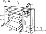
- Fig. 1A shows an image forming apparatus 36, wherein printing is achieved using a wide format inkjet printer.
- the wide-format image forming apparatus 36 comprises a housing 26, wherein the printing assembly, for example the ink jet printing assembly shown in Fig. 1B is placed.
- the image forming apparatus 36 also comprises a storage means for storing image receiving member 28, 30, a delivery station to collect the image receiving member 28, 30 after printing and storage means for marking material 20.
- the delivery station is embodied as a delivery tray 32.
- the delivery station may comprise processing means for processing the image receiving member 28, 30 after printing, e.g. a folder or a puncher.
- the wide-format image forming apparatus 36 furthermore comprises means for receiving print jobs and optionally means for manipulating print jobs. These means may include a user interface unit 24 and/or a control unit 34, for example a computer.
- Images are printed on a image receiving member, for example paper, supplied by a roll 28, 30.
- the roll 28 is supported on the roll support R1, while the roll 30 is supported on the roll support R2.
- cut sheet image receiving members may be used instead of rolls 28, 30 of image receiving member.
- Printed sheets of the image receiving member, cut off from the roll 28, 30, are deposited in the delivery tray 32.
- Each one of the marking materials for use in the printing assembly are stored in holders 20 arranged in fluid connection with the respective print heads for supplying marking material to said print heads.
- the holders 20 may contain a marking material, e.g. a hot melt ink composition.
- Different ones of the holders 20 may comprise a differently colored hot melt ink composition, for example a cyan, a magenta, a yellow or a black ink composition.
- one of the holders 20 may comprise a hot melt cleaning composition according to the present invention.
- the image forming apparatus may print images onto an image receiving member by applying droplets of the hot melt ink composition onto the image receiving member.
- a quantity of the hot melt cleaning composition may be supplied to at least one of the print heads (not shown) for flushing the print head.
- the local user interface unit 24 is integrated to the print engine and may comprise a display unit and a control panel. Alternatively, the control panel may be integrated in the display unit, for example in the form of a touch-screen control panel.
- the local user interface unit 24 is connected to a control unit 34 placed inside the printing apparatus 36.
- the control unit 34 for example a computer, comprises a processor adapted to issue commands to the print engine, for example for controlling the print process.
- the image forming apparatus 36 may optionally be connected to a network N.
- the connection to the network N is diagrammatically shown in the form of a cable 22, but nevertheless, the connection could be wireless.
- the image forming apparatus 36 may receive printing jobs via the network. Further, optionally, the controller of the printer may be provided with a USB port, so printing jobs may be sent to the printer via this USB port.
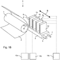
- Fig. 1B shows an ink jet printing assembly 3.
- the ink jet printing assembly 3 comprises supporting means for supporting an image receiving member 2.
- the supporting means are shown in Fig. 1B as a platen 1, but alternatively, the supporting means may be a flat surface.
- the platen 1, as depicted in Fig. 1B is a rotatable drum, which is rotatable about its axis as indicated by arrow A.
- the supporting means may be optionally provided with suction holes for holding the image receiving member in a fixed position with respect to the supporting means.
- the ink jet printing assembly 3 comprises print heads 4a - 4d, mounted on a scanning print carriage 5.
- the scanning print carriage 5 is guided by suitable guiding means 6, 7 to move in reciprocation in the main scanning direction B.
- Each print head 4a - 4d comprises an orifice surface 9, which orifice surface 9 is provided with at least one orifice 8.
- the print heads 4a - 4d are configured to eject droplets of marking material onto the image receiving member 2.
- the platen 1, the carriage 5 and the print heads 4a - 4d are controlled by suitable controlling means 10a, 10b and 10c, respectively.
- the image receiving member 2 may be a medium in web or in sheet form and may be composed of e.g. paper, cardboard, label stock, coated paper, plastic or textile. Alternatively, the image receiving member 2 may also be an intermediate member, endless or not. Examples of endless members, which may be moved cyclically, are a belt or a drum. The image receiving member 2 is moved in the sub-scanning direction A by the platen 1 along four print heads 4a - 4d provided with a fluid marking material.
- a scanning print carriage 5 carries the four print heads 4a - 4d and may be moved in reciprocation in the main scanning direction B parallel to the platen 1, such as to enable scanning of the image receiving member 2 in the main scanning direction B. Only four print heads 4a - 4d are depicted for demonstrating the invention. In practice an arbitrary number of print heads may be employed. In any case, at least one print head 4a - 4d per color of marking material is placed on the scanning print carriage 5. For example, for a black-and-white printer, at least one print head 4a - 4d, usually containing black marking material is present. Alternatively, a black-and-white printer may comprise a white marking material, which is to be applied on a black image-receiving member 2.
- At least one print head 4a - 4d for each of the colors usually black, cyan, magenta and yellow is present.
- black marking material is used more frequently in comparison to differently colored marking material. Therefore, more print heads 4a - 4d containing black marking material may be provided on the scanning print carriage 5 compared to print heads 4a - 4d containing marking material in any of the other colors.
- the print head 4a - 4d containing black marking material may be larger than any of the print heads 4a - 4d, containing a differently colored marking material.
- the carriage 5 is guided by guiding means 6, 7.
- These guiding means 6, 7 may be rods as depicted in Fig. 1B .
- the rods may be driven by suitable driving means (not shown).
- the carriage 5 may be guided by other guiding means, such as an arm being able to move the carriage 5.
- Another alternative is to move the image receiving material 2 in the main scanning direction B.
- Each print head 4a - 4d comprises an orifice surface 9 having at least one orifice 8, in fluid communication with a pressure chamber containing fluid marking material provided in the print head 4a - 4d.
- a number of orifices 8 is arranged in a single linear array parallel to the sub-scanning direction A.
- Eight orifices 8 per print head 4a - 4d are depicted in Fig. 1B , however obviously in a practical embodiment several hundreds of orifices 8 may be provided per print head 4a - 4d, optionally arranged in multiple arrays. As depicted in Fig.
- the respective print heads 4a - 4d are placed parallel to each other such that corresponding orifices 8 of the respective print heads 4a - 4d are positioned in-line in the main scanning direction B.
- a line of image dots in the main scanning direction B may be formed by selectively activating up to four orifices 8, each of them being part of a different print head 4a - 4d.
- This parallel positioning of the print heads 4a - 4d with corresponding in-line placement of the orifices 8 is advantageous to increase productivity and/or improve print quality.
- multiple print heads 4a - 4d may be placed on the print carriage adjacent to each other such that the orifices 8 of the respective print heads 4a - 4d are positioned in a staggered configuration instead of in-line. For instance, this may be done to increase the print resolution or to enlarge the effective print area, which may be addressed in a single scan in the main scanning direction.
- the image dots are formed by ejecting droplets of marking material from the orifices 8.
- marking material Upon ejection of the marking material, some marking material may be spilled and stay on the orifice surface 9 of the print head 4a - 4d.
- the ink present on the orifice surface 9, may negatively influence the ejection of droplets and the placement of these droplets on the image receiving member 2. Therefore, it may be advantageous to remove excess of ink from the orifice surface 9.
- the excess of ink may be removed for example by wiping with a wiper and/or by application of a suitable anti-wetting property of the surface, e.g. provided by a coating.
- Fig. 2 shows a schematic view of a print head 40.
- the print head has a print head body 50.
- the print head 40 comprises at least one orifice 8.
- One orifice 8 is shown in Fig. 2 .
- droplets of a fluid, such as a molten hot melt composition may be jetted.
- the print head 40 comprises a hot melt melting unit 44.
- the hot melt melting unit 44 is adapted to melt a hot melt composition in a solid state.
- the melting unit 44 is provided with heating means (not shown).
- the hot melt composition which may be hot melt cleaning composition or hot melt ink composition may be fed to the melting unit 44 via a hot melt feeding unit (not shown) that feeds quantities of solid hot melt composition to the melt unit 44.
- the hot melt composition may enter the ink channel and flow towards a first filter 46.
- the ink channel is the part of the print head 40 that may contain ink and extends from the melting unit 44 to the orifice 8.
- the first filter 46 is provided to remove contaminants from the hot melt composition, thereby preventing these contaminants to be transferred towards the orifice 8.
- the first filter 46 may selectively retain contaminants, for example based on their particle size.
- the ink reservoir 45 may be provided with a level sensor (not shown) which monitors the level of hot melt composition in the ink reservoir 45. Based on the level of hot melt composition, it may be decided whether hot melt composition should be molten by the melting unit 44 or not.
- the print head 40 as shown in Fig 2 . comprises a second filter 47.
- This second filter 47 is optional. It may be provided to add an additional filter step, such that more contaminant may be retained and not be transferred to the orifice 8.
- the first and the second filter 46, 47 may be filters of the same type or may be filters of a different type. For example, a filter may selectively retain particles exceeding a certain size, or may selectively retain particles having a charge. After the molten hot melt composition has passed the second filter 47, the composition may flow through the ink channel towards a flow restriction 48.
- the hot melt composition arrives in the part of the ink channel in close proximity to the actuating means 41.
- This part of the ink channel is referred to as pressure chamber 43.
- the pressure chamber 43 is situated downstream with respect to the flow restriction 48 and upstream with respect to the nozzle 8.
- the pressure chamber 43 is separated from the actuation means 41 by a flexible membrane 49.
- an actuation means 41 is provided at a side of the membrane 49 opposite to the pressure chamber 43.
- the actuation means 41 may be for example a piezoelectric element.
- the actuation means 41 is driven by suitable driving means (not shown). In operation, the actuation means 41 provide a force to the liquid present at the opposite side of the membrane 49.
- the flow restriction 48 forms a restriction the pressure chamber 43 and the part of the ink channel upstream from the flow restriction 48.
- the flow restriction 48 may damp pressure fluctuations outside of the pressure chamber 43.
- Oce Colorwave 600 print heads that had been incorporated into an Oce Colorwave 600 printer that had been running for 1500 hours, wherein the print heads had been containing cyan hot melt ink (Oce tonerpearls cyan).
- the Oce Colorwave 600 print heads each contained a number of nozzles not functioning properly.
- DMSO 2 was obtained from Sigma-Aldrich. All chemicals were used as received, unless stated otherwise.
- the cleaning tests were carried out as follows: The print heads, comprising nozzle arrays comprising 256 nozzles, and containing cyan hot melt ink, were tested and the number of malfunctioning nozzles was determined. After this test was performed, the ink present in the print head was removed by jetting droplets of the ink. However, some ink remained in the print head after jetting had finished.
- a hot melt composition was added to the print head by adding 51 grams of hot melt composition to the melting unit and melting these pearls.
- the print heads were operated at a temperature of 130°C.
- a rinsing step was performed as follows: 17 grams of the hot melt composition was provided to the melting unit and molten. The hot melt composition was jetted by applying an actuation pulse until all hot melt composition was removed from the print head by jetting. Three rinsing steps were performed. After every rinsing step, the number of malfunctioning nozzles was determined. A nozzle was considered to be malfunctioning, when it was not jetting at all upon application of a pressure pulse or when the jet angle deviated more than 1.5°.
- Hot melt cleaning composition was prepared by melt mixing 80 grams of the carrier material of the Océ Colorwave 600 hot melt ink with 20 grams of DMSO 2 .
- the carrier material of the Océ Colorwave 600 hot melt ink corresponds to the hot melt composition excluding the colorant.
- the resulting cleaning composition was formed into spheres having a diameter of 1.2 cm and solidified.
- a hot melt composition consisting of the carrier material of the Océ Colorwave 600 was used. This comparative example is referred to as CE 2.
- the black Océ Colorwave 600 hot melt ink composition was used. This comparative example is referred to as CE 1.
- non-functioning nozzles may be revived.
- the print head having 196 out of 256 nozzles functioning properly was rinsed using the hot melt composition CE 1, which corresponds to the composition of the Océ Colorwave 600 black toner pearls.
- the print head having 171 out of 256 nozzles functioning properly was rinsed using the hot melt composition CE 2.
- the hot melt cleaning composition according to the present invention is able to clean the print head and to restore the jetting performance of nozzles that were not functioning properly, or were not even functioning at all.
- the performance of the nozzles was restored in a lower number of rinsing steps, compared to other hot melt compositions.
- plurality is defined as two or more than two.
- another is defined as at least a second or more.
- the terms including and/or having, as used herein, are defined as comprising (i.e., open language).
Landscapes
- Chemical & Material Sciences (AREA)
- Life Sciences & Earth Sciences (AREA)
- Engineering & Computer Science (AREA)
- Wood Science & Technology (AREA)
- Organic Chemistry (AREA)
- Materials Engineering (AREA)
- Chemical Kinetics & Catalysis (AREA)
- Oil, Petroleum & Natural Gas (AREA)
- Ink Jet (AREA)
- Detergent Compositions (AREA)
Claims (13)
- Heißschmelzende Reinigungszusammensetzung, welche heißschmelzende Reinigungszusammensetzung bei Zimmertemperatur fest und bei einer erhöhten Temperatur flüssig ist, mit einem heißschmelzenden Lösungsmittel welches Heißschmelz-Lösungsmittel bei Zimmertemperatur fest und bei einer erhöhten Temperatur flüssig ist, und mit einer heißschmelzenden Trägerzusammensetzung, wobei die heißschmelzende Trägerzusammensetzung bei Zimmertemperatur fest und bei einer erhöhten Temperatur flüssig ist,
wobei das heißschmelzende Lösungsmittel ausgewählt ist aus der Gruppe bestehend aus DMSO2, Ethylencarbonat, 1-Tetradecanol, 1-Hexadecanol, 1-Octadecanol, 1-Icosanol, Benzoesäure, Resorcin, Cathechinsäure, Hydrochinon, p-Toluolsulfonsäure, Octadecanamid, 1-6-Hexandiol, Phenylethylenglycol, EDTA, Ethylenglycol-bis(2-aminoethyl)-N,N, N, N-Tetraessigsäure, Diethylentriaminpentaessigsäure, Trans-1,2-Diaminocyclohexan-N,N,N,N-Tetraessigsäure-Monohydrat, und Kronether,
und wobei die heißschmelzende Trägerzusammensetzung ein Geliermittel und wenigstens eine Komponente enthält, die ausgewählt ist aus der Gruppe bestehend aus einem kristallinen abbindenden Material und einem amorph abbindenden Material, wobei das Geliermittel ausgewählt ist aus der Gruppe bestehend Ketonen und Oligoester-Verbindungen. - Heißschmelzende Reinigungszusammensetzung nach Anspruch 1, bei der die heißschmelzende Trägerzusammensetzung ein kristallines abbindendes Material enthält, das kristalline abbindende Material ausgewählt ist aus einem Ester von Benzoesäure, einem Ester eines Benzoesäurederivats, Alkoholen, Sulfonamiden, Bis-Urethanen und Amiden.
- Heißschmelzende Reinigungszusammensetzung nach einem der Ansprüche 1 bis 2, bei der die heißschmelzende Trägerzusammensetzung ein amorphes abbindendes Material enthält und bei der das amorphe abbindende Material eine GlasÜbergangstemperatur (Tg) von 10 bis 50°C, eine Viskosität von weniger als 100 mPa.s bei 150°C und ein Molekulargewicht von weniger als 1000 g/mol hat.
- Heißschmelzende Reinigungszusammensetzung nach einem der Ansprüche 1 bis 3, bei der die heißschmelzende Reinigungszusammensetzung aus einem heißschmelzenden Lösungsmittel und einer heißschmelzenden Trägerzusammensetzung besteht.
- Heißschmelzende Reinigungszusammensetzung nach einem der Ansprüche 1 bis 4, bei der das heißschmelzende Lösungsmittel bei einer Strahltemperatur der heißschmelzenden Reinigungszusammensetzung flüssig ist.
- Heißschmelzende Reinigungszusammensetzung nach einem der vorstehendenden Ansprüche, bei der das heißschmelzende Lösungsmittel Dimethylsulfon ist.
- Kit zum Betreiben und Reinigen einer Tintenstrahlvorrichtung, die einen Drucckopf aufweist, wobei das Kit zwei Einheiten umfasst, wobei eine erste Einheit eine heißschmelzende Reinigungszusammensetzung umfasst, die heißschmelzende Reinigungszusammensetzung bei Zimmertemperatur fest und bei einer erhöhten Temperatur flüssig ist, enthaltend eine erste heißschmelzende Trägerzusammensetzung, wobei die erste heißschmelzende Trägerzusammensetzung bei Zimmertemperatur fest und bei einer erhöhten Temperatur flüssig ist, und ein heißschmelzendes Lösungsmittel, wobei das heißschmelzende Lösungsmittel bei Zimmertemperatur fest und bei einer erhöhten Temperatur flüssig ist, und wobei eine zweite Einheit eine heißschmelzende Tintenzusammensetzung umfasst, die heißschmelzende Tintenzusammensetzung bei Zimmertemperatur fest und bei einer erhöhten Temperatur flüssig ist, enthaltend eine zweite heißschmelzende Trägerzusammensetzung, wobei die zweite heißschmelzende Trägerzusammensetzung bei Zimmertemperatur fest und bei einer erhöhten Temperatur flüssig ist, und ein Färbemittel.
- Kit nach Anspruch 7, bei dem die erste heißschmelzende Trägerzusammensetzung im wesentlichen die gleiche ist wie die zweite heißschmelzende Trägerzusammensetzung.
- Verfahren zur Zubereitung einer heißschmelzenden Reinigungszusammensetzung nach einem der Ansprüche 1 bis 6, welches Verfahren die folgenden Schritte umfasst:- bereitstellen eines heißschmelzenden Lösungsmittels, wobei das heißschmelzende Lösungsmittel bei Zimmertemperatur fest und bei einer erhöhten Temperatur flüssig ist,- bereitstellen einer heißschmelzenden Trägerzusammensetzung, wobei die heißschmelzende Trägerzusammensetzung bei Zimmertemperatur fest und bei einer erhöhten Temperatur flüssig ist,- mischen des heißschmelzenden Lösungsmittels und der heißschmelzenden Trägerzusammensetzung in der Schmelze.
- Verfahren nach Anspruch 9, bei dem das Verfahren weiterhin die folgenden Schritte umfasst:- eingießen der geschmolzenen heißschmelzenden Reinigungszusammensetzung in eine Form.- abkühlen und erstarren lassen der heißschmelzenden Reinigungszusammensetzung in der Form;- trennen der erstarrten heißschmelzenden Reinigungszusammensetzung von der Form.
- Verfahren zum Reinigen eines Druckkopfes, wobei der Druckkopf eine Schmelzeinheit für eine heißschmelzende Zusammensetzung aufweist, welche Schmelzeinheit dazu ausgebildet ist, eine heißschmelzende Zusammensetzung zu schmelzen, wobei die heißschmelzende Zusammensetzung bei Zimmertemperatur fest und bei einer erhöhten Temperatur flüssig ist, wobei der Druckkopf einen Tintenkanal aufweist, die Schmelzeinheit mit einer Zufuhrheit für eine heißschmelzende Zusammensetzung verbunden ist, der Tintenkanal sich von der Schmelzeinheit zu einer Öffnung des Druckkopfes erstreckt, der Tintenkanal dazu ausgebildet ist, eine heißschmelzende Zusammensetzung in einem geschmolzenem Zustand aufzunehmen, welches Verfahren die folgenden Schritte umfasst:- eintragen einer Menge einer heißschmelzenden Reinigungszusammensetzung, welche heißschmelzende Reinigungszusammensetzung bei Zimmertemperatur fest und bei einer erhöhten Temperatur flüssig ist, und einen heißschmelzenden Träger, wobei der heißschmelzende Träger bei Zimmertemperatur fest und bei einer erhöhten Temperatur flüssig ist, und ein heißschmelzendes Lösungsmittel enthält, wobei das heißschmelzende Lösungsmittel bei Zimmertemperatur fest und bei einer erhöhten Temperatur flüssig ist, in die Schmelzeinheit des Druckkopfes;- schmelzen der heißschmelzenden Zusammensetzung- spülen des Tintenkanals des Druckkopfes mit der geschmolzenen heißschmelzenden Reinigungszusammensetzung.
- Verfahren nach Anspruch 11, bei dem die Öffnung in einer Düsenplatte gebildet ist, die eine Vielzahl von Öffnungen aufweist, und wobei das Verfahren weiterhin umfasst:- spülen der Öffnung mit der heißschmelzenden Reinigungszusammensetzung und abwischen der Düsenplatte.
- Verwendung einer heißschmelzenden Reinigungszusammensetzung, wobei die heißschmelzende Reinigungszusammensetzung bei Zimmertemperatur fest und bei einer erhöhten Temperatur flüssig ist, enthaltend ein heißschmelzendes Lösungsmittel, wobei das heißschmelzende Lösungsmittel bei Zimmertemperatur fest und bei einer erhöhten Temperatur flüssig ist, und einen heißschmelzenden Träger, wobei der heißschmelzende Träger bei Zimmertemperatur fest und bei einer erhöhten Temperatur flüssig ist, zum Reinigen von Druckköpfen.
Priority Applications (1)
| Application Number | Priority Date | Filing Date | Title |
|---|---|---|---|
| EP12791471.1A EP2788194B1 (de) | 2011-12-09 | 2012-11-22 | Heissschmelzreinigungszusammensetzung, verfahren zur herstellung einer heissschmelzreinigungszusammensetzung und verwendung dafür |
Applications Claiming Priority (4)
| Application Number | Priority Date | Filing Date | Title |
|---|---|---|---|
| EP11192864 | 2011-12-09 | ||
| EP11196184 | 2011-12-30 | ||
| PCT/EP2012/073357 WO2013083413A1 (en) | 2011-12-09 | 2012-11-22 | Hot melt cleaning composition, method for preparing a hot melt cleaning composition and use thereof |
| EP12791471.1A EP2788194B1 (de) | 2011-12-09 | 2012-11-22 | Heissschmelzreinigungszusammensetzung, verfahren zur herstellung einer heissschmelzreinigungszusammensetzung und verwendung dafür |
Publications (2)
| Publication Number | Publication Date |
|---|---|
| EP2788194A1 EP2788194A1 (de) | 2014-10-15 |
| EP2788194B1 true EP2788194B1 (de) | 2019-10-02 |
Family
ID=47227794
Family Applications (1)
| Application Number | Title | Priority Date | Filing Date |
|---|---|---|---|
| EP12791471.1A Active EP2788194B1 (de) | 2011-12-09 | 2012-11-22 | Heissschmelzreinigungszusammensetzung, verfahren zur herstellung einer heissschmelzreinigungszusammensetzung und verwendung dafür |
Country Status (4)
| Country | Link |
|---|---|
| US (1) | US20140283879A1 (de) |
| EP (1) | EP2788194B1 (de) |
| JP (1) | JP6174595B2 (de) |
| WO (1) | WO2013083413A1 (de) |
Families Citing this family (2)
| Publication number | Priority date | Publication date | Assignee | Title |
|---|---|---|---|---|
| WO2013083413A1 (en) * | 2011-12-09 | 2013-06-13 | Oce-Technologies B.V. | Hot melt cleaning composition, method for preparing a hot melt cleaning composition and use thereof |
| EP3210784B1 (de) * | 2016-02-23 | 2020-04-08 | Canon Production Printing Holding B.V. | Wartungsflüssigkeit für drucker |
Family Cites Families (16)
| Publication number | Priority date | Publication date | Assignee | Title |
|---|---|---|---|---|
| US5122187A (en) * | 1989-06-22 | 1992-06-16 | Xerox Corporation | Hot melt ink compositions |
| DE69120628T2 (de) * | 1990-09-29 | 1996-12-19 | Canon Kk | Verfahren und Vorrichtung zur Tintenstrahlaufzeichnung |
| JP3108788B2 (ja) | 1992-03-18 | 2000-11-13 | セイコーエプソン株式会社 | インクジェットヘッドの洗浄方法、及びその装置 |
| US5385957A (en) * | 1992-08-24 | 1995-01-31 | Videojet Systems International, Inc. | Hotmelt ink jet comprising ionomers having melting points from about 50° C. to about 130° or a softening point below about 80° C., and an image-forming agent |
| JPH1058669A (ja) * | 1996-08-16 | 1998-03-03 | Fuji Photo Film Co Ltd | インクジェット式製版印刷版の作成方法 |
| NL1005174C2 (nl) * | 1997-02-04 | 1998-08-06 | Oce Tech Bv | Inktsamenstelling voor een smeltbare inkt. |
| US5973036A (en) * | 1998-05-08 | 1999-10-26 | Westvaco Corporation | Reversibly-crosslinked-polymers for shear-thinning phase change ink jet inks |
| US6001904A (en) * | 1998-05-08 | 1999-12-14 | Westvaco Corporation | Shear-thinning phase change ink jet inks and method of printing therewith |
| US6110265A (en) * | 1999-04-27 | 2000-08-29 | Xerox Corporation | Ink compositions |
| US6350889B1 (en) * | 1999-06-24 | 2002-02-26 | Arizona Chemical Company | Ink jet printing compositions containing ester-terminated dimer acid-based oligo (ester/amide) |
| NL1021011C2 (nl) * | 2002-07-05 | 2004-01-06 | Oce Tech Bv | Smeltbare inkt voor een inkjet printer en een werkwijze voor het selecteren van een dergelijke inkt. |
| JP2005247983A (ja) * | 2004-03-03 | 2005-09-15 | Sekisui Chem Co Ltd | 湿気硬化型ウレタン系接着剤の洗浄剤 |
| AU2006203245A1 (en) * | 2005-09-01 | 2007-03-15 | Oce-Technologies B.V. | A method for printing a substrate with radiation curable ink, and an ink suitable for application in the said method |
| JP5309453B2 (ja) * | 2007-03-13 | 2013-10-09 | Dic株式会社 | 洗浄剤、及び該洗浄剤を用いた洗浄方法 |
| JP2011028055A (ja) * | 2009-07-27 | 2011-02-10 | Fuji Xerox Co Ltd | 画像形成方法、プロセスカートリッジ、及び、画像形成装置 |
| WO2013083413A1 (en) * | 2011-12-09 | 2013-06-13 | Oce-Technologies B.V. | Hot melt cleaning composition, method for preparing a hot melt cleaning composition and use thereof |
-
2012
- 2012-11-22 WO PCT/EP2012/073357 patent/WO2013083413A1/en active Application Filing
- 2012-11-22 JP JP2014545162A patent/JP6174595B2/ja not_active Expired - Fee Related
- 2012-11-22 EP EP12791471.1A patent/EP2788194B1/de active Active
-
2014
- 2014-05-23 US US14/285,923 patent/US20140283879A1/en not_active Abandoned
Non-Patent Citations (1)
| Title |
|---|
| None * |
Also Published As
| Publication number | Publication date |
|---|---|
| US20140283879A1 (en) | 2014-09-25 |
| JP2015507550A (ja) | 2015-03-12 |
| JP6174595B2 (ja) | 2017-08-02 |
| EP2788194A1 (de) | 2014-10-15 |
| WO2013083413A1 (en) | 2013-06-13 |
Similar Documents
| Publication | Publication Date | Title |
|---|---|---|
| JP4027027B2 (ja) | インク、インクセット、インクカートリッジ、記録ユニット、画像記録装置およびインクジェット記録方法 | |
| JP5146041B2 (ja) | インクジェットプリンタ及びインクジェットヘッド洗浄液 | |
| EP1834783B1 (de) | Verfahren zum reinigen eines kopfes und tintenstrahlaufzeichnungsgerät | |
| US8646873B2 (en) | Ink jet recording apparatus | |
| JPH06322307A (ja) | インク及びこれを用いたインクジェット記録方法 | |
| US9051487B2 (en) | Hot melt ink composition, method for preparing a hot melt ink composition and use thereof | |
| JP6314523B2 (ja) | インクジェット記録方法 | |
| EP2788194B1 (de) | Heissschmelzreinigungszusammensetzung, verfahren zur herstellung einer heissschmelzreinigungszusammensetzung und verwendung dafür | |
| KR20050075299A (ko) | 기록액, 액체 카트리지, 액체 토출 카트리지, 액체 토출장치 및 액체 토출 방법 | |
| US20150124030A1 (en) | Hot melt ink composition, method for preparing a hot melt ink composition and use of a hot melt ink composition | |
| JP2003205619A (ja) | インクジェットプリンタ | |
| JP5811323B2 (ja) | インクジェット記録装置およびインク組成物 | |
| JP3406917B2 (ja) | インクジェット記録方法、インクジェット記録装置およびブリーディングの軽減方法 | |
| JP2017213798A (ja) | インクジェット記録方法及びインクジェット記録装置 | |
| JPH09151348A (ja) | インクセット、インクジェット記録方法及びインクジェット機器 | |
| JP2000351925A (ja) | インクジェット用水性インクおよびインクジェット記録方法 | |
| US20080007588A1 (en) | Recording liquid, recording method using the same and liquid cartridge | |
| JP3969946B2 (ja) | インクセット、これを用いるインクジェット記録方法、インクジェット記録装置、インクカートリッジ、記録ユニット及びブリードの緩和方法 | |
| JP3969945B2 (ja) | インクセット、これを用いるインクジェット記録方法、記録ユニット、インクカートリッジ、インクジェット記録装置及びブリーディング緩和方法 | |
| JP2005144737A (ja) | インクジェットプリンタ及び記録ヘッドのクリーニング方法 | |
| JP2008063540A (ja) | 記録液製造装置及び記録液の製造方法 | |
| US10501650B2 (en) | Ink jet recording method and ink jet recording apparatus | |
| JP2003205621A (ja) | インクジェットプリンタ及び記録方法 | |
| JPH06248208A (ja) | インク及びこれを用いた画像形成方法 | |
| JP2003191479A (ja) | インクジェット記録装置 |
Legal Events
| Date | Code | Title | Description |
|---|---|---|---|
| PUAI | Public reference made under article 153(3) epc to a published international application that has entered the european phase |
Free format text: ORIGINAL CODE: 0009012 |
|
| 17P | Request for examination filed |
Effective date: 20140709 |
|
| AK | Designated contracting states |
Kind code of ref document: A1 Designated state(s): AL AT BE BG CH CY CZ DE DK EE ES FI FR GB GR HR HU IE IS IT LI LT LU LV MC MK MT NL NO PL PT RO RS SE SI SK SM TR |
|
| DAX | Request for extension of the european patent (deleted) | ||
| STAA | Information on the status of an ep patent application or granted ep patent |
Free format text: STATUS: EXAMINATION IS IN PROGRESS |
|
| 17Q | First examination report despatched |
Effective date: 20171201 |
|
| REG | Reference to a national code |
Ref country code: DE Ref legal event code: R079 Ref document number: 602012064562 Country of ref document: DE Free format text: PREVIOUS MAIN CLASS: B41J0002000000 Ipc: C09D0011340000 |
|
| RIC1 | Information provided on ipc code assigned before grant |
Ipc: C09D 11/34 20140101AFI20190327BHEP Ipc: C09D 11/40 20140101ALI20190327BHEP Ipc: B41J 2/00 20060101ALI20190327BHEP |
|
| GRAP | Despatch of communication of intention to grant a patent |
Free format text: ORIGINAL CODE: EPIDOSNIGR1 |
|
| STAA | Information on the status of an ep patent application or granted ep patent |
Free format text: STATUS: GRANT OF PATENT IS INTENDED |
|
| INTG | Intention to grant announced |
Effective date: 20190506 |
|
| GRAS | Grant fee paid |
Free format text: ORIGINAL CODE: EPIDOSNIGR3 |
|
| GRAA | (expected) grant |
Free format text: ORIGINAL CODE: 0009210 |
|
| STAA | Information on the status of an ep patent application or granted ep patent |
Free format text: STATUS: THE PATENT HAS BEEN GRANTED |
|
| AK | Designated contracting states |
Kind code of ref document: B1 Designated state(s): AL AT BE BG CH CY CZ DE DK EE ES FI FR GB GR HR HU IE IS IT LI LT LU LV MC MK MT NL NO PL PT RO RS SE SI SK SM TR |
|
| REG | Reference to a national code |
Ref country code: GB Ref legal event code: FG4D |
|
| REG | Reference to a national code |
Ref country code: CH Ref legal event code: EP Ref country code: AT Ref legal event code: REF Ref document number: 1186140 Country of ref document: AT Kind code of ref document: T Effective date: 20191015 |
|
| REG | Reference to a national code |
Ref country code: DE Ref legal event code: R096 Ref document number: 602012064562 Country of ref document: DE |
|
| REG | Reference to a national code |
Ref country code: IE Ref legal event code: FG4D |
|
| REG | Reference to a national code |
Ref country code: NL Ref legal event code: FP |
|
| REG | Reference to a national code |
Ref country code: LT Ref legal event code: MG4D |
|
| REG | Reference to a national code |
Ref country code: AT Ref legal event code: MK05 Ref document number: 1186140 Country of ref document: AT Kind code of ref document: T Effective date: 20191002 |
|
| PG25 | Lapsed in a contracting state [announced via postgrant information from national office to epo] |
Ref country code: PT Free format text: LAPSE BECAUSE OF FAILURE TO SUBMIT A TRANSLATION OF THE DESCRIPTION OR TO PAY THE FEE WITHIN THE PRESCRIBED TIME-LIMIT Effective date: 20200203 Ref country code: GR Free format text: LAPSE BECAUSE OF FAILURE TO SUBMIT A TRANSLATION OF THE DESCRIPTION OR TO PAY THE FEE WITHIN THE PRESCRIBED TIME-LIMIT Effective date: 20200103 Ref country code: NO Free format text: LAPSE BECAUSE OF FAILURE TO SUBMIT A TRANSLATION OF THE DESCRIPTION OR TO PAY THE FEE WITHIN THE PRESCRIBED TIME-LIMIT Effective date: 20200102 Ref country code: BG Free format text: LAPSE BECAUSE OF FAILURE TO SUBMIT A TRANSLATION OF THE DESCRIPTION OR TO PAY THE FEE WITHIN THE PRESCRIBED TIME-LIMIT Effective date: 20200102 Ref country code: FI Free format text: LAPSE BECAUSE OF FAILURE TO SUBMIT A TRANSLATION OF THE DESCRIPTION OR TO PAY THE FEE WITHIN THE PRESCRIBED TIME-LIMIT Effective date: 20191002 Ref country code: LV Free format text: LAPSE BECAUSE OF FAILURE TO SUBMIT A TRANSLATION OF THE DESCRIPTION OR TO PAY THE FEE WITHIN THE PRESCRIBED TIME-LIMIT Effective date: 20191002 Ref country code: SE Free format text: LAPSE BECAUSE OF FAILURE TO SUBMIT A TRANSLATION OF THE DESCRIPTION OR TO PAY THE FEE WITHIN THE PRESCRIBED TIME-LIMIT Effective date: 20191002 Ref country code: AT Free format text: LAPSE BECAUSE OF FAILURE TO SUBMIT A TRANSLATION OF THE DESCRIPTION OR TO PAY THE FEE WITHIN THE PRESCRIBED TIME-LIMIT Effective date: 20191002 Ref country code: PL Free format text: LAPSE BECAUSE OF FAILURE TO SUBMIT A TRANSLATION OF THE DESCRIPTION OR TO PAY THE FEE WITHIN THE PRESCRIBED TIME-LIMIT Effective date: 20191002 Ref country code: ES Free format text: LAPSE BECAUSE OF FAILURE TO SUBMIT A TRANSLATION OF THE DESCRIPTION OR TO PAY THE FEE WITHIN THE PRESCRIBED TIME-LIMIT Effective date: 20191002 Ref country code: LT Free format text: LAPSE BECAUSE OF FAILURE TO SUBMIT A TRANSLATION OF THE DESCRIPTION OR TO PAY THE FEE WITHIN THE PRESCRIBED TIME-LIMIT Effective date: 20191002 |
|
| PG25 | Lapsed in a contracting state [announced via postgrant information from national office to epo] |
Ref country code: IS Free format text: LAPSE BECAUSE OF FAILURE TO SUBMIT A TRANSLATION OF THE DESCRIPTION OR TO PAY THE FEE WITHIN THE PRESCRIBED TIME-LIMIT Effective date: 20200224 Ref country code: CZ Free format text: LAPSE BECAUSE OF FAILURE TO SUBMIT A TRANSLATION OF THE DESCRIPTION OR TO PAY THE FEE WITHIN THE PRESCRIBED TIME-LIMIT Effective date: 20191002 Ref country code: HR Free format text: LAPSE BECAUSE OF FAILURE TO SUBMIT A TRANSLATION OF THE DESCRIPTION OR TO PAY THE FEE WITHIN THE PRESCRIBED TIME-LIMIT Effective date: 20191002 Ref country code: RS Free format text: LAPSE BECAUSE OF FAILURE TO SUBMIT A TRANSLATION OF THE DESCRIPTION OR TO PAY THE FEE WITHIN THE PRESCRIBED TIME-LIMIT Effective date: 20191002 |
|
| PG25 | Lapsed in a contracting state [announced via postgrant information from national office to epo] |
Ref country code: AL Free format text: LAPSE BECAUSE OF FAILURE TO SUBMIT A TRANSLATION OF THE DESCRIPTION OR TO PAY THE FEE WITHIN THE PRESCRIBED TIME-LIMIT Effective date: 20191002 |
|
| REG | Reference to a national code |
Ref country code: CH Ref legal event code: PL |
|
| REG | Reference to a national code |
Ref country code: DE Ref legal event code: R097 Ref document number: 602012064562 Country of ref document: DE |
|
| PG2D | Information on lapse in contracting state deleted |
Ref country code: IS |
|
| PG25 | Lapsed in a contracting state [announced via postgrant information from national office to epo] |
Ref country code: DK Free format text: LAPSE BECAUSE OF FAILURE TO SUBMIT A TRANSLATION OF THE DESCRIPTION OR TO PAY THE FEE WITHIN THE PRESCRIBED TIME-LIMIT Effective date: 20191002 Ref country code: LU Free format text: LAPSE BECAUSE OF NON-PAYMENT OF DUE FEES Effective date: 20191122 Ref country code: EE Free format text: LAPSE BECAUSE OF FAILURE TO SUBMIT A TRANSLATION OF THE DESCRIPTION OR TO PAY THE FEE WITHIN THE PRESCRIBED TIME-LIMIT Effective date: 20191002 Ref country code: CH Free format text: LAPSE BECAUSE OF NON-PAYMENT OF DUE FEES Effective date: 20191130 Ref country code: RO Free format text: LAPSE BECAUSE OF FAILURE TO SUBMIT A TRANSLATION OF THE DESCRIPTION OR TO PAY THE FEE WITHIN THE PRESCRIBED TIME-LIMIT Effective date: 20191002 Ref country code: LI Free format text: LAPSE BECAUSE OF NON-PAYMENT OF DUE FEES Effective date: 20191130 Ref country code: MC Free format text: LAPSE BECAUSE OF FAILURE TO SUBMIT A TRANSLATION OF THE DESCRIPTION OR TO PAY THE FEE WITHIN THE PRESCRIBED TIME-LIMIT Effective date: 20191002 Ref country code: IS Free format text: LAPSE BECAUSE OF FAILURE TO SUBMIT A TRANSLATION OF THE DESCRIPTION OR TO PAY THE FEE WITHIN THE PRESCRIBED TIME-LIMIT Effective date: 20200202 |
|
| PLBE | No opposition filed within time limit |
Free format text: ORIGINAL CODE: 0009261 |
|
| STAA | Information on the status of an ep patent application or granted ep patent |
Free format text: STATUS: NO OPPOSITION FILED WITHIN TIME LIMIT |
|
| REG | Reference to a national code |
Ref country code: BE Ref legal event code: MM Effective date: 20191130 |
|
| PG25 | Lapsed in a contracting state [announced via postgrant information from national office to epo] |
Ref country code: SM Free format text: LAPSE BECAUSE OF FAILURE TO SUBMIT A TRANSLATION OF THE DESCRIPTION OR TO PAY THE FEE WITHIN THE PRESCRIBED TIME-LIMIT Effective date: 20191002 Ref country code: IT Free format text: LAPSE BECAUSE OF FAILURE TO SUBMIT A TRANSLATION OF THE DESCRIPTION OR TO PAY THE FEE WITHIN THE PRESCRIBED TIME-LIMIT Effective date: 20191002 Ref country code: SK Free format text: LAPSE BECAUSE OF FAILURE TO SUBMIT A TRANSLATION OF THE DESCRIPTION OR TO PAY THE FEE WITHIN THE PRESCRIBED TIME-LIMIT Effective date: 20191002 |
|
| 26N | No opposition filed |
Effective date: 20200703 |
|
| GBPC | Gb: european patent ceased through non-payment of renewal fee |
Effective date: 20200102 |
|
| PG25 | Lapsed in a contracting state [announced via postgrant information from national office to epo] |
Ref country code: GB Free format text: LAPSE BECAUSE OF NON-PAYMENT OF DUE FEES Effective date: 20200102 Ref country code: IE Free format text: LAPSE BECAUSE OF NON-PAYMENT OF DUE FEES Effective date: 20191122 Ref country code: FR Free format text: LAPSE BECAUSE OF NON-PAYMENT OF DUE FEES Effective date: 20191202 |
|
| PG25 | Lapsed in a contracting state [announced via postgrant information from national office to epo] |
Ref country code: BE Free format text: LAPSE BECAUSE OF NON-PAYMENT OF DUE FEES Effective date: 20191130 Ref country code: SI Free format text: LAPSE BECAUSE OF FAILURE TO SUBMIT A TRANSLATION OF THE DESCRIPTION OR TO PAY THE FEE WITHIN THE PRESCRIBED TIME-LIMIT Effective date: 20191002 |
|
| PG25 | Lapsed in a contracting state [announced via postgrant information from national office to epo] |
Ref country code: CY Free format text: LAPSE BECAUSE OF FAILURE TO SUBMIT A TRANSLATION OF THE DESCRIPTION OR TO PAY THE FEE WITHIN THE PRESCRIBED TIME-LIMIT Effective date: 20191002 |
|
| PG25 | Lapsed in a contracting state [announced via postgrant information from national office to epo] |
Ref country code: HU Free format text: LAPSE BECAUSE OF FAILURE TO SUBMIT A TRANSLATION OF THE DESCRIPTION OR TO PAY THE FEE WITHIN THE PRESCRIBED TIME-LIMIT; INVALID AB INITIO Effective date: 20121122 Ref country code: MT Free format text: LAPSE BECAUSE OF FAILURE TO SUBMIT A TRANSLATION OF THE DESCRIPTION OR TO PAY THE FEE WITHIN THE PRESCRIBED TIME-LIMIT Effective date: 20191002 |
|
| PGFP | Annual fee paid to national office [announced via postgrant information from national office to epo] |
Ref country code: DE Payment date: 20211118 Year of fee payment: 10 |
|
| PG25 | Lapsed in a contracting state [announced via postgrant information from national office to epo] |
Ref country code: TR Free format text: LAPSE BECAUSE OF FAILURE TO SUBMIT A TRANSLATION OF THE DESCRIPTION OR TO PAY THE FEE WITHIN THE PRESCRIBED TIME-LIMIT Effective date: 20191002 |
|
| PG25 | Lapsed in a contracting state [announced via postgrant information from national office to epo] |
Ref country code: MK Free format text: LAPSE BECAUSE OF FAILURE TO SUBMIT A TRANSLATION OF THE DESCRIPTION OR TO PAY THE FEE WITHIN THE PRESCRIBED TIME-LIMIT Effective date: 20191002 |
|
| PGFP | Annual fee paid to national office [announced via postgrant information from national office to epo] |
Ref country code: NL Payment date: 20221130 Year of fee payment: 11 |
|
| REG | Reference to a national code |
Ref country code: DE Ref legal event code: R119 Ref document number: 602012064562 Country of ref document: DE |
|
| PG25 | Lapsed in a contracting state [announced via postgrant information from national office to epo] |
Ref country code: DE Free format text: LAPSE BECAUSE OF NON-PAYMENT OF DUE FEES Effective date: 20230601 |