EP2787215B1 - Verfahren zum Betrieb eines Verbrennungsmotors - Google Patents
Verfahren zum Betrieb eines Verbrennungsmotors Download PDFInfo
- Publication number
- EP2787215B1 EP2787215B1 EP14001227.9A EP14001227A EP2787215B1 EP 2787215 B1 EP2787215 B1 EP 2787215B1 EP 14001227 A EP14001227 A EP 14001227A EP 2787215 B1 EP2787215 B1 EP 2787215B1
- Authority
- EP
- European Patent Office
- Prior art keywords
- ignition point
- ignition
- engine
- closing
- zzp2
- Prior art date
- Legal status (The legal status is an assumption and is not a legal conclusion. Google has not performed a legal analysis and makes no representation as to the accuracy of the status listed.)
- Active
Links
- 238000002485 combustion reaction Methods 0.000 title claims description 111
- 238000000034 method Methods 0.000 title claims description 35
- 230000006837 decompression Effects 0.000 claims description 52
- 238000010586 diagram Methods 0.000 description 9
- 239000000446 fuel Substances 0.000 description 9
- 239000000203 mixture Substances 0.000 description 5
- 239000007858 starting material Substances 0.000 description 5
- 230000001133 acceleration Effects 0.000 description 3
- 230000006835 compression Effects 0.000 description 2
- 238000007906 compression Methods 0.000 description 2
- 238000010276 construction Methods 0.000 description 2
- 238000004519 manufacturing process Methods 0.000 description 2
- 241001124569 Lycaenidae Species 0.000 description 1
- 238000001816 cooling Methods 0.000 description 1
- 230000001419 dependent effect Effects 0.000 description 1
- 230000002349 favourable effect Effects 0.000 description 1
- 238000010304 firing Methods 0.000 description 1
- 239000007789 gas Substances 0.000 description 1
- 238000012544 monitoring process Methods 0.000 description 1
- 230000001737 promoting effect Effects 0.000 description 1
- 230000001681 protective effect Effects 0.000 description 1
- 230000001846 repelling effect Effects 0.000 description 1
- 230000001960 triggered effect Effects 0.000 description 1
Images


Classifications
-
- F—MECHANICAL ENGINEERING; LIGHTING; HEATING; WEAPONS; BLASTING
- F02—COMBUSTION ENGINES; HOT-GAS OR COMBUSTION-PRODUCT ENGINE PLANTS
- F02N—STARTING OF COMBUSTION ENGINES; STARTING AIDS FOR SUCH ENGINES, NOT OTHERWISE PROVIDED FOR
- F02N19/00—Starting aids for combustion engines, not otherwise provided for
- F02N19/004—Aiding engine start by using decompression means or variable valve actuation
-
- F—MECHANICAL ENGINEERING; LIGHTING; HEATING; WEAPONS; BLASTING
- F02—COMBUSTION ENGINES; HOT-GAS OR COMBUSTION-PRODUCT ENGINE PLANTS
- F02P—IGNITION, OTHER THAN COMPRESSION IGNITION, FOR INTERNAL-COMBUSTION ENGINES; TESTING OF IGNITION TIMING IN COMPRESSION-IGNITION ENGINES
- F02P5/00—Advancing or retarding ignition; Control therefor
- F02P5/04—Advancing or retarding ignition; Control therefor automatically, as a function of the working conditions of the engine or vehicle or of the atmospheric conditions
- F02P5/145—Advancing or retarding ignition; Control therefor automatically, as a function of the working conditions of the engine or vehicle or of the atmospheric conditions using electrical means
- F02P5/15—Digital data processing
- F02P5/1502—Digital data processing using one central computing unit
- F02P5/1506—Digital data processing using one central computing unit with particular means during starting
-
- F—MECHANICAL ENGINEERING; LIGHTING; HEATING; WEAPONS; BLASTING
- F02—COMBUSTION ENGINES; HOT-GAS OR COMBUSTION-PRODUCT ENGINE PLANTS
- F02P—IGNITION, OTHER THAN COMPRESSION IGNITION, FOR INTERNAL-COMBUSTION ENGINES; TESTING OF IGNITION TIMING IN COMPRESSION-IGNITION ENGINES
- F02P5/00—Advancing or retarding ignition; Control therefor
- F02P5/04—Advancing or retarding ignition; Control therefor automatically, as a function of the working conditions of the engine or vehicle or of the atmospheric conditions
- F02P5/145—Advancing or retarding ignition; Control therefor automatically, as a function of the working conditions of the engine or vehicle or of the atmospheric conditions using electrical means
- F02P5/15—Digital data processing
- F02P5/1502—Digital data processing using one central computing unit
- F02P5/1508—Digital data processing using one central computing unit with particular means during idling
-
- F—MECHANICAL ENGINEERING; LIGHTING; HEATING; WEAPONS; BLASTING
- F02—COMBUSTION ENGINES; HOT-GAS OR COMBUSTION-PRODUCT ENGINE PLANTS
- F02P—IGNITION, OTHER THAN COMPRESSION IGNITION, FOR INTERNAL-COMBUSTION ENGINES; TESTING OF IGNITION TIMING IN COMPRESSION-IGNITION ENGINES
- F02P5/00—Advancing or retarding ignition; Control therefor
- F02P5/04—Advancing or retarding ignition; Control therefor automatically, as a function of the working conditions of the engine or vehicle or of the atmospheric conditions
- F02P5/145—Advancing or retarding ignition; Control therefor automatically, as a function of the working conditions of the engine or vehicle or of the atmospheric conditions using electrical means
- F02P5/15—Digital data processing
- F02P5/1502—Digital data processing using one central computing unit
- F02P5/1512—Digital data processing using one central computing unit with particular means concerning an individual cylinder
-
- F—MECHANICAL ENGINEERING; LIGHTING; HEATING; WEAPONS; BLASTING
- F02—COMBUSTION ENGINES; HOT-GAS OR COMBUSTION-PRODUCT ENGINE PLANTS
- F02P—IGNITION, OTHER THAN COMPRESSION IGNITION, FOR INTERNAL-COMBUSTION ENGINES; TESTING OF IGNITION TIMING IN COMPRESSION-IGNITION ENGINES
- F02P5/00—Advancing or retarding ignition; Control therefor
- F02P5/04—Advancing or retarding ignition; Control therefor automatically, as a function of the working conditions of the engine or vehicle or of the atmospheric conditions
- F02P5/145—Advancing or retarding ignition; Control therefor automatically, as a function of the working conditions of the engine or vehicle or of the atmospheric conditions using electrical means
- F02P5/15—Digital data processing
- F02P5/153—Digital data processing dependent on combustion pressure
-
- F—MECHANICAL ENGINEERING; LIGHTING; HEATING; WEAPONS; BLASTING
- F02—COMBUSTION ENGINES; HOT-GAS OR COMBUSTION-PRODUCT ENGINE PLANTS
- F02D—CONTROLLING COMBUSTION ENGINES
- F02D13/00—Controlling the engine output power by varying inlet or exhaust valve operating characteristics, e.g. timing
- F02D13/02—Controlling the engine output power by varying inlet or exhaust valve operating characteristics, e.g. timing during engine operation
- F02D13/0276—Actuation of an additional valve for a special application, e.g. for decompression, exhaust gas recirculation or cylinder scavenging
-
- F—MECHANICAL ENGINEERING; LIGHTING; HEATING; WEAPONS; BLASTING
- F02—COMBUSTION ENGINES; HOT-GAS OR COMBUSTION-PRODUCT ENGINE PLANTS
- F02D—CONTROLLING COMBUSTION ENGINES
- F02D2400/00—Control systems adapted for specific engine types; Special features of engine control systems not otherwise provided for; Power supply, connectors or cabling for engine control systems
- F02D2400/06—Small engines with electronic control, e.g. for hand held tools
-
- F—MECHANICAL ENGINEERING; LIGHTING; HEATING; WEAPONS; BLASTING
- F02—COMBUSTION ENGINES; HOT-GAS OR COMBUSTION-PRODUCT ENGINE PLANTS
- F02D—CONTROLLING COMBUSTION ENGINES
- F02D35/00—Controlling engines, dependent on conditions exterior or interior to engines, not otherwise provided for
- F02D35/02—Controlling engines, dependent on conditions exterior or interior to engines, not otherwise provided for on interior conditions
- F02D35/023—Controlling engines, dependent on conditions exterior or interior to engines, not otherwise provided for on interior conditions by determining the cylinder pressure
-
- F—MECHANICAL ENGINEERING; LIGHTING; HEATING; WEAPONS; BLASTING
- F02—COMBUSTION ENGINES; HOT-GAS OR COMBUSTION-PRODUCT ENGINE PLANTS
- F02D—CONTROLLING COMBUSTION ENGINES
- F02D41/00—Electrical control of supply of combustible mixture or its constituents
- F02D41/02—Circuit arrangements for generating control signals
- F02D41/14—Introducing closed-loop corrections
- F02D41/1497—With detection of the mechanical response of the engine
-
- F—MECHANICAL ENGINEERING; LIGHTING; HEATING; WEAPONS; BLASTING
- F02—COMBUSTION ENGINES; HOT-GAS OR COMBUSTION-PRODUCT ENGINE PLANTS
- F02N—STARTING OF COMBUSTION ENGINES; STARTING AIDS FOR SUCH ENGINES, NOT OTHERWISE PROVIDED FOR
- F02N3/00—Other muscle-operated starting apparatus
- F02N3/02—Other muscle-operated starting apparatus having pull-cords
-
- Y—GENERAL TAGGING OF NEW TECHNOLOGICAL DEVELOPMENTS; GENERAL TAGGING OF CROSS-SECTIONAL TECHNOLOGIES SPANNING OVER SEVERAL SECTIONS OF THE IPC; TECHNICAL SUBJECTS COVERED BY FORMER USPC CROSS-REFERENCE ART COLLECTIONS [XRACs] AND DIGESTS
- Y02—TECHNOLOGIES OR APPLICATIONS FOR MITIGATION OR ADAPTATION AGAINST CLIMATE CHANGE
- Y02T—CLIMATE CHANGE MITIGATION TECHNOLOGIES RELATED TO TRANSPORTATION
- Y02T10/00—Road transport of goods or passengers
- Y02T10/10—Internal combustion engine [ICE] based vehicles
- Y02T10/40—Engine management systems
Definitions
- the invention relates to a method for operating an internal combustion engine of the type specified in the preamble of claim 1.
- the ignition of internal combustion engines is usually controlled by a control device.
- the ignition takes place at a comparatively late ignition point.
- idling is to be achieved in that the speed does not rise excessively, so that there is a constant idle speed and only small speed fluctuations in idle.
- the combustion pressure which prevails due to the late ignition timing, is not always reliable enough to close the decompression valve.
- tight tolerances must be adhered to the decompression valve, which leads to a more complicated production of the decompression valve.
- the invention has for its object to provide a method for operating an internal combustion engine, with which a simple design decompression valve can be reliably closed.
- ignition takes place at a Sch thoroughlyzündzeittician is about 5 ° crankshaft angle before the earliest ignition, in particular at least about 5 ° crankshaft angle is before the earliest ignition timing.
- the earliest ignition time is the earliest ignition point provided after the idle control of the ignition timing.
- the ignition is therefore adjusted in the idle speed range for at least one engine cycle to "early". In this case, an advance of the ignition timing may be sufficient for a single engine cycle.
- the ignition timing for several engine cycles, in particular for several consecutive engine cycles to "early” to adjust to ensure that at least a sufficiently strong combustion takes place, which leads to a safe closing of the decompression valve.
- the idle control can provide a comparatively late ignition timing, which ensures that a smooth running of the engine results in the idling speed range and reliably prevents a repelling of the engine, so driving the motor in reverse direction.
- the ignition timing provided after the idling control need not be adjusted to the closing pressure of the decompression valve. In the at least one engine cycle in which the ignition takes place at the Sch thoroughlyzündzeittician, there is a stronger combustion in the combustion chamber. As a result, a higher pressure in the combustion chamber is achieved, which leads to a safe closing of the decompression valve. An excessively complex construction of the decompression valve or an excessively accurate production of the decompression valve is therefore not necessary.
- the inventive method can be used in any type of internal combustion engine with a decompression valve, z.
- Example in a conventional internal combustion engine with a mechanical carburetor, in an internal combustion engine with electronically zuzu messengerder fuel quantity or the like. Motor.
- the method according to the invention is used in two-stroke engines with recoil starter or electric starter.
- the Sch thoroughlyzündzeittician is advantageously at most about 40 ° crankshaft angle before the earliest ignition. As a result, a setback of the engine can still be safely avoided.
- the Sch thoroughlyzündzeittician is advantageously at least about 10 ° crankshaft angle, in particular about 20 ° crankshaft angle before the earliest ignition timing. As a result, a sufficiently high combustion pressure is achieved in the combustion chamber, so that the decompression valve closes securely.
- the ignition timing is determined based on the idle control to 0 ° to about 20 ° crankshaft angle before top dead center and the Schörndzeittician is about 25 ° to about 50 ° crankshaft angle before top dead center.
- the at least one engine cycle in which the ignition takes place at Sch resonatezündzeittician takes place advantageously during the first 100 engine cycles, in particular during the first 50 engine cycles after the starting process.
- the starting process here means the starting operation of the internal combustion engine until the first combustion in the combustion chamber takes place. After the first combustion, the engine is idled until acceleration occurs from the idle speed range.
- this engine cycle is preceded by at least one engine cycle to which no ignition takes place.
- the at least one engine cycle, to which the ignition takes place at the closing ignition time is preceded by several engine cycles without ignition.
- the internal combustion engine is ignited to the Sch thoroughlyzündzeittician until combustion has taken place in the combustion chamber. This ensures that the Decompression valve is closed.
- the determination of whether combustion has taken place can be carried out in a simple manner by monitoring the rotational speed of the crankshaft. If the speed increases more during the downstroke of the piston, ie if the acceleration exceeds a limit, combustion took place. However, it can also be provided to determine whether a combustion has taken place via a pressure sensor in the combustion chamber. It may also be provided to monitor whether the decompression valve is closed and to carry out the ignition at Sch thoroughlyzündzeittician until the decompression valve has closed.
- the Sch. joszündzeittician may be a fixed, stored in the control device ignition. However, it can also be provided that the Sch thoroughlyzündzeit Vietnamese is determined based on a scheduled after idle control ignition. For example, the ignition point provided after the idling control can be adjusted to "early" by a number of degrees of crankshaft angle predefined in the control device. The ignition point provided after the idling control may be the ignition timing for the following engine cycle or an ignition timing of a preceding engine cycle. The controller may provide for suspending idle control at the engine cycle (s) at which ignition occurs at the lock ignition timing. However, the control device after the idle control can also be overridden or the scheduled ignition timing can be shifted to an earlier ignition timing.
- the idling control advantageously controls the ignition timing as a function of the rotational speed of the internal combustion engine. It is particularly provided that the ignition is adjusted with increasing speed to "late”. As a result, a smooth running of the engine is achieved at idle with low speed fluctuations. However, it may also be provided that the idle control the ignition timing to a fixed constant ignition timing.
- the decompression valve opens into a pressure relief chamber.
- the pressure relief space is in particular the environment or the interior of a crankcase of the internal combustion engine.
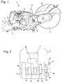
- Fig. 1 shows an embodiment of a portable, hand-held implement a power grinder 1.
- the method for operating an internal combustion engine described below can also in internal combustion engines for other applications, especially in internal combustion engines in other implements such as chainsaws, brushcutters, blowers, sprayers, harvesters, Lawnmowers or the like can be used.
- the power cutter 1 has a housing 2, on which two handles for guiding the cutting grinder 1 during operation, namely a rear handle 3 and a handle tube 6 are fixed.
- a throttle lever 4 and a throttle lock 5 are pivotally mounted.
- a boom 8 projects forward, at the free end of a blade 9 is rotatably mounted.
- the cutting disc 9 is covered by a protective cover 12 over part of its circumference.
- internal combustion engine 7 is arranged in the housing 2 .
- the cutting disc 9 is driven in rotation by the engine 7.
- Fig. 2 schematically shown Anwerfvoruze 10, which has a Anwerfgriff 11.
- Fig. 1 shows, the Anwerfgriff 11 protrudes from the housing 2 of the cutting machine.
- the internal combustion engine 7, which in Fig. 2 is shown schematically, is advantageous a single-cylinder engine, in particular a Gemischgeschmierter engine, preferably a two-stroke engine.
- the internal combustion engine 7 has a piston 15 which rotatably drives a crankshaft 17 about a rotation axis 18 via a connecting rod 16.
- a flywheel 19 is fixed.
- the flywheel 19 may be formed as a fan and have fan blades for promoting cooling air for the engine 7.
- a centrifugal clutch 20 is fixed to the crankshaft 17.
- the centrifugal clutch 20 has with the Crankshaft 17 rotatably connected, not shown centrifugal weights, which cooperate with a clutch drum 21.
- the clutch drum 21 is rotatably connected to a drive pulley 13, on which a drive belt 14 is arranged.
- the drive belt 14 extends in the boom 8 and drives the blade 9 at.
- Fig. 2 shows, the Anwerfvoruze 10 adjacent to the drive pulley 13 is arranged on the boom 8 and acts on the crankshaft sixteenth
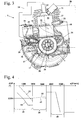
- Fig. 3 shows the structure of the internal combustion engine 7 in detail.
- the engine 7 has a cylinder 27 into which a decompression valve 22 and a spark plug 23 protrude.
- the control of the spark plug 23 via a control device 24.
- the control device 24 also controls a fuel valve 25, which is arranged in the exemplary embodiment of a crankcase 28 of the engine 7.
- the fuel valve 25 supplies fuel under low pressure into the interior of the crankcase 28.
- the interior of the crankcase 28 is connected via an overflow 34 with a cylinder 27 formed in the combustion chamber 29.
- the overflow channel 34 is divided into several, in the embodiment in four branches, which open into a respective overflow window 35 into the combustion chamber 29. Also, a different number or design of one or more overflow channels 34 may be advantageous.
- the overflow windows 35 are of the in Fig. 3 controlled schematically shown piston 15.
- an intake passage 32 opens into the crankcase 28 with an inlet 30 also controlled by the piston 15.
- the intake passage 32 is connected to the interior of the crankcase 28 in the region of top dead center of the piston 15.
- a throttle element 31 is arranged, which is formed in the embodiment as a pivotally mounted throttle valve. From the combustion chamber 29 leads a likewise controlled by the piston 15 outlet 33, which is advantageously followed by a not shown outlet.
- the fuel valve 25 is disposed in a valve holder 26 which is fixed to the crankcase 28.
- On the crankcase 28 also opens a receptacle 37 for other components.
- a structural unit Temperature sensor and pressure sensor are arranged in the receptacle 37.
- the crankshaft 17 is mounted with a bearing 36 in the crankcase 28. The rotational position of the crankshaft 17 is described over a crankshaft angle ⁇ .
- the crankshaft angle ⁇ is 0 ° and in the in Fig. 3 shown schematically in the bottom dead center of the piston 15, the crankshaft angle is ⁇ 180 °.
- combustion air is sucked into the interior of the crankcase 28 in the region of the top dead center of the piston 15, that is to say at a crankshaft angle a of 0 °.
- the combustion air is added to fuel via the fuel valve 25, which is atomized due to the rotating parts in the crankcase interior and treated with the combustion air to fuel / air mixture.
- the mixture in the interior of the crankcase 28 is compressed during the downward stroke of the piston 15, ie during the movement of the piston 15 in the direction of the crankcase 28 and, as soon as the transfer windows 35 are opened by the piston 15, pressed into the combustion chamber 29.
- the ignition timing ZZP is dependent on the rotational speed n of the internal combustion engine 7 of the control device 24 after the in Fig. 4 controlled diagram shown schematically.
- the ignition ZZP is given as the crankshaft angle ⁇ before top dead center of the piston 15. The further below an ignition timing is shown in the diagram, the earlier based on the top dead center of the piston 15, the ignition takes place at this ignition timing.
- a starting rotational speed range 38 the ignition timing is controlled along a line 52. With increasing speed n, the ignition timing ZZP is thereby changed to "early".
- the starting speed range 38 extends in the embodiment to about 2000 U / min. At the starting speed range, an idle speed range 39 shoots.
- the idle speed range 39 may advantageously be in the speed range from about 1500 rpm to about 4000 rpm.
- the idle speed range 39 is below a Einkuppelgiriere Suites 40 in which the centrifugal clutch 20 begins to engage.
- the engagement speed range 40 may range from about 3,000 rpm to about 6,000 rpm.
- the idle speed range 39 extends from about 2000 rpm to about 3500 rpm and the engagement speed range from about 4000 rpm to about 5500 rpm.
- the ignition timing ZZP is controlled by means of an idling control 43, which adjusts the ignition timing ZZP to a fixed, earliest ignition timing ZZP1.
- the ignition timing ZZP is controlled in the idle speed range 39 as a function of the rotational speed n. It is provided in particular that the ignition ZZP is adjusted with increasing speed n to "late", the adjustment is particularly linear.
- a corresponding idle control 44 is shown in FIG Fig. 4 drawn with dashed line.
- the starting process begins with the start of the launching operation, that is, when an operator starts pulling on the launching handle 11, and ends with the first combustion in the combustion chamber 29.
- the ignition timing ZZP is controlled by the line 52. If, during operation, the speed n drops from the idle speed range 39 to the starting rotational speed range 38, that is to say below 2000 rpm in the exemplary embodiment, the ignition time ZZP is controlled as a function of the line 53. It is provided to adjust the ignition ZZP after "early".
- the ignition point ZZP provided downstream of the line 53 may also lie before the earliest ignition time ZZP1.
- the decompression valve 22 serves to reduce the compression pressure when the internal combustion engine 7 is started, so that the operator has to expend less force to pull the starter handle 11.
- the decompression valve 22 may be manually opened by the operator prior to starting the engine 7. However, it can also be provided that the decompression valve 22 is automatically set, for example, before or during actuation of the starter device 10 in the open position. As soon as combustion takes place in the combustion chamber 29, the decompression valve 22 should close due to the combustion pressure.
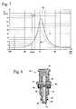
- Fig. 8 shows an example of a possible construction of a decompression valve 22.
- the decompression valve 22 has a holder 55 which forms a housing and in which a closing element 46 is arranged.
- the closing element 46 is formed bolt-shaped in the embodiment and has a closing portion 54 which cooperates in the closed state of the decompression valve 22 with a valve seat 45 formed on the holder 45.
- open position of the decompression valve air from the combustion chamber 29 on the outer circumference of the closing element 46 along an opening formed in the holder 55 opening 47 in a pressure relief space, for example in the environment escape. If the air to escape into the environment, the opening 47 is open to the outside.
- the pressure relief space for example, the interior of the crankcase 28 may be. If the air to escape into the interior of the crankcase 28, so the decompression valve 22 via an in Fig. 3 schematically drawn connecting line 56 may be connected to the interior of the crankcase 28.
- the closure member 46 is connected to an actuation button 49 which is to be pressed by the operator to open the decompression valve 22.
- a spring 48 is compressed and latching balls 50 engage in a latching recess 51 of the closing element 46 a.
- a pressure surface 57 is formed, on which the combustion pressure acts. If the combustion pressure is sufficiently high, the force acting on the pressure surface 57 is sufficient to move the detent balls 50 out of the detent recess 51 and to deflect them against the force exerted by a spring element 58 acting on the detent balls 50. This is done with the assistance of the force of the spring 48.
- the decompression valve 22 must be designed so that the closing element 46 securely engages in the open position and that after starting the engine 7, a safe closing of the decompression valve 22 is ensured.
- the combustion pressure in the combustion chamber 29 may be comparatively low after the starting process. This shows Fig. 5 .
- Fig. 5 are the first 50 engine cycles x after starting the engine 7, ie from the first combustion in the combustion chamber 29, shown.
- Fig. 5 shows the pressure p in the combustion chamber for the first 28 engine cycles x on the order of about 9 bar.
- the closing pressure p1 of the decompression valve 22 is somewhat higher in the exemplary embodiment, so that the decompression valve 22 remains open.
- the ignition timing ZZP is controlled based on the rotational speed n, namely on the basis of the idle control 44 (FIG. Fig. 4 ).
- the fact that the ignition timing ZZP is controlled on the basis of the rotational speed n results from the fact that the ignition timing ZZP in the lower diagram in FIG Fig. 5 is not constant but changes slightly from engine cycle to engine cycle. However, it is also possible to provide a constant ignition time ZZP, for example as dictated by the idling control 43.
- the ignition timing ZZP is changed from an ignition timing ZZP3 to a Sch Strukturzündzeittician ZZP2 after "early".
- the Sch conductedzündzeittician ZZP2 is advantageously at least about 5 ° crankshaft angle a, preferably at least about 10 ° crankshaft angle a, in particular 20 ° crankshaft angle a before the earliest ignition ZZP1.
- the Sch facilezündzeittician ZZP2 is at most about 40 ° crankshaft angle before the earliest ignition ZZP1.
- the Sch thoroughlyzündzeittician ZZP2 is 30 ° to 35 ° crankshaft angle, in particular about 33 ° crankshaft angle before the ignition ZZP3.
- the pressure p in the combustion chamber 29 rises to more than 15 bar, ie to a pressure significantly above the closing pressure p1 of the decompression valve 22.
- the decompression valve 22 is closed.
- the subsequent engine cycle x2 which corresponds to the 31st engine cycle in the embodiment, the ignition takes place again for Sch responsiblezündzeittician ZZP2.
- the pressure p established in the combustion chamber 29 is lower than that of the engine cycle x1, it is significantly higher than the closing pressure p1 of the decompression valve.
- the decompression valve 22 is now closed. From the subsequent engine cycle x, which is the 32nd engine cycle in the exemplary embodiment, the ignition takes place again to an ignition point ZZP determined on the basis of the idling control 44.
- the pressure p in the combustion chamber 29 after closing the decompression valve 22 is slightly higher than before the closing of the decompression valve 22 and is usually above the closing pressure p1. Since combustion does not have to take place at each engine cycle during idling, the ignition at the closing time ZZP2 during more than one engine cycle can ensure that combustion took place in at least one engine cycle in which ignition ZZP2 was initiated.
- the Schoughzündzeittician ZZP2 may be a fixed, stored in the controller 24 value. However, it can also be provided that the ignition time ZZP ascertained by means of the idling control 44 for this or a preceding engine cycle x is adjusted by a predetermined crankshaft angle ⁇ to "early", for example by about 30 ° to about 35 ° crankshaft angle a. At this time, the controller 24 may suspend the control of the ignition timing ZZP after the idling control 44 for the at least one engine cycle x1, x2 at which the closing timing ZZP2 is set. However, the controller 24 may also override the ignition timing ZZP provided after the idle control 44 by firing the ignition timing ZZP at the earlier time and for triggering a spark at the later time provided by the idle controller 44, insufficient energy to trigger a spark is available.
- the Schörzündzeittician ZZP2 is set for two engine cycles.
- the two engine cycles take place during the first 100 engine cycles, in particular during the first 50 engine cycles after the starting process.
- Fig. 6 shows the pressure curve of the pressure p in the combustion chamber 29 in the engine cycle 29.
- a line 41 indicates schematically the ignition timing.
- the pressure p which is drawn with a line 59, after triggering the spark at about 9 bar.
- the ignition takes place at the ignition time ZZP3, which is at about 10 ° to about 20 °, in particular at approximately 15 ° before the top dead center of the piston 15.
- Dashed line is in Fig. 6 a compression curve 60 without ignition, a so-called drag curve drawn.
- Fig. 7 the pressure curve in the combustion chamber 29 is indicated by a line 61 in the engine cycle x1 following the 29th engine cycle.
- the ignition timing ZZP which is shown schematically by a line 42, lies at Sch tozündzeittician ZZP2.
- the Sch thoroughlyzündzeittician ZZP2 is much earlier than the earliest ignition ZZP1 after the idle control 39 and is in the exemplary embodiment at about 47 ° before the top dead center of the piston 15. Due to the very early Zündzeithuis occurs strong combustion, and the pressure in the combustion chamber 29 increases to a Value of over 15 bar. Since the pressure p is significantly above the closing pressure p1 of the decompression valve 22, the decompression valve 22 is closed. Also in Fig. 7 the comparison curve 60 is located.
- Fig. 9 shows an embodiment of the method in which the ignition at two engine cycles x3 and x4 before the engine cycles x1 and x2, at which the ignition is moved to the Sch thoroughlyzündzeittician ZZP2 suspended. This ensures that the engine chamber x1 of the combustion chamber 29 is well rinsed and given a favorable mixture composition in the combustion chamber 29, so that combustion in the combustion chamber 29 can take place.
- Fig. 10 shows a flowchart of an alternative method for operating the internal combustion engine 7.
- the ignition timing ZZP is set in step 62 based on the idle control 43 or the idle control 44.
- method step 63 it is checked whether the engine cycle x1 has already been reached. If the engine cycle x1 has not yet been reached, the ignition time ZZP is furthermore controlled in method step 62 on the basis of the idling control 43 or 44. After reaching the engine cycle x1, the ignition timing ZZP is adjusted to the Sch thoroughlyzündzeittician ZZP2. Subsequently, in method step 65 it is determined whether combustion has taken place in combustion chamber 29.
- the ignition ignition point ZZP is again set to the closing ignition point ZZP2 and it is checked whether there is combustion took place. As soon as a combustion has taken place, the ignition time ZZP is set again in method step 66 on the basis of the idle control systems 43 or 44.
Landscapes
- Engineering & Computer Science (AREA)
- Chemical & Material Sciences (AREA)
- Combustion & Propulsion (AREA)
- Mechanical Engineering (AREA)
- General Engineering & Computer Science (AREA)
- Signal Processing (AREA)
- Theoretical Computer Science (AREA)
- Electrical Control Of Ignition Timing (AREA)
- Ignition Installations For Internal Combustion Engines (AREA)
Description
- Die Erfindung betrifft ein Verfahren zum Betrieb eines Verbrennungsmotors der im Oberbegriff des Anspruchs 1 angegebenen Gattung.
- Aus der
DE 195 04 105 A1 ist ein Verbrennungsmotor bekannt, der eine Dekompressionseinrichtung aufweist. Diese bekannte Dekompressionseinrichtung wird beim Betätigen eines Seilzugstarters automatisch ausgelöst und dabei das Dekompressionsventil geöffnet. Das Dekompressionsventil schließt sich aufgrund des im Zylinder bei einer Verbrennung entstehenden Verbrennungsdrucks. - Aus der
US 2003/056755 A1 ist ein Verfahren bekannt, welches ein Zurückschlagen der Kurbelwelle eines Verbrennungsmotors beim Start und beim Leerlauf vermeiden soll. Dabei wird der Zündzeitpunkt, der über eine Zündzeitpunktkurve gesteuert ist, geändert. - Die Zündung von Verbrennungsmotoren wird üblicherweise von einer Steuereinrichtung gesteuert. In einem Leerlaufdrehzahlbereich erfolgt die Zündung zu einem vergleichsweise späten Zündzeitpunkt. Im Leerlauf soll dadurch erreicht werden, dass die Drehzahl nicht übermäßig ansteigt, so dass sich eine konstante Leerlaufdrehzahl und nur geringe Drehzahlschwankungen im Leerlauf ergeben. Es hat sich allerdings gezeigt, dass bei bekannten Dekompressionsventilen der Verbrennungsdruck, der aufgrund des späten Zündzeitpunkts herrscht, nicht immer zuverlässig ausreicht, um das Dekompressionsventil zu schließen. Um sicherzustellen, dass das Dekompressionsventil von dem Verbrennungsdruck im Leerlauf zuverlässig geschlossen wird, müssen enge Toleranzen am Dekompressionsventil eingehalten werden, die zu einer aufwändigeren Herstellung des Dekompressionsventils führen.
- Der Erfindung liegt die Aufgabe zugrunde, ein Verfahren zum Betrieb eines Verbrennungsmotors zu schaffen, mit dem auch ein einfach aufgebautes Dekompressionsventil zuverlässig geschlossen werden kann.
- Diese Aufgabe wird durch ein Verfahren zum Betrieb eines Verbrennungsmotors mit den Merkmalen des Anspruchs 1 gelöst.
- Um ein sicheres Schließen des Dekompressionsventils zu erreichen, ist vorgesehen, dass für mindestens einen Motorzyklus die Zündung zu einem Schließzündzeitpunkt erfolgt, der etwa 5° Kurbelwellenwinkel vor dem frühesten Zündzeitpunkt liegt, insbesondere mindestens etwa 5° Kurbelwellenwinkel vor dem frühesten Zündzeitpunkt liegt. Der früheste Zündzeitpunkt ist dabei der früheste nach der Leerlaufsteuerung des Zündzeitpunkts vorgesehene Zündzeitpunkt. Die Zündung wird demnach im Leerlaufdrehzahlbereich für mindestens einen Motorzyklus nach "früh" verstellt. Dabei kann eine Frühverstellung des Zündzeitpunkts für einen einzigen Motorzyklus ausreichend sein. Es kann jedoch auch vorgesehen sein, den Zündzeitpunkt für mehrere Motorzyklen, insbesondere für mehrere aufeinander folgende Motorzyklen nach "früh" zu verstellen, um sicherzustellen, dass mindestens eine ausreichend starke Verbrennung erfolgt, die zu einem sicheren Schließen des Dekompressionsventils führt. Die Leerlaufsteuerung kann einen vergleichsweise späten Zündzeitpunkt vorsehen, der sicherstellt, dass sich ein ruhiger Lauf des Motors im Leerlaufdrehzahlbereich ergibt und der ein Zurückschlagen des Motors, also einen Antrieb des Motors in Gegendrehrichtung, sicher verhindert. Der nach der Leerlaufsteuerung vorgesehene Zündzeitpunkt muss nicht auf den Schließdruck des Dekompressionsventils abgestimmt sein. In dem mindestens einen Motorzyklus, in dem die Zündung zu dem Schließzündzeitpunkt erfolgt, findet eine stärkere Verbrennung im Brennraum statt. Dadurch wird ein höherer Druck im Brennraum erreicht, der zu einem sicheren Schließen des Dekompressionsventils führt. Ein übermäßig aufwändiger Aufbau des Dekompressionsventils oder eine übermäßig genaue Fertigung des Dekompressionsventils ist dadurch nicht notwendig.
- Das erfindungsgemäße Verfahren kann bei jedem Typ von Verbrennungsmotor mit einem Dekompressionsventil verwendet werden, z. B. bei einem konventionellen Verbrennungsmotor mit einem mechanischen Vergaser, bei einem Verbrennungsmotor mit elektronisch zuzumessender Kraftstoffmenge oder dgl. Motor. Insbesondere wird das erfindungsgemäße Verfahren angewendet bei Zweitaktmotoren mit Seilzugstarter oder elektrischem Starter.
- Der Schließzündzeitpunkt liegt vorteilhaft um höchstens etwa 40° Kurbelwellenwinkel vor dem frühesten Zündzeitpunkt. Dadurch kann ein Rückschlag des Motors noch sicher vermieden werden. Der Schließzündzeitpunkt liegt vorteilhaft mindestens etwa 10° Kurbelwellenwinkel, insbesondere etwa 20° Kurbelwellenwinkel vor dem frühesten Zündzeitpunkt. Dadurch wird ein ausreichend hoher Verbrennungsdruck im Brennraum erreicht, so dass das Dekompressionsventil sicher schließt. Vorteilhaft wird der Zündzeitpunkt anhand der Leerlaufsteuerung auf 0° bis etwa 20° Kurbelwellenwinkel vor dem oberen Totpunkt bestimmt und der Schließzündzeitpunkt liegt etwa 25° bis etwa 50° Kurbelwellenwinkel vor dem oberen Totpunkt.
- Der mindestens eine Motorzyklus, in dem die Zündung zum Schließzündzeitpunkt erfolgt, findet vorteilhaft während der ersten 100 Motorzyklen, insbesondere während der ersten 50 Motorzyklen nach dem Startvorgang statt. Mit dem Startvorgang ist dabei der Anwerfvorgang des Verbrennungsmotors bis zum Stattfinden der ersten Verbrennung im Brennraum gemeint. Nach der ersten Verbrennung wird der Verbrennungsmotor im Leerlauf betrieben, bis eine Beschleunigung aus dem Leerlaufdrehzahlbereich erfolgt.
- Um sicherzustellen, dass zu dem mindestens einen Motorzyklus, in dem die Zündung zum Schließzündzeitpunkt erfolgt, eine starke Verbrennung stattfindet, ist vorteilhaft vorgesehen, dass diesem Motorzyklus mindestens ein Motorzyklus vorausgeht, zu dem keine Zündung erfolgt. Insbesondere gehen dem mindestens einen Motorzyklus, zu dem die Zündung zum Schließzündzeitpunkt erfolgt, mehrere Motorzyklen ohne Zündung voraus. Vorteilhaft wird der Verbrennungsmotor so lange zu dem Schließzündzeitpunkt gezündet, bis eine Verbrennung im Brennraum stattgefunden hat. Dadurch ist sichergestellt, dass das Dekompressionsventil geschlossen ist. Hierzu ist vorgesehen, dass ermittelt wird, ob nach einem Motorzyklus, in dem die Zündung zum Schließzündzeitpunkt erfolgt ist, eine Verbrennung im Brennraum erfolgt ist. Falls keine Verbrennung erkannt wurde, ist vorgesehen, dass die Zündung im nächsten Motorzyklus erneut zum Schließzündzeitpunkt erfolgt. Die Ermittlung, ob eine Verbrennung erfolgt ist, kann auf einfache Weise dadurch erfolgen, dass die Drehzahl der Kurbelwelle überwacht wird. Steigt die Drehzahl beim Abwärtshub des Kolbens stärker an, übersteigt also die Beschleunigung einen Grenzwert, so fand eine Verbrennung statt. Es kann jedoch auch vorgesehen sein, die Ermittlung, ob eine Verbrennung stattgefunden hat, über einen Drucksensor im Brennraum vorzunehmen. Es kann auch vorgesehen sein, zu überwachen, ob das Dekompressionsventil geschlossen ist und die Zündung zum Schließzündzeitpunkt so lange vorzunehmen, bis das Dekompressionsventil sich geschlossen hat.
- Der Schließzündzeitpunkt kann ein fester, in der Steuereinrichtung abgespeicherter Zündzeitpunkt sein. Es kann jedoch auch vorgesehen sein, dass der Schließzündzeitpunkt ausgehend von einem nach der Leerlaufsteuerung vorgesehenen Zündzeitpunkt ermittelt wird. Beispielsweise kann der nach der Leerlaufsteuerung vorgesehene Zündzeitpunkt um eine in der Steuereinrichtung vorgegebene Anzahl von Winkelgraden Kurbelwellenwinkel nach "früh" verstellt werden. Der nach der Leerlaufsteuerung vorgesehene Zündzeitpunkt kann dabei der Zündzeitpunkt für den folgenden Motorzyklus oder ein Zündzeitpunkt eines vorangegangenen Motorzyklus sein. Die Steuereinrichtung kann vorsehen, die Leerlaufsteuerung zu dem oder den Motorzyklen, zu denen die Zündung zum Schließzündzeitpunkt erfolgt, auszusetzen. Die Steuereinrichtung nach der Leerlaufsteuerung kann jedoch auch übersteuert oder der vorgesehene Zündzeitpunkt auf einen früheren Zündzeitpunkt verschoben werden.
- Die Leerlaufsteuerung steuert den Zündzeitpunkt vorteilhaft in Abhängigkeit der Drehzahl des Verbrennungsmotors. Dabei ist insbesondere vorgesehen, dass der Zündzeitpunkt bei steigender Drehzahl nach "spät" verstellt wird. Dadurch wird ein ruhiger Lauf des Verbrennungsmotors im Leerlauf mit geringen Drehzahlschwankungen erreicht. Es kann jedoch auch vorgesehen sein, dass die Leerlaufsteuerung den Zündzeitpunkt auf einen konstanten Zündzeitpunkt festlegt. Das Dekompressionsventil öffnet in einen Druckentlastungsraum. Der Druckentlastungsraum ist insbesondere die Umgebung oder der Innenraum eines Kurbelgehäuses des Verbrennungsmotors.
- Ausführungsbeispiele der Erfindung werden im Folgenden anhand der Zeichnung erläutert. Es zeigen:
- Fig. 1
- eine Seitenansicht eines Trennschleifers,
- Fig. 2
- eine schematische Darstellung des Aufbaus des Antriebs des Trennschleifers aus
Fig. 1 , - Fig. 3
- einen schematischen Schnitt durch den Verbrennungsmotor des Trennschleifers aus
Fig. 1 , - Fig. 4
- ein schematisches Diagramm, das den Zündzeitpunkt in Abhängigkeit der Drehzahl angibt,
- Fig. 5
- ein Diagramm, das den maximalen Druck im Brennraum und den Zündzeitpunkt für die ersten 50 Motorzyklen angibt,
- Fig. 6
- ein Diagramm, das den Verlauf des Brennraumdrucks und den Zündzeitpunkt für den 29. Motorzyklus aus
Fig. 5 angibt, - Fig. 7
- ein Diagramm, das den Verlauf des Brennraumdrucks und den Zündzeitpunkt für den 30. Motorzyklus des Diagramms aus
Fig. 5 angibt, - Fig. 8
- einen Schnitt durch ein Dekompressionsventil,
- Fig. 9
- ein Diagramm, das den maximalen Druck im Brennraum und den Zündzeitpunkt für die ersten 50 Motorzyklen für ein weiteres Ausführungsbeispiel an gibt,
- Fig. 10
- ein Ablaufdiagramm, das den Ablauf des Verfahrens zeigt.
-
Fig. 1 zeigt als Ausführungsbeispiel für ein tragbares, handgeführtes Arbeitsgerät einen Trennschleifer 1. Das im Nachfolgenden noch näher beschriebene Verfahren zum Betrieb eines Verbrennungsmotors kann auch bei Verbrennungsmotoren für andere Einsatzgebiete, insbesondere bei Verbrennungsmotoren in anderen Arbeitsgeräten wie beispielsweise Motorsägen, Freischneidern, Blasgeräten, Sprühgeräten, Erntegeräten, Rasenmähern oder dergleichen eingesetzt werden. Der Trennschleifer 1 besitzt ein Gehäuse 2, an dem zwei Handgriffe zum Führen des Trennschleifers 1 im Betrieb, nämlich ein hinterer Handgriff 3 und ein Griffrohr 6 festgelegt sind. Am hinteren Handgriff 3 sind ein Gashebel 4 und eine Gashebelsperre 5 schwenkbar gelagert. An der dem hinteren Handgriff 3 abgewandt liegenden Seite des Gehäuses 2 ragt ein Ausleger 8 nach vorn, an dessen freiem Ende eine Trennscheibe 9 drehbar gelagert ist. Die Trennscheibe 9 ist über einen Teil ihres Umfangs von einer Schutzhaube 12 abgedeckt. Im Gehäuse 2 ist ein inFig. 2 gezeigter Verbrennungsmotor 7 angeordnet. Die Trennscheibe 9 ist vom Verbrennungsmotor 7 rotierend angetrieben. Zum Starten des Verbrennungsmotors 7 dient eine inFig. 2 schematisch gezeigte Anwerfvorrichtung 10, die einen Anwerfgriff 11 besitzt. WieFig. 1 zeigt, ragt der Anwerfgriff 11 aus dem Gehäuse 2 des Trennschleifers 1. - Der Verbrennungsmotor 7, der in
Fig. 2 schematisch gezeigt ist, ist vorteilhaft ein Einzylindermotor, insbesondere ein gemischgeschmierter Motor, vorzugsweise ein Zweitaktmotor. Der Verbrennungsmotor 7 besitzt einen Kolben 15, der über ein Pleuel 16 eine Kurbelwelle 17 um eine Drehachse 18 rotierend antreibt. An der Kurbelwelle 17 ist ein Schwungrad 19 festgelegt. Das Schwungrad 19 kann als Lüfterrad ausgebildet sein und Lüfterflügel zur Förderung von Kühlluft für den Verbrennungsmotor 7 besitzen. An der dem Schwungrad abgewandt liegenden Seite des Verbrennungsmotors 7 ist an der Kurbelwelle 17 eine Fliehkraftkupplung 20 festgelegt. Die Fliehkraftkupplung 20 besitzt mit der Kurbelwelle 17 drehfest verbundene, nicht gezeigte Fliehgewichte, die mit einer Kupplungstrommel 21 zusammenwirken. Die Kupplungstrommel 21 ist mit einer Antriebsscheibe 13 drehfest verbunden, an der ein Antriebsriemen 14 angeordnet ist. Der Antriebsriemen 14 verläuft im Ausleger 8 und treibt die Trennscheibe 9 an. WieFig. 2 zeigt, ist die Anwerfvorrichtung 10 benachbart zur Antriebsscheibe 13 am Ausleger 8 angeordnet und wirkt auf die Kurbelwelle 16. -
Fig. 3 zeigt den Aufbau des Verbrennungsmotors 7 im Einzelnen. Der Verbrennungsmotor 7 besitzt einen Zylinder 27, in den ein Dekompressionsventil 22 und eine Zündkerze 23 ragen. Die Ansteuerung der Zündkerze 23 erfolgt über eine Steuereinrichtung 24. Die Steuereinrichtung 24 steuert auch ein Kraftstoffventil 25, das im Ausführungsbeispiel an einem Kurbelgehäuse 28 des Verbrennungsmotors 7 angeordnet ist. Das Kraftstoffventil 25 führt Kraftstoff unter niedrigem Druck in den Innenraum des Kurbelgehäuses 28 zu. Der Innenraum des Kurbelgehäuses 28 ist über einen Überströmkanal 34 mit einem im Zylinder 27 ausgebildeten Brennraum 29 verbunden. Der Überströmkanal 34 teilt sich in mehrere, im Ausführungsbeispiel in vier Äste, die jeweils in einem Überströmfenster 35 in den Brennraum 29 münden. Auch eine andere Anzahl oder Gestaltung von einem oder mehreren Überströmkanälen 34 kann vorteilhaft sein. - Die Überströmfenster 35 sind von dem in
Fig. 3 schematisch gezeigten Kolben 15 gesteuert. An der Zylinderbohrung mündet ein Ansaugkanal 32 mit einem ebenfalls vom Kolben 15 gesteuerten Einlass 30 ins Kurbelgehäuse 28. Der Ansaugkanal 32 ist im Bereich des oberen Totpunkts des Kolbens 15 mit dem Innenraum des Kurbelgehäuses 28 verbunden. Im Ansaugkanal 32 ist ein Drosselelement 31 angeordnet, das im Ausführungsbeispiel als schwenkbar gelagerte Drosselklappe ausgebildet ist. Aus dem Brennraum 29 führt ein ebenfalls vom Kolben 15 gesteuerter Auslass 33, an den sich vorteilhaft ein nicht gezeigter Auslass anschließt. - Wie
Fig. 3 zeigt, ist das Kraftstoffventil 25 in einem Ventilhalter 26 angeordnet, der am Kurbelgehäuse 28 fixiert ist. Am Kurbelgehäuse 28 mündet außerdem eine Aufnahme 37 für weitere Bauteile. In der Aufnahme 37 kann beispielsweise eine Baueinheit aus Temperatursensor und Drucksensor angeordnet werden. Die Kurbelwelle 17 ist mit einem Lager 36 im Kurbelgehäuse 28 gelagert. Die Drehstellung der Kurbelwelle 17 wird über einen Kurbelwellenwinkel α beschrieben. Im oberen Totpunkt des Kolbens 15 beträgt der Kurbelwellenwinkel α 0° und in der inFig. 3 schematisch gezeigten Stellung im unteren Totpunkt des Kolbens 15 beträgt der Kurbelwellenwinkel α 180°. - Im Betrieb des Verbrennungsmotors 7 wird im Bereich des oberen Totpunkts des Kolbens 15, also bei einem Kurbelwellenwinkel a von 0°, Verbrennungsluft in den Innenraum des Kurbelgehäuses 28 angesaugt. Der Verbrennungsluft wird Kraftstoff über das Kraftstoffventil 25 zudosiert, der aufgrund der rotierenden Teile im Kurbelgehäuseinnenraum zerstäubt und mit der Verbrennungsluft zu Kraftstoff/Luft-Gemisch aufbereitet wird. Das Gemisch im Innenraum des Kurbelgehäuses 28 wird beim Abwärtshub des Kolbens 15, also bei der Bewegung des Kolbens 15 in Richtung auf das Kurbelgehäuse 28, komprimiert und, sobald die Überströmfenster 35 vom Kolben 15 geöffnet werden, in den Brennraum 29 gedrückt. Beim anschließenden Aufwärtshub des Kolbens 15, also bei der Bewegung des Kolbens 15 in Richtung auf den Brennraum 29, wird das Kraftstoff/LuftGemisch im Brennraum 29 komprimiert und im Bereich des oberen Totpunkts des Kolbens 15 von der Zündkerze 23 gezündet. Beim daran anschließenden Abwärtshub des Kolbens 15 wird der Auslass 33 geöffnet, und die Abgase entweichen aus dem Brennraum 29.
- Der Zündzeitpunkt ZZP wird in Abhängigkeit der Drehzahl n des Verbrennungsmotors 7 von der Steuereinrichtung 24 nach dem in
Fig. 4 schematisch gezeigten Diagramm gesteuert. Der Zündzeitpunkt ZZP ist dabei als Kurbelwellenwinkel α vor dem oberen Totpunkt des Kolbens 15 angegeben. Je weiter unten ein Zündzeitpunkt im Diagramm dargestellt ist, umso früher bezogen auf den oberen Totpunkt des Kolbens 15 findet die Zündung zu diesem Zündzeitpunkt statt. In einem Startdrehzahlbereich 38 wird der Zündzeitpunkt nach einer Linie 52 gesteuert. Bei steigender Drehzahl n wird der Zündzeitpunkt ZZP dabei nach "früh" verstellt. Der Startdrehzahlbereich 38 erstreckt sich im Ausführungsbeispiel bis etwa 2000 U/min. An den Startdrehzahlbereich schießt sich ein Leerlaufdrehzahlbereich 39 an. Der Leerlaufdrehzahlbereich 39 kann vorteilhaft im Drehzahlbereich von etwa 1500 U/min bis etwa 4000 U/min liegen. Der Leerlaufdrehzahlbereich 39 liegt unterhalb eines Einkuppeldrehzahlbereichs 40, in dem die Fliehkraftkupplung 20 beginnt einzukuppeln. Der Einkuppeldrehzahlbereich 40 kann sich im Bereich von etwa 3000 U/min bis etwa 6000 U/min erstrecken. Im Ausführungsbeispiel erstreckt sich der Leerlaufdrehzahlbereich 39 von etwa 2000 U/min bis etwa 3500 U/min und der Einkuppeldrehzahlbereich von etwa 4000 U/min bis etwa 5500 U/min. - Im Leerlaufdrehzahlbereich 39 wird der Zündzeitpunkt ZZP anhand einer Leerlaufsteuerung 43 gesteuert, die den Zündzeitpunkt ZZP auf einen festen, frühesten Zündzeitpunkt ZZP1 einstellt. Es kann jedoch auch vorgesehen sein, dass der Zündzeitpunkt ZZP im Leerlaufdrehzahlbereich 39 in Abhängigkeit der Drehzahl n gesteuert wird. Dabei ist insbesondere vorgesehen, dass der Zündzeitpunkt ZZP mit steigender Drehzahl n nach "spät" verstellt wird, wobei die Verstellung insbesondere linear erfolgt. Eine entsprechende Leerlaufsteuerung 44 ist in
Fig. 4 mit gestrichelter Linie eingezeichnet. - Der Startvorgang beginnt mit dem Beginn des Anwerfvorgangs, also wenn ein Bediener beginnt, am Anwerfgriff 11 zu ziehen, und endet mit der ersten Verbrennung im Brennraum 29. Bis zur ersten Verbrennung wird der Zündzeitpunkt ZZP anhand der Linie 52 gesteuert. Sinkt die Drehzahl n während des Betriebs aus dem Leerlaufdrehzahlbereich 39 bis in den Startdrehzahlbereich 38, also im Ausführungsbeispiel unter 2000 U/min, so wird der Zündzeitpunkt ZZP in Abhängigkeit der Linie 53 gesteuert. Dabei ist vorgesehen, den Zündzeitpunkt ZZP nach "früh" zu verstellen. Der nach der Linie 53 vorgesehene Zündzeitpunkt ZZP kann dabei auch vor dem frühesten Zündzeitpunkt ZZP1 liegen.
- Das Dekompressionsventil 22 dient dazu, den Kompressionsdruck beim Anwerfen des Verbrennungsmotors 7 zu verringern, so dass der Bediener weniger Kraft zum Ziehen des Anwerfgriffs 11 aufwenden muss. Das Dekompressionsventil 22 kann vom Bediener vor dem Starten des Verbrennungsmotors 7 von Hand zu öffnen sein. Es kann jedoch auch vorgesehen sein, dass das Dekompressionsventil 22 automatisch, beispielsweise vor oder beim Betätigen der Anwerfvorrichtung 10 in die geöffnete Stellung gestellt wird. Sobald im Brennraum 29 eine Verbrennung stattfindet, soll das Dekompressionsventil 22 aufgrund des Verbrennungsdrucks schließen.
-
Fig. 8 zeigt exemplarisch einen möglichen Aufbau eines Dekompressionsventils 22. Das Dekompressionsventil 22 besitzt einen Halter 55, der ein Gehäuse bildet und in dem ein Schließelement 46 angeordnet ist. Das Schließelement 46 ist im Ausführungsbeispiel bolzenförmig ausgebildet und besitzt einen Schließabschnitt 54, der im geschlossenen Zustand des Dekompressionsventils 22 mit einem an dem Halter 55 ausgebildeten Ventilsitz 45 zusammenwirkt. In der inFig. 8 gezeigten, geöffneten Stellung des Dekompressionsventils kann Luft aus dem Brennraum 29 am Außenumfang des Schließelements 46 entlang durch eine im Halter 55 ausgebildete Öffnung 47 in einen Druckentlastungsraum, beispielsweise in die Umgebung, entweichen. Soll die Luft in die Umgebung entweichen, so ist die Öffnung 47 nach außen offen. Der Druckentlastungsraum kann beispielsweise auch der Innenraum des Kurbelgehäuses 28 sein. Soll die Luft in den Innenraum des Kurbelgehäuses 28 entweichen, so kann das Dekompressionsventil 22 über eine inFig. 3 schematisch eingezeichnete Verbindungsleitung 56 mit dem Innenraum des Kurbelgehäuses 28 verbunden sein. - Das Schließelement 46 ist mit einem Betätigungsknopf 49 verbunden, der vom Bediener zum Öffnen des Dekompressionsventils 22 zu drücken ist. Dabei wird eine Feder 48 komprimiert und Rastkugeln 50 rasten in einer Rastvertiefung 51 des Schließelements 46 ein. An der Stirnseite des Schließelements 46 ist eine Druckfläche 57 gebildet, auf die der Verbrennungsdruck wirkt. Ist der Verbrennungsdruck ausreichend hoch, so reicht die auf die Druckfläche 57 wirkende Kraft aus, um die Rastkugeln 50 aus der Rastvertiefung 51 zu bewegen und entgegen der von einem die Rastkugeln 50 beaufschlagenden Federelement 58 ausgeübten Kraft auszulenken. Dies erfolgt mit Unterstützung der Kraft der Feder 48.
- Das Dekompressionsventil 22 muss so ausgelegt sein, dass das Schließelement 46 sicher in der geöffneten Stellung einrastet und dass nach dem Starten des Verbrennungsmotors 7 ein sicheres Schließen des Dekompressionsventils 22 gewährleistet wird. Je nach Verbrennungsmotor 7 kann der Verbrennungsdruck im Brennraum 29 nach dem Startvorgang vergleichsweise niedrig sein. Dies zeigt
Fig. 5 . InFig. 5 sind die ersten 50 Motorzyklen x nach dem Starten des Verbrennungsmotors 7, also ab der ersten Verbrennung im Brennraum 29, dargestellt. WieFig. 5 zeigt, liegt der Druck p im Brennraum für die ersten 28 Motorzyklen x in der Größenordnung von etwa 9 bar. Der Schließdruck p1 des Dekompressionsventils 22 liegt im Ausführungsbeispiel etwas höher, so dass das Dekompressionsventil 22 geöffnet bleibt. Der Zündzeitpunkt ZZP wird dabei anhand der Drehzahl n gesteuert, und zwar anhand der Leerlaufsteuerung 44 (Fig. 4 ). Dass der Zündzeitpunkt ZZP anhand der Drehzahl n gesteuert ist, ergibt sich daraus, dass der Zündzeitpunkt ZZP im unteren Diagramm inFig. 5 nicht konstant ist sondern sich von Motorzyklus zu Motorzyklus geringfügig ändert. Es kann jedoch auch ein konstanter Zündzeitpunkt ZZP vorgesehen sein, beispielsweise wie er durch die Leerlaufsteuerung 43 vorgegeben wird. - Zu einem Motorzyklus x1, der im Ausführungsbeispiel der 30. Motorzyklus nach dem Starten ist, wird der Zündzeitpunkt ZZP von einem Zündzeitpunkt ZZP3 auf einen Schließzündzeitpunkt ZZP2 nach "früh" verstellt. Der Schließzündzeitpunkt ZZP2 liegt vorteilhaft mindestens etwa 5° Kurbelwellenwinkel a, vorzugsweise mindestens etwa 10° Kurbelwellenwinkel a, insbesondere 20° Kurbelwellenwinkel a vor dem frühesten Zündzeitpunkt ZZP1. Der Schließzündzeitpunkt ZZP2 liegt dabei höchstens etwa 40° Kurbelwellenwinkel vor dem frühesten Zündzeitpunkt ZZP1. Im Ausführungsbeispiel liegt der Schließzündzeitpunkt ZZP2 um 30° bis 35° Kurbelwellenwinkel, insbesondere etwa 33° Kurbelwellenwinkel vor dem Zündzeitpunkt ZZP3. Wie
Fig. 5 im oberen Teil des Diagramms zeigt, steigt der Druck p im Brennraum 29 dadurch auf über 15 bar, also auf einen Druck deutlich über dem Schließdruck p1 des Dekompressionsventils 22, an. Dadurch wird das Dekompressionsventil 22 geschlossen. Auch im darauffolgenden Motorzyklus x2, der im Ausführungsbeispiel dem 31. Motorzyklus entspricht, erfolgt die Zündung nochmals zum Schließzündzeitpunkt ZZP2. Der sich im Brennraum 29 einstellende Druck p ist zwar niedriger als der zum Motorzyklus x1, jedoch deutlich höher als der Schließdruck p1 des Dekompressionsventils. Das Dekompressionsventil 22 ist nun geschlossen. Ab dem darauffolgenden Motorzyklus x, der im Ausführungsbeispiel der 32. Motorzyklus ist, erfolgt die Zündung wieder zu einem anhand der Leerlaufsteuerung 44 ermittelten Zündzeitpunkt ZZP. WieFig. 5 auch zeigt, ist der Druck p im Brennraum 29 nach Schließen des Dekompressionsventils 22 geringfügig höher als vor dem Schließen des Dekompressionsventils 22 und liegt meist oberhalb des Schließdrucks p1. Da im Leerlauf nicht bei jedem Motorzyklus eine Verbrennung stattfinden muss, kann durch das Zünden zum Schließzeitpunkt ZZP2 bei mehr als einem Motorzyklus sichergestellt werden, dass bei mindestens einem Motorzyklus, in dem zum Schließzündzeitpunkt ZZP2 gezündet wurde, eine Verbrennung stattfand. - Der Schließzündzeitpunkt ZZP2 kann ein fester, in der Steuereinrichtung 24 hinterlegter Wert sein. Es kann jedoch auch vorgesehen sein, dass der anhand der Leerlaufsteuerung 44 für diesen oder einen vorangegangenen Motorzyklus x ermittelte Zündzeitpunkt ZZP um einen vorgegebenen Kurbelwellenwinkel α nach "früh" verstellt wird, beispielsweise um etwa 30° bis etwa 35° Kurbelwellenwinkel a. Dabei kann die Steuereinrichtung 24 die Steuerung des Zündzeitpunkts ZZP nach der Leerlaufsteuerung 44 für den mindestens einen Motorzyklus x1, x2, zu dem der Schließzeitpunkt ZZP2 eingestellt wird, aussetzen. Die Steuereinrichtung 24 kann den nach der Leerlaufsteuerung 44 vorgesehenen Zündzeitpunkt ZZP jedoch auch übersteuern, indem der Zündzeitpunkt ZZP zu dem früheren Zeitpunkt ausgelöst wird und für die Auslösung eines Zündfunkens zu dem von der Leerlaufsteuerung 44 vorgesehenen, späteren Zeitpunkt nicht mehr ausreichend Energie zur Auslösung eines Zündfunkens zur Verfügung steht.
- Im Ausführungsbeispiel nach
Fig. 5 ist vorgesehen, dass der Schließzündzeitpunkt ZZP2 für zwei Motorzyklen eingestellt wird. Die beiden Motorzyklen finden dabei während der ersten 100 Motorzyklen, insbesondere während der ersten 50 Motorzyklen nach dem Startvorgang statt. -
Fig. 6 zeigt den Druckverlauf des Drucks p im Brennraum 29 beim Motorzyklus 29. Eine Linie 41 gibt schematisch den Zündzeitpunkt an. WieFig. 6 zeigt, steigt der Druck p, der mit einer Linie 59 eingezeichnet ist, nach dem Auslösen des Zündfunkens auf etwa 9 bar an. Die Zündung erfolgt zum Zündzeitpunkt ZZP3, der bei etwa 10° bis etwa 20°, insbesondere bei näherungsweise 15° vor dem oberen Totpunkt des Kolbens 15 liegt. Mit gestrichelter Linie ist inFig. 6 eine Kompressionskurve 60 ohne Zündung, eine sogenannte Schleppkurve eingezeichnet. - In
Fig. 7 ist der Druckverlauf im Brennraum 29 beim auf den 29. Motorzyklus folgenden Motorzyklus x1 mit einer Linie 61 eingezeichnet. Der Zündzeitpunkt ZZP, der schematisch mit einer Linie 42 dargestellt ist, liegt beim Schließzündzeitpunkt ZZP2. Der Schließzündzeitpunkt ZZP2 liegt deutlich früher als der früheste Zündzeitpunkt ZZP1 nach der Leerlaufsteuerung 39 und liegt im Ausführungsbeispiel bei etwa 47° vor dem oberen Totpunkt des Kolbens 15. Aufgrund des sehr frühen Zündzeitpunkts erfolgt eine starke Verbrennung, und der Druck im Brennraum 29 steigt auf einen Wert von über 15 bar an. Da der Druck p deutlich über dem Schließdruck p1 des Dekompressionsventils 22 liegt, wird das Dekompressionsventil 22 geschlossen. Auch inFig. 7 ist die Vergleichskurve 60 eingezeichnet. -
Fig. 9 zeigt ein Ausführungsbeispiel des Verfahrens, bei dem die Zündung bei zwei Motorzyklen x3 und x4 vor den Motorzyklen x1 und x2, zu denen die Zündung auf den Schließzündzeitpunkt ZZP2 verstellt wird, ausgesetzt wird. Dadurch wird sichergestellt, dass zum Motorzyklus x1 der Brennraum 29 gut gespült ist und eine günstige Gemischzusammensetzung im Brennraum 29 gegeben ist, so dass eine Verbrennung im Brennraum 29 erfolgen kann. -
Fig. 10 zeigt ein Ablaufdiagramm eines alternativen Verfahrens zum Betrieb des Verbrennungsmotors 7. Der Zündzeitpunkt ZZP wird im Verfahrensschritt 62 anhand der Leerlaufsteuerung 43 oder anhand der Leerlaufsteuerung 44 eingestellt. Im Verfahrensschritt 63 wird überprüft, ob der Motorzyklus x1 bereits erreicht ist. Ist der Motorzyklus x1 noch nicht erreicht, so wird der Zündzeitpunkt ZZP weiterhin im Verfahrensschritt 62 anhand der Leerlaufsteuerung 43 oder 44 gesteuert. Nach Erreichen des Motorzyklus x1 wird der Zündzeitpunkt ZZP auf den Schließzündzeitpunkt ZZP2 verstellt. Anschließend wird im Verfahrensschritt 65 ermittelt, ob eine Verbrennung im Brennraum 29 stattgefunden hat. Dies kann beispielsweise durch Ermittlung der Beschleunigung der Kurbelwelle 17 anhand der Drehzahl n der Kurbelwelle 17 oder durch Ermittlung des Drucks p im Brennraum 29 erfolgen. Hat keine Verbrennung stattgefunden, so wird als Zündzeitpunkt ZZP erneut der Schließzündzeitpunkt ZZP2 eingestellt und überprüft, ob nun eine Verbrennung stattgefunden hat. Sobald eine Verbrennung stattgefunden hat, wird der Zündzeitpunkt ZZP im Verfahrensschritt 66 wieder anhand der Leerlaufsteuerungen 43 oder 44 eingestellt.
Claims (13)
- Verfahren zum Betrieb eines Verbrennungsmotors, wobei der Verbrennungsmotor (7) einen Zylinder (27) besitzt, in dem ein Kolben (15) hin- und hergehend gelagert ist, der eine in einem Kurbelgehäuse (28) drehbar gelagerte Kurbelwelle (17) antreibt, wobei der Kolben (15) einen Brennraum (29) begrenzt, wobei in den Brennraum (29) eine Zündkerze (23) ragt, mit einer Anwerfvorrichtung (10) zum Starten des Verbrennungsmotors (7), wobei die Zündung der Zündkerze (23) zu einem Zündzeitpunkt (ZZP) erfolgt, der von einer Steuereinrichtung (24) gesteuert wird, wobei der Zündzeitpunkt (ZZP) in einem Leerlaufdrehzahlbereich (39) nach einer Leerlaufsteuerung (43, 44) gesteuert wird, die einen frühesten Zündzeitpunkt (ZZP1) besitzt, wobei der Verbrennungsmotor (7) ein Dekompressionsventil (22) besitzt, das in geöffnetem Zustand den Brennraum (29) mit einem Druckentlastungsraum verbindet, wobei das Dekompressionsventil (22) beim Starten des Verbrennungsmotors (7) geöffnet ist und wobei das Dekompressionsventil (22) schließt, wenn der Druck (p) im Brennraum (29) einen Schließdruck (p1) überschreitet,
dadurch gekennzeichnet, dass die Zündung im Leerlaufdrehzahlbereich (39) für mindestens einen Motorzyklus (x1, x2) abweichend von der Leerlaufsteuerung (43,44) zu einem Schließzündzeitpunkt (ZZP2) erfolgt, der mindestens etwa 5° Kurbelwellenwinkel (a) vor dem frühesten Zündzeitpunkt (ZZP1) liegt, so dass ein höherer Druck im Brennraum (29) erreicht wird, der zu einem sicheren Schließen des Dekompressionsventils (22) führt. - Verfahren nach Anspruch 1,
dadurch gekennzeichnet, dass der Schließzündzeitpunkt (ZZP2) um höchstens etwa 40° Kurbelwellenwinkel (α) vor dem frühesten Zündzeitpunkt (ZZP1) liegt. - Verfahren nach Anspruch 1 oder 2,
dadurch gekennzeichnet, dass der Schließzündzeitpunkt (ZZP2) mindestens etwa 20° Kurbelwellenwinkel (α) vor dem frühesten Zündzeitpunkt (ZZP1) liegt. - Verfahren nach einem der Ansprüche 1 bis 3,
dadurch gekennzeichnet, dass der Zündzeitpunkt (ZZP) anhand der Leerlaufsteuerung (43, 44) auf 0° bis etwa 20° Kurbelwellenwinkel (α) vor dem oberen Totpunkt bestimmt wird. - Verfahren nach einem der Ansprüche 1 bis 4,
dadurch gekennzeichnet, dass der Schließzündzeitpunkt (ZZP2) etwa 25° bis etwa 50° Kurbelwellenwinkel (α) vor dem oberen Totpunkt liegt. - Verfahren nach einem der Ansprüche 1 bis 5,
dadurch gekennzeichnet, dass der mindestens eine Motorzyklus (x1, x2), in dem die Zündung zum Schließzündzeitpunkt (ZZP2) erfolgt, während der ersten 100 Motorzyklen (x), insbesondere während der ersten 50 Motorzyklen (x) nach dem Startvorgang stattfindet. - Verfahren nach einem der Ansprüche 1 bis 6,
dadurch gekennzeichnet, dass dem mindestens einen Motorzyklus (x1, x2), in dem die Zündung zum Schließzündzeitpunkt (ZZP2) erfolgt, mindestens ein Motorzyklus (x3, x4) vorausgeht, zu dem keine Zündung erfolgt. - Verfahren nach einem der Ansprüche 1 bis 7,
dadurch gekennzeichnet, dass ermittelt wird, ob nach einem Motorzyklus (x1), in dem die Zündung zum Schließzündzeitpunkt (ZZP2) erfolgt ist, eine Verbrennung im Brennraum (29) erfolgt ist und, falls keine Verbrennung erkannt wird, die Zündung im nächsten Motorzyklus (x2) erneut zum Schließzündzeitpunkt (ZZP2) erfolgt. - Verfahren nach einem der Ansprüche 1 bis 8,
dadurch gekennzeichnet, dass der Schließzündzeitpunkt (ZZP2) ein fester, in der Steuereinrichtung abgespeicherter Zündzeitpunkt (ZZP) ist. - Verfahren nach einem der Ansprüche 1 bis 9,
dadurch gekennzeichnet, dass der Schließzündzeitpunkt (ZZP2) ausgehend von einem nach der Leerlaufsteuerung (43, 44) vorgesehenen Zündzeitpunkt (ZZP) ermittelt wird. - Verfahren nach einem der Ansprüche 1 bis 10,
dadurch gekennzeichnet, dass die Leerlaufsteuerung (43, 44) den Zündzeitpunkt (ZZP) in Abhängigkeit der Drehzahl (n) des Verbrennungsmotors (7) steuert. - Verfahren nach einem der Ansprüche 1 bis 11,
dadurch gekennzeichnet, dass die Leerlaufsteuerung (43, 44) den Zündzeitpunkt (ZZP) auf einen konstanten Zündzeitpunkt festlegt. - Verfahren nach einem der Ansprüche 1 bis 12,
dadurch gekennzeichnet, dass der Druckentlastungsraum die Umgebung oder der Innenraum des Kurbelgehäuses (28) ist.
Applications Claiming Priority (1)
| Application Number | Priority Date | Filing Date | Title |
|---|---|---|---|
| DE102013005807.4A DE102013005807A1 (de) | 2013-04-04 | 2013-04-04 | Verfahren zum Betrieb eines Verbrennungsmotors |
Publications (3)
| Publication Number | Publication Date |
|---|---|
| EP2787215A2 EP2787215A2 (de) | 2014-10-08 |
| EP2787215A3 EP2787215A3 (de) | 2017-05-17 |
| EP2787215B1 true EP2787215B1 (de) | 2019-10-23 |
Family
ID=50439117
Family Applications (1)
| Application Number | Title | Priority Date | Filing Date |
|---|---|---|---|
| EP14001227.9A Active EP2787215B1 (de) | 2013-04-04 | 2014-04-02 | Verfahren zum Betrieb eines Verbrennungsmotors |
Country Status (6)
| Country | Link |
|---|---|
| US (1) | US20140299098A1 (de) |
| EP (1) | EP2787215B1 (de) |
| CN (1) | CN104100388B (de) |
| BR (1) | BR102014007918B1 (de) |
| DE (1) | DE102013005807A1 (de) |
| RU (1) | RU2659653C2 (de) |
Families Citing this family (5)
| Publication number | Priority date | Publication date | Assignee | Title |
|---|---|---|---|---|
| DE102017115596A1 (de) * | 2017-07-12 | 2019-01-17 | Man Truck & Bus Ag | Verfahren zum Starten einer Brennkraftmaschine |
| DE102018002964A1 (de) | 2017-09-15 | 2019-03-21 | Andreas Stihl Ag & Co. Kg | Handgeführtes Arbeitsgerät |
| EP3456949B1 (de) * | 2017-09-15 | 2020-12-09 | Andreas Stihl AG & Co. KG | Handgeführtes arbeitsgerät |
| SE1850338A1 (en) | 2018-03-27 | 2019-09-28 | Husqvarna Ab | A cooling and air intake arrangement for a combustion engine |
| US12577929B2 (en) * | 2021-04-26 | 2026-03-17 | Yamabiko Corporation | Easy engine starting system |
Family Cites Families (15)
| Publication number | Priority date | Publication date | Assignee | Title |
|---|---|---|---|---|
| SU428105A1 (ru) * | 1971-02-25 | 1974-05-15 | Двигатель внутреннего сгорания | |
| EP0238996A3 (en) * | 1986-03-21 | 1988-12-14 | Roger Martin Hall | Two-stroke engine |
| JPH0765510B2 (ja) * | 1987-09-04 | 1995-07-19 | 三信工業株式会社 | 2サイクルエンジン |
| DE19504105A1 (de) | 1994-02-16 | 1995-08-17 | Dolmar Gmbh | Dekompressionseinrichtung |
| SE504202C2 (sv) * | 1995-04-07 | 1996-12-09 | Electrolux Ab | Cylinder till en förbränningsmotor av tvåtaktstyp |
| JP4382965B2 (ja) * | 2000-05-19 | 2009-12-16 | 本田技研工業株式会社 | 船舶推進機の始動時点火時期制御装置 |
| US6761148B2 (en) * | 2001-09-03 | 2004-07-13 | Prufrex-Electro-Apparateubau, Inh. Helga Muller, Geb Dutschke | Electronic rotation speed-dependent control and/or diagnosis process for combustion engines |
| DE10243167B4 (de) * | 2002-09-18 | 2013-01-17 | Andreas Stihl Ag & Co. | Verbrennungsmotor mit einem Vergaser und einer Starteinrichtung |
| JP4490846B2 (ja) * | 2005-02-21 | 2010-06-30 | 本田技研工業株式会社 | エンジンのデコンプ装置 |
| JP4317535B2 (ja) * | 2005-06-23 | 2009-08-19 | ヤマハ発動機株式会社 | ハイブリッド二輪車の駆動装置及びハイブリッド二輪車 |
| JP4535330B2 (ja) * | 2005-11-10 | 2010-09-01 | 本田技研工業株式会社 | エンジン制御装置 |
| DE202005020147U1 (de) * | 2005-12-22 | 2007-05-10 | Dolmar Gmbh | Startvorrichtung für Brennkraftmaschinen |
| JP5030851B2 (ja) * | 2008-04-23 | 2012-09-19 | 本田技研工業株式会社 | 車両用エンジンのファーストアイドル制御装置 |
| JP5446919B2 (ja) * | 2010-01-22 | 2014-03-19 | スズキ株式会社 | 4サイクルエンジンのデコンプ装置 |
| US8863726B2 (en) * | 2011-09-21 | 2014-10-21 | Jacobs Vehicle Systems, Inc. | Method and system for engine cylinder decompression |
-
2013
- 2013-04-04 DE DE102013005807.4A patent/DE102013005807A1/de not_active Withdrawn
-
2014
- 2014-04-02 BR BR102014007918-1A patent/BR102014007918B1/pt not_active IP Right Cessation
- 2014-04-02 RU RU2014112558A patent/RU2659653C2/ru active
- 2014-04-02 EP EP14001227.9A patent/EP2787215B1/de active Active
- 2014-04-04 CN CN201410134488.7A patent/CN104100388B/zh not_active Expired - Fee Related
- 2014-04-04 US US14/245,649 patent/US20140299098A1/en not_active Abandoned
Non-Patent Citations (1)
| Title |
|---|
| None * |
Also Published As
| Publication number | Publication date |
|---|---|
| RU2659653C2 (ru) | 2018-07-03 |
| BR102014007918A2 (pt) | 2015-07-14 |
| DE102013005807A1 (de) | 2014-10-09 |
| BR102014007918B1 (pt) | 2021-12-21 |
| CN104100388B (zh) | 2018-03-30 |
| RU2014112558A (ru) | 2015-10-10 |
| EP2787215A2 (de) | 2014-10-08 |
| CN104100388A (zh) | 2014-10-15 |
| EP2787215A3 (de) | 2017-05-17 |
| US20140299098A1 (en) | 2014-10-09 |
Similar Documents
| Publication | Publication Date | Title |
|---|---|---|
| EP2481905B1 (de) | Verfahren zur Steuerung der Drehzahlbegrenzung eines Verbrennungsmotors | |
| EP2891785B1 (de) | Verfahren zum betrieb eines handgeführten arbeitsgeräts mit einem verbrennungsmotor | |
| EP2787215B1 (de) | Verfahren zum Betrieb eines Verbrennungsmotors | |
| EP2746569B1 (de) | Verfahren zum Betrieb eines Verbrennungsmotors in einem handgeführten Arbeitsgerät | |
| DE102011103125B4 (de) | Verfahren zum Betrieb eines Arbeitsgeräts | |
| DE102014007878A1 (de) | Handgeführtes Arbeitsgerät | |
| EP2602470B1 (de) | Verbrennungsmotor mit einem Kraftstoffsystem | |
| DE102007031396A1 (de) | Verfahren zum Betrieb eines Zweitaktmotors | |
| DE102013009891A1 (de) | Arbeitsgerät mit einem Verbrennungsmotor | |
| DE102014119349A1 (de) | Motorbetriebenes arbeitswerkzeug | |
| DE102012015034A1 (de) | Verfahren zur Abschaltung einer Drehzahlbegrenzung bei einem Verbrennungsmotor | |
| DE102009040321A1 (de) | Verfahren zum Betrieb eines Verbrennungsmotors | |
| EP2679357B1 (de) | Arbeitsgerät | |
| WO2012119807A1 (de) | Motorarbeitsgerät mit einer verbrennungskraftmaschine | |
| EP2848800B1 (de) | Verfahren zum Starten eines Verbrennungsmotors mit einer Startvorrichtung | |
| DE102008064008B4 (de) | Verfahren zum Betrieb eines Verbrennungsmotors | |
| EP3561257B1 (de) | Verbrennungsmotor und verfahren zu dessen betrieb | |
| EP2270325B1 (de) | Verfahren zum Betrieb eines Verbrennungsmotors | |
| EP3144521B1 (de) | Verfahren zum betrieb eines arbeitsgerätes mit einem verbrennungsmotor | |
| EP3660285B1 (de) | Gemischgeschmierter viertaktmotor, handgeführtes arbeitsgerät mit einem viertaktmotor und verfahren zum betrieb eines gemischgeschmierten viertaktmotors | |
| DE102018002964A1 (de) | Handgeführtes Arbeitsgerät | |
| EP3456949B1 (de) | Handgeführtes arbeitsgerät | |
| EP4224007A1 (de) | Zündschaltung für einen verbrennungsmotor | |
| EP3992445B1 (de) | Verfahren zum betrieb eines zweitaktmotors | |
| DE102015001452A1 (de) | Vergaser und Verfahren zum Betrieb eines Verbrennungsmotors mit einem Vergaser |
Legal Events
| Date | Code | Title | Description |
|---|---|---|---|
| PUAI | Public reference made under article 153(3) epc to a published international application that has entered the european phase |
Free format text: ORIGINAL CODE: 0009012 |
|
| 17P | Request for examination filed |
Effective date: 20140402 |
|
| AK | Designated contracting states |
Kind code of ref document: A2 Designated state(s): AL AT BE BG CH CY CZ DE DK EE ES FI FR GB GR HR HU IE IS IT LI LT LU LV MC MK MT NL NO PL PT RO RS SE SI SK SM TR |
|
| AX | Request for extension of the european patent |
Extension state: BA ME |
|
| PUAL | Search report despatched |
Free format text: ORIGINAL CODE: 0009013 |
|
| AK | Designated contracting states |
Kind code of ref document: A3 Designated state(s): AL AT BE BG CH CY CZ DE DK EE ES FI FR GB GR HR HU IE IS IT LI LT LU LV MC MK MT NL NO PL PT RO RS SE SI SK SM TR |
|
| AX | Request for extension of the european patent |
Extension state: BA ME |
|
| RIC1 | Information provided on ipc code assigned before grant |
Ipc: F02D 13/02 20060101ALI20170412BHEP Ipc: F02P 5/15 20060101AFI20170412BHEP Ipc: F02N 3/02 20060101ALN20170412BHEP Ipc: F02D 35/02 20060101ALN20170412BHEP Ipc: F02D 41/14 20060101ALN20170412BHEP Ipc: F02N 19/00 20100101ALI20170412BHEP |
|
| STAA | Information on the status of an ep patent application or granted ep patent |
Free format text: STATUS: REQUEST FOR EXAMINATION WAS MADE |
|
| R17P | Request for examination filed (corrected) |
Effective date: 20171107 |
|
| RBV | Designated contracting states (corrected) |
Designated state(s): AL AT BE BG CH CY CZ DE DK EE ES FI FR GB GR HR HU IE IS IT LI LT LU LV MC MK MT NL NO PL PT RO RS SE SI SK SM TR |
|
| RIC1 | Information provided on ipc code assigned before grant |
Ipc: F02P 5/15 20060101AFI20190417BHEP Ipc: F02D 41/14 20060101ALN20190417BHEP Ipc: F02D 35/02 20060101ALN20190417BHEP Ipc: F02N 3/02 20060101ALN20190417BHEP Ipc: F02N 19/00 20100101ALI20190417BHEP Ipc: F02D 13/02 20060101ALI20190417BHEP |
|
| GRAP | Despatch of communication of intention to grant a patent |
Free format text: ORIGINAL CODE: EPIDOSNIGR1 |
|
| STAA | Information on the status of an ep patent application or granted ep patent |
Free format text: STATUS: GRANT OF PATENT IS INTENDED |
|
| INTG | Intention to grant announced |
Effective date: 20190527 |
|
| GRAS | Grant fee paid |
Free format text: ORIGINAL CODE: EPIDOSNIGR3 |
|
| GRAA | (expected) grant |
Free format text: ORIGINAL CODE: 0009210 |
|
| STAA | Information on the status of an ep patent application or granted ep patent |
Free format text: STATUS: THE PATENT HAS BEEN GRANTED |
|
| AK | Designated contracting states |
Kind code of ref document: B1 Designated state(s): AL AT BE BG CH CY CZ DE DK EE ES FI FR GB GR HR HU IE IS IT LI LT LU LV MC MK MT NL NO PL PT RO RS SE SI SK SM TR |
|
| REG | Reference to a national code |
Ref country code: GB Ref legal event code: FG4D Free format text: NOT ENGLISH |
|
| RIN1 | Information on inventor provided before grant (corrected) |
Inventor name: KLATT, CLEMENS Inventor name: RAFFENBERG, MICHAEL |
|
| REG | Reference to a national code |
Ref country code: CH Ref legal event code: EP |
|
| REG | Reference to a national code |
Ref country code: IE Ref legal event code: FG4D Free format text: LANGUAGE OF EP DOCUMENT: GERMAN |
|
| REG | Reference to a national code |
Ref country code: DE Ref legal event code: R096 Ref document number: 502014012886 Country of ref document: DE |
|
| REG | Reference to a national code |
Ref country code: AT Ref legal event code: REF Ref document number: 1193910 Country of ref document: AT Kind code of ref document: T Effective date: 20191115 |
|
| REG | Reference to a national code |
Ref country code: NL Ref legal event code: MP Effective date: 20191023 |
|
| REG | Reference to a national code |
Ref country code: LT Ref legal event code: MG4D |
|
| PG25 | Lapsed in a contracting state [announced via postgrant information from national office to epo] |
Ref country code: PT Free format text: LAPSE BECAUSE OF FAILURE TO SUBMIT A TRANSLATION OF THE DESCRIPTION OR TO PAY THE FEE WITHIN THE PRESCRIBED TIME-LIMIT Effective date: 20200224 Ref country code: ES Free format text: LAPSE BECAUSE OF FAILURE TO SUBMIT A TRANSLATION OF THE DESCRIPTION OR TO PAY THE FEE WITHIN THE PRESCRIBED TIME-LIMIT Effective date: 20191023 Ref country code: NO Free format text: LAPSE BECAUSE OF FAILURE TO SUBMIT A TRANSLATION OF THE DESCRIPTION OR TO PAY THE FEE WITHIN THE PRESCRIBED TIME-LIMIT Effective date: 20200123 Ref country code: LT Free format text: LAPSE BECAUSE OF FAILURE TO SUBMIT A TRANSLATION OF THE DESCRIPTION OR TO PAY THE FEE WITHIN THE PRESCRIBED TIME-LIMIT Effective date: 20191023 Ref country code: PL Free format text: LAPSE BECAUSE OF FAILURE TO SUBMIT A TRANSLATION OF THE DESCRIPTION OR TO PAY THE FEE WITHIN THE PRESCRIBED TIME-LIMIT Effective date: 20191023 Ref country code: GR Free format text: LAPSE BECAUSE OF FAILURE TO SUBMIT A TRANSLATION OF THE DESCRIPTION OR TO PAY THE FEE WITHIN THE PRESCRIBED TIME-LIMIT Effective date: 20200124 Ref country code: NL Free format text: LAPSE BECAUSE OF FAILURE TO SUBMIT A TRANSLATION OF THE DESCRIPTION OR TO PAY THE FEE WITHIN THE PRESCRIBED TIME-LIMIT Effective date: 20191023 Ref country code: SE Free format text: LAPSE BECAUSE OF FAILURE TO SUBMIT A TRANSLATION OF THE DESCRIPTION OR TO PAY THE FEE WITHIN THE PRESCRIBED TIME-LIMIT Effective date: 20191023 Ref country code: LV Free format text: LAPSE BECAUSE OF FAILURE TO SUBMIT A TRANSLATION OF THE DESCRIPTION OR TO PAY THE FEE WITHIN THE PRESCRIBED TIME-LIMIT Effective date: 20191023 Ref country code: FI Free format text: LAPSE BECAUSE OF FAILURE TO SUBMIT A TRANSLATION OF THE DESCRIPTION OR TO PAY THE FEE WITHIN THE PRESCRIBED TIME-LIMIT Effective date: 20191023 Ref country code: BG Free format text: LAPSE BECAUSE OF FAILURE TO SUBMIT A TRANSLATION OF THE DESCRIPTION OR TO PAY THE FEE WITHIN THE PRESCRIBED TIME-LIMIT Effective date: 20200123 |
|
| PG25 | Lapsed in a contracting state [announced via postgrant information from national office to epo] |
Ref country code: RS Free format text: LAPSE BECAUSE OF FAILURE TO SUBMIT A TRANSLATION OF THE DESCRIPTION OR TO PAY THE FEE WITHIN THE PRESCRIBED TIME-LIMIT Effective date: 20191023 Ref country code: IS Free format text: LAPSE BECAUSE OF FAILURE TO SUBMIT A TRANSLATION OF THE DESCRIPTION OR TO PAY THE FEE WITHIN THE PRESCRIBED TIME-LIMIT Effective date: 20200224 Ref country code: HR Free format text: LAPSE BECAUSE OF FAILURE TO SUBMIT A TRANSLATION OF THE DESCRIPTION OR TO PAY THE FEE WITHIN THE PRESCRIBED TIME-LIMIT Effective date: 20191023 |
|
| PG25 | Lapsed in a contracting state [announced via postgrant information from national office to epo] |
Ref country code: AL Free format text: LAPSE BECAUSE OF FAILURE TO SUBMIT A TRANSLATION OF THE DESCRIPTION OR TO PAY THE FEE WITHIN THE PRESCRIBED TIME-LIMIT Effective date: 20191023 |
|
| REG | Reference to a national code |
Ref country code: DE Ref legal event code: R097 Ref document number: 502014012886 Country of ref document: DE |
|
| PG2D | Information on lapse in contracting state deleted |
Ref country code: IS |
|
| PG25 | Lapsed in a contracting state [announced via postgrant information from national office to epo] |
Ref country code: DK Free format text: LAPSE BECAUSE OF FAILURE TO SUBMIT A TRANSLATION OF THE DESCRIPTION OR TO PAY THE FEE WITHIN THE PRESCRIBED TIME-LIMIT Effective date: 20191023 Ref country code: EE Free format text: LAPSE BECAUSE OF FAILURE TO SUBMIT A TRANSLATION OF THE DESCRIPTION OR TO PAY THE FEE WITHIN THE PRESCRIBED TIME-LIMIT Effective date: 20191023 Ref country code: CZ Free format text: LAPSE BECAUSE OF FAILURE TO SUBMIT A TRANSLATION OF THE DESCRIPTION OR TO PAY THE FEE WITHIN THE PRESCRIBED TIME-LIMIT Effective date: 20191023 Ref country code: RO Free format text: LAPSE BECAUSE OF FAILURE TO SUBMIT A TRANSLATION OF THE DESCRIPTION OR TO PAY THE FEE WITHIN THE PRESCRIBED TIME-LIMIT Effective date: 20191023 Ref country code: IS Free format text: LAPSE BECAUSE OF FAILURE TO SUBMIT A TRANSLATION OF THE DESCRIPTION OR TO PAY THE FEE WITHIN THE PRESCRIBED TIME-LIMIT Effective date: 20200223 |
|
| PLBE | No opposition filed within time limit |
Free format text: ORIGINAL CODE: 0009261 |
|
| STAA | Information on the status of an ep patent application or granted ep patent |
Free format text: STATUS: NO OPPOSITION FILED WITHIN TIME LIMIT |
|
| PG25 | Lapsed in a contracting state [announced via postgrant information from national office to epo] |
Ref country code: SM Free format text: LAPSE BECAUSE OF FAILURE TO SUBMIT A TRANSLATION OF THE DESCRIPTION OR TO PAY THE FEE WITHIN THE PRESCRIBED TIME-LIMIT Effective date: 20191023 Ref country code: IT Free format text: LAPSE BECAUSE OF FAILURE TO SUBMIT A TRANSLATION OF THE DESCRIPTION OR TO PAY THE FEE WITHIN THE PRESCRIBED TIME-LIMIT Effective date: 20191023 Ref country code: SK Free format text: LAPSE BECAUSE OF FAILURE TO SUBMIT A TRANSLATION OF THE DESCRIPTION OR TO PAY THE FEE WITHIN THE PRESCRIBED TIME-LIMIT Effective date: 20191023 |
|
| 26N | No opposition filed |
Effective date: 20200724 |
|
| PG25 | Lapsed in a contracting state [announced via postgrant information from national office to epo] |
Ref country code: MC Free format text: LAPSE BECAUSE OF FAILURE TO SUBMIT A TRANSLATION OF THE DESCRIPTION OR TO PAY THE FEE WITHIN THE PRESCRIBED TIME-LIMIT Effective date: 20191023 Ref country code: SI Free format text: LAPSE BECAUSE OF FAILURE TO SUBMIT A TRANSLATION OF THE DESCRIPTION OR TO PAY THE FEE WITHIN THE PRESCRIBED TIME-LIMIT Effective date: 20191023 |
|
| REG | Reference to a national code |
Ref country code: CH Ref legal event code: PL |
|
| PG25 | Lapsed in a contracting state [announced via postgrant information from national office to epo] |
Ref country code: CH Free format text: LAPSE BECAUSE OF NON-PAYMENT OF DUE FEES Effective date: 20200430 Ref country code: LI Free format text: LAPSE BECAUSE OF NON-PAYMENT OF DUE FEES Effective date: 20200430 Ref country code: LU Free format text: LAPSE BECAUSE OF NON-PAYMENT OF DUE FEES Effective date: 20200402 |
|
| REG | Reference to a national code |
Ref country code: BE Ref legal event code: MM Effective date: 20200430 |
|
| PG25 | Lapsed in a contracting state [announced via postgrant information from national office to epo] |
Ref country code: BE Free format text: LAPSE BECAUSE OF NON-PAYMENT OF DUE FEES Effective date: 20200430 |
|
| PG25 | Lapsed in a contracting state [announced via postgrant information from national office to epo] |
Ref country code: IE Free format text: LAPSE BECAUSE OF NON-PAYMENT OF DUE FEES Effective date: 20200402 |
|
| REG | Reference to a national code |
Ref country code: AT Ref legal event code: MM01 Ref document number: 1193910 Country of ref document: AT Kind code of ref document: T Effective date: 20200402 |
|
| PGFP | Annual fee paid to national office [announced via postgrant information from national office to epo] |
Ref country code: DE Payment date: 20210428 Year of fee payment: 8 Ref country code: FR Payment date: 20210427 Year of fee payment: 8 |
|
| PG25 | Lapsed in a contracting state [announced via postgrant information from national office to epo] |
Ref country code: AT Free format text: LAPSE BECAUSE OF NON-PAYMENT OF DUE FEES Effective date: 20200402 |
|
| PGFP | Annual fee paid to national office [announced via postgrant information from national office to epo] |
Ref country code: GB Payment date: 20210426 Year of fee payment: 8 |
|
| PG25 | Lapsed in a contracting state [announced via postgrant information from national office to epo] |
Ref country code: TR Free format text: LAPSE BECAUSE OF FAILURE TO SUBMIT A TRANSLATION OF THE DESCRIPTION OR TO PAY THE FEE WITHIN THE PRESCRIBED TIME-LIMIT Effective date: 20191023 Ref country code: MT Free format text: LAPSE BECAUSE OF FAILURE TO SUBMIT A TRANSLATION OF THE DESCRIPTION OR TO PAY THE FEE WITHIN THE PRESCRIBED TIME-LIMIT Effective date: 20191023 Ref country code: CY Free format text: LAPSE BECAUSE OF FAILURE TO SUBMIT A TRANSLATION OF THE DESCRIPTION OR TO PAY THE FEE WITHIN THE PRESCRIBED TIME-LIMIT Effective date: 20191023 |
|
| PG25 | Lapsed in a contracting state [announced via postgrant information from national office to epo] |
Ref country code: MK Free format text: LAPSE BECAUSE OF FAILURE TO SUBMIT A TRANSLATION OF THE DESCRIPTION OR TO PAY THE FEE WITHIN THE PRESCRIBED TIME-LIMIT Effective date: 20191023 |
|
| REG | Reference to a national code |
Ref country code: DE Ref legal event code: R119 Ref document number: 502014012886 Country of ref document: DE |
|
| GBPC | Gb: european patent ceased through non-payment of renewal fee |
Effective date: 20220402 |
|
| PG25 | Lapsed in a contracting state [announced via postgrant information from national office to epo] |
Ref country code: GB Free format text: LAPSE BECAUSE OF NON-PAYMENT OF DUE FEES Effective date: 20220402 Ref country code: FR Free format text: LAPSE BECAUSE OF NON-PAYMENT OF DUE FEES Effective date: 20220430 Ref country code: DE Free format text: LAPSE BECAUSE OF NON-PAYMENT OF DUE FEES Effective date: 20221103 |