EP2784221A1 - Travelling device for guard rail systems - Google Patents
Travelling device for guard rail systems Download PDFInfo
- Publication number
- EP2784221A1 EP2784221A1 EP13161348.1A EP13161348A EP2784221A1 EP 2784221 A1 EP2784221 A1 EP 2784221A1 EP 13161348 A EP13161348 A EP 13161348A EP 2784221 A1 EP2784221 A1 EP 2784221A1
- Authority
- EP
- European Patent Office
- Prior art keywords
- chassis
- driving
- landing gear
- guide
- guard rail
- Prior art date
- Legal status (The legal status is an assumption and is not a legal conclusion. Google has not performed a legal analysis and makes no representation as to the accuracy of the status listed.)
- Granted
Links
- 230000004888 barrier function Effects 0.000 claims abstract description 24
- 239000000725 suspension Substances 0.000 claims abstract description 20
- 210000004712 air sac Anatomy 0.000 claims 2
- 230000000284 resting effect Effects 0.000 description 6
- 230000007246 mechanism Effects 0.000 description 4
- 230000005484 gravity Effects 0.000 description 3
- 238000000034 method Methods 0.000 description 3
- 230000009471 action Effects 0.000 description 2
- 230000000670 limiting effect Effects 0.000 description 2
- 230000008569 process Effects 0.000 description 2
- 238000005096 rolling process Methods 0.000 description 2
- 229910000831 Steel Inorganic materials 0.000 description 1
- 238000010521 absorption reaction Methods 0.000 description 1
- 230000001154 acute effect Effects 0.000 description 1
- 230000002411 adverse Effects 0.000 description 1
- 230000005540 biological transmission Effects 0.000 description 1
- 238000010276 construction Methods 0.000 description 1
- 230000008878 coupling Effects 0.000 description 1
- 238000010168 coupling process Methods 0.000 description 1
- 238000005859 coupling reaction Methods 0.000 description 1
- 238000006073 displacement reaction Methods 0.000 description 1
- 239000012530 fluid Substances 0.000 description 1
- 238000012423 maintenance Methods 0.000 description 1
- 239000000463 material Substances 0.000 description 1
- 230000036961 partial effect Effects 0.000 description 1
- 230000002829 reductive effect Effects 0.000 description 1
- 239000007787 solid Substances 0.000 description 1
- 239000010959 steel Substances 0.000 description 1
- 230000007704 transition Effects 0.000 description 1
Images


Classifications
-
- E—FIXED CONSTRUCTIONS
- E01—CONSTRUCTION OF ROADS, RAILWAYS, OR BRIDGES
- E01F—ADDITIONAL WORK, SUCH AS EQUIPPING ROADS OR THE CONSTRUCTION OF PLATFORMS, HELICOPTER LANDING STAGES, SIGNS, SNOW FENCES, OR THE LIKE
- E01F15/00—Safety arrangements for slowing, redirecting or stopping errant vehicles, e.g. guard posts or bollards; Arrangements for reducing damage to roadside structures due to vehicular impact
- E01F15/006—Lane control by movable lane separating barriers, e.g. shiftable barriers, retractable kerbs ; Apparatus or barriers specially adapted therefor, e.g. wheeled barriers
Definitions
- the present invention relates to a landing gear device for a crash barrier guidance system on traffic routes according to the preamble of claim 1 and a guardrail section movable with this landing gear device.
- Guard rails or guidance systems are installed by default as a guide to traffic routes, especially in the median strip between individual lanes of multi-lane roads, preferably in front of tunnels, for rapid diversion during maintenance or traffic management.
- a stationary attachment of such conductive boundaries has the disadvantage that a temporary transition between two separated by the guide road areas is only possible by at least partial disassembly of the attachment.
- a guide which has a horizontally pivotable barrier adjacent a stationary barrier or plank.
- This guide thresholds are coupled at their mutually facing end sides via a rotary joint with a vertical pin.
- the swiveling barrier is equipped with a support rollers comprehensive, cylinder-equipped lifting unit. By means of this lifting unit, the support rollers are retractable and retractable.
- a drive unit for displacing the pivotable, resting on the extended support rollers integrated threshold is integrated.
- the DE 600 14 502 T2 also shows a guard rail system with a pivotable Leitschwellenabêt.
- support legs with rollers can be extended such that the pivotable guide threshold section can be pivoted on one of these rollers with one end.
- guardrail systems with known driving units tend to undesirable tilting movements, which adversely affects the movement process, especially when the ground, over which roll the rollers, is uneven or has cracks or overlying foreign body.
- a tipping stability of the movable guard rail sections should be increased.
- a landing gear device for a guardrail guide system is specified in particular on a traffic route, this landing gear device a mounting element for mounting the landing gear device on a crash barrier section of the crash barrier guidance system, a chassis for moving the crash barrier section on a substantially horizontally extending driving plane by means of the suspension device mounted on the guard rail section via the mounting element, an actuator element, by means of which the chassis can be extended and retracted between a rest position and a driving position, wherein the chassis has at least one driving element, which driving element during extension of the chassis from the rest position to the driving position substantially parallel to the driving plane is folded out.
- a chassis device is preferred in which the traveling element can be folded along a direction of travel with respect to a plane that is perpendicular to the driving plane and / or wherein said movement of the driving element is a combined movement of said extending movement of the chassis and said unfolding movement.
- the driving element is movable by the Ausklappterrorism between a starting position and an end position such that the driving element when extending the chassis from the rest position to the driving position of the starting position merges into the end position and when retracting the chassis from the driving position in the Rest position moves from the end position to the starting position.
- the horizontal is the direction transverse to the direction of gravity, whereby the expression "plane extending substantially in the horizontal plane” is to be understood as meaning that this plane may also be inclined by up to 15 degrees, as in the case of automobile streets Curves, for example, can occur.
- the direction of travel is the direction in which the driving element guides the chassis device.
- the suspension device which can be extended and retracted in the vertical direction has a drive element which can be folded and folded horizontally.
- the storage space is optimally used in a recording of the crash barrier section by the horizontally folded and vertically retracted drive element.
- the chassis When retracted, the chassis preferably hangs freely in the receptacle on the mounting element.
- the driving element is unfolded and the driving element is in the end position. Thereby, a horizontal distance of the support points of the driving element is increased from the line of gravity to a center of gravity of the movable device, which reduces the tilting moments and thus stabilizes the displacement.
- the driving element has at least two rollers arranged at a distance in the direction of travel, wherein this distance is smaller when lying in the starting position driving element than lying in the end position driving element and wherein the spaced rollers are preferably arranged on an axle on the chassis, which Axis is preferably a common pivot axis.
- the distance of the rollers in the direction of travel is in this case so large that the landing gear device can stand stable and wide on the ground, even with a resting on the mounting element guard rail section.
- a single pivot axis for the rearward with respect to the direction of travel and the pivotable forward rollers allows a compact design with a minimum number of components.
- the chassis device is the use according to loads correspondingly stable, for example. Made of welded steel elements and solid rubber wheels.
- the actuator element between the mounting member and the chassis is arranged such that a direction of movement of the chassis between the rest position and the driving position is substantially perpendicular to the driving plane, wherein the chassis device is adapted to extend the chassis while raising the crash barrier section and retracting under lowering of the guard rail section ,
- the actuator element is able to push apart the assembly element and the chassis and bring it back together in a controlled manner while raising or lowering the guard rail section.
- a guide element is preferably arranged between the mounting element and the chassis for guiding the actuator-actuated extension and retraction movement of the chassis in the direction of movement, this guide element preferably being a telescopic guide element.
- telecopic guide element is meant a guide element which comprises telescoping elements or which telescopes into another element.
- the chassis comprises a base element, one between the Starting position and the end position substantially pivotable in the direction of travel first guide arm and between the starting position and the end position substantially against the direction of travel pivotable second guide arm.
- the first and the second guide arm are respectively pivoted on the base element in such a way that the first guide arm can be pivoted out of the initial position in the direction of travel into the end position and the second guide arm can be pivoted out of the initial position counter to the direction of travel into the end position.
- the rollers are arranged for rolling contact with the plane as the driving element.
- pivotable guide arms as folding mechanism, on which rollers are mounted, wherein the rollers are horizontally so close to each other in the starting position that the corresponding receptacle in the guard rail section is optimally utilized in the suspension device lying in the rest position.
- the folding mechanism is further preferably designed such that the rollers are unfolded or pivoted in the end position, so that the contact points of the rollers stand as broad and stable as possible on the ground.
- the folding mechanism is thus advantageous in the conflict of objectives of adherence to limited absorption capacity of the guardrail section to be displaced or the associated dimensional restriction and a stable and therefore wide edition of the driving element to reduce tilt in along the direction of travel.
- the landing gear device further comprises a stop element for abutment of the respective first and second guide arms pivoted into the end position, wherein the stop element is preferably fixedly arranged on the chassis, in particular on the base element and optionally the guide arms are preferably aligned on the same pivot axis on the base element.
- first and second guide arms are arranged in the base element in the horizontal axis direction of the pivot axis, wherein preferably the rollers of the first guide arms are mounted on a common, continuous first roller axis and the rollers of the second guide arms are supported via a common, continuous second roller axle.
- These roller axes are parallel to each other in the axial direction, wherein preferably each roller is taken on both sides in the direction of the axis in each case a corresponding guide arm.
- the first guide arms are each arranged offset in the axial direction to the second guide arms. This further increases the stability, in which case also the rollers on the first roller axle are arranged offset from the rollers on the second roller axle.
- the landing gear device continues to guide rollers for lateral guidance of the extension and retraction movement on the guard rail section, i. along its internal receptacle.
- actuator elements which can be actuated electrically or fluidically, wherein the actuator element preferably comprises at least one air bellows, preferably exactly two air bellows, which are pneumatically actuated.
- the actuator element may alternatively or additionally comprise a preferably centered, housed in the cavity of the guide member gear, in particular a rack gear which is actuated via a crank, wherein the crank is in particular a hand crank for manual operation (for example, for emergency operation in case of power failure).
- this crash barrier section a plurality of aforementioned landing gear devices are provided, wherein the landing gear device is preferably arranged in a particularly regular longitudinal distance along the longitudinal extent of the guard rail section, ie in the axial direction of the landing gear device, this longitudinal distance being 4 to 10 meters, in particular substantially 3 to 5 meters.
- the guard rail portion is a substantially U-shaped Cross-sectional shape having downwardly directed opening, wherein the landing gear device is preferably fully retractable in the formed between the U-shape legs of the guard rail portion, the guard rail portion preferably rests on retracted landing gear on laterally projecting end portions of the legs and extended in the landing gear device of the plane lifted rests on the driving element and is movable or displaceable on the driving element in the direction of travel.
- FIGS. 5 to 11 a preferred embodiment set forth.
- FIG. 1 shows in a schematically simplified manner a cross section through a resting on a plane 3 guard rail section 2 with a landing gear device 1 in the fully retracted state.
- the movable by means of the landing gear device 1 or displaceable guard rail section 2 has a substantially U-shaped cross-sectional shape with two free, extending to the plane 3 guard rail legs 21, 22. At the free, to the sides towards collar-like end portions of the legs 21, 22 are Support elements 26 attached to the support of the guard rail section 2 on the ground or the level 3.
- the cross-sectional shape of the guard rail section 2 is thus substantially hat-shaped.
- the guard rail section 2 rests securely and stably on these support sections 26 when the landing gear device 1 as in Fig. 1 is shown retracted; the crash barrier section 2 is thus stably constructed to support its own weight and that of the retracted landing gear device 1.
- the guard rail section 2 is particularly suitable as a guide on leading in opposite directions roadways a car highway.
- a receptacle 24 is formed for the landing gear device 1.
- the cross-section of the receptacle 24 essentially follows the outer cross-sectional shape of the guard rail section 2. Depending on the material, walls of the guard rail section 2 are preferably uniform and about 5 millimeters thick.
- This receptacle 24 has a downwardly directed opening 23, wherein the legs 21, 22 in such a free or distal end region such a collar forming outwardly extending that it is a receptacle for the against the plane 3 via the opening 23 downwardly projecting support elements 26 form. This canting increases the tipping stability of the on the support elements 26 resting guard rail section 2 and is further advantageous in that the receptacle 24 is not limited in volume by the support elements 26.
- the landing gear device 1 is housed or mounted.
- the landing gear device 1 comprises a mounting element 12, an actuator element 14 with a guide element 140 and a chassis 16.
- the mounting element 12 serves for fastening the landing gear device 1 on the crash barrier section 2.
- the chassis 16 serves with its travel element 165 as a rolling support for the guard rail section 2 to be moved.
- the actuator element 14 with the guide element 140 is used for extending or retracting the driving element 165 from the receptacle 24 of the guard rail section 2.
- the guide element 140 performs the vertical extension and retraction movement of the chassis 16 with respect to the mounting member 12 in the vertical direction of movement B.
- the landing gear device 1 retracted , so it depends in the receptacle 24 on the mounting member 12; if it is extended, it raises from level 3 against an upper end (the bottom of the U-shape) of the guard rail section 2 and lifts the latter up.
- the receptacle 24 is substantially filled by the retracted suspension device 1.
- the mounting member 12 includes a mounting plate 120, which contacts the bottom portion of the U-shape of the guard rail portion 2.
- the mounting plate 120 is fixedly mounted on the guard rail section 2.
- the actuator element 14 With the guide member 140 down (see Fig. 1 ).
- the guide member 140 internally provides a cavity 145 suitable for mounting actuators (in Figs Fig. 1 not shown) for moving the chassis 16 record.
- These actuators may be fluid actuated cylinders, transmissions, or rack and pinion gears with cranks or other actuators.
- FIG. 2 shows a simplified longitudinal section in the axial direction A by the landing gear device 1 in the state according to Fig. 1 , In the upper area, the mounting plate 120 of the mounting member 12 can be seen.
- the actuator element 14 extends in the vertical direction B with the centrally with respect to the mounting plate 120 mounted guide member 140 and interior 145 vertically downwards.
- the guide element 140 extends into a central receiving element 174 of the chassis 16 in the axis direction.
- the receiving element 174 has a box-shaped recess into which the guide element 140 engages vertically movable and telescopically under lateral guide contact. When retracted, the guide element 140 engages in depth to a bottom of the receiving element 174th
- a base element 160 adjoins the receiving element 174 along the axis direction A.
- the receiving element 174 and the base member 160 are firmly connected.
- From this plate-shaped designed base member 160 extending in the vertical direction of movement B down plate-shaped stop members 169.
- the base member 160 and the stop members 169 also have a U-shaped cross-sectional shape with an opening facing down.
- the pivot axis S is arranged between the plate-shaped in the axial direction A along the base member 160 extending stop members 169.
- the pivot axis S is fixed to the base member 160. At this pivot axis S two downwardly in the vertical direction B projecting pivot arms 161, 162 are pivoted.
- the flat, one-piece and rigidly shaped pivot arms 161, 162 extend at an angle to the vertical direction B down, with the rollers 166 are acheachst in their end regions.
- the rollers 166 project beyond the pivot arms 161, 162 along the longitudinal extent of the arms 161, 162 and transversely thereto.
- Fig. 2 are below the plate-shaped stops 169, the first guide arms 161 recognizable.
- a first roller axle 167 is guided.
- three guide arms 161 forming a subgroup are arranged equidistantly on one side of the receiving element 174 with respect to the axial direction A.
- the rollers 166 are arranged on the first roller axle 167.
- FIG. 1 recognizable that the first roller axis 167 on the right side of Fig. 1 and the second roller axle 168 right in FIG Fig. 1 and are mounted in the vertical direction B at the same height.
- the second guide arms 162 also have two subgroups with two intermediate rollers 166. Furthermore, it is off Fig. 1 it can be seen that the landing gear device 1 does not touch the plane 3 in the retracted state.
- rollers 166 adjoining one another in the direction of travel F of the driving element 165 extend essentially over the clear width of the receptacle 24 from the first leg 21 to the second leg 22 of the guard rail section 2, wherein the guide arms 161 attached to the pivot axis S , 162 at an acute angle of about 25 degrees to the vertical direction B and thus at about 50 degrees to each other down.
- FIG. 3 also shows in a schematic way a cross section through the guard rail section 2 with the landing gear device 1 according to Figure 1.
- Figure 4 shows, similar to Fig. 2 , A correspondingly simplified longitudinal section through the device according to Fig. 3 , In the illustration according to Fig. 3 the chassis 16 is extended downwards raising the guard rail section 2 with respect to the plane 3. Hereby, the distance between the mounting plate 120 and the chassis 16 and the distance between the first and the second roller axle 167, 168 are increased.
- the guide element 140 is partially extended from the depth of the receptacle of the receiving element 174, but still engages in this recording under lateral guide contact.
- the guide element 140 and the receiving element 174 are thus telescopically displaceable to each other.
- a height of the landing gear device 1 in the vertical direction or movement direction B with respect to the arrangement of Fig. 1 is enlarged.
- FIG. 4 shows in a simplified manner, as the actuator element 140 is partially extended from the receiving element 174, so that a vertical height of the landing gear device 1 is increased.
- the guide arms 161, 162 each have an approximately centrally mounted recess 164 on their side faces directed upwards against the mounting element 12.
- the stop elements 169 engage in pivoting the arms 161, 162 in the end position in these edge-side recesses 164 to stop the guide arms 161, 162 a.
- a stop plate 176 lying at an angle to the longitudinal extent in the axial direction A is firmly attached to the respective first and second guide arms 161, 162 such that the stop elements 169 extend continuously on a surface abut the stop plates 176 and so limit the guide arms 161, 162 in their pivotal movement along the direction of travel F in the end position.
- the recess 164 and the stop plates 176 thus define the end position of the guide arms 161, 162 and the driving element 165, respectively.
- the pivotal movement of the guide arms 161, 162 from the end position back to the starting position is also limited by the stop plates 176, which extend between the first and second guide arms 161, 162 against each other, such that the stop plate 176 of the first guide arms 161 forms a stop for the second guide arms 162 and vice versa.
- the guide rollers 170 leading along inner sides of the legs 21, 22 can be seen. These guide rollers 170 protrude laterally over the rollers 166 and contact if necessary, the recording 24 limiting surfaces of the legs 21, 22 for low-friction and targeted guidance in the direction of movement B.
- the guide rollers 170 are on the stop plates 176 via a center bez. the longitudinal extension of the stop plates 176 arranged suspension 171 attached.
- the stop plates 176 extend laterally beyond the guide arms 161, 162 to the outside and form a projection, each of two stop rollers 176 mounted on each stop plate 176 at the same vertical height.
- the guide rollers 170 are provided between the triads of guide arms 161 and 162, spaced apart in the axis direction A, with rollers 166 interposed therebetween (see, in particular, FIGS Fig. 5 ).
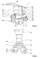
- FIG. 5 shows a preferred embodiment of the chassis device 1 in a side view. It can be seen the mounting plate 120, which covers the device 1 from above and projects beyond in the axial direction A. From the mounting plate 120, the box-shaped guide member 140 protrudes vertically downwards. The guide member 140 is fixedly secured to the mounting plate 120. Parallel to the mounting plate 120, the plate-shaped base member 160 extends on both sides of the guide member 140 in the axial direction A. Center with respect to the A direction in the base member 160, the receiving element 174 is mounted, which surrounds the box-shaped corresponding to the guide member 140 latter. How out Fig. 5 can be seen, the guide member 140 projects beyond the base plate 160 upwards and downwards. The protrusion of the exception member 174 substantially bridges the vertical distance between the base member 160 and the mounting plate 120 when the landing gear apparatus 1 is in the fully retracted condition as in FIG Fig. 5 located.
- the guide member 140 is hereby mounted centrally with respect to the axis direction A between the mounting plate 120 and the chassis 16, so that in the axial direction before and There is also space behind the guide element 140 for an actuating element mounted between the chassis 16 and the mounting plate 120.
- Fig. 5 It can also be seen that in the axial direction A, in the space to the left and to the right of the receiving element 174, two air bellows 141, 142 shown folded together extend between the base element 160 and the mounting plate 120. These air bellows 141, 142 serve as actuating means for actuating the extension and retraction movement of the chassis 16.
- the air bellows 141, 142 are connected via pressure lines 144 (see FIG. Fig. 5 and 11 ).
- the stop element 169 extends laterally downwards in each case.
- the base member 160 and the stopper members 169 are provided as a one-piece component.
- This component then has a U-shaped, downwardly open cross-sectional shape (see Fig. 6 ).
- the pivot axis S received between the stop elements 169 is fastened to the front side in suspensions 172, on which the guide arms 161 are pivoted between the starting position and the end position.
- the rollers 166 are mounted between the downwardly extending guide arms 161, the rollers 166 are mounted. The continuous first roller axis 167 can be seen.
- FIG. 6 shows in a front view of the embodiment of the chassis device 1 according to Fig. 5 ,
- the mounting plate 120 can be seen, under which the air bellows 141 extends down to the base member 160.
- the pivot axis S is fixed in the bearing 172 on the base element 160.
- the first and second guide arms 161, 162 which are oriented on the pivot axis S, extend at an angle downwards, the rollers 166 being in their end areas.
- the stop plates 176 can be seen, which extend below the recess 164 transversely to the longitudinal extension of the guide arms 161, 162.
- FIG. 7 is the embodiment of the suspension device 1 according to Fig. 5 shown from below.
- the first and second roller axes 167, 168 which are spaced apart in the direction of travel F, can be seen, on which the rollers 166 are mounted.
- the first and the second Guide arms 161, 162 offset from one another.
- the rollers 166 disposed on the first roller shaft 167 are offset from the rollers 166 disposed on the second roller axle 168.
- FIG. 7 further shows that the guide rollers 170 are provided laterally for guiding the landing gear device 1 in the receptacle 24 of the guard rail section 2. These guide rollers are attached via a bearing 171 to the stop plates 176 and additionally also to the inner guide arms 161 and 162.
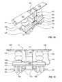
- FIG. 8 shows the embodiment of the chassis device 1 according to Fig. 5 in fully extended condition.
- the air bellows 141, 142 are inflated and thus actuated. This causes a distance between the mounting plate 120 and the base member 160 to be increased.
- the guide element 140 which is welded to the mounting plate 120, is telescopically extended from the receiving element 174. By this construction, an optimal guidance of the movement of the chassis 16 is made possible.
- the stop elements 169 abut the stop plates 176.
- the stop members 169 abut against the guide arms 161, 162.
- FIG. 9 is a frontal view of the embodiment in the position after Fig. 8 shows recognizable.
- the stop elements 169 engage in the recesses 164 of the guide arms 161, 162.
- FIGS. 10 and 11 show further perspective views of the chassis device 1 according Fig. 8 , LIST OF REFERENCE NUMBERS 1 suspension device 169 stop element 170 leadership 12 mounting element 171 Suspension of 169 120 mounting plate 172 Storage of S. 122 mounting holes 173 stop plate 174 Receptacle for 140 14 actuator 176 stop plate 140 guide element 141.142 bellows 2 guardrail section 144 Pressure line, supply line 21, 22 leg 145 cavity 23 opening 24 admission 16 chassis 26 bearing section 160 base element 161 first guide arm 3 travel plane 162 second guide arm 164 recess A horizontal axis direction 165 driving element B vertical direction of movement 166 role F horizontal direction of travel 167 first roll axis S horizontal swivel axis 168 second roller axis
Abstract
Description
Die vorliegende Erfindung betrifft eine Fahrwerkvorrichtung für ein Leitplankenleitsystem an Verkehrswegen nach dem Oberbegriff des Anspruchs 1 und einen mit dieser Fahrwerkvorrichtung verfahrbaren Leitplankenabschnitt.The present invention relates to a landing gear device for a crash barrier guidance system on traffic routes according to the preamble of
Leitplanken oder Leitsysteme werden standardmässig als Leiteinrichtung an Verkehrswegen, insbesondere im Mittelstreifen zwischen einzelnen Fahrbahnen mehrspuriger Strassen, bevorzugt vor Tunnels, zur schnellen Umleitung bei Unterhaltsarbeiten oder Verkehrsleitung angebracht. Eine stationäre Befestigung solcher leitenden Abgrenzungen birgt den Nachteil, dass eine temporäre Überleitung zwischen zwei durch die Leiteinrichtung getrennten Strassenbereichen nur durch zumindest teilweise Demontage der Befestigung ermöglicht wird.Guard rails or guidance systems are installed by default as a guide to traffic routes, especially in the median strip between individual lanes of multi-lane roads, preferably in front of tunnels, for rapid diversion during maintenance or traffic management. A stationary attachment of such conductive boundaries has the disadvantage that a temporary transition between two separated by the guide road areas is only possible by at least partial disassembly of the attachment.
Aus der
Die
Nachteilig ist hierbei, dass Leitplankensysteme mit bekannten Fahreinheiten zu unerwünschten Kippbewegungen neigen, was den Bewegungsvorgang negativ beeinflusst, insbesondere wenn der Untergrund, über welche die Rollen wälzen, uneben ist oder Risse bzw. aufliegende Fremdkörper aufweist.The disadvantage here is that guardrail systems with known driving units tend to undesirable tilting movements, which adversely affects the movement process, especially when the ground, over which roll the rollers, is uneven or has cracks or overlying foreign body.
Es ist daher eine Aufgabe der vorliegenden Erfindung, eine Fahrwerkvorrichtung für Leitplankensysteme anzugeben, welche ein zuverlässiges Verfahren oder Verschwenken beweglicher Leitplankenabschnitte erlaubt. Insbesondere soll eine Kippstabilität der beweglichen Leitplankenabschnitte erhöht werden.It is therefore an object of the present invention to provide a suspension device for guard rail systems, which allows a reliable method or pivoting movable guard rail sections. In particular, a tipping stability of the movable guard rail sections should be increased.
Diese Aufgabe wird durch den Gegenstand des Anspruchs 1 gelöst. Demgemäss wird eine Fahrwerkvorrichtung für ein Leitplankenleitsystem insbesondere an einem Verkehrsweg angegeben, wobei diese Fahrwerkvorrichtung
ein Montageelement zur Montage der Fahrwerksvorrichtung an einem Leitplankenabschnitt des Leitplankenleitsystems,
ein Fahrgestell zum Verfahren des Leitplankenabschnitts auf einer sich im Wesentlichen in der Horizontalen erstreckenden Fahrebene mittels der über das Montageelement am Leitplankenabschnitt montierten Fahrwerkeinrichtung,
ein Aktuatorelement, mittels welchem das Fahrgestell zwischen einer Ruheposition und Fahrposition aus- und einfahrbar ist, umfasst, wobei
das Fahrgestell mindestens ein Fahrelement aufweist, welches Fahrelement beim Ausfahren des Fahrgestells von der Ruheposition in die Fahrposition im Wesentlichen parallel zur Fahrebene ausklappbar ist.This object is solved by the subject matter of
a mounting element for mounting the landing gear device on a crash barrier section of the crash barrier guidance system,
a chassis for moving the crash barrier section on a substantially horizontally extending driving plane by means of the suspension device mounted on the guard rail section via the mounting element,
an actuator element, by means of which the chassis can be extended and retracted between a rest position and a driving position, wherein
the chassis has at least one driving element, which driving element during extension of the chassis from the rest position to the driving position substantially parallel to the driving plane is folded out.
Bevorzugt wird eine Fahrwerkvorrichtung, bei welcher das Fahrelement bezüglich einer rechtwinklig zur Fahrebene stehenden Ebene entlang einer Fahrrichtung ausklappbar ist und/oder wobei die besagte Bewegung des Fahrelements eine kombinierte Bewegung aus der genannten Ausfahrbewegung des Fahrgestells und der genannten Ausklappbewegung ist.A chassis device is preferred in which the traveling element can be folded along a direction of travel with respect to a plane that is perpendicular to the driving plane and / or wherein said movement of the driving element is a combined movement of said extending movement of the chassis and said unfolding movement.
In einem besonders bevorzugten Ausführungsbeispiel ist das Fahrelement durch die Ausklappbewegung zwischen einer Ausgangslage und einer Endlage derart bewegbar, dass das Fahrelement beim Ausfahren des Fahrgestells aus der Ruheposition in die Fahrposition von der Ausgangslage in die Endlage übergeht und beim Einfahren des Fahrgestells aus der Fahrposition in die Ruheposition von der Endlage in die Ausgangslage übergeht.In a particularly preferred embodiment, the driving element is movable by the Ausklappbewegung between a starting position and an end position such that the driving element when extending the chassis from the rest position to the driving position of the starting position merges into the end position and when retracting the chassis from the driving position in the Rest position moves from the end position to the starting position.
Hierbei ist die Horizontale die Richtung quer zur Wirkungsrichtung der Schwerkraft, wobei der Ausdruck "sich im Wesentlichen in der Horizontalen erstreckenden Ebene" so zu verstehen ist, dass diese Ebene auch um bis zu bspw. 15 Grad geneigt sein kann, wie es bei Autostrassen in Kurven bspw. vorkommen kann. Die Fahrtrichtung ist die Richtung, in welche das Fahrelement die Fahrwerksvorrichtung führt.Here, the horizontal is the direction transverse to the direction of gravity, whereby the expression "plane extending substantially in the horizontal plane" is to be understood as meaning that this plane may also be inclined by up to 15 degrees, as in the case of automobile streets Curves, for example, can occur. The direction of travel is the direction in which the driving element guides the chassis device.
Es ist also ein Aspekt der vorliegenden Erfindung, die Kippstabilität der verfahrenden Leitplankenabschnitte zu erhöhen, indem die in Vertikalrichtung aus- und einfahrbare Fahrwerkvorrichtung ein Fahrelement aufweist, welches horizontal zusammen- und auseinanderklappbar ist. In Staulage, d.h. in eingefahrenem Zustand mit dem Fahrelement in Ausgangslage, ist der Stauraum in einer Aufnahme des Leitplankenabschnitts durch das horizontal zusammengeklappte und vertikal eingefahrene Fahrelement optimal genutzt. Im eingefahrenen Zustand hängt das Fahrgestell vorzugsweise frei in der Aufnahme am Montageelement. Wenn das Fahrgestell in die Fahrposition ausgefahren ist, ist das Fahrelement auseinandergeklappt und das Fahrelement liegt in Endlage. Dadurch wird ein horizontaler Abstand der Auflagepunkte des Fahrelements von der Wirkungslinie der Gravitation auf einen Schwerpunkt der beweglichen Vorrichtung vergrössert, was die Kippmomente verkleinert und das Verlagern somit stabilisiert.It is therefore an aspect of the present invention to increase the tipping stability of the traveling guard rail sections in that the suspension device which can be extended and retracted in the vertical direction has a drive element which can be folded and folded horizontally. In a storage position, i. in the retracted state with the driving element in the starting position, the storage space is optimally used in a recording of the crash barrier section by the horizontally folded and vertically retracted drive element. When retracted, the chassis preferably hangs freely in the receptacle on the mounting element. When the chassis is extended to the driving position, the driving element is unfolded and the driving element is in the end position. Thereby, a horizontal distance of the support points of the driving element is increased from the line of gravity to a center of gravity of the movable device, which reduces the tilting moments and thus stabilizes the displacement.
Mittels der Fahrwerksvorrichtung können also Hebe- und Absenkvorgänge in Vertikalrichtung sowie Verfahr- oder Verlagerungsvorgänge in Fahrtrichtung eines am Montageelement befestigten Leitplankenabschnitts kontrolliert ausgeführt werden. Es ist auch denkbar, diese Bewegungsvorgänge ferngesteuert bzw. motorisiert-automatisch auszuführen.By means of the landing gear device, therefore, lifting and lowering operations in the vertical direction as well as traveling or shifting operations in the direction of travel of a guard rail section fastened to the mounting element can be carried out in a controlled manner. It is also conceivable to carry out these movement processes remotely or motorized-automatically.
In einem bevorzugten Ausführungsbeispiel weist das Fahrelement mindestens zwei in Fahrtrichtung in einem Abstand angeordnete Rollen auf, wobei dieser Abstand bei in Ausgangslage liegendem Fahrelement kleiner ist als bei in Endlage liegendem Fahrelement und wobei die beabstandeten Rollen vorzugsweise über eine Achse am Fahrgestell angeordnet sind, wobei diese Achse vorzugsweise eine gemeinsame Schwenkachse ist.In a preferred embodiment, the driving element has at least two rollers arranged at a distance in the direction of travel, wherein this distance is smaller when lying in the starting position driving element than lying in the end position driving element and wherein the spaced rollers are preferably arranged on an axle on the chassis, which Axis is preferably a common pivot axis.
Der Abstand der Rollen in Fahrtrichtung ist hierbei derart gross, dass die Fahrwerkvorrichtung stabil und breit auf dem Untergrund stehen kann, auch bei einem auf dem Montageelement aufliegenden Leitplankenabschnitt.The distance of the rollers in the direction of travel is in this case so large that the landing gear device can stand stable and wide on the ground, even with a resting on the mounting element guard rail section.
Eine einzelne Schwenkachse für die bezüglich der Fahrtrichtung nach hinten und die nach vorne verschwenkbaren Rollen erlaubt eine kompakte Bauweise mit einer minimalen Anzahl von Bauelementen.A single pivot axis for the rearward with respect to the direction of travel and the pivotable forward rollers allows a compact design with a minimum number of components.
Die Fahrwerksvorrichtung ist den benutzungsgemässen Lasten entsprechend stabil bspw. aus verschweissten Stahlelementen und Vollgummirollen gefertigt.The chassis device is the use according to loads correspondingly stable, for example. Made of welded steel elements and solid rubber wheels.
Vorzugsweise ist das Aktuatorelement zwischen dem Montageelement und dem Fahrgestell derart angeordnet, dass eine Bewegungsrichtung des Fahrgestells zwischen der Ruheposition und der Fahrposition im Wesentlichen rechtwinklig zur Fahrebene ist, wobei die Fahrwerkvorrichtung geeignet ist, das Fahrgestell unter Anhebung des Leitplankenabschnitts auszufahren und unter Absenkung des Leitplankenabschnitts einzufahren. Das Aktuatorelement ist also in der Lage, das Montageelement und das Fahrgestell auseinanderzudrücken und wieder kontrolliert zusammenzuführen unter Hebung bzw. Senkung des Leitplankenabschnitts.Preferably, the actuator element between the mounting member and the chassis is arranged such that a direction of movement of the chassis between the rest position and the driving position is substantially perpendicular to the driving plane, wherein the chassis device is adapted to extend the chassis while raising the crash barrier section and retracting under lowering of the guard rail section , Thus, the actuator element is able to push apart the assembly element and the chassis and bring it back together in a controlled manner while raising or lowering the guard rail section.
Zur optimalen Kontrolle dieser Betätigung ist vorzugsweise ein Führungselement zwischen dem Montageelement und dem Fahrgestell zur Führung der aktuatorelementbetätigten Ausfahr- und Einfahrbewegung des Fahrgestells in Bewegungsrichtung angeordnet, wobei dieses Führungselement vorzugsweise ein teleskopisches Führungselement ist. Unter dem Begriff "telekopisches Führungselement" ist ein Führungselement gemeint, welches teleskopierbare Elemente umfasst oder welches sich teleskopisch in ein weiteres Element einfügt.For optimum control of this operation, a guide element is preferably arranged between the mounting element and the chassis for guiding the actuator-actuated extension and retraction movement of the chassis in the direction of movement, this guide element preferably being a telescopic guide element. By the term "telecopic guide element" is meant a guide element which comprises telescoping elements or which telescopes into another element.
Vorteilhafterweise umfasst das Fahrgestell ein Basiselement, einen zwischen der Ausgangslage und der Endlage im Wesentlichen in Fahrtrichtung verschwenkbaren ersten Führungsarm und einen zwischen der Ausgangslage und der Endlage im Wesentlichen entgegen der Fahrtrichtung verschwenkbaren zweiten Führungsarm. Der erste und der zweite Führungsarm sind jeweils am Basiselement derart verschwenkbar angeachst, dass der erste Führungsarm aus der Ausgangslage in die Fahrtrichtung in die Endlage verschwenkbar ist und der zweite Führungsarm aus der Ausgangslage entgegen der Fahrtrichtung in die Endlage verschwenkbar ist. An freien Endabschnitten der ersten und zweiten Führungsarme sind die Rollen zum Rollkontakt mit der Ebene als Fahrelement angeachst. Es wird also bevorzugt, als Klappmechanismus verschwenkbare Führungsarme vorzusehen, an welchen Rollen montiert sind, wobei die Rollen in Ausgangslage horizontal so nahe beisammen liegen, dass die entsprechende Aufnahme im Leitplankenabschnitt bei der in Ruheposition liegenden Fahrwerkvorrichtung optimal ausgenutzt ist. Der Klappmechanismus ist weiter vorzugsweise derart ausgestaltet, dass die Rollen in Endlage auseinandergeklappt oder -geschwenkt sind, so dass die Auflagepunkte der Rollen auf dem Untergrund möglichst breit und stabil stehen. Der Klappmechanismus ist also vorteilhaft im Zielkonflikt der Einhaltung begrenzter Aufnahmekapazität des zu verlagernden Leitplankenabschnitts bzw. der damit verbundenen Abmessungsbeschränkung und einer möglichst stabilen und daher breiten Auflage des Fahrelements zur Verringerung der Kippneigung in entlang der Fahrtrichtung.Advantageously, the chassis comprises a base element, one between the Starting position and the end position substantially pivotable in the direction of travel first guide arm and between the starting position and the end position substantially against the direction of travel pivotable second guide arm. The first and the second guide arm are respectively pivoted on the base element in such a way that the first guide arm can be pivoted out of the initial position in the direction of travel into the end position and the second guide arm can be pivoted out of the initial position counter to the direction of travel into the end position. At free end portions of the first and second guide arms, the rollers are arranged for rolling contact with the plane as the driving element. It is therefore preferable to provide pivotable guide arms as folding mechanism, on which rollers are mounted, wherein the rollers are horizontally so close to each other in the starting position that the corresponding receptacle in the guard rail section is optimally utilized in the suspension device lying in the rest position. The folding mechanism is further preferably designed such that the rollers are unfolded or pivoted in the end position, so that the contact points of the rollers stand as broad and stable as possible on the ground. The folding mechanism is thus advantageous in the conflict of objectives of adherence to limited absorption capacity of the guardrail section to be displaced or the associated dimensional restriction and a stable and therefore wide edition of the driving element to reduce tilt in along the direction of travel.
Vorzugsweise umfasst die Fahrwerkvorrichtung weiter ein Anschlagelement zum Anschlag der jeweils in die Endlage verschwenkten ersten und zweiten Führungsarme, wobei das Anschlagelement vorzugsweise fest am Fahrgestell, insbesondere am Basiselement angeordnet ist und gegebenenfalls die Führungsarme vorzugsweise an derselben Schwenkachse am Basiselement angeachst sind.Preferably, the landing gear device further comprises a stop element for abutment of the respective first and second guide arms pivoted into the end position, wherein the stop element is preferably fixedly arranged on the chassis, in particular on the base element and optionally the guide arms are preferably aligned on the same pivot axis on the base element.
Um die Stabilität weiter zu erhöhen, ist es von Vorteil, wenn in einer abermaligen Weiterbildung eine Vielzahl von ersten und zweiten Führungsarmen im Basiselement in horizontaler Achsenrichtung der Schwenkachse angeordnet sind, wobei vorzugsweise die Rollen der ersten Führungsarme über eine gemeinsame, durchgehende erste Rollenachse gelagert sind und die Rollen der zweiten Führungsarme über eine gemeinsame, durchgehende zweite Rollenachse gelagert sind. Diese Rollenachsen verlaufen parallel zueinander in Achsenrichtung, wobei vorzugsweise jede Rolle beidseitig in Achsenrichtung in jeweils einem entsprechenden Führungsarm gefasst ist.In order to increase the stability further, it is advantageous if in a repeated development a plurality of first and second guide arms are arranged in the base element in the horizontal axis direction of the pivot axis, wherein preferably the rollers of the first guide arms are mounted on a common, continuous first roller axis and the rollers of the second guide arms are supported via a common, continuous second roller axle. These roller axes are parallel to each other in the axial direction, wherein preferably each roller is taken on both sides in the direction of the axis in each case a corresponding guide arm.
Es ist also ein Aspekt dieser Weiterbildung, nicht nur zwei in Fahrtrichtung beabstandete Rollen, sondern zwei in Fahrtrichtung beabstandeten Rollenpakete von in Achsenrichtung angeordneten Rollen vorzusehen. Diese Rollenpakete können hierbei in Achsenrichtung wieder näher zusammengerückte Unterpakete oder Untergruppen mit grösseren Abständen dazwischen bilden.It is therefore an aspect of this development, not only two rollers spaced in the direction of travel, but to provide two spaced apart in the direction of travel roller packages of rollers arranged in the axial direction. These role packages can form subpackets or subgroups closer together in the axial direction with larger distances between them.
Vorzugsweise sind die ersten Führungsarme jeweils in der Achsenrichtung versetzt zu den zweiten Führungsarmen angeordnet. Dies erhöht die Stabilität weiter, wobei dann auch die Rollen an der ersten Rollenachse versetzt zu den Rollen an der zweiten Rollenachse angeordnet sind.Preferably, the first guide arms are each arranged offset in the axial direction to the second guide arms. This further increases the stability, in which case also the rollers on the first roller axle are arranged offset from the rollers on the second roller axle.
Um eine störungsfreie Bewegung des Fahrgestells relativ zum Montageelement zu ermöglichen, ist es vorteilhaft, wenn die Fahrwerkvorrichtung weiter Führungsrollen zur Seitenführung des Ausfahr- und Einfahrbewegung am Leitplankenabschnitt, d.h. entlang dessen innwendiger Aufnahme, umfasst.In order to enable a trouble-free movement of the chassis relative to the mounting element, it is advantageous if the landing gear device continues to guide rollers for lateral guidance of the extension and retraction movement on the guard rail section, i. along its internal receptacle.
Bevorzugt sind Aktuatorelemente, welche elektrisch oder fluidisch betätigbar ist, wobei das Aktuatorelement vorzugsweise mindestens einen Luftbalg, vorzugsweise genau zwei Luftbalge umfasst, welche pneumatisch betätigbar sind. Das Aktuatorelement kann alternativ oder zusätzlich ein vorzugsweise mittig, im Hohlraum des Führungselements untergebrachtes Getriebe, insbesondere ein Zahnstangengetriebe umfassen, welches über eine Kurbel betätigbar ist, wobei die Kurbel insbesondere eine Handkurbel zur Handbetätigung ist (z.B. zur Notbedienung bei Stromausfall).Preference is given to actuator elements which can be actuated electrically or fluidically, wherein the actuator element preferably comprises at least one air bellows, preferably exactly two air bellows, which are pneumatically actuated. The actuator element may alternatively or additionally comprise a preferably centered, housed in the cavity of the guide member gear, in particular a rack gear which is actuated via a crank, wherein the crank is in particular a hand crank for manual operation (for example, for emergency operation in case of power failure).
Es ist eine weitere Aufgabe der vorliegenden Erfindung, einen stabil verfahrbaren Leitplankenabschnitt anzugeben. Diese Aufgabe wird durch einen Leitplankenabschnitt mit mindestens einer hierin beschriebenen Fahrwerksvorrichtung gelöst.It is a further object of the present invention to provide a stably movable guardrail section. This object is achieved by a crash barrier section having at least one landing gear device described herein.
In einer Weiterbildung dieses Leitplankenabschnitts sind eine Vielzahl von vorgenannten Fahrwerksvorrichtungen vorgesehen, wobei die Fahrwerksvorrichtung vorzugsweise in einem insbesondere regelmässigen Längsabstand entlang der Längserstreckung des Leitplankenabschnittes, dh in Achsenrichtung der Fahrwerkvorrichtung, angeordnet sind, wobei dieser Längsabstand 4 bis 10 Meter, insbesondere im Wesentlichen 3 bis 5 Meter beträgt.In a further development of this crash barrier section, a plurality of aforementioned landing gear devices are provided, wherein the landing gear device is preferably arranged in a particularly regular longitudinal distance along the longitudinal extent of the guard rail section, ie in the axial direction of the landing gear device, this longitudinal distance being 4 to 10 meters, in particular substantially 3 to 5 meters.
Bevorzugt wird, wenn der Leitplankenabschnitt eine im Wesentlichen U-förmige Querschnittsgestalt mit nach unten gerichteter Öffnung aufweist, wobei die Fahrwerksvorrichtung in die zwischen die U-Form bildenden Schenkeln des Leitplankenabschnitts gebildete Aufnahme vorzugsweise vollständig einfahrbar ist, wobei der Leitplankenabschnitt bei eingefahrener Fahrwerkvorrichtung vorzugsweise auf seitlich auskragenden Endabschnitten der Schenkel ruht und bei ausgefahrener Fahrwerksvorrichtung von der Ebene angehoben auf dem Fahrelement aufliegt und auf dem Fahrelement in Fahrtrichtung verfahrbar bzw. verlagerbar ist.It is preferred if the guard rail portion is a substantially U-shaped Cross-sectional shape having downwardly directed opening, wherein the landing gear device is preferably fully retractable in the formed between the U-shape legs of the guard rail portion, the guard rail portion preferably rests on retracted landing gear on laterally projecting end portions of the legs and extended in the landing gear device of the plane lifted rests on the driving element and is movable or displaceable on the driving element in the direction of travel.
Bevorzugte Ausführungsformen der Erfindung werden im Folgenden anhand der Zeichnungen beschrieben, die lediglich zur Erläuterung dienen und nicht einschränkend auszulegen sind. In den Zeichnungen zeigen:
- Fig. 1
- in schematischer Form einen Querschnitt durch einen auf einem ebenen Untergrund ruhenden Leitplankenabschnitt mit einer erfindungsgemässen Fahrwerkvorrichtung in vollständig eingefahrenem Zustand;
- Fig. 2
- einen Längsschnitt durch die Fahrwerkvorrichtung gemäss
Fig. 1 , wobei die Fahrwerkvorrichtung erneut in eingefahrenem Zustand dargestellt ist; - Fig. 3
- in schematischer Form einen Querschnitt den Leitplankenabschnitt mit der Fahrwerkvorrichtung gemäss
Fig. 1 , wobei die Fahrwerkvorrichtung in vollständig ausgefahrenem Zustand dargestellt ist; - Fig. 4
- einen Längsschnitt durch die Fahrwerkvorrichtung gemäss
Fig. 3 , wobei die Fahrwerkvorrichtung erneut in ausgefahrenem Zustand dargestellt ist; - Fig. 5
- in einer Seitenansicht eine bevorzugte Ausführungsform der erfindungsgemässen Fahrwerkvorrichtung in vollständig eingefahrenem Zustand;
- Fig. 6
- in einer Frontansicht die eingefahrene Fahrwerksvorrichtung gemäss
Fig. 5 ; - Fig. 7
- in einer Untenansicht die eingefahrene Fahrwerksvorrichtung gemäss
Fig. 5 ; - Fig. 8
- in einer perspektivischen Ansicht die Fahrwerkvorrichtung gemäss
Fig. 5 in vollständig ausgefahrenem Zustand; - Fig. 9
- in einer Frontansicht die ausgefahrene Fahrwerkvorrichtung gemäss
Fig. 8 ; - Fig. 10
- in einer perspektivischen Ansicht von oben die ausgefahrene Fahrwerkvorrichtung gemäss
Fig. 8 ; und - Fig. 11
- in einer Seitenansicht die ausgefahrene Fahrwerkvorrichtung gemäss
Fig. 8 .
- Fig. 1
- in schematic form a cross section through a resting on a flat surface guard rail section with an inventive suspension device in fully retracted state;
- Fig. 2
- a longitudinal section through the suspension device according
Fig. 1 wherein the landing gear device is shown again in the retracted state; - Fig. 3
- in schematic form a cross section of the guard rail section with the landing gear device according to
Fig. 1 wherein the landing gear device is shown in fully extended condition; - Fig. 4
- a longitudinal section through the suspension device according
Fig. 3 , wherein the landing gear device is shown again in the extended state; - Fig. 5
- in a side view of a preferred embodiment of the inventive suspension device in fully retracted state;
- Fig. 6
- in a front view of the retracted suspension device according
Fig. 5 ; - Fig. 7
- in a bottom view of the retracted landing gear device according
Fig. 5 ; - Fig. 8
- in a perspective view of the landing gear device according
Fig. 5 in fully extended condition; - Fig. 9
- in a front view of the extended landing gear device according
Fig. 8 ; - Fig. 10
- in a perspective view from above the extended landing gear device according
Fig. 8 ; and - Fig. 11
- in a side view of the extended landing gear device according
Fig. 8 ,
Anhand der schematischen
Aus
In der Aufnahme 24 ist die Fahrwerkvorrichtung 1 untergebracht bzw. montiert. Die Fahrwerkvorrichtung 1 umfasst ein Montageelement 12, ein Aktuatorelement 14 mit einem Führungselement 140 und ein Fahrgestell 16. Das Montageelement 12 dient zur Befestigung der Fahrwerkvorrichtung 1 am Leitplankenabschnitt 2. Das Fahrgestell 16 dient mit seinem Fahrelement 165 als Rollauflage für den zu verfahrenden Leitplankenabschnitt 2. Das Aktuatorelement 14 mit dem Führungselement 140 dient zum Ausfahren beziehungsweise Einfahren des Fahrelements 165 aus der Aufnahme 24 des Leitplankenabschnitts 2. Das Führungselement 140 führt die vertikale Ausfahr- und Einfahrbewegung des Fahrgestells 16 bezüglich des Montagelements 12 in vertikaler Bewegungsrichtung B. Ist die Fahrwerkvorrichtung 1 eingefahren, so hängt sie in der Aufnahme 24 am Montageelement 12; ist sie ausgefahren, so stemmt sie sich von Ebene 3 aus gegen ein oberes Ende (den Boden der U-Form) des Leitplankenabschnitts 2 und hebt letzteren hoch. Die Aufnahme 24 wird durch die eingefahrene Fahrwerkvorrichtung 1 im Wesentlichen ausgefüllt.In the
Wie im oberen Bereich der
An das im Querschnitt viereckige Führungselement 140 schliesst sich unten das in vertikaler Bewegungsrichtung B verfahrbare Fahrgestell 16 an.
An das Aufnahmeelement 174 schliesst sich entlang der Achsenrichtung A ein Basiselement 160 an. Das Aufnahmeelement 174 und das Basiselement 160 sind fest verbunden. Von diesem plattenförmig ausgestalteten Basiselement 160 erstrecken sich in vertikaler Bewegungsrichtung B nach unten plattenförmige Anschlagelemente 169. Das Basiselement 160 und die Anschlagelemente 169 weisen ebenfalls eine U-förmige Querschnittsform mit einer Öffnung nach unten auf. Zwischen den sich plattenförmig in Achsenrichtung A entlang des Basiselements 160 erstreckenden Anschlagelementen 169 ist die Schwenkachse S angeordnet. Die Schwenkachse S ist am Basiselement 160 befestigt. An dieser Schwenkachse S sind zwei nach unten in vertikaler Bewegungsrichtung B ragende Schwenkarme 161, 162 verschwenkbar angelenkt. Die flachen, einstückig und starr ausgeformten Schwenkarme 161, 162 erstrecken sich winklig zur Vertikalrichtung B nach unten, wobei in deren Endbereichen die Rollen 166 angeachst sind. Die Rollen 166 überragen die Schwenkarme 161, 162 entlang der Längserstreckung der Arme 161, 162 und quer dazu.A
In
Weiter ist in
Des Weiteren ist erkennbar, dass das Führungselement 140 teilweise aus der Tiefe der Aufnahme des Aufnahmeelements 174 ausgefahren ist, jedoch weiterhin in diese Aufnahme unter seitlichem Führungskontakt eingreift. Das Führungselement 140 und das Aufnahmeelement 174 sind somit teleskopisch zueinander verschiebbar. Das heisst, dass eine Höhe der Fahrwerkvorrichtung 1 in Vertikalrichtung bzw. Bewegungsrichtung B gegenüber der Anordnung der
Durch diese Vergrösserung des Winkels wird also ein Abstand in Fahrtrichtung F zwischen der ersten und zweiten Rollenachse 167, 168 vergrössert, womit die Auflagepunkte der Rollen 166 einen vergrösserten Abstand aufweisen, was die Kippstabilität des angehobenen Leitplankenabschnitts 2 erhöht. Durch den vergrösserten Abstand in Endlage gemäss
In
Wie aus
Die Schwenkbewegung der Führungsarme 161, 162 von der Endlage zurück in die Ausgangslage wird ebenfalls durch die Anschlagplatten 176 begrenzt, welche sich bis zwischen die ersten bzw. zweiten Führungsarme 161, 162 gegeneinander erstrecken, derart, dass die Anschlagplatte 176 der ersten Führungsarme 161 einen Anschlag für die zweiten Führungsarme 162 bildet und umgekehrt.The pivotal movement of the
In den
Anhand der
Das Führungselement 140 ist hierbei mittig bezüglich der Achsenrichtung A zwischen der Montageplatte 120 und dem Fahrgestell 16 angebracht, so dass in Achsenrichtung vor und hinter dem Führungselement 140 ebenfalls Raum für ein zwischen Fahrgestell 16 und Montageplatte 120 angebrachtes Betätigungselement besteht. In
Vom Basiselement 160 erstreckt sich jeweils seitlich das Anschlagelement 169 nach unten. Vorzugsweise sind das Basiselement 160 und die Anschlagselemente 169 als einstückiges Bauteil vorgesehen. Dieses Bauteil weist dann eine U-formige, nach unten offene Querschnittsform auf (siehe
In
Die
Claims (15)
ein Montageelement (12) zur Montage der Fahrwerksvorrichtung (1) an einem Leitplankenabschnitt (2) des Leitsystems,
ein Fahrgestell (16) zum Verfahren des Leitplankenabschnitts (2) auf einer sich im Wesentlichen in der Horizontalen erstreckenden Fahrebene (3) mittels der über das Montageelement (12) am Leitplankenabschnitt (2) montierten Fahrwerkeinrichtung (1),
ein Aktuatorelement (14), mittels welchem das Fahrgestell (16) zwischen einer Ruheposition und Fahrposition aus- und einfahrbar ist, dadurch gekennzeichnet, dass
das Fahrgestell (16) mindestens ein Fahrelement (165) aufweist, welches Fahrelement (165) beim Ausfahren des Fahrgestells (16) von der Ruheposition in die Fahrposition im Wesentlichen parallel zur Fahrebene (3) ausklappbar ist.Comprising landing gear device (1) for a guidance system, in particular on a traffic route
a mounting element (12) for mounting the landing gear device (1) on a crash barrier section (2) of the guidance system,
a chassis (16) for moving the crash barrier section (2) on a traveling plane (3) extending substantially in the horizontal direction by means of the chassis device (1) mounted on the guard rail section (2) via the mounting element (12),
an actuator element (14), by means of which the chassis (16) between a rest position and driving position off and retractable, characterized in that
the chassis (16) has at least one driving element (165), which driving element (165) during extension of the chassis (16) from the rest position to the driving position substantially parallel to the driving plane (3) can be folded out.
Priority Applications (1)
| Application Number | Priority Date | Filing Date | Title |
|---|---|---|---|
| EP13161348.1A EP2784221B1 (en) | 2013-03-27 | 2013-03-27 | Travelling device for guard rail systems |
Applications Claiming Priority (1)
| Application Number | Priority Date | Filing Date | Title |
|---|---|---|---|
| EP13161348.1A EP2784221B1 (en) | 2013-03-27 | 2013-03-27 | Travelling device for guard rail systems |
Publications (2)
| Publication Number | Publication Date |
|---|---|
| EP2784221A1 true EP2784221A1 (en) | 2014-10-01 |
| EP2784221B1 EP2784221B1 (en) | 2016-10-12 |
Family
ID=48047824
Family Applications (1)
| Application Number | Title | Priority Date | Filing Date |
|---|---|---|---|
| EP13161348.1A Active EP2784221B1 (en) | 2013-03-27 | 2013-03-27 | Travelling device for guard rail systems |
Country Status (1)
| Country | Link |
|---|---|
| EP (1) | EP2784221B1 (en) |
Cited By (3)
| Publication number | Priority date | Publication date | Assignee | Title |
|---|---|---|---|---|
| US10697140B2 (en) | 2016-01-05 | 2020-06-30 | Wenger, Projekte Und Coaching | Movable crash barrier section |
| CN112030833A (en) * | 2020-08-29 | 2020-12-04 | 河南交院工程技术有限公司 | Concrete movable guardrail for expressway runway |
| KR102592966B1 (en) * | 2023-03-29 | 2023-10-23 | 주식회사 태경씨앤씨 | Guardrail movable weeding device and guardrail movable weeding system containing this |
Families Citing this family (1)
| Publication number | Priority date | Publication date | Assignee | Title |
|---|---|---|---|---|
| CN110374031A (en) * | 2019-07-19 | 2019-10-25 | 河南工程学院 | The converting means and method in highway bridge tide lane |
Citations (5)
| Publication number | Priority date | Publication date | Assignee | Title |
|---|---|---|---|---|
| DE9308265U1 (en) * | 1993-06-02 | 1993-07-22 | Sps Schutzplanken Gmbh, 8750 Aschaffenburg, De | |
| FR2741093A1 (en) * | 1995-11-14 | 1997-05-16 | Studia | Continuous movable divider especially between traffic lanes of highway |
| DE60014502T2 (en) | 1999-06-18 | 2006-02-09 | Colas | Passage in guardrails of roadways |
| DE102007027453A1 (en) * | 2007-06-11 | 2008-12-24 | Outimex Ag | Adapter unit for conduction mechanism at traffic routes, has two adaptor pieces, where adaptor pieces are connected with segment of conduction mechanism and has joint units in each case |
| EP2107164A2 (en) | 2008-04-01 | 2009-10-07 | Heintzmann Sicherheitssysteme GmbH & Co. KG | Safety barrier on roadways |
-
2013
- 2013-03-27 EP EP13161348.1A patent/EP2784221B1/en active Active
Patent Citations (5)
| Publication number | Priority date | Publication date | Assignee | Title |
|---|---|---|---|---|
| DE9308265U1 (en) * | 1993-06-02 | 1993-07-22 | Sps Schutzplanken Gmbh, 8750 Aschaffenburg, De | |
| FR2741093A1 (en) * | 1995-11-14 | 1997-05-16 | Studia | Continuous movable divider especially between traffic lanes of highway |
| DE60014502T2 (en) | 1999-06-18 | 2006-02-09 | Colas | Passage in guardrails of roadways |
| DE102007027453A1 (en) * | 2007-06-11 | 2008-12-24 | Outimex Ag | Adapter unit for conduction mechanism at traffic routes, has two adaptor pieces, where adaptor pieces are connected with segment of conduction mechanism and has joint units in each case |
| EP2107164A2 (en) | 2008-04-01 | 2009-10-07 | Heintzmann Sicherheitssysteme GmbH & Co. KG | Safety barrier on roadways |
Cited By (3)
| Publication number | Priority date | Publication date | Assignee | Title |
|---|---|---|---|---|
| US10697140B2 (en) | 2016-01-05 | 2020-06-30 | Wenger, Projekte Und Coaching | Movable crash barrier section |
| CN112030833A (en) * | 2020-08-29 | 2020-12-04 | 河南交院工程技术有限公司 | Concrete movable guardrail for expressway runway |
| KR102592966B1 (en) * | 2023-03-29 | 2023-10-23 | 주식회사 태경씨앤씨 | Guardrail movable weeding device and guardrail movable weeding system containing this |
Also Published As
| Publication number | Publication date |
|---|---|
| EP2784221B1 (en) | 2016-10-12 |
Similar Documents
| Publication | Publication Date | Title |
|---|---|---|
| DE1944214A1 (en) | Slewing crane chassis | |
| EP2500230B1 (en) | Bridge for the intersection of two vehicle sections with a jointed connection | |
| WO1998054081A1 (en) | Crane with telescope jib | |
| EP2784221B1 (en) | Travelling device for guard rail systems | |
| DE202009008233U1 (en) | wagon | |
| DE102005022094A1 (en) | Forklift with extending platform for battery, comprises recesses for accommodation of rollers when in resting position | |
| EP2995526A1 (en) | Rail vehicle and clutch assembly for the rail vehicle, and method for coupling the railway vehicle with a second rail vehicle | |
| DE102015008651B4 (en) | Crane, preferably derrick | |
| DE1241092B (en) | System for parking a second passenger car over a first car | |
| DE102019126356A1 (en) | ENTRANCE SYSTEM FOR A DOOR AREA OF A PASSENGER TRANSPORT VEHICLE AND PASSENGER TRANSPORT VEHICLE | |
| DE3429895C2 (en) | ||
| EP1743611B1 (en) | Extensible ramp for public service vehicles | |
| DE2138468A1 (en) | REACTABLE CRANE | |
| DE102006050431A1 (en) | Industrial truck, in particular counterweight-forklift trucks, has vehicle frame with framework section for accommodating battery block that is reachable and extendable transverse to vehicle longitudinal axis | |
| DE3332227C2 (en) | Bridge viewing device | |
| DE19737678A1 (en) | Vehicle with frame support | |
| EP3197817B1 (en) | Supporting leg and supporting construction for a working machine | |
| EP2594450B1 (en) | Intersection half between two loose jointed vehicles of a rail car | |
| EP3847324B1 (en) | Transport device for moving heavy loads | |
| EP3007954A1 (en) | Central climbing protection for rail vehicles with additional functions | |
| DE1031726B (en) | Device for vehicles, in particular motor vehicles, for carrying a mobile container on the loading area | |
| DE2361235B2 (en) | Extension element for the provisional extension of stretches in the area of the face | |
| DE3340739A1 (en) | Track construction machine for exchanging a mounted track section or a mounted track connection | |
| DE102015012757B4 (en) | Rail guide device for two-way vehicles | |
| DE3412065A1 (en) | Loading bridge |
Legal Events
| Date | Code | Title | Description |
|---|---|---|---|
| 17P | Request for examination filed |
Effective date: 20130327 |
|
| AK | Designated contracting states |
Kind code of ref document: A1 Designated state(s): AL AT BE BG CH CY CZ DE DK EE ES FI FR GB GR HR HU IE IS IT LI LT LU LV MC MK MT NL NO PL PT RO RS SE SI SK SM TR |
|
| AX | Request for extension of the european patent |
Extension state: BA ME |
|
| PUAI | Public reference made under article 153(3) epc to a published international application that has entered the european phase |
Free format text: ORIGINAL CODE: 0009012 |
|
| R17P | Request for examination filed (corrected) |
Effective date: 20150206 |
|
| RBV | Designated contracting states (corrected) |
Designated state(s): AL AT BE BG CH CY CZ DE DK EE ES FI FR GB GR HR HU IE IS IT LI LT LU LV MC MK MT NL NO PL PT RO RS SE SI SK SM TR |
|
| RIC1 | Information provided on ipc code assigned before grant |
Ipc: E01F 15/00 20060101AFI20160330BHEP |
|
| GRAP | Despatch of communication of intention to grant a patent |
Free format text: ORIGINAL CODE: EPIDOSNIGR1 |
|
| INTG | Intention to grant announced |
Effective date: 20160510 |
|
| GRAS | Grant fee paid |
Free format text: ORIGINAL CODE: EPIDOSNIGR3 |
|
| GRAA | (expected) grant |
Free format text: ORIGINAL CODE: 0009210 |
|
| AK | Designated contracting states |
Kind code of ref document: B1 Designated state(s): AL AT BE BG CH CY CZ DE DK EE ES FI FR GB GR HR HU IE IS IT LI LT LU LV MC MK MT NL NO PL PT RO RS SE SI SK SM TR |
|
| REG | Reference to a national code |
Ref country code: GB Ref legal event code: FG4D Free format text: NOT ENGLISH |
|
| REG | Reference to a national code |
Ref country code: CH Ref legal event code: EP |
|
| REG | Reference to a national code |
Ref country code: AT Ref legal event code: REF Ref document number: 836633 Country of ref document: AT Kind code of ref document: T Effective date: 20161015 |
|
| REG | Reference to a national code |
Ref country code: IE Ref legal event code: FG4D Free format text: LANGUAGE OF EP DOCUMENT: GERMAN |
|
| REG | Reference to a national code |
Ref country code: DE Ref legal event code: R096 Ref document number: 502013004915 Country of ref document: DE |
|
| REG | Reference to a national code |
Ref country code: CH Ref legal event code: NV Representative=s name: ISLER AND PEDRAZZINI AG, CH |
|
| REG | Reference to a national code |
Ref country code: NL Ref legal event code: FP |
|
| REG | Reference to a national code |
Ref country code: LT Ref legal event code: MG4D |
|
| PG25 | Lapsed in a contracting state [announced via postgrant information from national office to epo] |
Ref country code: LV Free format text: LAPSE BECAUSE OF FAILURE TO SUBMIT A TRANSLATION OF THE DESCRIPTION OR TO PAY THE FEE WITHIN THE PRESCRIBED TIME-LIMIT Effective date: 20161012 |
|
| REG | Reference to a national code |
Ref country code: FR Ref legal event code: PLFP Year of fee payment: 5 |
|
| PG25 | Lapsed in a contracting state [announced via postgrant information from national office to epo] |
Ref country code: LT Free format text: LAPSE BECAUSE OF FAILURE TO SUBMIT A TRANSLATION OF THE DESCRIPTION OR TO PAY THE FEE WITHIN THE PRESCRIBED TIME-LIMIT Effective date: 20161012 Ref country code: NO Free format text: LAPSE BECAUSE OF FAILURE TO SUBMIT A TRANSLATION OF THE DESCRIPTION OR TO PAY THE FEE WITHIN THE PRESCRIBED TIME-LIMIT Effective date: 20170112 Ref country code: SE Free format text: LAPSE BECAUSE OF FAILURE TO SUBMIT A TRANSLATION OF THE DESCRIPTION OR TO PAY THE FEE WITHIN THE PRESCRIBED TIME-LIMIT Effective date: 20161012 Ref country code: GR Free format text: LAPSE BECAUSE OF FAILURE TO SUBMIT A TRANSLATION OF THE DESCRIPTION OR TO PAY THE FEE WITHIN THE PRESCRIBED TIME-LIMIT Effective date: 20170113 |
|
| PG25 | Lapsed in a contracting state [announced via postgrant information from national office to epo] |
Ref country code: HR Free format text: LAPSE BECAUSE OF FAILURE TO SUBMIT A TRANSLATION OF THE DESCRIPTION OR TO PAY THE FEE WITHIN THE PRESCRIBED TIME-LIMIT Effective date: 20161012 Ref country code: PL Free format text: LAPSE BECAUSE OF FAILURE TO SUBMIT A TRANSLATION OF THE DESCRIPTION OR TO PAY THE FEE WITHIN THE PRESCRIBED TIME-LIMIT Effective date: 20161012 Ref country code: RS Free format text: LAPSE BECAUSE OF FAILURE TO SUBMIT A TRANSLATION OF THE DESCRIPTION OR TO PAY THE FEE WITHIN THE PRESCRIBED TIME-LIMIT Effective date: 20161012 Ref country code: PT Free format text: LAPSE BECAUSE OF FAILURE TO SUBMIT A TRANSLATION OF THE DESCRIPTION OR TO PAY THE FEE WITHIN THE PRESCRIBED TIME-LIMIT Effective date: 20170213 Ref country code: FI Free format text: LAPSE BECAUSE OF FAILURE TO SUBMIT A TRANSLATION OF THE DESCRIPTION OR TO PAY THE FEE WITHIN THE PRESCRIBED TIME-LIMIT Effective date: 20161012 Ref country code: ES Free format text: LAPSE BECAUSE OF FAILURE TO SUBMIT A TRANSLATION OF THE DESCRIPTION OR TO PAY THE FEE WITHIN THE PRESCRIBED TIME-LIMIT Effective date: 20161012 Ref country code: IS Free format text: LAPSE BECAUSE OF FAILURE TO SUBMIT A TRANSLATION OF THE DESCRIPTION OR TO PAY THE FEE WITHIN THE PRESCRIBED TIME-LIMIT Effective date: 20170212 |
|
| REG | Reference to a national code |
Ref country code: DE Ref legal event code: R097 Ref document number: 502013004915 Country of ref document: DE |
|
| PG25 | Lapsed in a contracting state [announced via postgrant information from national office to epo] |
Ref country code: RO Free format text: LAPSE BECAUSE OF FAILURE TO SUBMIT A TRANSLATION OF THE DESCRIPTION OR TO PAY THE FEE WITHIN THE PRESCRIBED TIME-LIMIT Effective date: 20161012 Ref country code: EE Free format text: LAPSE BECAUSE OF FAILURE TO SUBMIT A TRANSLATION OF THE DESCRIPTION OR TO PAY THE FEE WITHIN THE PRESCRIBED TIME-LIMIT Effective date: 20161012 Ref country code: DK Free format text: LAPSE BECAUSE OF FAILURE TO SUBMIT A TRANSLATION OF THE DESCRIPTION OR TO PAY THE FEE WITHIN THE PRESCRIBED TIME-LIMIT Effective date: 20161012 Ref country code: CZ Free format text: LAPSE BECAUSE OF FAILURE TO SUBMIT A TRANSLATION OF THE DESCRIPTION OR TO PAY THE FEE WITHIN THE PRESCRIBED TIME-LIMIT Effective date: 20161012 Ref country code: SK Free format text: LAPSE BECAUSE OF FAILURE TO SUBMIT A TRANSLATION OF THE DESCRIPTION OR TO PAY THE FEE WITHIN THE PRESCRIBED TIME-LIMIT Effective date: 20161012 |
|
| PLBE | No opposition filed within time limit |
Free format text: ORIGINAL CODE: 0009261 |
|
| STAA | Information on the status of an ep patent application or granted ep patent |
Free format text: STATUS: NO OPPOSITION FILED WITHIN TIME LIMIT |
|
| PG25 | Lapsed in a contracting state [announced via postgrant information from national office to epo] |
Ref country code: SM Free format text: LAPSE BECAUSE OF FAILURE TO SUBMIT A TRANSLATION OF THE DESCRIPTION OR TO PAY THE FEE WITHIN THE PRESCRIBED TIME-LIMIT Effective date: 20161012 Ref country code: BG Free format text: LAPSE BECAUSE OF FAILURE TO SUBMIT A TRANSLATION OF THE DESCRIPTION OR TO PAY THE FEE WITHIN THE PRESCRIBED TIME-LIMIT Effective date: 20170112 Ref country code: IT Free format text: LAPSE BECAUSE OF FAILURE TO SUBMIT A TRANSLATION OF THE DESCRIPTION OR TO PAY THE FEE WITHIN THE PRESCRIBED TIME-LIMIT Effective date: 20161012 |
|
| 26N | No opposition filed |
Effective date: 20170713 |
|
| PG25 | Lapsed in a contracting state [announced via postgrant information from national office to epo] |
Ref country code: MC Free format text: LAPSE BECAUSE OF FAILURE TO SUBMIT A TRANSLATION OF THE DESCRIPTION OR TO PAY THE FEE WITHIN THE PRESCRIBED TIME-LIMIT Effective date: 20161012 Ref country code: SI Free format text: LAPSE BECAUSE OF FAILURE TO SUBMIT A TRANSLATION OF THE DESCRIPTION OR TO PAY THE FEE WITHIN THE PRESCRIBED TIME-LIMIT Effective date: 20161012 |
|
| REG | Reference to a national code |
Ref country code: IE Ref legal event code: MM4A |
|
| PG25 | Lapsed in a contracting state [announced via postgrant information from national office to epo] |
Ref country code: LU Free format text: LAPSE BECAUSE OF NON-PAYMENT OF DUE FEES Effective date: 20170327 |
|
| PG25 | Lapsed in a contracting state [announced via postgrant information from national office to epo] |
Ref country code: IE Free format text: LAPSE BECAUSE OF NON-PAYMENT OF DUE FEES Effective date: 20170327 |
|
| REG | Reference to a national code |
Ref country code: FR Ref legal event code: PLFP Year of fee payment: 6 |
|
| PG25 | Lapsed in a contracting state [announced via postgrant information from national office to epo] |
Ref country code: MT Free format text: LAPSE BECAUSE OF FAILURE TO SUBMIT A TRANSLATION OF THE DESCRIPTION OR TO PAY THE FEE WITHIN THE PRESCRIBED TIME-LIMIT Effective date: 20161012 |
|
| PG25 | Lapsed in a contracting state [announced via postgrant information from national office to epo] |
Ref country code: HU Free format text: LAPSE BECAUSE OF FAILURE TO SUBMIT A TRANSLATION OF THE DESCRIPTION OR TO PAY THE FEE WITHIN THE PRESCRIBED TIME-LIMIT; INVALID AB INITIO Effective date: 20130327 |
|
| PG25 | Lapsed in a contracting state [announced via postgrant information from national office to epo] |
Ref country code: CY Free format text: LAPSE BECAUSE OF FAILURE TO SUBMIT A TRANSLATION OF THE DESCRIPTION OR TO PAY THE FEE WITHIN THE PRESCRIBED TIME-LIMIT Effective date: 20161012 |
|
| PG25 | Lapsed in a contracting state [announced via postgrant information from national office to epo] |
Ref country code: MK Free format text: LAPSE BECAUSE OF FAILURE TO SUBMIT A TRANSLATION OF THE DESCRIPTION OR TO PAY THE FEE WITHIN THE PRESCRIBED TIME-LIMIT Effective date: 20161012 |
|
| PG25 | Lapsed in a contracting state [announced via postgrant information from national office to epo] |
Ref country code: TR Free format text: LAPSE BECAUSE OF FAILURE TO SUBMIT A TRANSLATION OF THE DESCRIPTION OR TO PAY THE FEE WITHIN THE PRESCRIBED TIME-LIMIT Effective date: 20161012 |
|
| PG25 | Lapsed in a contracting state [announced via postgrant information from national office to epo] |
Ref country code: AL Free format text: LAPSE BECAUSE OF FAILURE TO SUBMIT A TRANSLATION OF THE DESCRIPTION OR TO PAY THE FEE WITHIN THE PRESCRIBED TIME-LIMIT Effective date: 20161012 |
|
| PGFP | Annual fee paid to national office [announced via postgrant information from national office to epo] |
Ref country code: FR Payment date: 20230324 Year of fee payment: 11 Ref country code: AT Payment date: 20230322 Year of fee payment: 11 |
|
| PGFP | Annual fee paid to national office [announced via postgrant information from national office to epo] |
Ref country code: GB Payment date: 20230322 Year of fee payment: 11 Ref country code: DE Payment date: 20230321 Year of fee payment: 11 Ref country code: BE Payment date: 20230321 Year of fee payment: 11 |
|
| PGFP | Annual fee paid to national office [announced via postgrant information from national office to epo] |
Ref country code: NL Payment date: 20230321 Year of fee payment: 11 |
|
| P01 | Opt-out of the competence of the unified patent court (upc) registered |
Effective date: 20230605 |
|
| PGFP | Annual fee paid to national office [announced via postgrant information from national office to epo] |
Ref country code: CH Payment date: 20230401 Year of fee payment: 11 |
|
| PGFP | Annual fee paid to national office [announced via postgrant information from national office to epo] |
Ref country code: NL Payment date: 20240320 Year of fee payment: 12 |