EP2783567A2 - Device for processing fodder - Google Patents
Device for processing fodder Download PDFInfo
- Publication number
- EP2783567A2 EP2783567A2 EP14162382.7A EP14162382A EP2783567A2 EP 2783567 A2 EP2783567 A2 EP 2783567A2 EP 14162382 A EP14162382 A EP 14162382A EP 2783567 A2 EP2783567 A2 EP 2783567A2
- Authority
- EP
- European Patent Office
- Prior art keywords
- grabber
- moved
- main frame
- collecting bin
- components
- Prior art date
- Legal status (The legal status is an assumption and is not a legal conclusion. Google has not performed a legal analysis and makes no representation as to the accuracy of the status listed.)
- Granted
Links
Images


Classifications
-
- A—HUMAN NECESSITIES
- A01—AGRICULTURE; FORESTRY; ANIMAL HUSBANDRY; HUNTING; TRAPPING; FISHING
- A01K—ANIMAL HUSBANDRY; CARE OF BIRDS, FISHES, INSECTS; FISHING; REARING OR BREEDING ANIMALS, NOT OTHERWISE PROVIDED FOR; NEW BREEDS OF ANIMALS
- A01K5/00—Feeding devices for stock or game ; Feeding wagons; Feeding stacks
- A01K5/001—Fodder distributors with mixer or shredder
-
- A—HUMAN NECESSITIES
- A01—AGRICULTURE; FORESTRY; ANIMAL HUSBANDRY; HUNTING; TRAPPING; FISHING
- A01F—PROCESSING OF HARVESTED PRODUCE; HAY OR STRAW PRESSES; DEVICES FOR STORING AGRICULTURAL OR HORTICULTURAL PRODUCE
- A01F29/00—Cutting apparatus specially adapted for cutting hay, straw or the like
- A01F29/005—Cutting apparatus specially adapted for cutting hay, straw or the like for disintegrating and cutting up bales of hay, straw or fodder
-
- A—HUMAN NECESSITIES
- A01—AGRICULTURE; FORESTRY; ANIMAL HUSBANDRY; HUNTING; TRAPPING; FISHING
- A01K—ANIMAL HUSBANDRY; CARE OF BIRDS, FISHES, INSECTS; FISHING; REARING OR BREEDING ANIMALS, NOT OTHERWISE PROVIDED FOR; NEW BREEDS OF ANIMALS
- A01K5/00—Feeding devices for stock or game ; Feeding wagons; Feeding stacks
- A01K5/02—Automatic devices
- A01K5/0266—Automatic devices with stable trolleys, e.g. suspended
-
- B—PERFORMING OPERATIONS; TRANSPORTING
- B66—HOISTING; LIFTING; HAULING
- B66C—CRANES; LOAD-ENGAGING ELEMENTS OR DEVICES FOR CRANES, CAPSTANS, WINCHES, OR TACKLES
- B66C3/00—Load-engaging elements or devices attached to lifting or lowering gear of cranes or adapted for connection therewith and intended primarily for transmitting lifting forces to loose materials; Grabs
- B66C3/04—Tine grabs
Landscapes
- Life Sciences & Earth Sciences (AREA)
- Environmental Sciences (AREA)
- Birds (AREA)
- Animal Husbandry (AREA)
- Biodiversity & Conservation Biology (AREA)
- Engineering & Computer Science (AREA)
- Mechanical Engineering (AREA)
- Specific Conveyance Elements (AREA)
- Apparatuses For Bulk Treatment Of Fruits And Vegetables And Apparatuses For Preparing Feeds (AREA)
- Processing Of Meat And Fish (AREA)
Abstract
Description
- The invention relates to an apparatus for processing feed for livestock, such as feed from bales or blocks of feed or loose feed or crop, more particularly for separating and dosing feed.
- Feed, such as silage, can be made up of grass, mixtures of grass and clover, cereals such as wheat, barley or mixtures thereof or mixtures of cereals with peas or beans. Cut silage compacted in a silage pit is usually referred to as "blocks", while feed compacted in a baling press is usually referred to as "bales". On compacting a layered structure is formed.
- Lely markets an automatic feeding system under the trade name Vector®, which has been described int. al. in the publication " Lely voedt automatisch" ("Lely's automatic feeding"), G. Zevenbergen, published in Veehouderij Techniek, June 2012. This system involves blocks of feed being deposited in a feed kitchen. A grabber grabs feed from a block to put it in a mixing carriage. In the mixing carriage the feed, originating from different blocks, is mixed and conveyed to the livestock to be fed. For each quantity of separated feed the grabber has to be moved back and forth to the mixer. This has to be done at a moderate speed in order to prevent the suspended grabber from swinging. Only when the grabber is finished and has loaded all required feed components into the mixer can the mixer convey the feed to a feeding alley. Hence a lot of time is needed to mix the feed from the bales and convey it to the feeding alley. The grabber is comparatively heavy and impossible to control precisely and for instance can easily land on the bale at an angle, as a result of which the bale can be damaged and partially fall apart. The quantity of material grabbed by the grabber cannot be dosed precisely. The space between the grabber and the mixer varies. Starting, slowing down and positioning the grabber takes up a lot of time.
- Separating feed from a bale or block should be done in such a way that the structure of the remaining part of the block or bale remains intact and does not break off in order to prevent oxygen from intruding in the bale and setting decomposition processes in motion. Using a grabber can cause the blocks to break and fall apart, as a result of which the remaining feed will decompose more quickly. Also, such a grabber makes precise dosing impossible. Furthermore, feed will fall from the grabber when it is moved to the mixing carriage. Nor is the grabber able to properly pick the last remnants of the block off the floor. Feed remnants left behind may start to ferment and accelerate the spoiling of the other feed in the feed kitchen. Because of this the feed kitchen will need to be cleaned and restocked on a regular basis.
-
DE3101350 discloses an apparatus with which silage can be separated from the top of a block of silage by milling. The mill travels along a rail system mounted to a ceiling. The capacity of such a system is low, its energy consumption is high and it gives high loss of material. - The present invention has for its object to provide a system which will enable automatic collection of feed, for instance from blocks or bales or loose feed, efficiently and quickly, as well as precise dosing thereof.
- The object of the invention is attained with an apparatus for processing feed comprising:
- a main frame;
- a collecting bin;
- a grabbing device which can be moved vertically,
- Thus the grabbing device and/or the collecting bin can be moved horizontally between a first position, where the grabber is placed above the collecting bin, and a second position, where the grabber can be positioned above a bale or block.
- In a special embodiment the apparatus comprises:
- a main frame with a feed pick-up zone;
- a collecting bin supported by the main frame;
- a support frame, which can be moved horizontally along a guide on the main frame between a first position where the support frame is positioned over the feed pick-up zone and a second position above the collecting bin position;
- a grabbing device, which can be moved vertically along a guide in the support frame.
- When a bale or block or a quantity of loose feed is within the range of the grabbing device, the grabbing device can be moved downwards to separate feed from the top of the bale or the block. Next, the support frame with the grabbing device can be moved to the position above the collecting bin to then put the separated feed in the collecting bin. Next, the support frame with the grabbing device can be repositioned above the feed pick-up zone in order to remove more feed from the same block or bale, or from a new block or bale or, optionally, from a stock of uncompacted feed. Once all desired feed components have been collected in the collecting bin in the the desired quantities, the collecting bin can be emptied into a mixer. Preferably, the contents of the collecting bin are essentially the same as those in the mixer, so that the collecting bin is able to fill the mixer in one go. When the mixer is subsequently moved to the livestock to be fed, the collecting bin can be refilled at the same time. Because the mixer and the collecting bin can be used simultaneously, the system's capacity is doubled.
- The grabbing device can be moved back and forth more rapidly between the bale and the collecting bin than in the case of grabbers from older systems. After the collecting bin has been emptied into the mixer, the grabbing device can continue straightaway with separating feed, without having to wait for the return of the mixer, which also brings time savings.
- The collecting bin can for instance be moved, for instance tilted, into an outfeed position for feeding out feed. The feed can thus be put into a mixing bin, such as a stationary mixer or a mixing robot, or onto an outfeed conveyor or similar outfeeding means. In this process the feed can for instance be mixed with other feed components.
- The apparatus can for instance be configured such that the collecting bin can be moved vertically by means of a vertical guide between a bottom position and a top position, in which process the collecting bin when in the top position can be tilted into the outfeed position. In such an embodiment the collecting bin can be placed low down, so that even in low positions, when the bale or the block is nearly finished, the grabbing device is still able to put the separated feed in the collecting bin.
- In addition, the grabbing device can comprise separating means, such as one or more saws or milling rollers, for separating the cut-off top layer. The feed material thus is reduced in size and as a result can be mixed more easily and more rapidly.
- The grabbing device can for instance comprise claws, each provided with a base plate with a cutting edge for cutting off a horizontal top layer from the bale. The claws can be moved between an open position, where the grabbing device can be positioned over a bale or block, and a grabbing position, where the grabber is closed. The claws can for instance be L-shaped or J-shaped in cross-section.
- In a specific embodiment the L- or J-shaped claws can be provided with side walls with a cutting face connecting the outermost points of the L- or J-shape with one another. As a result, the cutting faces of two opposing claws connect up when the grabbing device is closed and it is no longer possible for feed to fall out. Because the side walls of the claws cut through the feed themselves, individual separating means are no longer required.
- In a special embodiment the claws comprise knives which extend the full length of the cutting edges of the side walls and which can be moved up and down by means of a guide in a direction parallel to the cutting edge as the claws move between the resting position and the grabbing position. The feed is easier to cut off as a result.
- The claws can for instance be provided with slots for receiving ejector plates, which are mounted to the support frame and extend in a direction parallel to the direction of movement of the claws between the resting position and the grabbing position. This way the feed that is placed inside the claws is ejected from the claws by the ejector plates during unloading.
- In order to have the bottom edge of the claws travel along a straight line as much as possible during movement of the claws, the movement can be guided by means of a curved horizontal slotted guide corresponding to the guide as discussed above in relation to the circular saws. The advantage of a straight path of movement is that the last remnants of feed can be removed from the floor more easily by the claws.
- The claws can for instance be positioned in two opposing rows. In a special embodiment the claws can be moved indepedently of each other between the resting position and the grabbing position. This way precise dosing is enabled. When only a small quantity of feed is needed, it is not necessary to cut off an entire top layer, but only a part thereof.
- In the case of such a grabbing device the means for reducing the size of the feed can for instance be made up of parallel saws, which can for instance be moved between the claws. The saws can for instance comprise circular saws, which can be moved along a guide to thus pass through the cut-off layer of feed. The circular saws in that case can be moved in a flat, straight horizontal line. This can be achieved for instance with a drive rod coupled to rotating shaft of the circular saws, with a top end of the drive rod pivoting around a top shaft which can be moved up and down along a vertical guide in het support frame. In that case a second guide component of the drive rod disposed between the top shaft and the sawing shaft can be moved back and forth by means of a second guide between two outermost points on a horizontal line, with the second guide being curved such that the circular saws can be moved back and forth in a straight line. A horizontal movement of the circular saws causes the feed of the cut-off top layer to be separated, after which it can be dosed and mixed precisely.
- In order to reduce the risk of separated feed sticking to the saw teeth, the circular saw can be provided with comparatively short cutting teeth. Thus the cutting teeth can protrude for 8 mm or less, for
instance 4 mm or less, vis-à-vis the inner diameter of the saw teeth. Good results are obtained for instance with teeth of 3 - 4 mm in length. - The inner diameter can for instance be 600 mm or more, for instance 700 mm or more. The length of the cutting teeth can for instance be adjustable, or it can be fixed.
- In a more specific embodiment of the circular saw the angle η between the extension L of the cutting edge of the saw tooth and the radial line between the centre M of the saw blade and the outermost vertex N of the saw tooth can be an acute angle, for instance an angle of 0 < η < 25 degrees.
- The tip of the cutting tooth cuts and pulls on the crop to be separated. By keeping the cutting teeth short, the overall pulling power is limited, so that the circular saw will no longer get easily stuck. Preferably, the length of the cutting teeth is such that in the case of optimum saw speed for a particular type of feed, the net pulling power of the joint meshed teeth is such that the feed to be processed is pulled towards the saw without the saw getting stuck in the feed. The optimum speed varies per type of feed. Thus dry hay or straw will require a slower speed, while in the case of for instance maize a higher speed can be employed. Because the saw pulls the feed towards it, the saw need not exert as much forward pressure on a block or bale or other type of feed. Particularly good results are attained if the cutting teeth protrude vis-à-vis the circular contour of the saw blade which at least near the cutting teeth, or in its entirety, is continuously circular, that is to say without a serrated pattern between the teeth such as is customary for ordinary circular saw blades.
- If use is made of a standard circular saw blade with deeper teeth, then the bottom section of the teeth can be covered by means of a flat ring. The tips of the teeth will then protrude vis-à-vis the ring, for instance over 8 mm or less, such as for instance 3 - 4 mm. The outer circumference of the ring thus effectively forms the inner diameter of the saw teeth. In order to keep the required cutting pressure low, such a ring preferably has a chamfered outer circumference. Alternatively, the ring can have a flattened inner circumference.
- The collecting bin can preferably be moved from a collecting position, for instance be tilted or lifted, to an outfeed position for feeding out feed.
- In a special embodiment the collecting bin is provided with a bottom comprising an outfeed conveyor, which continues on an outfeed side of the collecting bin outside the outfeed bin. As a result the feed can be dumped gradually and in doses from the collecting bin, for instance into a mixing bin, such as a mixing robot.
- To enable proper alignment of the grabbing device with the bale or block of feed to be processed, the grabbing device placed low down can be moved in a horizontal alignment direction transverse to the horizontal transport direction. To next be able to recentre the grabbing device vis-à-vis the collecting bin, the main frame can be provided with a centring guide for centring the grabbing device vis-'a-vis the main frame when the grabbing device is moved vertically upwards.
- In order to be able to move the main frame wih the grabbing device to a next row of bales or blocks, the apparatus can be provided with a cross conveyor. This cross conveyor can for instance be made up of a plate which can be moved sideways along a guide, such as a floor rail. The main frame can be disposed on the plate and then be moved sideways to a next row of bales or blocks.
- The main frame, which preferably is provided with wheels, can for instance be moved with the aid of a pulling component between a retracted position, where the main frame has been wheeled onto the plate, and an extended position, where the main frame has been wheeled off the plate. Such a pulling component can for instance comprise a folding frame which on being collapsed pulls the main frame onto the plate and on being unfolded pushes the main frame off the plate. Such a folding frame can for instance comprise a first leg or window with a bottom end connected to the plate and a top end hinged to the top end of a second leg or window with a bottom end connected to the main frame. Such a folding frame enables very precise positioning of the main frame with the grabber and the collecting bin.
- To enable precise dosing of the feed to be separated, the frame can be provided with one or more weighing means.
- The frame can for instance be provided with wheels, such as swivel wheels. The wheels can be provided with one or more weighing bars. Also, the wheels can be provided with a driving mechanism.
- The invention also relates to a grabber as such, wherein the grabber is provided with two grabber components having bottom edges facing one another, wherein the two grabber components can be moved vis-'a-vis one another between an open position, where the bottom edges have been moved apart, and a closed position, where the bottom edges abut against one another and the grabber components enclose a grabbing zone, wherein at least one of the grabber components is provided with one or more separating means inside a grabbing zone enclosed by the grabber components. Such separating means can for instance take the form of one or more knives, for instance a row of parallel circular knives or circular saws on a common drive shaft. Thus the two grabber components can be provided with a row of parallel circular knives or circular saws. The two rows of circular saws can have moved in axial direction vis-'a-vis one another, so that in the closed position of the grabber the circular saws of one row partially overlap with the circular saws of the other row in side view of the grabber.
- The two grabber components can for instance each be tilted around their own pivot, with the two pivots being parallel. For synchronisation of the movement of the grabber components, the two grabber components can be provided with toothed segments, with the toothed segments of the two grabber components meshing together. Such a toothed segment can for instance extend from the pivot in the direction of the toothed segment of the other grabber component, with the two toothed segments being provided in mirror image with teeth of such curvature and length that the two sets of teeth mesh together as the grabber components move between the open position and the closed position.
- In addition, the grabbing device can comprise a frame with a slotted guide for the two grabber components along which the grabber components are moved up and down as they move between the open position and the closed position of the grabber, such that the cutting edges follow an essentially horizontal path.
- The invention will be elucidated further with reference to the drawings. Herein:
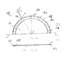
- Figure 1:
- is a schematic representation in side view of an apparatus according to the invention;
- Figure 2:
- is a partial representation of the apparatus of
Figure 1 in cross-section; - Figure 3:
- is a representation in front view of the grabbing device of the apparatus of
Figure 1 with the protective cover removed in part; - Figure 4:
- is a schematic representation in cross-section of another exemplary embodiment of the apparatus according to the invention;
- Figure 5:
- is a second representation in cross-section of the apparatus of
Figure 4 ; - Figure 6:
- is a schematic representation of the position of the circular saws between the claws;
- Figure 7:
- is a schematic representation of an alternative embodiment of the apparatus according to the invention;
- Figure 8:
- is a schematic representation in top view of the apparatus of
Figure 1 in a feed kitchen; - Figure 9:
- is a schematic representation in cross-section of a further potential embodiment of the apparatus according to the invention;
- Figure 10:
- is a representation of a longitudinal section along the line X - X in
Figure 9 ; - Figure 11:
- is a schematic representation of the apparatus of
Figure 1 with a bin of loose feed; - Figure 12:
- is a schematic representation of another potential embodiment of an apparatus according to the invention;
- Figure 13:
- is a representation of a further potential embodiment;
- Figure 14:
- is a representation of an opened grabbing device of the apparatus according to
Figure 13 ; - Figure 15:
- is a representation of the grabbing device of
Figure 14 in the closed position; - Figure 16:
- is a representation in side view of a main frame of the apparatus of
Figure 13 ; - Figure 17;
- is a representation of the main frame of
Figure 16 in rear view; - Figure 18
- is a representation in side view of the apparatus of
Figure 13 in the retracted position; - Figure 19:
- is a representation in side view of the apparatus of
Figure 13 in the extended position; - Figure 20:
- is a representation in front view of a circular saw such as used in the apparatus of
Figure 13 ; - Figure 21:
- is a representation of the circular saw of
Figure 20 in side view; - Figure 22:
- is a representation in side view of
Figure 18 with the collecting bin put in the outfeed position; - Figure 23:
- is a representation of a further potential embodiment of an apparatus according to the invention;
- Figure 24:
- is a representation of the apparatus of
Figure 23 in side view with the folding frame collapsed. -
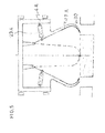
Figure 1 shows an exemplary embodiment of anapparatus 1 according to the invention for processing feed, such as loose feed or feed in the form of bales or blocks 2. Theapparatus 1 comprises a mobilemain frame 3 with asupport frame 4 which can be moved horizontally vis-'a-vis themain frame 3 by means of a roller guide 6 near the under-side of themain frame 3. Themain frame 3 is provided withswivel wheels 7. At one end themain frame 3 comprises a vertical guide 8, along which acollecting bin 9 can be moved vertically between a bottom position - shown as a continuous line inFigure 1 - and a top position - shown as a dotted line. In the top position the collecting bin can be tilted by means of a tilting guide 11. This way the collectingbin 9 can be tipped to empty it, for instance into a mixing bin or mixingrobot 12, such as shown inFigure 1 . - At the other end the
frame 3 comprises a feed pick-upzone 13, where a bale or block offeed 2 can be picked up by positioning theapparatus 1 such that thesupport frame 4 is positioned over the block or thebale 2 in question. - The
support frame 4 carries a grabbing device 14, which can be moved downwards from a resting position such as shown inFigure 1 , driven by anelectromotor 16 or similar driving mechanism arranged on top of the support frame. - The grabbing device 14 comprises two opposing rows of L-shaped
claws 17, such as shown inFigures 2 and3 . Eachclaw 17 is provided with aback plate 18 and abase plate 19 extending from the bottom edge of theback plate 18 in the direction of the opposing row ofclaws 17. At the free end the base plate comprises acutting edge 21 for cutting off a horizontal top layer of thebale 2. Theclaws 17 can be pivoted around apivot 22 between a resting position where theclaws 17 can be positioned over the top of a bale orblock 2, and a grabbing position where the cutting edges 21 of theclaws 17 penetrate into thebale 2 and cut off a top layer. InFigure 2 theclaw 17 is shown in the resting position, represented as a continuous line, while the grabbing position is represented as a dotted line. Theclaws 17 in that case are propelled individually with the aid ofhydraulic cylinders 23 under the control of a control unit (not shown). - In
Figure 3 the row ofclaws 17 is shown in the operating position in front view. If only a small quantity of feed is required, the control unit will trigger only part of theclaws 17 to cut off part of the top layer of the block or the bale. - In between the
claws 17 the grabbing device 14 comprises parallelcircular saws 24 for separating the cut-off top layer of thebale 2. After theclaws 17 have sliced off the top layer of the block or thebale 2, thecircular saws 24 saw the slice, causing it to fall apart into loose dosable feed. - An enveloping
protective cover 26 is arranged around theclaws 17 and thecircular saws 24. Theprotective cover 26 is shaped such that theclaws 17 and thecircular saws 24 can be moved in the various operating and resting positions, such as is illustrated inFigure 4 for another potential embodiment of the apparatus. - The apparatus of
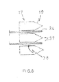
Figure 4 comprises a row ofcircular saws 24A which can be moved by means of slots between claws 17A (seeFigure 5 ). Thecircular saws 24A are capable of rotation around acommon shaft 27 and are moved with the aid of a connectingrod 28, schematically represented by means of a centre line. The connectingrod 28 comprises abottom roller guide 29, which can move along acurved bottom guide 31 in the envelopingprotective cover 26, and a top shaft 33, which can move along a vertical guide 32 positioned symmetrically above thebottom guide 31 in anarm 36 of the support frame 4A. The two outermost points of theguide 31 are in an essentially horizontal straight line. Between the outermost points theguide 31 is bent upwarts. At the top end the connectingrod 28 is driven by ahydraulic cylinder 34. Thecylinder 34 moves the top end of the connectingrod 28 back and forth, which movement is converted by means of theguides 31, 32 into a reciprocal movement of thecircular saw 24. Thehorizontal guide 31 is bent such that thecircular saws 24A are moved back and forth in a straight line Z between a first outermost position - illustrated in the drawing as the continuous line Y - and a second outermost position - illustrated in the drawing as the dotted line Y'. -
Figure 5 shows a different cross-section of the apparatus ofFigure 4 . This cross-section shows the claws 17A, which in this embodiment comprise a curved bottom end 30. The claws are hinged to suspension points 25 of the support frame 4A and can be moved in one another's direction by means of cylinders 23A. - In another potential embodiment also the
claws 17, 17A can be moved up and down by means of a vertical guide. As a result of this the last remnants of feed on the floor can be removed more easily, so that as little residual feed as possible is left on the floor. -
Figure 6 is a schematic representation of the positioning of the parallelcircular saws 24 between theclaws 17. The cutting edges 21 of thebase plates 19 are configured as triangular points 37 to allow a better penetration into the compacted feed. Thecircular saws 24 are positioned in a slot 38 between theclaws 17 in a position which is always midway between two points 37, because there the feed will concentrate when theclaws 17 are pushed along through the compacted feed. The tips of the teeth can be rounded to ensure that less feed sticks to the knives. - After the
claws 17 have cut off the top layer of a bale orblock 2, thecircular saws 24 separate the top layer into dosable feed. Theclaws 17 remain in the grabbing position and in doing so keep the separate feed together. The grabbing device 14 is put in the top position with the aid of amotor drive 16 andsteel cable 20 guided along of a pulley guide 15. Next, thesupport frame 4 driven by a hydraulic cylinder (not shown) is moved to thecollecting bin 9, which is in the top position. When thesupport frame 4 with the grabbing device 14 has been positioned above the collectingbin 9, theclaws 17 are moved apart and the separated feed falls into thecollecting bin 9. Next, thesupport frame 4 with the grabbing device 14 is returned to the original position, where thesupport frame 4 can be placed over abale 2 once again. - In addition, the
apparatus 1 is provided with weighing means, made up of weighing bars at the swivel wheels 7 (not shown). This enables the quantity of separated feed in thecollecting bin 9 and between theclaws 17 of the grabbing device 14 to be weighed precisely. The control unit can be programmed to make a continuous comparison bewteen the weighed quantity of separated feed in theapparatus 1 and a value for the required quantity of feed entered beforehand. As soon as the desired quantity has been collected, the control unit can put the grabbing device 14 in the resting position. - To empty the
collecting bin 9, theapparatus 1 can travel to themixer 12 and/or themixer 12 can be moved to theapparatus 1. The collectingbin 9 can then be tilted from the highest position to the outfeed position, where the feed from the collectingbin 9 is put in themixer 12. If so desired, the feed in themixer 12 may be mixed with further feed components. -
Figure 7 shows an alternative embodiment where thecollecting bin 9 is connected with a hingedflange 35 to a verticalhydraulic cylinder 39, which can move thecollecting bin 9 between a collecting position A (shown as a continuous line) and a high position B (shown as a dotted line). In the high position B thecollecting bin 9 can be moved over a bale or block, so that the apparatus as a whole can be positioned over a row of bales. From the low collecting position A thecollecting bin 9 can be tilted with the aid of a schematically representedsecond cylinder 40 into an unloading position C, also shown as a dotted line. This is the position in which the collecting bin is tipped to empty it, for instance into a mixer or mixingrobot 12. - On the under-side the
collecting bin 9 is provided with a boss orridge 41. A tiltinglock 42 hooks behind theridge 41 in order to prevent thecollecting bin 9 from tipping inadvertently. Using a schematically representedthird cylinder 43, thelock 42 can be tilted to one side, whereupon thecollecting bin 9 can be tipped. -
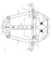
Figure 8 is a schematic representation in top view of afeed kitchen 45 in which anapparatus 1 is arranged. In thefeed kitchen 45 there are rows of bales or blocks 2 of different types, both round bales and rectangular bales or blocks. Theapparatus 1 is connected to a power cable 46 which can be rolled automatically and is pivotably connected to a suspension means. Amixer 12 can be moved on arail guide 47 or can travel across the floor. Theapparatus 1 ispositioned over afront bale 2 of the central row of rectangular bales or blocks. - Different types of feed are cut off different bales or blocks and are weighed and collected in the
collecting bin 9 of theapparatus 1 until thecollecting bin 9 contains a complete feed mixture of the desired composition. Next, theapparatus 1 travels to a station where the composition is dumped into themixer 12. If themixer 12 has not yet returned from a previous feeding alley, theapparatus 1 will await the return of themixer 12. -
Figures 9 and 10 show an alternative embodiment of an apparatus according to the invention. The embodiment is the same as the embodiment ofFigure 5 , except that the claws 17B are provided on either side withside walls 48 each provided with acutting edge 49. The cutting edges 49 connect the outermost points of the J-shaped claws 17B. This enables the claws 17B to cut through the feed themselves and no separate circular saws or other separating means are required. The cutting edges 49 are curved, so that they overlap with each other to some extent in the closed position of the claws 17B. The cutting edges can for instance be serrated or curved to prevent the crop from sliding down the cutting edges 49. -
Figure 11 is a schematic representation of theapparatus 1 ofFigure 1 with a bin orcontainer 51 disposed in the feed pick-uproom 13 beneath theclaws 17 of thesupport frame 4. Thebin 51 is filled withloose crop 52. Theclaws 17 can be moved downwards to grab the loose crop and lift it. Thesupport frame 4 can then be moved in theframe 3 to the collecting bin. Next, theclaws 17 can put the collected loose crop in thecollecting bin 9. -
Figure 12 shows a further variation wherein the claws 17C are provided with side walls 48C which are provided with a knife 55 on their free edge. By means of acrankshaft transmission 56 or driven by, for instance, a hydraulic cylinder, the knife 55 is moved up and down along the edge of the side wall 48C of the claw 17C by means of aguide 54 as the claw 17C pivots. This makes cutting the feed off easier. The cutting edge of thebase plate 19C can also be provided with such a reciprocating knife. - The apparatus further comprises
ejector plates 57, which are mounted essentially at right angles to theback plate 18C of the claw. Theejector plates 57 are connected to the support frame 4C. Theback plate 18C of the claw comprises slots (not shown) through which the ejector plates protrude. When the claw 17C is moved back and forth, theejector plates 57 slide into the interior of theclaw 17 via the slots. When unloading the feed into the collecting bin, the feed is thus ejected by the ejector plates. -
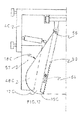
Figure 13 shows a further potential embodiment of anapparatus 100 for processing feed comprising across conveyor 101 and a mobilemain frame 102 supporting acollecting bin 103 and a grabbingdevice 104. - The grabbing
device 104 can be moved horizontally vis-'a-vis themain frame 102 by means of two parallel guide bars 106 between a first position upstream of the collecting bin 103 (such as shown inFigure 13 ), and a second position above the collectingbin 103. The ends of the guide bars are mounted on asupport frame 107. Themain frame 102 comprises twocolumns 108 along which the support frame with the grabbingdevice 104 can be moved vertically. - The grabbing device is shown in side view in
Figures 14 and15 . The grabber is provided with twosimilar grabber components 109 arranged in mirrow image, which in side view are J-shaped or L-shaped with thebottom cutting edges 112 facing one another. The twograbber components 109 each have apivot 113 and can be rotated between an open position, where the cuttingedges 112 have been moved apart (Figure 14 ), and a closed position where the cuttingedges 112 abut against one another (Figure 15 ), using ahydraulic cylinder 114 set between the twograbber components 109. - The two
grabber components 109 are provided with a row ofcircular saws 116 inside a grabbing zone 117 enclosed by thegrabber components 109. The two rows are parallel. Thecircular saws 116 have acommon drive shaft 118 for each row, which is driven by a driving gear (not shown) by means of a drive belt 119 (Figure 14 ). The circular saws of one row are positioned slightly displaced axially direction vis-'a-vis the circular saws of the other row, so that in side view thecircular saws 116 of one row, such as shown inFigure 15 , partially overlap with thecircular saws 116 of the oher row in the closed position of the grabbingdevice 104. - The two
grabber components 109 are provided with atoothed gear 121 extending from thepivot 113 in the direction of thetoothed gear 121 of theother grabber component 109. The toothed gears 121 are provided withteeth 122 of such curvature and length that the two sets ofteeth 122 mesh together as thegrabber components 109 are moved between the open position and the closed position. The movements of the twograbber components 109 are synchronised as a result. - The grabbing
device 104 comprises abase frame 123 with a slottedguide 124 for the twograbber components 109. The twograbber components 109 are provided with an arm with aroller guide 126 which can be moved in its transverse direction by means of the slottedguide 124 in question. As thegrabber components 109 are moved between the open position and the closed position, thegrabber components 109 are moved vertically by means of the respective slottedguide 124 such that the cuttingedges 112 follow an essentially horizontal path. The grabbingdevice 104 thus creates a level horizontal cutting face at the top of a bale or block and it is enabled to scrape the last remaining scraps of feed off a floor surface in an effective manner. - The grabbing
device 104 further comprises a T-shapedcentre section 127, which with its two top ends is connected to thepivots 113 of thegrabber components 109 and which by means of a vertical slotted guide 128 moves up and down with thegrabber components 109 vis-'a-vis thebase frame 123. - The floor of the
collecting bin 103 is formed by an outfeed conveyor orchain conveyor 131, which protrudes on anoutfeed side 132 of thecollecting bin 103 for some distance beyond theoutfeed bin 103. The collectingbin 103 is provided on both sides with a mountingplate 133, which at its end is provided with aroller guide 134. Thisroller guide 134 falls into avertical slot 136 in therespective column 108 of themain frame 102. By means of this vertical guide thecollecting bin 103 can be moved up and down vertically between a low collecting position, such as shown inFigure 13 , and a higher outfeed position for feeding out feed, in which process the feed in thecollecting bin 103 is fed out by theoutfeed conveyor 131, for instance into a mixing bin of mixing robot located underneath theoutfeed conveyor 131. - The two horizontal guide bars 106 for the horizontal movement of the grabbing
device 104 are supported by thesupport frame 107, which also comprises aroller guide 137 with which thesupport frame 107 can be moved up and down by means of thevertical slot 136. The twoguide bars 106 are mounted on ahead plate 138 with a top and abottom roller guide horizontal rails 142 of thesupport frame 107. This way the grabbingdevice 104 can also be moved back and forth horizontally in transverse direction in order to be aligned with a row of bales in a low position where necessary. When a bale or block is off centre, one of thegrabber components 109 will be the first to hit the bale in question as the grabbingdevice 104 closes. The grabbingdevice 104 and thehead plate 138 will then be moved sideways by means of thehorizontal rails 142 until thesecond grabber component 109 also hits the bale, whereupon the grabbing device is closed further to remove a layer of feed from the bale. Thus it is prevented that the bale is moved sideways or pushed apart as the grabbingdevice 104 closes. - When the grabbing
device 104 next is moved back upwards to the position above the collectingbin 103, the grabbingdevice 104 has to be recentred vis-'a-vis the collectingbin 103. To this end thehead plate 138 on the side facing away from the grabbingdevice 104 is provided with a roller 143 (seeFigure 17 ), which cooperates with acentring guide 144 in themain frame 102. Thecentring guide 144 is made up of twobars 146 having their top ends mounted together or side by side in the centre of themain frame 102 and which have their bottom ends mounted on the inside of thecolumns 108 of themain frame 102. When the grabbingdevice 104 is moved upwards, theroller 143 runs against thebars 146 and as a result the grabbing device with the head plate is guided to the centre by means of therails 142 and centred as it is moved upwards. - The
cross conveyor 101 comprises aplate 151 with anedge 152, which cooperates as a cross guide with afloor rail 153 in order to move theplate 151 sideways. Theplate 151 can be moved across the rail with the aid of a driving gear. - The
cross conveyor 101 further comprises a pulling element in the form of afolding frame 154 for moving themain frame 102 which is provided withwheels 156. The geared motor is mounted on thefolding frame 154. Themain frame 102 in that case can be moved between a retracted position (seeFigure 18 ), where themain frame 102 with thecollecting bin 103 is disposed on theplate 151, and an extended position (seeFigure 19 ), where themain frame 102 has been moved off theplate 151. Thefolding frame 154 comprises afirst leg 157 with a bottom end hinged to theplate 151 and a top end hinged to the top end of thesecond leg 158, which has a bottom end hinged to themain frame 102. Such a cross conveyor enables the main frame with the grabbingdevice 104 and thecollecting bin 103 to be precisely positioned in front of a row of bales or blocks. Other cross conveyors may also be used, if so desired. - When the
folding frame 154 of thecross conveyor 101 is in the retracted state, themain frame 102 with thecollecting bin 103 and the grabbingdevice 104 is disposed on theplate 151. Theplate 151 can now be moved sideways with themain frame 102 along thefloor rail 153. Themain frame 102 can thus be positioned in front of a row of bales to be processed. Thecross conveyor 101 enables precise positioning and alignment with the bales of themain frame 102, so that the centre of themain frame 102 is as fully as possible in line with the centre of the bales to be processed. - When the
main frame 102 is placed in line with the row of bales to be processed, thefolding frame 154 of thecross conveyor 101 can be extended, with themain frame 102 being pushed off theplate 151 and positioned immediately in front of the bale to be processed. Next, by means of the horizontal guide bars 106 the grabbingdevice 104 is moved to a position above the bale to be processed. The grabbingdevice 104 can now be opened.Figure 13 shows the grabbingdevice 104 in this position, albeit without a bale. - The opened grabbing
device 104 can now be lowered over a bale to a depth sufficient for removing a desired quantity of feed from the top side of the bale. Next, the grabbingdevice 104 is closed. When during the closing onegrabber component 109 hits the bale before theother grabber component 109, thefirst grabber component 109 will first pull the other one towards it before thecircular saws 106 of thegrabber component 109 penetrate into the bale. In that process the grabbingdevice 104 will be moved slightly sideways in its entirety with thehead plate 138 along the twohorizontal rails 142 in thesupport frame 139. This way thecircular saws 116 of the twograbber components 109 are enabled to penetrate into the bale simultaneously without displacing the bale. As the grabbingdevice 104 closes further, thecircular saws 116 are rotatingly driven and the feed which is between thegrabber components 109 in the grabbing zone 117 is separated. - When the grabbing
device 104 is completely closed, thebottom cutting edges 112 of the twograbber components 109 abut against one other and the grabbing zone 117 enclosed by the grabber is filled with separated feed. Now thesupport frame 107 is moved upwards with the guide bars 106 and the grabbingdevice 104. In this process theroller 143 at the back of the head plate 138 (Figure 17 ) is guided through thebars 146 of the centring guide to the centre of themain frame 102, causing the grabbingdevice 104 to be precisely re-centred vis-'a-vis themain frame 102 and thecollecting bin 103. The grabbingdevice 104 is moved backwards along the guide bars 106 until the grabbingdevice 104 is suspended above the collectingbin 103 and can be opened to dump the separated feed into thecollecting bin 103. - The grabbing
device 104 can now be moved in the same way to remove a new quantity from the same bale or from a different bale. If necessary, themain frame 102 can first be pulled onto theplate 151 of thecross conveyor 101 in order to then be positioned in front of a different row of bales or blocks. - The
main frame 102 and/or thecollecting bin 103 and/or the grabbingdevice 104 can be provided with weighing means for precise updating of the quantities of feed dosed. A user or an automated control unit is able to compare the quantities weighed with a previously entered desired composition so as to control the system on the basis of the comparative data. - When sufficient quantities of all components have been removed and the
collecting bin 103 is filled with the desired feed composition, the collectingbin 103 can be emptied. To that end themain frame 102 is pulled by thefolding frame 154 onto theplate 151. The grabbingdevice 104 is moved to the end of the guide bars 106 in order to provide room for thecollecting bin 103 which has been moved upwards. The apparatus (without the grabbing device 104) is shown in this position inFigure 22 . - If necessary, the
plate 151 with themain frame 102 and thecollecting bin 103 can be moved sideways to position the whole in front of a mixing bin or mixing robot, with the free edge of theoutfeed conveyor 131 being positioned above the mixing bin. Next, theoutfeed conveyor 131 can be put in action, with the collected feed from the collectingbin 103 being put into the mixing bin. The mixing bin can mix the feed further and transport it to a stable and dose it to the livestock present there in a conventional manner. -
Figures 20 and 21 show an individualcircular saw 116. In the shown embodiment thesaw 116 comprises a standardcircular saw blade 161 with a sawingedge 162 provided with teeth 163. The usual teeth 164 (represented as a dotted line) with saw teeth 165 are covered by aflat ring 166 with chamfered inner and outer sides 167, 168. Theflat ring 166 is connected to thesaw blade 161 withbolts 169. The tips of the saw teeth 165 are provided with cuttingedges 170, which protrude from beneath theflat ring 166 in a desired - optionally adjustable - length. Because of the teeth's short length the risk of thesaw 116 getting stuck is greatly reduced or even eliminated. The cutting edges 170 are set at a slight forward angle in the direction of rotation R, as a result of which the angle η between the extension L of thecutting edge 170 and the radial line between the centre M of the saw blade and the outermost angular tip N of the saw tooth is a sharp angle, for instance an angle of 0 - 25 degrees. - Instead of an adjusted standard saw, the saw blade of the circular saw can have been configured directly with the desired specific teeth, so that the
ring 166 is superfluous. - Another embodiment is shown in
Figure 23 . This corresponds to the embodiment ofFigure 13 , except that the version of the cross conveyor in this embodiment does not comprise a plate. Instead, the collecting bin comprises twotransverse wheels 171.Figure 23 shows thecollecting bin 103 in the low loading position, with thetransverse wheels 171 slightly higher than thewheels 156. - When the
collecting bin 104 is filled, thefolding frame 154 is retracted and themain frame 102 is positioned immediately in front of thefloor rail 153. The collectingbin 103 can then be lowered still further vis-'a-vis the main frame, in which process thetransverse wheels 171 are placed on the floor, whereupon themain frame 102 with thewheels 156 can be lifted (seeFigure 24 ). The collectingbin 103 can now be moved in transverse direction along thefloor rail 153 in order to be positioned in front of a next row of bales or blocks of feed. On the side facing away from thefolding frame 154, the collectingbin 103 comprises afront plate 105, for instance a rubber strip, which can be moved upwards by means of a transmission (not shown) when thefolding frame 154 is retracted. When the folding frame is extended, thefront plate 105 is moved downwards again, so that the plate sweeps across the floor and pushes loose feed in the direction of the bales. - The
folding frame 154 comprises atoothed segment 159, which cooperates with adriving gear 172 to have the twolegs folding frame 154 unfolds. - The
folding frame 154 can be moved along thefloor rail 153 with the aid of a driving gear. The driving gear can for instance comprise a gearedmotor 173, with achain wheel 174 mounted on the motor shaft. Over thechain wheel 174 runs a drivingchain 175, which is as long as thefloor rail 153 and connected to thefloor rail 153 at its ends by means of a tension gear. When thechain wheel 174 is driven by the motor, thefolding frame 154 is moved along the drivingchain 175. Thefolding frame 154 of the embodiment ofFigure 13 can likewise be configured with such a driving gear.
Claims (27)
- Apparatus (1; 101) for processing feed (2) comprising:- a main frame (3; 102);- a collecting bin (9; 103);- a grabbing device (14; 104) which can be moved vertically, wherein the collecting bin and the grabbing device are supported by the main frame.
- Apparatus according to claim 1, wherein the grabbing device and/or the collecting bin can be moved horizontally between a first position, where the grabber is suspended above the collecting bin, and a second position, where the grabber can be positioned above a bale or block.
- Apparatus according to claim 1 or 2, wherein the grabbing device comprises grabber components (17; 109), such as grabber components which are L-shaped or J-shaped in side view, with bottom edges (112) facing one another, wherein the two grabber components can be moved vis-'a-vis one another between an open position, where the bottom edges have been moved apart, and a closed position, where the bottom edges essentially abut against one other and the grabber components enclose a grabbing zone (117), wherein at least one of the grabber components is provided with one or more separating means (116) inside a grabbing zone enclosed by the grabber components.
- Apparatus according to claim 3, wherein the movement of the grabber components (109) between the open position and the closed position is guided along a guide (124) such that the cutting edges of the claws on the under-side move along an essentially straight horizontal surface.
- Apparatus according to any one of the preceding claims 3 or 4, wherein the separating means comprise one or more knives (116).
- Apparatus according to claim 5, wherein the knives are made up of a row of parallel circular knives or circular saws (116) on a common drive shaft (118).
- Apparatus according to claim 6, wherein the two grabber components (109) are provided with a row of parallel circular knives or circular saws (116), wherein in the closed position of the grabbing device (104) the circular saws of one row partially overlap with the circular saws of the other row in side view of the grabbing device.
- Apparatus according to any one of the preceding claims 3 - 7, wherein the two grabber components (109) can each be tilted around their own pivot (113), with the two pivots being parallel and with the two grabber components being provided with a een toothed segment (121) extending from the pivot in the direction of the toothed segment (121) of the other grabber component (109), wherein the two toothed segments (121) are provided in mirror image with teeth (122) of such curvature and length that the two sets of teeth mesh together as the grabber components move between the open position and the closed position.
- Apparatus according to any one of the preceding claims, wherein the collecting bin (103) has a bottom comprising an outfeed conveyor (131), which continues on an outfeed side of the collecting bin outside the outfeed bin.
- Apparatus according to any one of the preceding claims, wherein the collecting bin (103) can be moved, for instance tilted or lifted, from a collecting position to an outfeed position for feeding out feed.
- Apparatus according to any one of the preceding claims, wherein the grabbing device (104) when in a low position can be moved in transverse direction.
- Apparatus according to claim 10, wherein the main frame (102) is provided with a centring guide (146) for centring the grabbing device (104) by means of a horizontale guide (142) vis-'a-vis the main frame when the grabbing device is moved vertically upwards.
- Apparatus according to claim 12, provided with a brake for blocking movement along the horizontal guide (142) as the grabbing device (104) is moved downwards.
- Apparatus according to any one of the preceding claims provided with a cross conveyor (101) for moving the main frame (102) with the collecting bin (103) and the grabbing device (104) sideways.
- Apparatus according to claim 14, wherein the cross conveyor (101) comprises an essentially horizontal plate (151) which can be moved along a guide, such as a floor rail (153).
- Apparatus according to claim 14 or 15, wherein the main frame (102) is provided with wheels (156) and wherein the apparatus comprises a pulling element (154) for moving the main frame between a retracted position, where the main frame is near the floor rail (153), and an extended position, where the main frame has been moved away from the floor rail (153).
- Apparatus according to claim 16, wherein the pulling element comprises a folding frame (154), which pulls towards the floor rail (153) as the main frame (102) is retracted and pushes away from the floor rail as the main frame is extended.
- Apparatus according to claim 17, wherein the folding frame (154) comprises a first leg (157) with a bottom end which can be moved along the floor rail (153), and a top end hinged to the top end of a second leg (158), which has a bottom end hinged to the main frame (102).
- Apparatus according to any one of claims 14 - 18, wherein the cross conveyor is provided with a plate which can be moved along the floor rail (153), onto which the main frame (102) can be disposed.
- Apparatus according to any one of the preceding claims 14 - 18, wherein the main frame is provided with wheels with a direction of travel transverse to the floor rail and wherein the collecting bin is provided with wheels with a direction of travel parallel with the floor rail, wherein in a loading position of the collecting bin the wheels of the main frame are supported by the surface, while the wheels of the collecting bin are clear of the ground, wherein the collecting bin can be moved downwards to push the main frame upwards, so that the wheels of the collecting bin are supported by the surface, while the wheels of the main frame are clear of the ground.
- Apparatus according to any one of the preceding claims, wherein the main frame (102), the collecting bin (103) and/or the grabbing device (104) are provided with one or more weighing means.
- Grabber (104) for separating feed from a bale provided with two grabber components (109) with bottom edges (112) facing one another, wherein the two grabber components can be moved vis-'a-vis one another between an open position, where the bottom edges have been moved apart, and a closed position, where the bottom edges abut against one another and the grabber components enclose a grabbing zone (117), wherein at least one of the grabber components is provided with one or more separating means (116) inside a grabbing zone enclosed by the grabber components.
- Grabber according to claim 22, wherein the grabber components (109) are J-shaped or L-shaped in side view.
- Grabber according to claim 22, wherein the separating means are made up of one or more knives, for instance a row of parallel circular knives or circular saws (116) on a common drive shaft (118).
- Grabber according to claim 24, wherein the two grabber components (109) are provided with a row of parallel circular knives or circular saws (116), wherein in the closed position of the grabber the circular saws of one row partially overlap with the circular saws of the other row in side view of the grabber.
- Grabber according to any one of the preceding claims 22 - 25, wherein the two grabber components (109) can each be tilted around their own pivot (113), wherein the two pivots are parallel and wherein the two grabber components are provided with a toothed segment (121) extending from the pivot in the direction of the toothed segment of the other grabber component, wherein the two toothed segments are provided in mirror image with teeth (122) of such curvature and length that the two sets of teeth mesh together as the grabber components are moved between the open position and the closed position.
- Grabber according to any one of the preceding claims 22 - 26, wherein the grabber (104) comprises a frame (123) with a slotted guide (124) for the two grabber components (109) along which the grabber components are moved up and down as the grabber is moved between the open position and the closed position, such that the cutting edges (112) follow an essentially horizontal path.
Priority Applications (1)
| Application Number | Priority Date | Filing Date | Title |
|---|---|---|---|
| EP14187355.4A EP2820942B1 (en) | 2013-03-28 | 2014-03-28 | Grabber for separating feed for livestock |
Applications Claiming Priority (2)
| Application Number | Priority Date | Filing Date | Title |
|---|---|---|---|
| NL2010541A NL2010541C2 (en) | 2013-03-28 | 2013-03-28 | DEVICE FOR PROCESSING FEED. |
| NL2011357A NL2011357C2 (en) | 2013-03-28 | 2013-08-29 | DEVICE FOR PROCESSING FEED. |
Related Child Applications (2)
| Application Number | Title | Priority Date | Filing Date |
|---|---|---|---|
| EP14187355.4A Division-Into EP2820942B1 (en) | 2013-03-28 | 2014-03-28 | Grabber for separating feed for livestock |
| EP14187355.4A Division EP2820942B1 (en) | 2013-03-28 | 2014-03-28 | Grabber for separating feed for livestock |
Publications (4)
| Publication Number | Publication Date |
|---|---|
| EP2783567A2 true EP2783567A2 (en) | 2014-10-01 |
| EP2783567A3 EP2783567A3 (en) | 2014-12-17 |
| EP2783567B1 EP2783567B1 (en) | 2017-03-08 |
| EP2783567B8 EP2783567B8 (en) | 2017-08-02 |
Family
ID=50389323
Family Applications (2)
| Application Number | Title | Priority Date | Filing Date |
|---|---|---|---|
| EP14187355.4A Revoked EP2820942B1 (en) | 2013-03-28 | 2014-03-28 | Grabber for separating feed for livestock |
| EP14162382.7A Not-in-force EP2783567B8 (en) | 2013-03-28 | 2014-03-28 | Device for processing fodder |
Family Applications Before (1)
| Application Number | Title | Priority Date | Filing Date |
|---|---|---|---|
| EP14187355.4A Revoked EP2820942B1 (en) | 2013-03-28 | 2014-03-28 | Grabber for separating feed for livestock |
Country Status (2)
| Country | Link |
|---|---|
| EP (2) | EP2820942B1 (en) |
| NL (1) | NL2011357C2 (en) |
Cited By (2)
| Publication number | Priority date | Publication date | Assignee | Title |
|---|---|---|---|---|
| CN104760073A (en) * | 2015-04-10 | 2015-07-08 | 有友食品股份有限公司 | Transmission mechanism for chicken feet cutting machine |
| EP3491909A1 (en) * | 2017-12-04 | 2019-06-05 | Triodor Arge | Bucket grabber for grabbing feed, attachable and detachable cutting device for a bucket grabber, automatic feeding system for farm animals provided with the bucket grabber |
Citations (1)
| Publication number | Priority date | Publication date | Assignee | Title |
|---|---|---|---|---|
| DE3101350A1 (en) | 1981-01-17 | 1982-11-04 | B. Strautmann & Söhne GmbH u. Co, 4518 Bad Laer | Device for cutting off silage blocks |
Family Cites Families (26)
| Publication number | Priority date | Publication date | Assignee | Title |
|---|---|---|---|---|
| US938338A (en) * | 1909-02-08 | 1909-10-26 | Joshua B Rickards | Dredging-bucket. |
| US2176921A (en) * | 1938-03-14 | 1939-10-24 | Samuel G Neff | Grapple jet device |
| US2571502A (en) | 1949-06-24 | 1951-10-16 | Lyle R Uhland | Foliage removal bucket |
| GB729501A (en) | 1952-11-27 | 1955-05-04 | Priestman Brothers | Improvements relating to grabs |
| US3038620A (en) | 1960-09-09 | 1962-06-12 | Raymond H Collin | Rotatable pick-up and deposit device |
| DE2415664A1 (en) * | 1974-04-01 | 1975-10-16 | Krupp Gmbh | METHOD OF OPERATING A GRIPPER FOR BULK GOODS AND GRIPPERS |
| DE2611648A1 (en) * | 1976-03-19 | 1977-09-22 | Max Hagmeyer | Silage extractor for tall silos - has cable and pulley operated grab with two side tines with facing cutter blades |
| BE863397A (en) * | 1978-01-27 | 1978-05-16 | Thomas Joris J | GRIPPER FOR LIFTING GEAR AND CUTTING MECHANISM USED WITH IT |
| DE3510401A1 (en) * | 1985-03-22 | 1986-09-25 | Klaus-Peter 4518 Bad Laer Strautmann | Silo-bale distributor |
| DE3815229A1 (en) * | 1988-05-05 | 1989-11-16 | Strautmann & Soehne | Feed mixing vehicle |
| US5193873A (en) | 1989-12-15 | 1993-03-16 | Centro De Investigacion Y. Asistencia Tecnica Del Estado De Queretaro, A.C. | Sugar cane grab |
| NL9100384A (en) | 1991-03-01 | 1992-10-01 | Trioliet Mullos | REMOVAL DISTRIBUTION DEVICE FOR SILAGE MATERIAL. |
| GB9307753D0 (en) | 1993-04-15 | 1993-06-02 | Taylor William | Bucket based silage block cutter |
| DE4327864A1 (en) * | 1993-08-19 | 1995-02-23 | Von Der Thomas Saal | Mixing gripper for composting installations |
| NL193828C (en) | 1994-03-22 | 2000-12-04 | Bos & Kalis Baggermaatsch | Gripper with horizontal path of cutting edges. |
| NL1000659C1 (en) | 1995-06-26 | 1996-12-31 | Oord Acz B V Van | Scoop type material lifting unit |
| DE29615434U1 (en) | 1996-09-05 | 1996-11-28 | Strautmann & Soehne | Gripping bucket for removing silage from flat silos |
| US6126216A (en) * | 1999-12-01 | 2000-10-03 | Tollefson; James S. | Bucket attachment for log grapple |
| US6347464B1 (en) * | 1999-12-29 | 2002-02-19 | Gene Klager | Self-cleaning hydraulic clam bucket |
| DE20104426U1 (en) | 2001-03-14 | 2001-05-23 | Trioliet Mullos | Silage cutting pliers |
| NL1022678C2 (en) | 2003-02-14 | 2004-08-17 | Trioliet Mullos | Method and device for retrieving a quantity of feed from a feed supply. |
| EP1516530A1 (en) * | 2003-09-22 | 2005-03-23 | Mullos B.V. Trioliet | Movable apparatus for mixing fodder |
| FR2874477A1 (en) | 2004-08-31 | 2006-03-03 | Mb Nutrimel Entpr Unipersonnel | Product e.g. fodder, mixing and dispensing machine for e.g. livestock feeding, has chassis extending outside by platform, and loading device including cup lifting apparatus to remove product doses and to pour them inside case |
| NL1033349C2 (en) * | 2007-02-06 | 2008-08-07 | Maasland Nv | Feed wagon for feeding animals such as cows. |
| NL1033589C2 (en) * | 2007-03-26 | 2008-09-29 | Maasland Nv | Assembly of a milking robot with a milking robot feeding place, and device for gripping and moving material. |
| NL1036244C2 (en) * | 2008-11-26 | 2010-05-27 | Lely Patent Nv | FEED TRANSACTION DEVICE AND A COMPOSITION THEREOF. |
-
2013
- 2013-08-29 NL NL2011357A patent/NL2011357C2/en not_active IP Right Cessation
-
2014
- 2014-03-28 EP EP14187355.4A patent/EP2820942B1/en not_active Revoked
- 2014-03-28 EP EP14162382.7A patent/EP2783567B8/en not_active Not-in-force
Patent Citations (1)
| Publication number | Priority date | Publication date | Assignee | Title |
|---|---|---|---|---|
| DE3101350A1 (en) | 1981-01-17 | 1982-11-04 | B. Strautmann & Söhne GmbH u. Co, 4518 Bad Laer | Device for cutting off silage blocks |
Non-Patent Citations (1)
| Title |
|---|
| G. ZEVENBERGEN: "Lely voedt automatisch", June 2012, VEEHOUDERIJ TECHNIEK |
Cited By (3)
| Publication number | Priority date | Publication date | Assignee | Title |
|---|---|---|---|---|
| CN104760073A (en) * | 2015-04-10 | 2015-07-08 | 有友食品股份有限公司 | Transmission mechanism for chicken feet cutting machine |
| EP3491909A1 (en) * | 2017-12-04 | 2019-06-05 | Triodor Arge | Bucket grabber for grabbing feed, attachable and detachable cutting device for a bucket grabber, automatic feeding system for farm animals provided with the bucket grabber |
| NL2020010B1 (en) * | 2017-12-04 | 2019-06-11 | Triodor Arge | Bucket grabber for grabbing feed, attachable and detachable cutting device for a bucket grabber, automatic feeding system for farm animals provided with the bucket grabber and method of cutting a bale of feed using a bucket grabber's closing force |
Also Published As
| Publication number | Publication date |
|---|---|
| EP2783567B1 (en) | 2017-03-08 |
| EP2783567A3 (en) | 2014-12-17 |
| EP2820942B1 (en) | 2017-02-15 |
| EP2820942A2 (en) | 2015-01-07 |
| NL2011357C2 (en) | 2014-09-30 |
| EP2820942A3 (en) | 2015-03-11 |
| EP2783567B8 (en) | 2017-08-02 |
Similar Documents
| Publication | Publication Date | Title |
|---|---|---|
| US4597703A (en) | Bale handling and hay distributing apparatus | |
| US4711403A (en) | Method and apparatus for cleaning chicken manure from chicken houses | |
| US4420119A (en) | Horizontal silage unloader | |
| US10674675B2 (en) | Processing of blocks or bales of feed | |
| US3873032A (en) | Material feeding apparatus | |
| EP2783567B1 (en) | Device for processing fodder | |
| US4187990A (en) | Metering stack feeder and methods | |
| DE3112743A1 (en) | Apparatus for the supplying and discharging of animal feed | |
| CS207359B2 (en) | Facility for separating the sappy fodder,for lifting the separated block of fooder and for transport thereof for the desired place | |
| IE54509B1 (en) | Pickup/spreader vehicle for silage, straw and similar material | |
| EP2567609B1 (en) | Device for removing feed from flat silos | |
| EP0954220B1 (en) | Shredding apparatus with tiltable loading mechanism | |
| US4052011A (en) | Combination stack mover and processor | |
| EP0046718B1 (en) | Trailer for loading, mixing and delivering silage | |
| DE3235781C2 (en) | ||
| CN110775384A (en) | Automatic bag cutting device | |
| DE1431839C3 (en) | ||
| NL2010541C2 (en) | DEVICE FOR PROCESSING FEED. | |
| CN212829568U (en) | Automatic bag cutting device | |
| DK2826359T3 (en) | Self-filling feed mixer wagon comprising a filling device | |
| CN217256685U (en) | Tail dish feeding device | |
| RU28423U1 (en) | Feed chopper | |
| RU75534U1 (en) | DEVICE FOR CUTTING ROLLS OF SENAGE | |
| RU56775U1 (en) | FEED GRINDER | |
| RU1828393C (en) | Method of processing feed mixture and mobile feed processing unit |
Legal Events
| Date | Code | Title | Description |
|---|---|---|---|
| 17P | Request for examination filed |
Effective date: 20140328 |
|
| AK | Designated contracting states |
Kind code of ref document: A2 Designated state(s): AL AT BE BG CH CY CZ DE DK EE ES FI FR GB GR HR HU IE IS IT LI LT LU LV MC MK MT NL NO PL PT RO RS SE SI SK SM TR |
|
| AX | Request for extension of the european patent |
Extension state: BA ME |
|
| PUAI | Public reference made under article 153(3) epc to a published international application that has entered the european phase |
Free format text: ORIGINAL CODE: 0009012 |
|
| PUAL | Search report despatched |
Free format text: ORIGINAL CODE: 0009013 |
|
| AK | Designated contracting states |
Kind code of ref document: A3 Designated state(s): AL AT BE BG CH CY CZ DE DK EE ES FI FR GB GR HR HU IE IS IT LI LT LU LV MC MK MT NL NO PL PT RO RS SE SI SK SM TR |
|
| AX | Request for extension of the european patent |
Extension state: BA ME |
|
| RIC1 | Information provided on ipc code assigned before grant |
Ipc: B66C 3/04 20060101ALI20141107BHEP Ipc: A01K 5/02 20060101ALI20141107BHEP Ipc: A01F 25/20 20060101ALI20141107BHEP Ipc: A01K 5/00 20060101AFI20141107BHEP |
|
| R17P | Request for examination filed (corrected) |
Effective date: 20150617 |
|
| RBV | Designated contracting states (corrected) |
Designated state(s): AL AT BE BG CH CY CZ DE DK EE ES FI FR GB GR HR HU IE IS IT LI LT LU LV MC MK MT NL NO PL PT RO RS SE SI SK SM TR |
|
| 17Q | First examination report despatched |
Effective date: 20151222 |
|
| RIC1 | Information provided on ipc code assigned before grant |
Ipc: A01K 5/02 20060101ALI20160808BHEP Ipc: B66C 3/04 20060101ALI20160808BHEP Ipc: A01K 5/00 20060101AFI20160808BHEP Ipc: A01F 29/00 20060101ALI20160808BHEP Ipc: A01F 25/20 20060101ALI20160808BHEP |
|
| GRAP | Despatch of communication of intention to grant a patent |
Free format text: ORIGINAL CODE: EPIDOSNIGR1 |
|
| INTG | Intention to grant announced |
Effective date: 20161014 |
|
| GRAS | Grant fee paid |
Free format text: ORIGINAL CODE: EPIDOSNIGR3 |
|
| GRAA | (expected) grant |
Free format text: ORIGINAL CODE: 0009210 |
|
| AK | Designated contracting states |
Kind code of ref document: B1 Designated state(s): AL AT BE BG CH CY CZ DE DK EE ES FI FR GB GR HR HU IE IS IT LI LT LU LV MC MK MT NL NO PL PT RO RS SE SI SK SM TR |
|
| REG | Reference to a national code |
Ref country code: GB Ref legal event code: FG4D |
|
| REG | Reference to a national code |
Ref country code: CH Ref legal event code: EP Ref country code: AT Ref legal event code: REF Ref document number: 872691 Country of ref document: AT Kind code of ref document: T Effective date: 20170315 |
|
| REG | Reference to a national code |
Ref country code: IE Ref legal event code: FG4D |
|
| REG | Reference to a national code |
Ref country code: DE Ref legal event code: R096 Ref document number: 602014007285 Country of ref document: DE |
|
| REG | Reference to a national code |
Ref country code: FR Ref legal event code: PLFP Year of fee payment: 4 |
|
| GRAT | Correction requested after decision to grant or after decision to maintain patent in amended form |
Free format text: ORIGINAL CODE: EPIDOSNCDEC |
|
| REG | Reference to a national code |
Ref country code: NL Ref legal event code: FP |
|
| RAP2 | Party data changed (patent owner data changed or rights of a patent transferred) |
Owner name: LIET, CORNELIS HENDRICUS |
|
| RIN2 | Information on inventor provided after grant (corrected) |
Inventor name: LIET, CORNELIS HENDRICUS |
|
| REG | Reference to a national code |
Ref country code: LT Ref legal event code: MG4D |
|
| PG25 | Lapsed in a contracting state [announced via postgrant information from national office to epo] |
Ref country code: FI Free format text: LAPSE BECAUSE OF FAILURE TO SUBMIT A TRANSLATION OF THE DESCRIPTION OR TO PAY THE FEE WITHIN THE PRESCRIBED TIME-LIMIT Effective date: 20170308 Ref country code: LT Free format text: LAPSE BECAUSE OF FAILURE TO SUBMIT A TRANSLATION OF THE DESCRIPTION OR TO PAY THE FEE WITHIN THE PRESCRIBED TIME-LIMIT Effective date: 20170308 Ref country code: HR Free format text: LAPSE BECAUSE OF FAILURE TO SUBMIT A TRANSLATION OF THE DESCRIPTION OR TO PAY THE FEE WITHIN THE PRESCRIBED TIME-LIMIT Effective date: 20170308 Ref country code: NO Free format text: LAPSE BECAUSE OF FAILURE TO SUBMIT A TRANSLATION OF THE DESCRIPTION OR TO PAY THE FEE WITHIN THE PRESCRIBED TIME-LIMIT Effective date: 20170608 Ref country code: GR Free format text: LAPSE BECAUSE OF FAILURE TO SUBMIT A TRANSLATION OF THE DESCRIPTION OR TO PAY THE FEE WITHIN THE PRESCRIBED TIME-LIMIT Effective date: 20170609 |
|
| REG | Reference to a national code |
Ref country code: DE Ref legal event code: R081 Ref document number: 602014007285 Country of ref document: DE Owner name: TRIOLIET HOLDING B.V., NL Free format text: FORMER OWNER: LIET, LOSSER, NL |
|
| REG | Reference to a national code |
Ref country code: AT Ref legal event code: MK05 Ref document number: 872691 Country of ref document: AT Kind code of ref document: T Effective date: 20170308 |
|
| PG25 | Lapsed in a contracting state [announced via postgrant information from national office to epo] |
Ref country code: LV Free format text: LAPSE BECAUSE OF FAILURE TO SUBMIT A TRANSLATION OF THE DESCRIPTION OR TO PAY THE FEE WITHIN THE PRESCRIBED TIME-LIMIT Effective date: 20170308 Ref country code: ES Free format text: LAPSE BECAUSE OF FAILURE TO SUBMIT A TRANSLATION OF THE DESCRIPTION OR TO PAY THE FEE WITHIN THE PRESCRIBED TIME-LIMIT Effective date: 20170308 Ref country code: RS Free format text: LAPSE BECAUSE OF FAILURE TO SUBMIT A TRANSLATION OF THE DESCRIPTION OR TO PAY THE FEE WITHIN THE PRESCRIBED TIME-LIMIT Effective date: 20170308 Ref country code: BG Free format text: LAPSE BECAUSE OF FAILURE TO SUBMIT A TRANSLATION OF THE DESCRIPTION OR TO PAY THE FEE WITHIN THE PRESCRIBED TIME-LIMIT Effective date: 20170608 Ref country code: SE Free format text: LAPSE BECAUSE OF FAILURE TO SUBMIT A TRANSLATION OF THE DESCRIPTION OR TO PAY THE FEE WITHIN THE PRESCRIBED TIME-LIMIT Effective date: 20170308 |
|
| PG25 | Lapsed in a contracting state [announced via postgrant information from national office to epo] |
Ref country code: SK Free format text: LAPSE BECAUSE OF FAILURE TO SUBMIT A TRANSLATION OF THE DESCRIPTION OR TO PAY THE FEE WITHIN THE PRESCRIBED TIME-LIMIT Effective date: 20170308 Ref country code: EE Free format text: LAPSE BECAUSE OF FAILURE TO SUBMIT A TRANSLATION OF THE DESCRIPTION OR TO PAY THE FEE WITHIN THE PRESCRIBED TIME-LIMIT Effective date: 20170308 Ref country code: RO Free format text: LAPSE BECAUSE OF FAILURE TO SUBMIT A TRANSLATION OF THE DESCRIPTION OR TO PAY THE FEE WITHIN THE PRESCRIBED TIME-LIMIT Effective date: 20170308 Ref country code: AT Free format text: LAPSE BECAUSE OF FAILURE TO SUBMIT A TRANSLATION OF THE DESCRIPTION OR TO PAY THE FEE WITHIN THE PRESCRIBED TIME-LIMIT Effective date: 20170308 Ref country code: CZ Free format text: LAPSE BECAUSE OF FAILURE TO SUBMIT A TRANSLATION OF THE DESCRIPTION OR TO PAY THE FEE WITHIN THE PRESCRIBED TIME-LIMIT Effective date: 20170308 Ref country code: IT Free format text: LAPSE BECAUSE OF FAILURE TO SUBMIT A TRANSLATION OF THE DESCRIPTION OR TO PAY THE FEE WITHIN THE PRESCRIBED TIME-LIMIT Effective date: 20170308 |
|
| REG | Reference to a national code |
Ref country code: CH Ref legal event code: PL |
|
| REG | Reference to a national code |
Ref country code: DE Ref legal event code: R081 Ref document number: 602014007285 Country of ref document: DE Owner name: TRIOLIET HOLDING B.V., NL Free format text: FORMER OWNER: LIET, CORNELIS HENDRICUS, LOSSER, NL |
|
| RAP2 | Party data changed (patent owner data changed or rights of a patent transferred) |
Owner name: TRIOLIET HOLDING B.V. |
|
| RIN2 | Information on inventor provided after grant (corrected) |
Inventor name: LIET, CORNELIS HENDRICUS |
|
| PG25 | Lapsed in a contracting state [announced via postgrant information from national office to epo] |
Ref country code: PL Free format text: LAPSE BECAUSE OF FAILURE TO SUBMIT A TRANSLATION OF THE DESCRIPTION OR TO PAY THE FEE WITHIN THE PRESCRIBED TIME-LIMIT Effective date: 20170308 Ref country code: PT Free format text: LAPSE BECAUSE OF FAILURE TO SUBMIT A TRANSLATION OF THE DESCRIPTION OR TO PAY THE FEE WITHIN THE PRESCRIBED TIME-LIMIT Effective date: 20170710 Ref country code: IS Free format text: LAPSE BECAUSE OF FAILURE TO SUBMIT A TRANSLATION OF THE DESCRIPTION OR TO PAY THE FEE WITHIN THE PRESCRIBED TIME-LIMIT Effective date: 20170708 Ref country code: SM Free format text: LAPSE BECAUSE OF FAILURE TO SUBMIT A TRANSLATION OF THE DESCRIPTION OR TO PAY THE FEE WITHIN THE PRESCRIBED TIME-LIMIT Effective date: 20170308 |
|
| REG | Reference to a national code |
Ref country code: NL Ref legal event code: PD Owner name: TRIOLIET HOLDING B.V.; NL Free format text: DETAILS ASSIGNMENT: CHANGE OF OWNER(S), ASSIGNMENT; FORMER OWNER NAME: LIET Effective date: 20171031 |
|
| REG | Reference to a national code |
Ref country code: DE Ref legal event code: R097 Ref document number: 602014007285 Country of ref document: DE |
|
| REG | Reference to a national code |
Ref country code: IE Ref legal event code: MM4A |
|
| PLBE | No opposition filed within time limit |
Free format text: ORIGINAL CODE: 0009261 |
|
| STAA | Information on the status of an ep patent application or granted ep patent |
Free format text: STATUS: NO OPPOSITION FILED WITHIN TIME LIMIT |
|
| PG25 | Lapsed in a contracting state [announced via postgrant information from national office to epo] |
Ref country code: MC Free format text: LAPSE BECAUSE OF FAILURE TO SUBMIT A TRANSLATION OF THE DESCRIPTION OR TO PAY THE FEE WITHIN THE PRESCRIBED TIME-LIMIT Effective date: 20170308 Ref country code: DK Free format text: LAPSE BECAUSE OF FAILURE TO SUBMIT A TRANSLATION OF THE DESCRIPTION OR TO PAY THE FEE WITHIN THE PRESCRIBED TIME-LIMIT Effective date: 20170308 Ref country code: LU Free format text: LAPSE BECAUSE OF NON-PAYMENT OF DUE FEES Effective date: 20170328 |
|
| 26N | No opposition filed |
Effective date: 20171211 |
|
| PG25 | Lapsed in a contracting state [announced via postgrant information from national office to epo] |
Ref country code: CH Free format text: LAPSE BECAUSE OF NON-PAYMENT OF DUE FEES Effective date: 20170331 Ref country code: SI Free format text: LAPSE BECAUSE OF FAILURE TO SUBMIT A TRANSLATION OF THE DESCRIPTION OR TO PAY THE FEE WITHIN THE PRESCRIBED TIME-LIMIT Effective date: 20170308 Ref country code: IE Free format text: LAPSE BECAUSE OF NON-PAYMENT OF DUE FEES Effective date: 20170328 Ref country code: LI Free format text: LAPSE BECAUSE OF NON-PAYMENT OF DUE FEES Effective date: 20170331 |
|
| REG | Reference to a national code |
Ref country code: BE Ref legal event code: MM Effective date: 20170331 |
|
| REG | Reference to a national code |
Ref country code: FR Ref legal event code: PLFP Year of fee payment: 5 |
|
| PGFP | Annual fee paid to national office [announced via postgrant information from national office to epo] |
Ref country code: NL Payment date: 20180328 Year of fee payment: 5 |
|
| PG25 | Lapsed in a contracting state [announced via postgrant information from national office to epo] |
Ref country code: BE Free format text: LAPSE BECAUSE OF NON-PAYMENT OF DUE FEES Effective date: 20170331 |
|
| PGFP | Annual fee paid to national office [announced via postgrant information from national office to epo] |
Ref country code: FR Payment date: 20180326 Year of fee payment: 5 |
|
| PGFP | Annual fee paid to national office [announced via postgrant information from national office to epo] |
Ref country code: DE Payment date: 20180328 Year of fee payment: 5 |
|
| PG25 | Lapsed in a contracting state [announced via postgrant information from national office to epo] |
Ref country code: MT Free format text: LAPSE BECAUSE OF NON-PAYMENT OF DUE FEES Effective date: 20170328 |
|
| GBPC | Gb: european patent ceased through non-payment of renewal fee |
Effective date: 20180328 |
|
| PG25 | Lapsed in a contracting state [announced via postgrant information from national office to epo] |
Ref country code: GB Free format text: LAPSE BECAUSE OF NON-PAYMENT OF DUE FEES Effective date: 20180328 |
|
| PG25 | Lapsed in a contracting state [announced via postgrant information from national office to epo] |
Ref country code: HU Free format text: LAPSE BECAUSE OF FAILURE TO SUBMIT A TRANSLATION OF THE DESCRIPTION OR TO PAY THE FEE WITHIN THE PRESCRIBED TIME-LIMIT; INVALID AB INITIO Effective date: 20140328 |
|
| REG | Reference to a national code |
Ref country code: DE Ref legal event code: R119 Ref document number: 602014007285 Country of ref document: DE |
|
| PG25 | Lapsed in a contracting state [announced via postgrant information from national office to epo] |
Ref country code: CY Free format text: LAPSE BECAUSE OF NON-PAYMENT OF DUE FEES Effective date: 20170308 |
|
| REG | Reference to a national code |
Ref country code: NL Ref legal event code: MM Effective date: 20190401 |
|
| PG25 | Lapsed in a contracting state [announced via postgrant information from national office to epo] |
Ref country code: MK Free format text: LAPSE BECAUSE OF FAILURE TO SUBMIT A TRANSLATION OF THE DESCRIPTION OR TO PAY THE FEE WITHIN THE PRESCRIBED TIME-LIMIT Effective date: 20170308 |
|
| PG25 | Lapsed in a contracting state [announced via postgrant information from national office to epo] |
Ref country code: NL Free format text: LAPSE BECAUSE OF NON-PAYMENT OF DUE FEES Effective date: 20190401 Ref country code: DE Free format text: LAPSE BECAUSE OF NON-PAYMENT OF DUE FEES Effective date: 20191001 |
|
| PG25 | Lapsed in a contracting state [announced via postgrant information from national office to epo] |
Ref country code: FR Free format text: LAPSE BECAUSE OF NON-PAYMENT OF DUE FEES Effective date: 20190331 |
|
| PG25 | Lapsed in a contracting state [announced via postgrant information from national office to epo] |
Ref country code: TR Free format text: LAPSE BECAUSE OF FAILURE TO SUBMIT A TRANSLATION OF THE DESCRIPTION OR TO PAY THE FEE WITHIN THE PRESCRIBED TIME-LIMIT Effective date: 20170308 |
|
| PG25 | Lapsed in a contracting state [announced via postgrant information from national office to epo] |
Ref country code: AL Free format text: LAPSE BECAUSE OF FAILURE TO SUBMIT A TRANSLATION OF THE DESCRIPTION OR TO PAY THE FEE WITHIN THE PRESCRIBED TIME-LIMIT Effective date: 20170308 |