EP2820942B1 - Grabber for separating feed for livestock - Google Patents
Grabber for separating feed for livestock Download PDFInfo
- Publication number
- EP2820942B1 EP2820942B1 EP14187355.4A EP14187355A EP2820942B1 EP 2820942 B1 EP2820942 B1 EP 2820942B1 EP 14187355 A EP14187355 A EP 14187355A EP 2820942 B1 EP2820942 B1 EP 2820942B1
- Authority
- EP
- European Patent Office
- Prior art keywords
- claws
- grabber
- feed
- moved
- collecting bin
- Prior art date
- Legal status (The legal status is an assumption and is not a legal conclusion. Google has not performed a legal analysis and makes no representation as to the accuracy of the status listed.)
- Revoked
Links
Images


Classifications
-
- A—HUMAN NECESSITIES
- A01—AGRICULTURE; FORESTRY; ANIMAL HUSBANDRY; HUNTING; TRAPPING; FISHING
- A01K—ANIMAL HUSBANDRY; CARE OF BIRDS, FISHES, INSECTS; FISHING; REARING OR BREEDING ANIMALS, NOT OTHERWISE PROVIDED FOR; NEW BREEDS OF ANIMALS
- A01K5/00—Feeding devices for stock or game ; Feeding wagons; Feeding stacks
- A01K5/001—Fodder distributors with mixer or shredder
-
- A—HUMAN NECESSITIES
- A01—AGRICULTURE; FORESTRY; ANIMAL HUSBANDRY; HUNTING; TRAPPING; FISHING
- A01F—PROCESSING OF HARVESTED PRODUCE; HAY OR STRAW PRESSES; DEVICES FOR STORING AGRICULTURAL OR HORTICULTURAL PRODUCE
- A01F29/00—Cutting apparatus specially adapted for cutting hay, straw or the like
- A01F29/005—Cutting apparatus specially adapted for cutting hay, straw or the like for disintegrating and cutting up bales of hay, straw or fodder
-
- A—HUMAN NECESSITIES
- A01—AGRICULTURE; FORESTRY; ANIMAL HUSBANDRY; HUNTING; TRAPPING; FISHING
- A01K—ANIMAL HUSBANDRY; CARE OF BIRDS, FISHES, INSECTS; FISHING; REARING OR BREEDING ANIMALS, NOT OTHERWISE PROVIDED FOR; NEW BREEDS OF ANIMALS
- A01K5/00—Feeding devices for stock or game ; Feeding wagons; Feeding stacks
- A01K5/02—Automatic devices
- A01K5/0266—Automatic devices with stable trolleys, e.g. suspended
-
- B—PERFORMING OPERATIONS; TRANSPORTING
- B66—HOISTING; LIFTING; HAULING
- B66C—CRANES; LOAD-ENGAGING ELEMENTS OR DEVICES FOR CRANES, CAPSTANS, WINCHES, OR TACKLES
- B66C3/00—Load-engaging elements or devices attached to lifting or lowering gear of cranes or adapted for connection therewith and intended primarily for transmitting lifting forces to loose materials; Grabs
- B66C3/04—Tine grabs
Definitions
- the invention relates to a grabber for separating feed for livestock.
- Feed such as silage
- Cut silage compacted in a silage pit is usually referred to as "blocks", while feed compacted in a baling press is usually referred to as "bales”.
- blocks Cut silage compacted in a baling press
- baling press feed compacted in a baling press
- Vector® Lely voedt réelle
- This system involves blocks of feed being deposited in a feed kitchen. A grabber grabs feed from a block to put it in a mixing carriage. In the mixing carriage the feed, originating from different blocks, is mixed and conveyed to the livestock to be fed. For each quantity of separated feed the grabber has to be moved back and forth to the mixer. This has to be done at a moderate speed in order to prevent the suspended grabber from swinging.
- the mixer convey the feed to a feeding alley. Hence a lot of time is needed to mix the feed from the bales and convey it to the feeding alley.
- the grabber is comparatively heavy and impossible to control precisely and for instance can easily land on the bale at an angle, as a result of which the bale can be damaged and partially fall apart.
- the quantity of material grabbed by the grabber cannot be dosed precisely.
- the space between the grabber and the mixer varies. Starting, slowing down and positioning the grabber takes up a lot of time.
- Separating feed from a bale or block should be done in such a way that the structure of the remaining part of the block or bale remains intact and does not break off in order to prevent oxygen from intruding in the bale and setting decomposition processes in motion.
- Using a grabber can cause the blocks to break and fall apart, as a result of which the remaining feed will decompose more quickly. Also, such a grabber makes precise dosing impossible.
- feed will fall from the grabber when it is moved to the mixing carriage. Nor is the grabber able to properly pick the last remnants of the block off the floor. Feed remnants left behind may start to ferment and accelerate the spoiling of the other feed in the feed kitchen. Because of this the feed kitchen will need to be cleaned and restocked on a regular basis.
- US 6,126,216 discloses a bucket comprising a pair of two opposed grabbing elements. Such grabbers do not enable separating accurately dosed portions from baled feed. The same holds for the grabber disclosed in NL 7503185 , which is typically used for loose bulk material.
- BE 863 397 A2 discloses a grabber with grabbing teeth and vertical side plates provided with knives. A further teethed grabber is disclosed by DE 26 11 648 A1 .
- DE 43 27 864 A1 discloses a mixing gripper with a lower side formed by rows of milling cutters.
- the present invention has for its object to provide a grabber which will enable collection of feed, for instance from blocks or bales or loose feed, efficiently and quickly, as well as precise dosing thereof.
- the object of the invention is attained with a grabber according to claim 1, which makes it possible to separate accurately dosed portions of baled feed.
- the grabber may be part of an apparatus for processing feed comprising:
- the grabber and/or the collecting bin can be moved horizontally between a first position, where the grabber is placed above the collecting bin, and a second position, where the grabber can be positioned above a bale or block.
- the grabbing device can be moved downwards to separate feed from the top of the bale or the block.
- the support frame with the grabbing device can be moved to the position above the collecting bin to then put the separated feed in the collecting bin.
- the support frame with the grabbing device can be repositioned above the feed pick-up zone in order to remove more feed from the same block or bale, or from a new block or bale or, optionally, from a stock of uncompacted feed.
- the collecting bin can be emptied into a mixer.
- the contents of the collecting bin are essentially the same as those in the mixer, so that the collecting bin is able to fill the mixer in one go.
- the collecting bin can be refilled at the same time. Because the mixer and the collecting bin can be used simultaneously, the system's capacity is doubled.
- the grabbing device can be moved back and forth more rapidly between the bale and the collecting bin than in the case of grabbers from older systems. After the collecting bin has been emptied into the mixer, the grabbing device can continue straightaway with separating feed, without having to wait for the return of the mixer, which also brings time savings.
- the collecting bin can for instance be moved, for instance tilted, into an outfeed position for feeding out feed.
- the feed can thus be put into a mixing bin, such as a stationary mixer or a mixing robot, or onto an outfeed conveyor or similar outfeeding means. In this process the feed can for instance be mixed with other feed components.
- the apparatus can for instance be configured such that the collecting bin can be moved vertically by means of a vertical guide between a bottom position and a top position, in which process the collecting bin when in the top position can be tilted into the outfeed position.
- the collecting bin can be placed low down, so that even in low positions, when the bale or the block is nearly finished, the grabbing device is still able to put the separated feed in the collecting bin.
- the grabbing device can comprise separating means, such as one or more saws or milling rollers, for separating the cut-off top layer.
- separating means such as one or more saws or milling rollers, for separating the cut-off top layer.
- the grabbing device can for instance comprise claws, each provided with a base plate with a cutting edge for cutting off a horizontal top layer from the bale.
- the claws can be moved between an open position, where the grabbing device can be positioned over a bale or block, and a grabbing position, where the grabber is closed.
- the claws can for instance be L-shaped or J-shaped in cross-section.
- the L- or J-shaped claws can be provided with side walls with a cutting face connecting the outermost points of the L- or J-shape with one another.
- the claws comprise knives which extend the full length of the cutting edges of the side walls and which can be moved up and down by means of a guide in a direction parallel to the cutting edge as the claws move between the resting position and the grabbing position.
- the feed is easier to cut off as a result.
- the claws can for instance be provided with slots for receiving ejector plates, which are mounted to the support frame and extend in a direction parallel to the direction of movement of the claws between the resting position and the grabbing position. This way the feed that is placed inside the claws is ejected from the claws by the ejector plates during unloading.
- the movement can be guided by means of a curved horizontal slotted guide corresponding to the guide as discussed above in relation to the circular saws.
- the advantage of a straight path of movement is that the last remnants of feed can be removed from the floor more easily by the claws.
- the claws can for instance be positioned in two opposing rows.
- the claws can be moved independently of each other between the resting position and the grabbing position. This way precise dosing is enabled. When only a small quantity of feed is needed, it is not necessary to cut off an entire top layer, but only a part thereof.
- the means for reducing the size of the feed can for instance be made up of parallel saws, which can for instance be moved between the claws.
- the saws can for instance comprise circular saws, which can be moved along a guide to thus pass through the cut-off layer of feed.
- the circular saws in that case can be moved in a flat, straight horizontal line. This can be achieved for instance with a drive rod coupled to rotating shaft of the circular saws, with a top end of the drive rod pivoting around a top shaft which can be moved up and down along a vertical guide in het support frame.
- a second guide component of the drive rod disposed between the top shaft and the sawing shaft can be moved back and forth by means of a second guide between two outermost points on a horizontal line, with the second guide being curved such that the circular saws can be moved back and forth in a straight line.
- a horizontal movement of the circular saws causes the feed of the cut-off top layer to be separated, after which it can be dosed and mixed precisely.
- the circular saw can be provided with comparatively short cutting teeth.
- the cutting teeth can protrude for 8 mm or less, for instance 4 mm or less, vis-à-vis the inner diameter of the saw teeth. Good results are obtained for instance with teeth of 3 - 4 mm in length.
- the inner diameter can for instance be 600 mm or more, for instance 700 mm or more.
- the length of the cutting teeth can for instance be adjustable, or it can be fixed.
- the angle ⁇ between the extension L of the cutting edge of the saw tooth and the radial line between the centre M of the saw blade and the outermost vertex N of the saw tooth can be an acute angle, for instance an angle of 0 ⁇ ⁇ ⁇ 25 degrees.
- the tip of the cutting tooth cuts and pulls on the crop to be separated.
- the length of the cutting teeth is such that in the case of optimum saw speed for a particular type of feed, the net pulling power of the joint meshed teeth is such that the feed to be processed is pulled towards the saw without the saw getting stuck in the feed.
- the optimum speed varies per type of feed. Thus dry hay or straw will require a slower speed, while in the case of for instance maize a higher speed can be employed. Because the saw pulls the feed towards it, the saw need not exert as much forward pressure on a block or bale or other type of feed.
- the bottom section of the teeth can be covered by means of a flat ring.
- the tips of the teeth will then protrude vis-à-vis the ring, for instance over 8 mm or less, such as for instance 3 - 4 mm.
- the outer circumference of the ring thus effectively forms the inner diameter of the saw teeth.
- such a ring preferably has a chamfered outer circumference.
- the ring can have a flattened inner circumference.
- the collecting bin can preferably be moved from a collecting position, for instance be tilted or lifted, to an outfeed position for feeding out feed.
- the collecting bin is provided with a bottom comprising an outfeed conveyor, which continues on an outfeed side of the collecting bin outside the outfeed bin.
- the feed can be dumped gradually and in doses from the collecting bin, for instance into a mixing bin, such as a mixing robot.
- the grabbing device placed low down can be moved in a horizontal alignment direction transverse to the horizontal transport direction.
- the main frame can be provided with a centring guide for centring the grabbing device vis-à-vis the main frame when the grabbing device is moved vertically upwards.
- the apparatus can be provided with a cross conveyor.
- This cross conveyor can for instance be made up of a plate which can be moved sideways along a guide, such as a floor rail.
- the main frame can be disposed on the plate and then be moved sideways to a next row of bales or blocks.
- the main frame which preferably is provided with wheels, can for instance be moved with the aid of a pulling component between a retracted position, where the main frame has been wheeled onto the plate, and an extended position, where the main frame has been wheeled off the plate.
- a pulling component can for instance comprise a folding frame which on being collapsed pulls the main frame onto the plate and on being unfolded pushes the main frame off the plate.
- a folding frame can for instance comprise a first leg or window with a bottom end connected to the plate and a top end hinged to the top end of a second leg or window with a bottom end connected to the main frame.
- Such a folding frame enables very precise positioning of the main frame with the grabber and the collecting bin.
- the frame can be provided with one or more weighing means.
- the frame can for instance be provided with wheels, such as swivel wheels.
- the wheels can be provided with one or more weighing bars. Also, the wheels can be provided with a driving mechanism.
- the grabber is provided with two grabber components having bottom edges facing one another, wherein the two grabber components can be moved vis-à-vis one another between an open position, where the bottom edges have been moved apart, and a closed position, where the bottom edges abut against one another and the grabber components enclose a grabbing zone, wherein at least one of the grabber components may for example be provided with one or more separating means inside a grabbing zone enclosed by the grabber components.
- Such separating means can for instance take the form of one or more knives, for instance a row of parallel circular knives or circular saws on a common drive shaft.
- the two grabber components can be provided with a row of parallel circular knives or circular saws.
- the two rows of circular saws can have moved in axial direction vis-à-vis one another, so that in the closed position of the grabber the circular saws of one row partially overlap with the circular saws of the other row in side view of the grabber.
- the two grabber components can for instance each be tilted around their own pivot, with the two pivots being parallel.
- the two grabber components can be provided with toothed segments, with the toothed segments of the two grabber components meshing together.
- a toothed segment can for instance extend from the pivot in the direction of the toothed segment of the other grabber component, with the two toothed segments being provided in mirror image with teeth of such curvature and length that the two sets of teeth mesh together as the grabber components move between the open position and the closed position.
- the grabbing device can comprise a frame with a slotted guide for the two grabber components along which the grabber components are moved up and down as they move between the open position and the closed position of the grabber, such that the cutting edges follow an essentially horizontal path.
- FIG 1 shows an exemplary embodiment of an apparatus 1 for processing feed, such as loose feed or feed in the form of bales or blocks 2.
- the apparatus 1 comprises a mobile main frame 3 with a support frame 4 which can be moved horizontally vis-à-vis the main frame 3 by means of a roller guide 6 near the under-side of the main frame 3.
- the main frame 3 is provided with swivel wheels 7.
- At one end the main frame 3 comprises a vertical guide 8, along which a collecting bin 9 can be moved vertically between a bottom position - shown as a continuous line in Figure 1 - and a top position - shown as a dotted line. In the top position the collecting bin can be tilted by means of a tilting guide 11. This way the collecting bin 9 can be tipped to empty it, for instance into a mixing bin or mixing robot 12, such as shown in Figure 1 .
- the frame 3 comprises a feed pick-up zone 13, where a bale or block of feed 2 can be picked up by positioning the apparatus 1 such that the support frame 4 is positioned over the block or the bale 2 in question.
- the support frame 4 carries a grabbing device 14, which can be moved downwards from a resting position such as shown in Figure 1 , driven by an electromotor 16 or similar driving mechanism arranged on top of the support frame.
- the grabbing device 14 comprises two opposing rows of L-shaped claws 17, such as shown in Figures 2 and 3 .
- Each claw 17 is provided with a back plate 18 and a base plate 19 extending from the bottom edge of the back plate 18 in the direction of the opposing row of claws 17.
- the base plate comprises a cutting edge 21 for cutting off a horizontal top layer of the bale 2.
- the claws 17 can be pivoted around a pivot 22 between a resting position where the claws 17 can be positioned over the top of a bale or block 2, and a grabbing position where the cutting edges 21 of the claws 17 penetrate into the bale 2 and cut off a top layer.
- the claw 17 is shown in the resting position, represented as a continuous line, while the grabbing position is represented as a dotted line.
- the claws 17 in that case are propelled individually with the aid of hydraulic cylinders 23 under the control of a control unit (not shown).
- Figure 3 the row of claws 17 is shown in the operating position in front view. If only a small quantity of feed is required, the control unit will trigger only part of the claws 17 to cut off part of the top layer of the block or the bale.
- the grabbing device 14 comprises parallel circular saws 24 for separating the cut-off top layer of the bale 2. After the claws 17 have sliced off the top layer of the block or the bale 2, the circular saws 24 saw the slice, causing it to fall apart into loose dosable feed.
- An enveloping protective cover 26 is arranged around the claws 17 and the circular saws 24.
- the protective cover 26 is shaped such that the claws 17 and the circular saws 24 can be moved in the various operating and resting positions, such as is illustrated in Figure 4 for another potential embodiment of the apparatus.
- the apparatus of Figure 4 comprises a row of circular saws 24A which can be moved by means of slots between claws 17A (see Figure 5 ).
- the circular saws 24A are capable of rotation around a common shaft 27 and are moved with the aid of a connecting rod 28, schematically represented by means of a centre line.
- the connecting rod 28 comprises a bottom roller guide 29, which can move along a curved bottom guide 31 in the enveloping protective cover 26, and a top shaft 33, which can move along a vertical guide 32 positioned symmetrically above the bottom guide 31 in an arm 36 of the support frame 4A.
- the two outermost points of the guide 31 are in an essentially horizontal straight line. Between the outermost points the guide 31 is bent upwards.
- the connecting rod 28 is driven by a hydraulic cylinder 34.
- the cylinder 34 moves the top end of the connecting rod 28 back and forth, which movement is converted by means of the guides 31, 32 into a reciprocal movement of the circular saw 24.
- the horizontal guide 31 is bent such that the circular saws 24A are moved back and forth in a straight line Z between a first outermost position - illustrated in the drawing as the continuous line Y - and a second outermost position - illustrated in the drawing as the dotted line Y'.
- Figure 5 shows a different cross-section of the apparatus of Figure 4 .
- This cross-section shows the claws 17A, which in this embodiment comprise a curved bottom end 30.
- the claws are hinged to suspension points 25 of the support frame 4A and can be moved in one another's direction by means of cylinders 23A.
- the claws 17, 17A can be moved up and down by means of a vertical guide. As a result of this the last remnants of feed on the floor can be removed more easily, so that as little residual feed as possible is left on the floor.
- Figure 6 is a schematic representation of the positioning of the parallel circular saws 24 between the claws 17.
- the cutting edges 21 of the base plates 19 are configured as triangular points 37 to allow a better penetration into the compacted feed.
- the circular saws 24 are positioned in a slot 38 between the claws 17 in a position which is always midway between two points 37, because there the feed will concentrate when the claws 17 are pushed along through the compacted feed.
- the tips of the teeth can be rounded to ensure that less feed sticks to the knives.
- the circular saws 24 separate the top layer into dosable feed.
- the claws 17 remain in the grabbing position and in doing so keep the separate feed together.
- the grabbing device 14 is put in the top position with the aid of a motor drive 16 and steel cable 20 guided along of a pulley guide 15.
- the support frame 4 driven by a hydraulic cylinder (not shown) is moved to the collecting bin 9, which is in the top position.
- the claws 17 are moved apart and the separated feed falls into the collecting bin 9.
- the support frame 4 with the grabbing device 14 is returned to the original position, where the support frame 4 can be placed over a bale 2 once again.
- the apparatus 1 is provided with weighing means, made up of weighing bars at the swivel wheels 7 (not shown). This enables the quantity of separated feed in the collecting bin 9 and between the claws 17 of the grabbing device 14 to be weighed precisely.
- the control unit can be programmed to make a continuous comparison between the weighed quantity of separated feed in the apparatus 1 and a value for the required quantity of feed entered beforehand. As soon as the desired quantity has been collected, the control unit can put the grabbing device 14 in the resting position.
- the apparatus 1 can travel to the mixer 12 and/or the mixer 12 can be moved to the apparatus 1.
- the collecting bin 9 can then be tilted from the highest position to the outfeed position, where the feed from the collecting bin 9 is put in the mixer 12. If so desired, the feed in the mixer 12 may be mixed with further feed components.
- FIG. 7 shows an alternative embodiment where the collecting bin 9 is connected with a hinged flange 35 to a vertical hydraulic cylinder 39, which can move the collecting bin 9 between a collecting position A (shown as a continuous line) and a high position B (shown as a dotted line).
- a collecting position A shown as a continuous line
- a high position B shown as a dotted line
- the collecting bin 9 can be moved over a bale or block, so that the apparatus as a whole can be positioned over a row of bales.
- the collecting bin 9 can be tilted with the aid of a schematically represented second cylinder 40 into an unloading position C, also shown as a dotted line. This is the position in which the collecting bin is tipped to empty it, for instance into a mixer or mixing robot 12.
- the collecting bin 9 On the under-side the collecting bin 9 is provided with a boss or ridge 41.
- a tilting lock 42 hooks behind the ridge 41 in order to prevent the collecting bin 9 from tipping inadvertently.
- the lock 42 can be tilted to one side, whereupon the collecting bin 9 can be tipped.
- FIG 8 is a schematic representation in top view of a feed kitchen 45 in which an apparatus 1 is arranged.
- the apparatus 1 is connected to a power cable 46 which can be rolled automatically and is pivotably connected to a suspension means.
- a mixer 12 can be moved on a rail guide 47 or can travel across the floor.
- the apparatus 1 is positioned over a front bale 2 of the central row of rectangular bales or blocks.
- the apparatus 1 travels to a station where the composition is dumped into the mixer 12. If the mixer 12 has not yet returned from a previous feeding alley, the apparatus 1 will await the return of the mixer 12.
- Figures 9 and 10 show an alternative apparatus for processing feed for livestock.
- the embodiment is the same as the embodiment of Figure 5 , except that the claws 17B are provided on either side with side walls 48 each provided with a cutting edge 49.
- the cutting edges 49 connect the outermost points of the J-shaped claws 17B. This enables the claws 17B to cut through the feed themselves and no separate circular saws or other separating means are required.
- the cutting edges 49 are curved, so that they overlap with each other to some extent in the closed position of the claws 17B.
- the cutting edges can for instance be serrated or curved to prevent the crop from sliding down the cutting edges 49.
- Figure 11 is a schematic representation of the apparatus 1 of Figure 1 with a bin or container 51 disposed in the feed pick-up room 13 beneath the claws 17 of the support frame 4.
- the bin 51 is filled with loose crop 52.
- the claws 17 can be moved downwards to grab the loose crop and lift it.
- the support frame 4 can then be moved in the frame 3 to the collecting bin. Next, the claws 17 can put the collected loose crop in the collecting bin 9.
- Figure 12 shows a further variation wherein the claws 17C are provided with side walls 48C which are provided with a knife 55 on their free edge.
- a crankshaft transmission 56 or driven by, for instance, a hydraulic cylinder the knife 55 is moved up and down along the edge of the side wall 48C of the claw 17C by means of a guide 54 as the claw 17C pivots. This makes cutting the feed off easier.
- the cutting edge of the base plate 19C is also provided with such a reciprocating knife.
- the apparatus further comprises ejector plates 57, which are mounted essentially at right angles to the back plate 18C of the claw.
- the ejector plates 57 are connected to the support frame 4C.
- the back plate 18C of the claw comprises slots (not shown) through which the ejector plates protrude.
- the ejector plates 57 slide into the interior of the claw 17 via the slots.
- the feed is thus ejected by the ejector plates.
Description
- The invention relates to a grabber for separating feed for livestock.
- Feed, such as silage, can be made up of grass, mixtures of grass and clover, cereals such as wheat, barley or mixtures thereof or mixtures of cereals with peas or beans. Cut silage compacted in a silage pit is usually referred to as "blocks", while feed compacted in a baling press is usually referred to as "bales". On compacting a layered structure is formed.
- Lely markets an automatic feeding system under the trade name Vector®, which has been described int. al. in the publication "Lely voedt automatisch" ("Lely's automatic feeding"), G. Zevenbergen, published in Veehouderij Techniek, June 2012. This system involves blocks of feed being deposited in a feed kitchen. A grabber grabs feed from a block to put it in a mixing carriage. In the mixing carriage the feed, originating from different blocks, is mixed and conveyed to the livestock to be fed. For each quantity of separated feed the grabber has to be moved back and forth to the mixer. This has to be done at a moderate speed in order to prevent the suspended grabber from swinging. Only when the grabber is finished and has loaded all required feed components into the mixer can the mixer convey the feed to a feeding alley. Hence a lot of time is needed to mix the feed from the bales and convey it to the feeding alley. The grabber is comparatively heavy and impossible to control precisely and for instance can easily land on the bale at an angle, as a result of which the bale can be damaged and partially fall apart. The quantity of material grabbed by the grabber cannot be dosed precisely. The space between the grabber and the mixer varies. Starting, slowing down and positioning the grabber takes up a lot of time.
- Separating feed from a bale or block should be done in such a way that the structure of the remaining part of the block or bale remains intact and does not break off in order to prevent oxygen from intruding in the bale and setting decomposition processes in motion. Using a grabber can cause the blocks to break and fall apart, as a result of which the remaining feed will decompose more quickly. Also, such a grabber makes precise dosing impossible. Furthermore, feed will fall from the grabber when it is moved to the mixing carriage. Nor is the grabber able to properly pick the last remnants of the block off the floor. Feed remnants left behind may start to ferment and accelerate the spoiling of the other feed in the feed kitchen. Because of this the feed kitchen will need to be cleaned and restocked on a regular basis.
-
US 6,126,216 discloses a bucket comprising a pair of two opposed grabbing elements. Such grabbers do not enable separating accurately dosed portions from baled feed. The same holds for the grabber disclosed inNL 7503185 -
BE 863 397 A2 DE 26 11 648 A1 . -
DE 43 27 864 A1 discloses a mixing gripper with a lower side formed by rows of milling cutters.
The present invention has for its object to provide a grabber which will enable collection of feed, for instance from blocks or bales or loose feed, efficiently and quickly, as well as precise dosing thereof. - The object of the invention is attained with a grabber according to
claim 1, which makes it possible to separate accurately dosed portions of baled feed. - Optionally, the grabber may be part of an apparatus for processing feed comprising:
- a main frame;
- a collecting bin;
- the grabber which can be moved vertically,
- Thus the grabber and/or the collecting bin can be moved horizontally between a first position, where the grabber is placed above the collecting bin, and a second position, where the grabber can be positioned above a bale or block.
- In a special embodiment the apparatus comprises:
- a main frame with a feed pick-up zone;
- a collecting bin supported by the main frame;
- a support frame, which can be moved horizontally along a guide on the main frame between a first position where the support frame is positioned over the feed pick-up zone and a second position above the collecting bin position;
- the grabber, which can be moved vertically along a guide in the support frame.
- When a bale or block or a quantity of loose feed is within the range of the grabbing device, the grabbing device can be moved downwards to separate feed from the top of the bale or the block. Next, the support frame with the grabbing device can be moved to the position above the collecting bin to then put the separated feed in the collecting bin. Next, the support frame with the grabbing device can be repositioned above the feed pick-up zone in order to remove more feed from the same block or bale, or from a new block or bale or, optionally, from a stock of uncompacted feed. Once all desired feed components have been collected in the collecting bin in the desired quantities, the collecting bin can be emptied into a mixer. Preferably, the contents of the collecting bin are essentially the same as those in the mixer, so that the collecting bin is able to fill the mixer in one go. When the mixer is subsequently moved to the livestock to be fed, the collecting bin can be refilled at the same time. Because the mixer and the collecting bin can be used simultaneously, the system's capacity is doubled.
- The grabbing device can be moved back and forth more rapidly between the bale and the collecting bin than in the case of grabbers from older systems. After the collecting bin has been emptied into the mixer, the grabbing device can continue straightaway with separating feed, without having to wait for the return of the mixer, which also brings time savings.
- The collecting bin can for instance be moved, for instance tilted, into an outfeed position for feeding out feed. The feed can thus be put into a mixing bin, such as a stationary mixer or a mixing robot, or onto an outfeed conveyor or similar outfeeding means. In this process the feed can for instance be mixed with other feed components.
- The apparatus can for instance be configured such that the collecting bin can be moved vertically by means of a vertical guide between a bottom position and a top position, in which process the collecting bin when in the top position can be tilted into the outfeed position. In such an embodiment the collecting bin can be placed low down, so that even in low positions, when the bale or the block is nearly finished, the grabbing device is still able to put the separated feed in the collecting bin.
- In addition, the grabbing device can comprise separating means, such as one or more saws or milling rollers, for separating the cut-off top layer. The feed material thus is reduced in size and as a result can be mixed more easily and more rapidly.
- The grabbing device can for instance comprise claws, each provided with a base plate with a cutting edge for cutting off a horizontal top layer from the bale. The claws can be moved between an open position, where the grabbing device can be positioned over a bale or block, and a grabbing position, where the grabber is closed. The claws can for instance be L-shaped or J-shaped in cross-section.
- In a specific embodiment the L- or J-shaped claws can be provided with side walls with a cutting face connecting the outermost points of the L- or J-shape with one another. As a result, the cutting faces of two opposing claws connect up when the grabbing device is closed and it is no longer possible for feed to fall out. Because the side walls of the claws cut through the feed themselves, individual separating means are no longer required.
- In a special embodiment the claws comprise knives which extend the full length of the cutting edges of the side walls and which can be moved up and down by means of a guide in a direction parallel to the cutting edge as the claws move between the resting position and the grabbing position. The feed is easier to cut off as a result.
- The claws can for instance be provided with slots for receiving ejector plates, which are mounted to the support frame and extend in a direction parallel to the direction of movement of the claws between the resting position and the grabbing position. This way the feed that is placed inside the claws is ejected from the claws by the ejector plates during unloading.
- In order to have the bottom edge of the claws travel along a straight line as much as possible during movement of the claws, the movement can be guided by means of a curved horizontal slotted guide corresponding to the guide as discussed above in relation to the circular saws. The advantage of a straight path of movement is that the last remnants of feed can be removed from the floor more easily by the claws.
- The claws can for instance be positioned in two opposing rows. In a special embodiment the claws can be moved independently of each other between the resting position and the grabbing position. This way precise dosing is enabled. When only a small quantity of feed is needed, it is not necessary to cut off an entire top layer, but only a part thereof.
- In the case of such a grabbing device the means for reducing the size of the feed can for instance be made up of parallel saws, which can for instance be moved between the claws. The saws can for instance comprise circular saws, which can be moved along a guide to thus pass through the cut-off layer of feed. The circular saws in that case can be moved in a flat, straight horizontal line. This can be achieved for instance with a drive rod coupled to rotating shaft of the circular saws, with a top end of the drive rod pivoting around a top shaft which can be moved up and down along a vertical guide in het support frame. In that case a second guide component of the drive rod disposed between the top shaft and the sawing shaft can be moved back and forth by means of a second guide between two outermost points on a horizontal line, with the second guide being curved such that the circular saws can be moved back and forth in a straight line. A horizontal movement of the circular saws causes the feed of the cut-off top layer to be separated, after which it can be dosed and mixed precisely.
- In order to reduce the risk of separated feed sticking to the saw teeth, the circular saw can be provided with comparatively short cutting teeth. Thus the cutting teeth can protrude for 8 mm or less, for
instance 4 mm or less, vis-à-vis the inner diameter of the saw teeth. Good results are obtained for instance with teeth of 3 - 4 mm in length. - The inner diameter can for instance be 600 mm or more, for instance 700 mm or more. The length of the cutting teeth can for instance be adjustable, or it can be fixed.
- In a more specific embodiment of the circular saw the angle η between the extension L of the cutting edge of the saw tooth and the radial line between the centre M of the saw blade and the outermost vertex N of the saw tooth can be an acute angle, for instance an angle of 0 < η < 25 degrees.
- The tip of the cutting tooth cuts and pulls on the crop to be separated. By keeping the cutting teeth short, the overall pulling power is limited, so that the circular saw will no longer get easily stuck. Preferably, the length of the cutting teeth is such that in the case of optimum saw speed for a particular type of feed, the net pulling power of the joint meshed teeth is such that the feed to be processed is pulled towards the saw without the saw getting stuck in the feed. The optimum speed varies per type of feed. Thus dry hay or straw will require a slower speed, while in the case of for instance maize a higher speed can be employed. Because the saw pulls the feed towards it, the saw need not exert as much forward pressure on a block or bale or other type of feed. Particularly good results are attained if the cutting teeth protrude vis-à-vis the circular contour of the saw blade which at least near the cutting teeth, or in its entirety, is continuously circular, that is to say without a serrated pattern between the teeth such as is customary for ordinary circular saw blades.
- If use is made of a standard circular saw blade with deeper teeth, then the bottom section of the teeth can be covered by means of a flat ring. The tips of the teeth will then protrude vis-à-vis the ring, for instance over 8 mm or less, such as for instance 3 - 4 mm. The outer circumference of the ring thus effectively forms the inner diameter of the saw teeth. In order to keep the required cutting pressure low, such a ring preferably has a chamfered outer circumference. Alternatively, the ring can have a flattened inner circumference.
- The collecting bin can preferably be moved from a collecting position, for instance be tilted or lifted, to an outfeed position for feeding out feed.
- In a special embodiment the collecting bin is provided with a bottom comprising an outfeed conveyor, which continues on an outfeed side of the collecting bin outside the outfeed bin. As a result the feed can be dumped gradually and in doses from the collecting bin, for instance into a mixing bin, such as a mixing robot.
- To enable proper alignment of the grabbing device with the bale or block of feed to be processed, the grabbing device placed low down can be moved in a horizontal alignment direction transverse to the horizontal transport direction. To next be able to recentre the grabbing device vis-à-vis the collecting bin, the main frame can be provided with a centring guide for centring the grabbing device vis-à-vis the main frame when the grabbing device is moved vertically upwards.
- In order to be able to move the main frame with the grabbing device to a next row of bales or blocks, the apparatus can be provided with a cross conveyor. This cross conveyor can for instance be made up of a plate which can be moved sideways along a guide, such as a floor rail. The main frame can be disposed on the plate and then be moved sideways to a next row of bales or blocks.
- The main frame, which preferably is provided with wheels, can for instance be moved with the aid of a pulling component between a retracted position, where the main frame has been wheeled onto the plate, and an extended position, where the main frame has been wheeled off the plate. Such a pulling component can for instance comprise a folding frame which on being collapsed pulls the main frame onto the plate and on being unfolded pushes the main frame off the plate. Such a folding frame can for instance comprise a first leg or window with a bottom end connected to the plate and a top end hinged to the top end of a second leg or window with a bottom end connected to the main frame. Such a folding frame enables very precise positioning of the main frame with the grabber and the collecting bin.
- To enable precise dosing of the feed to be separated, the frame can be provided with one or more weighing means.
- The frame can for instance be provided with wheels, such as swivel wheels. The wheels can be provided with one or more weighing bars. Also, the wheels can be provided with a driving mechanism.
- The grabber is provided with two grabber components having bottom edges facing one another, wherein the two grabber components can be moved vis-à-vis one another between an open position, where the bottom edges have been moved apart, and a closed position, where the bottom edges abut against one another and the grabber components enclose a grabbing zone, wherein at least one of the grabber components may for example be provided with one or more separating means inside a grabbing zone enclosed by the grabber components. Such separating means can for instance take the form of one or more knives, for instance a row of parallel circular knives or circular saws on a common drive shaft. Thus the two grabber components can be provided with a row of parallel circular knives or circular saws. The two rows of circular saws can have moved in axial direction vis-à-vis one another, so that in the closed position of the grabber the circular saws of one row partially overlap with the circular saws of the other row in side view of the grabber.
- The two grabber components can for instance each be tilted around their own pivot, with the two pivots being parallel. For synchronisation of the movement of the grabber components, the two grabber components can be provided with toothed segments, with the toothed segments of the two grabber components meshing together. Such a toothed segment can for instance extend from the pivot in the direction of the toothed segment of the other grabber component, with the two toothed segments being provided in mirror image with teeth of such curvature and length that the two sets of teeth mesh together as the grabber components move between the open position and the closed position.
- In addition, the grabbing device can comprise a frame with a slotted guide for the two grabber components along which the grabber components are moved up and down as they move between the open position and the closed position of the grabber, such that the cutting edges follow an essentially horizontal path.
- The disclosure will be elucidated further with reference to the drawings. Herein:
- Figure 1:
- is a schematic representation in side view of an apparatus for processing feed for livestock;
- Figure 2:
- is a partial representation of the apparatus of
Figure 1 in cross-section; - Figure 3:
- is a representation in front view of the grabbing device of the apparatus of
Figure 1 with the protective cover removed in part; - Figure 4:
- is a schematic representation in cross-section of another exemplary embodiment;
- Figure 5:
- is a second representation in cross-section of the apparatus of
Figure 4 ; - Figure 6:
- is a schematic representation of the position of the circular saws between the claws;
- Figure 7:
- is a schematic representation of an alternative embodiment;
- Figure 8:
- is a schematic representation in top view of the apparatus of
Figure 1 in a feed kitchen; - Figure 9:
- is a schematic representation in cross-section of a further potential embodiment;
- Figure 10:
- is a representation of a longitudinal section along the line X - X in
Figure 9 ; - Figure 11:
- is a schematic representation of the apparatus of
Figure 1 with a bin of loose feed; - Figure 12:
- is a schematic representation of a potential embodiment of an apparatus according to the invention.
-
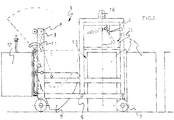
Figure 1 shows an exemplary embodiment of anapparatus 1 for processing feed, such as loose feed or feed in the form of bales or blocks 2. Theapparatus 1 comprises a mobilemain frame 3 with asupport frame 4 which can be moved horizontally vis-à-vis themain frame 3 by means of aroller guide 6 near the under-side of themain frame 3. Themain frame 3 is provided withswivel wheels 7. At one end themain frame 3 comprises a vertical guide 8, along which acollecting bin 9 can be moved vertically between a bottom position - shown as a continuous line inFigure 1 - and a top position - shown as a dotted line. In the top position the collecting bin can be tilted by means of a tilting guide 11. This way the collectingbin 9 can be tipped to empty it, for instance into a mixing bin or mixingrobot 12, such as shown inFigure 1 . - At the other end the
frame 3 comprises a feed pick-upzone 13, where a bale or block offeed 2 can be picked up by positioning theapparatus 1 such that thesupport frame 4 is positioned over the block or thebale 2 in question. - The
support frame 4 carries a grabbing device 14, which can be moved downwards from a resting position such as shown inFigure 1 , driven by anelectromotor 16 or similar driving mechanism arranged on top of the support frame. - The grabbing device 14 comprises two opposing rows of L-shaped
claws 17, such as shown inFigures 2 and3 . Eachclaw 17 is provided with aback plate 18 and abase plate 19 extending from the bottom edge of theback plate 18 in the direction of the opposing row ofclaws 17. At the free end the base plate comprises acutting edge 21 for cutting off a horizontal top layer of thebale 2. Theclaws 17 can be pivoted around apivot 22 between a resting position where theclaws 17 can be positioned over the top of a bale orblock 2, and a grabbing position where the cutting edges 21 of theclaws 17 penetrate into thebale 2 and cut off a top layer. InFigure 2 theclaw 17 is shown in the resting position, represented as a continuous line, while the grabbing position is represented as a dotted line. Theclaws 17 in that case are propelled individually with the aid ofhydraulic cylinders 23 under the control of a control unit (not shown). - In
Figure 3 the row ofclaws 17 is shown in the operating position in front view. If only a small quantity of feed is required, the control unit will trigger only part of theclaws 17 to cut off part of the top layer of the block or the bale. - In between the
claws 17 the grabbing device 14 comprises parallelcircular saws 24 for separating the cut-off top layer of thebale 2. After theclaws 17 have sliced off the top layer of the block or thebale 2, thecircular saws 24 saw the slice, causing it to fall apart into loose dosable feed. - An enveloping
protective cover 26 is arranged around theclaws 17 and thecircular saws 24. Theprotective cover 26 is shaped such that theclaws 17 and thecircular saws 24 can be moved in the various operating and resting positions, such as is illustrated inFigure 4 for another potential embodiment of the apparatus. - The apparatus of
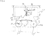
Figure 4 comprises a row ofcircular saws 24A which can be moved by means of slots between claws 17A (seeFigure 5 ). Thecircular saws 24A are capable of rotation around acommon shaft 27 and are moved with the aid of a connectingrod 28, schematically represented by means of a centre line. The connectingrod 28 comprises abottom roller guide 29, which can move along acurved bottom guide 31 in the envelopingprotective cover 26, and atop shaft 33, which can move along avertical guide 32 positioned symmetrically above thebottom guide 31 in anarm 36 of the support frame 4A. The two outermost points of theguide 31 are in an essentially horizontal straight line. Between the outermost points theguide 31 is bent upwards. At the top end the connectingrod 28 is driven by ahydraulic cylinder 34. Thecylinder 34 moves the top end of the connectingrod 28 back and forth, which movement is converted by means of theguides circular saw 24. Thehorizontal guide 31 is bent such that thecircular saws 24A are moved back and forth in a straight line Z between a first outermost position - illustrated in the drawing as the continuous line Y - and a second outermost position - illustrated in the drawing as the dotted line Y'. -
Figure 5 shows a different cross-section of the apparatus ofFigure 4 . This cross-section shows the claws 17A, which in this embodiment comprise a curvedbottom end 30. The claws are hinged to suspension points 25 of the support frame 4A and can be moved in one another's direction by means of cylinders 23A. - In another potential embodiment also the
claws 17, 17A can be moved up and down by means of a vertical guide. As a result of this the last remnants of feed on the floor can be removed more easily, so that as little residual feed as possible is left on the floor. -
Figure 6 is a schematic representation of the positioning of the parallelcircular saws 24 between theclaws 17. The cutting edges 21 of thebase plates 19 are configured as triangular points 37 to allow a better penetration into the compacted feed. Thecircular saws 24 are positioned in a slot 38 between theclaws 17 in a position which is always midway between two points 37, because there the feed will concentrate when theclaws 17 are pushed along through the compacted feed. The tips of the teeth can be rounded to ensure that less feed sticks to the knives. - After the
claws 17 have cut off the top layer of a bale orblock 2, thecircular saws 24 separate the top layer into dosable feed. Theclaws 17 remain in the grabbing position and in doing so keep the separate feed together. The grabbing device 14 is put in the top position with the aid of amotor drive 16 andsteel cable 20 guided along of apulley guide 15. Next, thesupport frame 4 driven by a hydraulic cylinder (not shown) is moved to thecollecting bin 9, which is in the top position. When thesupport frame 4 with the grabbing device 14 has been positioned above the collectingbin 9, theclaws 17 are moved apart and the separated feed falls into thecollecting bin 9. Next, thesupport frame 4 with the grabbing device 14 is returned to the original position, where thesupport frame 4 can be placed over abale 2 once again. - In addition, the
apparatus 1 is provided with weighing means, made up of weighing bars at the swivel wheels 7 (not shown). This enables the quantity of separated feed in thecollecting bin 9 and between theclaws 17 of the grabbing device 14 to be weighed precisely. The control unit can be programmed to make a continuous comparison between the weighed quantity of separated feed in theapparatus 1 and a value for the required quantity of feed entered beforehand. As soon as the desired quantity has been collected, the control unit can put the grabbing device 14 in the resting position. - To empty the
collecting bin 9, theapparatus 1 can travel to themixer 12 and/or themixer 12 can be moved to theapparatus 1. The collectingbin 9 can then be tilted from the highest position to the outfeed position, where the feed from the collectingbin 9 is put in themixer 12. If so desired, the feed in themixer 12 may be mixed with further feed components. -
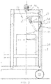
Figure 7 shows an alternative embodiment where thecollecting bin 9 is connected with a hingedflange 35 to a verticalhydraulic cylinder 39, which can move thecollecting bin 9 between a collecting position A (shown as a continuous line) and a high position B (shown as a dotted line). In the high position B thecollecting bin 9 can be moved over a bale or block, so that the apparatus as a whole can be positioned over a row of bales. From the low collecting position A thecollecting bin 9 can be tilted with the aid of a schematically representedsecond cylinder 40 into an unloading position C, also shown as a dotted line. This is the position in which the collecting bin is tipped to empty it, for instance into a mixer or mixingrobot 12. - On the under-side the
collecting bin 9 is provided with a boss orridge 41. A tiltinglock 42 hooks behind theridge 41 in order to prevent thecollecting bin 9 from tipping inadvertently. Using a schematically representedthird cylinder 43, thelock 42 can be tilted to one side, whereupon thecollecting bin 9 can be tipped. -
Figure 8 is a schematic representation in top view of afeed kitchen 45 in which anapparatus 1 is arranged. In thefeed kitchen 45 there are rows of bales or blocks 2 of different types, both round bales and rectangular bales or blocks. Theapparatus 1 is connected to apower cable 46 which can be rolled automatically and is pivotably connected to a suspension means. Amixer 12 can be moved on arail guide 47 or can travel across the floor. Theapparatus 1 is positioned over afront bale 2 of the central row of rectangular bales or blocks. - Different types of feed are cut off different bales or blocks and are weighed and collected in the
collecting bin 9 of theapparatus 1 until thecollecting bin 9 contains a complete feed mixture of the desired composition. Next, theapparatus 1 travels to a station where the composition is dumped into themixer 12. If themixer 12 has not yet returned from a previous feeding alley, theapparatus 1 will await the return of themixer 12. -
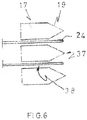
Figures 9 and 10 show an alternative apparatus for processing feed for livestock. The embodiment is the same as the embodiment ofFigure 5 , except that the claws 17B are provided on either side withside walls 48 each provided with acutting edge 49. The cutting edges 49 connect the outermost points of the J-shaped claws 17B. This enables the claws 17B to cut through the feed themselves and no separate circular saws or other separating means are required. The cutting edges 49 are curved, so that they overlap with each other to some extent in the closed position of the claws 17B. The cutting edges can for instance be serrated or curved to prevent the crop from sliding down the cutting edges 49. -
Figure 11 is a schematic representation of theapparatus 1 ofFigure 1 with a bin or container 51 disposed in the feed pick-uproom 13 beneath theclaws 17 of thesupport frame 4. The bin 51 is filled withloose crop 52. Theclaws 17 can be moved downwards to grab the loose crop and lift it. Thesupport frame 4 can then be moved in theframe 3 to the collecting bin. Next, theclaws 17 can put the collected loose crop in thecollecting bin 9. -
Figure 12 shows a further variation wherein the claws 17C are provided with side walls 48C which are provided with aknife 55 on their free edge. By means of acrankshaft transmission 56 or driven by, for instance, a hydraulic cylinder, theknife 55 is moved up and down along the edge of the side wall 48C of the claw 17C by means of aguide 54 as the claw 17C pivots. This makes cutting the feed off easier. The cutting edge of thebase plate 19C is also provided with such a reciprocating knife. - The apparatus further comprises ejector plates 57, which are mounted essentially at right angles to the back plate 18C of the claw. The ejector plates 57 are connected to the support frame 4C. The back plate 18C of the claw comprises slots (not shown) through which the ejector plates protrude. When the claw 17C is moved back and forth, the ejector plates 57 slide into the interior of the
claw 17 via the slots. When unloading the feed into the collecting bin, the feed is thus ejected by the ejector plates.
Claims (10)
- Grabber (104) for separating feed for live stock, such as bales, blocks or loose fodder, the grabber being provided with two claws (17, 109) which can be moved between an open position and a closed position, wherein the claws are both provided with a base plate (19C) with a cutting edge comprising a reciprocating knife.
- Grabber according to claim 1, wherein the claws are J-shaped or L-shaped in side view, wherein the L- or J-shaped claws (17, 109) are provided with side walls having a cutting edge, wherein cutting edges connect up when the grabber is closed.
- Grabber according to claim 2, wherein the claws (17) comprise knives (55) which extend over the full length of the cutting edges of the side walls and which are moveable up and down by means of a guide in a direction parallel to the cutting edge when the claws (17) are moved between the resting position and the grabbing position.
- Grabber according to any preceding claim, wherein the movement of the claws (17) is guided in order to have the cutting edge of the base plates of the claws travel along a straight line during movement of the claws.
- Grabber according to claim 4, wherein the grabber (104) comprises a frame (123) with a slotted guide (124) for the two claws (109) along which the claws are moved up and down as the grabber is moved between the open position and the closed position, such that the cutting edges (112) of the base plates follow an essentially horizontal path.
- Grabber according to any preceding claim, wherein the claws (17) are provided with slots for receiving ejector plates (57), which are mounted to a support frame (4C) and extend in a direction parallel to the direction of movement of the claws (17) between the resting position and the grabbing position.
- Grabber according to any preceding claim, wherein the claws enclose a grabbing zone (117), wherein at least one of the claws is provided with one or more separating means (116) inside a grabbing zone enclosed by the claws, said separating means being made up of one or more knives, for instance a row of parallel circular knives or circular saws (116) on a common drive shaft (118).
- Grabber according to claim 7, wherein the two claws (109) are provided with a row of parallel circular knives or circular saws (116), wherein in the closed position of the grabber the circular saws of one row partially overlap with the circular saws of the other row in side view of the grabber.
- Grabber according to any one of the preceding claims, wherein the two claws (109) can each be tilted around their own pivot (113), wherein the two pivots are parallel and wherein the two claws are provided with a toothed segment (121) extending from the pivot in the direction of the toothed segment of the other claw, wherein the two toothed segments are provided in mirror image with teeth (122) of such curvature and length that the two sets of teeth mesh together as the claws are moved between the open position and the closed position.
- Grabber according to claim 3, wherein the knives (55) comprise cutting teeth.
Applications Claiming Priority (3)
| Application Number | Priority Date | Filing Date | Title |
|---|---|---|---|
| NL2010541A NL2010541C2 (en) | 2013-03-28 | 2013-03-28 | DEVICE FOR PROCESSING FEED. |
| NL2011357A NL2011357C2 (en) | 2013-03-28 | 2013-08-29 | DEVICE FOR PROCESSING FEED. |
| EP14162382.7A EP2783567B8 (en) | 2013-03-28 | 2014-03-28 | Device for processing fodder |
Related Parent Applications (2)
| Application Number | Title | Priority Date | Filing Date |
|---|---|---|---|
| EP14162382.7A Division EP2783567B8 (en) | 2013-03-28 | 2014-03-28 | Device for processing fodder |
| EP14162382.7A Division-Into EP2783567B8 (en) | 2013-03-28 | 2014-03-28 | Device for processing fodder |
Publications (3)
| Publication Number | Publication Date |
|---|---|
| EP2820942A2 EP2820942A2 (en) | 2015-01-07 |
| EP2820942A3 EP2820942A3 (en) | 2015-03-11 |
| EP2820942B1 true EP2820942B1 (en) | 2017-02-15 |
Family
ID=50389323
Family Applications (2)
| Application Number | Title | Priority Date | Filing Date |
|---|---|---|---|
| EP14187355.4A Revoked EP2820942B1 (en) | 2013-03-28 | 2014-03-28 | Grabber for separating feed for livestock |
| EP14162382.7A Not-in-force EP2783567B8 (en) | 2013-03-28 | 2014-03-28 | Device for processing fodder |
Family Applications After (1)
| Application Number | Title | Priority Date | Filing Date |
|---|---|---|---|
| EP14162382.7A Not-in-force EP2783567B8 (en) | 2013-03-28 | 2014-03-28 | Device for processing fodder |
Country Status (2)
| Country | Link |
|---|---|
| EP (2) | EP2820942B1 (en) |
| NL (1) | NL2011357C2 (en) |
Families Citing this family (2)
| Publication number | Priority date | Publication date | Assignee | Title |
|---|---|---|---|---|
| CN104760073B (en) * | 2015-04-10 | 2017-01-25 | 有友食品股份有限公司 | Transmission mechanism for chicken feet cutting machine |
| NL2020010B1 (en) * | 2017-12-04 | 2019-06-11 | Triodor Arge | Bucket grabber for grabbing feed, attachable and detachable cutting device for a bucket grabber, automatic feeding system for farm animals provided with the bucket grabber and method of cutting a bale of feed using a bucket grabber's closing force |
Citations (14)
| Publication number | Priority date | Publication date | Assignee | Title |
|---|---|---|---|---|
| US2571502A (en) | 1949-06-24 | 1951-10-16 | Lyle R Uhland | Foliage removal bucket |
| GB729501A (en) | 1952-11-27 | 1955-05-04 | Priestman Brothers | Improvements relating to grabs |
| US3038620A (en) | 1960-09-09 | 1962-06-12 | Raymond H Collin | Rotatable pick-up and deposit device |
| BE863397A (en) | 1978-01-27 | 1978-05-16 | Thomas Joris J | GRIPPER FOR LIFTING GEAR AND CUTTING MECHANISM USED WITH IT |
| EP0506158A2 (en) | 1991-03-01 | 1992-09-30 | Trioliet Mullos B.V. | Device for taking out and distributing ensilage material |
| US5193873A (en) | 1989-12-15 | 1993-03-16 | Centro De Investigacion Y. Asistencia Tecnica Del Estado De Queretaro, A.C. | Sugar cane grab |
| DE4327864A1 (en) | 1993-08-19 | 1995-02-23 | Von Der Thomas Saal | Mixing gripper for composting installations |
| EP0677477A1 (en) | 1994-03-22 | 1995-10-18 | Baggermaatschappij Boskalis Bv | Grab |
| DE29615434U1 (en) | 1996-09-05 | 1996-11-28 | Strautmann & Soehne | Gripping bucket for removing silage from flat silos |
| NL1000659C1 (en) | 1995-06-26 | 1996-12-31 | Oord Acz B V Van | Scoop type material lifting unit |
| US5729920A (en) | 1993-04-15 | 1998-03-24 | Taylor; William | Attachment for a grab implement |
| US20020129590A1 (en) | 2001-03-14 | 2002-09-19 | Trioliet Mullos B.V. | Silage cutting implement |
| EP1452087A2 (en) | 2003-02-14 | 2004-09-01 | Trioliet Mullos B.V. | Method and apparatus for removing a quantity of fodder from a stock thereof |
| FR2874477A1 (en) | 2004-08-31 | 2006-03-03 | Mb Nutrimel Entpr Unipersonnel | Product e.g. fodder, mixing and dispensing machine for e.g. livestock feeding, has chassis extending outside by platform, and loading device including cup lifting apparatus to remove product doses and to pour them inside case |
Family Cites Families (13)
| Publication number | Priority date | Publication date | Assignee | Title |
|---|---|---|---|---|
| US938338A (en) * | 1909-02-08 | 1909-10-26 | Joshua B Rickards | Dredging-bucket. |
| US2176921A (en) * | 1938-03-14 | 1939-10-24 | Samuel G Neff | Grapple jet device |
| DE2415664A1 (en) * | 1974-04-01 | 1975-10-16 | Krupp Gmbh | METHOD OF OPERATING A GRIPPER FOR BULK GOODS AND GRIPPERS |
| DE2611648A1 (en) * | 1976-03-19 | 1977-09-22 | Max Hagmeyer | Silage extractor for tall silos - has cable and pulley operated grab with two side tines with facing cutter blades |
| DE3101350A1 (en) | 1981-01-17 | 1982-11-04 | B. Strautmann & Söhne GmbH u. Co, 4518 Bad Laer | Device for cutting off silage blocks |
| DE3510401A1 (en) * | 1985-03-22 | 1986-09-25 | Klaus-Peter 4518 Bad Laer Strautmann | Silo-bale distributor |
| DE3815229A1 (en) * | 1988-05-05 | 1989-11-16 | Strautmann & Soehne | Feed mixing vehicle |
| US6126216A (en) * | 1999-12-01 | 2000-10-03 | Tollefson; James S. | Bucket attachment for log grapple |
| US6347464B1 (en) * | 1999-12-29 | 2002-02-19 | Gene Klager | Self-cleaning hydraulic clam bucket |
| EP1516530A1 (en) * | 2003-09-22 | 2005-03-23 | Mullos B.V. Trioliet | Movable apparatus for mixing fodder |
| NL1033349C2 (en) * | 2007-02-06 | 2008-08-07 | Maasland Nv | Feed wagon for feeding animals such as cows. |
| NL1033589C2 (en) * | 2007-03-26 | 2008-09-29 | Maasland Nv | Assembly of a milking robot with a milking robot feeding place, and device for gripping and moving material. |
| NL1036244C2 (en) * | 2008-11-26 | 2010-05-27 | Lely Patent Nv | FEED TRANSACTION DEVICE AND A COMPOSITION THEREOF. |
-
2013
- 2013-08-29 NL NL2011357A patent/NL2011357C2/en not_active IP Right Cessation
-
2014
- 2014-03-28 EP EP14187355.4A patent/EP2820942B1/en not_active Revoked
- 2014-03-28 EP EP14162382.7A patent/EP2783567B8/en not_active Not-in-force
Patent Citations (14)
| Publication number | Priority date | Publication date | Assignee | Title |
|---|---|---|---|---|
| US2571502A (en) | 1949-06-24 | 1951-10-16 | Lyle R Uhland | Foliage removal bucket |
| GB729501A (en) | 1952-11-27 | 1955-05-04 | Priestman Brothers | Improvements relating to grabs |
| US3038620A (en) | 1960-09-09 | 1962-06-12 | Raymond H Collin | Rotatable pick-up and deposit device |
| BE863397A (en) | 1978-01-27 | 1978-05-16 | Thomas Joris J | GRIPPER FOR LIFTING GEAR AND CUTTING MECHANISM USED WITH IT |
| US5193873A (en) | 1989-12-15 | 1993-03-16 | Centro De Investigacion Y. Asistencia Tecnica Del Estado De Queretaro, A.C. | Sugar cane grab |
| EP0506158A2 (en) | 1991-03-01 | 1992-09-30 | Trioliet Mullos B.V. | Device for taking out and distributing ensilage material |
| US5729920A (en) | 1993-04-15 | 1998-03-24 | Taylor; William | Attachment for a grab implement |
| DE4327864A1 (en) | 1993-08-19 | 1995-02-23 | Von Der Thomas Saal | Mixing gripper for composting installations |
| EP0677477A1 (en) | 1994-03-22 | 1995-10-18 | Baggermaatschappij Boskalis Bv | Grab |
| NL1000659C1 (en) | 1995-06-26 | 1996-12-31 | Oord Acz B V Van | Scoop type material lifting unit |
| DE29615434U1 (en) | 1996-09-05 | 1996-11-28 | Strautmann & Soehne | Gripping bucket for removing silage from flat silos |
| US20020129590A1 (en) | 2001-03-14 | 2002-09-19 | Trioliet Mullos B.V. | Silage cutting implement |
| EP1452087A2 (en) | 2003-02-14 | 2004-09-01 | Trioliet Mullos B.V. | Method and apparatus for removing a quantity of fodder from a stock thereof |
| FR2874477A1 (en) | 2004-08-31 | 2006-03-03 | Mb Nutrimel Entpr Unipersonnel | Product e.g. fodder, mixing and dispensing machine for e.g. livestock feeding, has chassis extending outside by platform, and loading device including cup lifting apparatus to remove product doses and to pour them inside case |
Non-Patent Citations (1)
| Title |
|---|
| "Lely voert automatisch - voerhoogtesensor maakt verschil", VEEHOUDERIJ TECHNIEK, May 2012 (2012-05-01), pages 31 - 33, XP055391270 |
Also Published As
| Publication number | Publication date |
|---|---|
| EP2783567B1 (en) | 2017-03-08 |
| EP2783567B8 (en) | 2017-08-02 |
| EP2783567A2 (en) | 2014-10-01 |
| EP2820942A2 (en) | 2015-01-07 |
| EP2783567A3 (en) | 2014-12-17 |
| EP2820942A3 (en) | 2015-03-11 |
| NL2011357C2 (en) | 2014-09-30 |
Similar Documents
| Publication | Publication Date | Title |
|---|---|---|
| US4597703A (en) | Bale handling and hay distributing apparatus | |
| EP3103321B1 (en) | Bale processor and binding remover | |
| CN108337994B (en) | Intelligent combine and method for classifying and harvesting hemp agricultural products | |
| US20090019826A1 (en) | Method and apparatus for processing plant materials for bio-fuel production | |
| US10674675B2 (en) | Processing of blocks or bales of feed | |
| EP2820942B1 (en) | Grabber for separating feed for livestock | |
| CA2592554A1 (en) | Agricultural bale cutter | |
| EP2386201B1 (en) | Apparatus for separating and mixing feed for livestock | |
| CS207359B2 (en) | Facility for separating the sappy fodder,for lifting the separated block of fooder and for transport thereof for the desired place | |
| DE3112743A1 (en) | Apparatus for the supplying and discharging of animal feed | |
| JP4362184B2 (en) | Whole crop roll baler | |
| EP1449426A2 (en) | Equipment for cutting, loading and mixing fibrous products and its operating process | |
| NL2010541C2 (en) | DEVICE FOR PROCESSING FEED. | |
| NL1004809C2 (en) | Comminution device with tilting loading mechanism. | |
| EP0046718B1 (en) | Trailer for loading, mixing and delivering silage | |
| DE3235781C2 (en) | ||
| CN110775384A (en) | Automatic bag cutting device | |
| DE1431839C3 (en) | ||
| CN212829568U (en) | Automatic bag cutting device | |
| DK2826359T3 (en) | Self-filling feed mixer wagon comprising a filling device | |
| RU2399199C1 (en) | Cattle-feeder | |
| RU28423U1 (en) | Feed chopper | |
| JP2003169535A (en) | Roll baler | |
| RU75534U1 (en) | DEVICE FOR CUTTING ROLLS OF SENAGE | |
| WO2020153858A1 (en) | Device for extracting feed |
Legal Events
| Date | Code | Title | Description |
|---|---|---|---|
| PUAI | Public reference made under article 153(3) epc to a published international application that has entered the european phase |
Free format text: ORIGINAL CODE: 0009012 |
|
| 17P | Request for examination filed |
Effective date: 20141001 |
|
| AC | Divisional application: reference to earlier application |
Ref document number: 2783567 Country of ref document: EP Kind code of ref document: P |
|
| AK | Designated contracting states |
Kind code of ref document: A2 Designated state(s): AL AT BE BG CH CY CZ DE DK EE ES FI FR GB GR HR HU IE IS IT LI LT LU LV MC MK MT NL NO PL PT RO RS SE SI SK SM TR |
|
| AX | Request for extension of the european patent |
Extension state: BA ME |
|
| PUAL | Search report despatched |
Free format text: ORIGINAL CODE: 0009013 |
|
| AK | Designated contracting states |
Kind code of ref document: A3 Designated state(s): AL AT BE BG CH CY CZ DE DK EE ES FI FR GB GR HR HU IE IS IT LI LT LU LV MC MK MT NL NO PL PT RO RS SE SI SK SM TR |
|
| AX | Request for extension of the european patent |
Extension state: BA ME |
|
| RIC1 | Information provided on ipc code assigned before grant |
Ipc: B66C 3/04 20060101ALI20150204BHEP Ipc: A01F 25/20 20060101ALI20150204BHEP Ipc: A01F 29/00 20060101ALI20150204BHEP Ipc: A01K 5/02 20060101ALI20150204BHEP Ipc: A01K 5/00 20060101AFI20150204BHEP |
|
| R17P | Request for examination filed (corrected) |
Effective date: 20150904 |
|
| RBV | Designated contracting states (corrected) |
Designated state(s): AL AT BE BG CH CY CZ DE DK EE ES FI FR GB GR HR HU IE IS IT LI LT LU LV MC MK MT NL NO PL PT RO RS SE SI SK SM TR |
|
| 17Q | First examination report despatched |
Effective date: 20160203 |
|
| GRAP | Despatch of communication of intention to grant a patent |
Free format text: ORIGINAL CODE: EPIDOSNIGR1 |
|
| INTG | Intention to grant announced |
Effective date: 20160831 |
|
| GRAS | Grant fee paid |
Free format text: ORIGINAL CODE: EPIDOSNIGR3 |
|
| STAA | Information on the status of an ep patent application or granted ep patent |
Free format text: STATUS: GRANT OF PATENT IS INTENDED |
|
| GRAA | (expected) grant |
Free format text: ORIGINAL CODE: 0009210 |
|
| STAA | Information on the status of an ep patent application or granted ep patent |
Free format text: STATUS: THE PATENT HAS BEEN GRANTED |
|
| AC | Divisional application: reference to earlier application |
Ref document number: 2783567 Country of ref document: EP Kind code of ref document: P |
|
| AK | Designated contracting states |
Kind code of ref document: B1 Designated state(s): AL AT BE BG CH CY CZ DE DK EE ES FI FR GB GR HR HU IE IS IT LI LT LU LV MC MK MT NL NO PL PT RO RS SE SI SK SM TR |
|
| REG | Reference to a national code |
Ref country code: CH Ref legal event code: EP Ref country code: GB Ref legal event code: FG4D |
|
| REG | Reference to a national code |
Ref country code: IE Ref legal event code: FG4D |
|
| REG | Reference to a national code |
Ref country code: AT Ref legal event code: REF Ref document number: 867368 Country of ref document: AT Kind code of ref document: T Effective date: 20170315 |
|
| REG | Reference to a national code |
Ref country code: FR Ref legal event code: PLFP Year of fee payment: 4 |
|
| REG | Reference to a national code |
Ref country code: DE Ref legal event code: R096 Ref document number: 602014006770 Country of ref document: DE |
|
| REG | Reference to a national code |
Ref country code: NL Ref legal event code: FP |
|
| REG | Reference to a national code |
Ref country code: SE Ref legal event code: TRGR |
|
| REG | Reference to a national code |
Ref country code: LT Ref legal event code: MG4D |
|
| PG25 | Lapsed in a contracting state [announced via postgrant information from national office to epo] |
Ref country code: GR Free format text: LAPSE BECAUSE OF FAILURE TO SUBMIT A TRANSLATION OF THE DESCRIPTION OR TO PAY THE FEE WITHIN THE PRESCRIBED TIME-LIMIT Effective date: 20170516 Ref country code: FI Free format text: LAPSE BECAUSE OF FAILURE TO SUBMIT A TRANSLATION OF THE DESCRIPTION OR TO PAY THE FEE WITHIN THE PRESCRIBED TIME-LIMIT Effective date: 20170215 Ref country code: HR Free format text: LAPSE BECAUSE OF FAILURE TO SUBMIT A TRANSLATION OF THE DESCRIPTION OR TO PAY THE FEE WITHIN THE PRESCRIBED TIME-LIMIT Effective date: 20170215 Ref country code: LT Free format text: LAPSE BECAUSE OF FAILURE TO SUBMIT A TRANSLATION OF THE DESCRIPTION OR TO PAY THE FEE WITHIN THE PRESCRIBED TIME-LIMIT Effective date: 20170215 Ref country code: NO Free format text: LAPSE BECAUSE OF FAILURE TO SUBMIT A TRANSLATION OF THE DESCRIPTION OR TO PAY THE FEE WITHIN THE PRESCRIBED TIME-LIMIT Effective date: 20170515 |
|
| PG25 | Lapsed in a contracting state [announced via postgrant information from national office to epo] |
Ref country code: BG Free format text: LAPSE BECAUSE OF FAILURE TO SUBMIT A TRANSLATION OF THE DESCRIPTION OR TO PAY THE FEE WITHIN THE PRESCRIBED TIME-LIMIT Effective date: 20170515 Ref country code: PT Free format text: LAPSE BECAUSE OF FAILURE TO SUBMIT A TRANSLATION OF THE DESCRIPTION OR TO PAY THE FEE WITHIN THE PRESCRIBED TIME-LIMIT Effective date: 20170615 Ref country code: ES Free format text: LAPSE BECAUSE OF FAILURE TO SUBMIT A TRANSLATION OF THE DESCRIPTION OR TO PAY THE FEE WITHIN THE PRESCRIBED TIME-LIMIT Effective date: 20170215 Ref country code: RS Free format text: LAPSE BECAUSE OF FAILURE TO SUBMIT A TRANSLATION OF THE DESCRIPTION OR TO PAY THE FEE WITHIN THE PRESCRIBED TIME-LIMIT Effective date: 20170215 Ref country code: LV Free format text: LAPSE BECAUSE OF FAILURE TO SUBMIT A TRANSLATION OF THE DESCRIPTION OR TO PAY THE FEE WITHIN THE PRESCRIBED TIME-LIMIT Effective date: 20170215 |
|
| PG25 | Lapsed in a contracting state [announced via postgrant information from national office to epo] |
Ref country code: SK Free format text: LAPSE BECAUSE OF FAILURE TO SUBMIT A TRANSLATION OF THE DESCRIPTION OR TO PAY THE FEE WITHIN THE PRESCRIBED TIME-LIMIT Effective date: 20170215 Ref country code: IT Free format text: LAPSE BECAUSE OF FAILURE TO SUBMIT A TRANSLATION OF THE DESCRIPTION OR TO PAY THE FEE WITHIN THE PRESCRIBED TIME-LIMIT Effective date: 20170215 Ref country code: CZ Free format text: LAPSE BECAUSE OF FAILURE TO SUBMIT A TRANSLATION OF THE DESCRIPTION OR TO PAY THE FEE WITHIN THE PRESCRIBED TIME-LIMIT Effective date: 20170215 Ref country code: EE Free format text: LAPSE BECAUSE OF FAILURE TO SUBMIT A TRANSLATION OF THE DESCRIPTION OR TO PAY THE FEE WITHIN THE PRESCRIBED TIME-LIMIT Effective date: 20170215 Ref country code: RO Free format text: LAPSE BECAUSE OF FAILURE TO SUBMIT A TRANSLATION OF THE DESCRIPTION OR TO PAY THE FEE WITHIN THE PRESCRIBED TIME-LIMIT Effective date: 20170215 |
|
| REG | Reference to a national code |
Ref country code: CH Ref legal event code: PL |
|
| REG | Reference to a national code |
Ref country code: DE Ref legal event code: R026 Ref document number: 602014006770 Country of ref document: DE |
|
| REG | Reference to a national code |
Ref country code: DE Ref legal event code: R081 Ref document number: 602014006770 Country of ref document: DE Owner name: TRIOLIET HOLDING B.V., NL Free format text: FORMER OWNER: LIET, CORNELIS HENDRICUS, LOSSER, NL |
|
| PLBI | Opposition filed |
Free format text: ORIGINAL CODE: 0009260 |
|
| RAP2 | Party data changed (patent owner data changed or rights of a patent transferred) |
Owner name: TRIOLIET HOLDING B.V. |
|
| PG25 | Lapsed in a contracting state [announced via postgrant information from national office to epo] |
Ref country code: PL Free format text: LAPSE BECAUSE OF FAILURE TO SUBMIT A TRANSLATION OF THE DESCRIPTION OR TO PAY THE FEE WITHIN THE PRESCRIBED TIME-LIMIT Effective date: 20170215 Ref country code: DK Free format text: LAPSE BECAUSE OF FAILURE TO SUBMIT A TRANSLATION OF THE DESCRIPTION OR TO PAY THE FEE WITHIN THE PRESCRIBED TIME-LIMIT Effective date: 20170215 Ref country code: MC Free format text: LAPSE BECAUSE OF FAILURE TO SUBMIT A TRANSLATION OF THE DESCRIPTION OR TO PAY THE FEE WITHIN THE PRESCRIBED TIME-LIMIT Effective date: 20170215 Ref country code: SM Free format text: LAPSE BECAUSE OF FAILURE TO SUBMIT A TRANSLATION OF THE DESCRIPTION OR TO PAY THE FEE WITHIN THE PRESCRIBED TIME-LIMIT Effective date: 20170215 |
|
| REG | Reference to a national code |
Ref country code: NL Ref legal event code: PD Owner name: TRIOLIET HOLDING B.V.; NL Free format text: DETAILS ASSIGNMENT: CHANGE OF OWNER(S), ASSIGNMENT; FORMER OWNER NAME: LIET, CORNELIS HENDRICUS Effective date: 20171031 |
|
| 26 | Opposition filed |
Opponent name: OCTROOIBUREAU VAN DER LELY N.V. Effective date: 20171113 |
|
| PLAX | Notice of opposition and request to file observation + time limit sent |
Free format text: ORIGINAL CODE: EPIDOSNOBS2 |
|
| REG | Reference to a national code |
Ref country code: IE Ref legal event code: MM4A |
|
| PG25 | Lapsed in a contracting state [announced via postgrant information from national office to epo] |
Ref country code: LU Free format text: LAPSE BECAUSE OF NON-PAYMENT OF DUE FEES Effective date: 20170328 |
|
| PG25 | Lapsed in a contracting state [announced via postgrant information from national office to epo] |
Ref country code: LI Free format text: LAPSE BECAUSE OF NON-PAYMENT OF DUE FEES Effective date: 20170331 Ref country code: IE Free format text: LAPSE BECAUSE OF NON-PAYMENT OF DUE FEES Effective date: 20170328 Ref country code: SI Free format text: LAPSE BECAUSE OF FAILURE TO SUBMIT A TRANSLATION OF THE DESCRIPTION OR TO PAY THE FEE WITHIN THE PRESCRIBED TIME-LIMIT Effective date: 20170215 Ref country code: CH Free format text: LAPSE BECAUSE OF NON-PAYMENT OF DUE FEES Effective date: 20170331 |
|
| REG | Reference to a national code |
Ref country code: BE Ref legal event code: MM Effective date: 20170331 |
|
| REG | Reference to a national code |
Ref country code: FR Ref legal event code: PLFP Year of fee payment: 5 |
|
| PLBB | Reply of patent proprietor to notice(s) of opposition received |
Free format text: ORIGINAL CODE: EPIDOSNOBS3 |
|
| PGFP | Annual fee paid to national office [announced via postgrant information from national office to epo] |
Ref country code: NL Payment date: 20180328 Year of fee payment: 5 |
|
| PG25 | Lapsed in a contracting state [announced via postgrant information from national office to epo] |
Ref country code: BE Free format text: LAPSE BECAUSE OF NON-PAYMENT OF DUE FEES Effective date: 20170331 |
|
| PGFP | Annual fee paid to national office [announced via postgrant information from national office to epo] |
Ref country code: SE Payment date: 20180328 Year of fee payment: 5 Ref country code: FR Payment date: 20180326 Year of fee payment: 5 |
|
| PGFP | Annual fee paid to national office [announced via postgrant information from national office to epo] |
Ref country code: DE Payment date: 20180328 Year of fee payment: 5 |
|
| PG25 | Lapsed in a contracting state [announced via postgrant information from national office to epo] |
Ref country code: MT Free format text: LAPSE BECAUSE OF NON-PAYMENT OF DUE FEES Effective date: 20170328 |
|
| GBPC | Gb: european patent ceased through non-payment of renewal fee |
Effective date: 20180328 |
|
| REG | Reference to a national code |
Ref country code: DE Ref legal event code: R064 Ref document number: 602014006770 Country of ref document: DE Ref country code: DE Ref legal event code: R103 Ref document number: 602014006770 Country of ref document: DE |
|
| PG25 | Lapsed in a contracting state [announced via postgrant information from national office to epo] |
Ref country code: GB Free format text: LAPSE BECAUSE OF NON-PAYMENT OF DUE FEES Effective date: 20180328 |
|
| RDAF | Communication despatched that patent is revoked |
Free format text: ORIGINAL CODE: EPIDOSNREV1 |
|
| PG25 | Lapsed in a contracting state [announced via postgrant information from national office to epo] |
Ref country code: HU Free format text: LAPSE BECAUSE OF FAILURE TO SUBMIT A TRANSLATION OF THE DESCRIPTION OR TO PAY THE FEE WITHIN THE PRESCRIBED TIME-LIMIT; INVALID AB INITIO Effective date: 20140328 |
|
| RDAG | Patent revoked |
Free format text: ORIGINAL CODE: 0009271 |
|
| STAA | Information on the status of an ep patent application or granted ep patent |
Free format text: STATUS: PATENT REVOKED |
|
| 27W | Patent revoked |
Effective date: 20190211 |
|
| REG | Reference to a national code |
Ref country code: SE Ref legal event code: ECNC Ref country code: AT Ref legal event code: MA03 Ref document number: 867368 Country of ref document: AT Kind code of ref document: T Effective date: 20190211 |
|
| PG25 | Lapsed in a contracting state [announced via postgrant information from national office to epo] |
Ref country code: MK Free format text: LAPSE BECAUSE OF FAILURE TO SUBMIT A TRANSLATION OF THE DESCRIPTION OR TO PAY THE FEE WITHIN THE PRESCRIBED TIME-LIMIT Effective date: 20170215 |
|
| REG | Reference to a national code |
Ref country code: AT Ref legal event code: UEP Ref document number: 867368 Country of ref document: AT Kind code of ref document: T Effective date: 20170215 |
|
| PG25 | Lapsed in a contracting state [announced via postgrant information from national office to epo] |
Ref country code: CY Free format text: LAPSE BECAUSE OF FAILURE TO SUBMIT A TRANSLATION OF THE DESCRIPTION OR TO PAY THE FEE WITHIN THE PRESCRIBED TIME-LIMIT Effective date: 20170215 |
|
| PG25 | Lapsed in a contracting state [announced via postgrant information from national office to epo] |
Ref country code: AL Free format text: LAPSE BECAUSE OF FAILURE TO SUBMIT A TRANSLATION OF THE DESCRIPTION OR TO PAY THE FEE WITHIN THE PRESCRIBED TIME-LIMIT Effective date: 20170215 Ref country code: IS Free format text: LAPSE BECAUSE OF FAILURE TO SUBMIT A TRANSLATION OF THE DESCRIPTION OR TO PAY THE FEE WITHIN THE PRESCRIBED TIME-LIMIT Effective date: 20170615 |
|
| PG25 | Lapsed in a contracting state [announced via postgrant information from national office to epo] |
Ref country code: TR Free format text: LAPSE BECAUSE OF FAILURE TO SUBMIT A TRANSLATION OF THE DESCRIPTION OR TO PAY THE FEE WITHIN THE PRESCRIBED TIME-LIMIT Effective date: 20170215 |