EP2777096B2 - Mehrpolige steckverbindungseinheit für dreiphasen-wechselstromsysteme - Google Patents
Mehrpolige steckverbindungseinheit für dreiphasen-wechselstromsysteme Download PDFInfo
- Publication number
- EP2777096B2 EP2777096B2 EP12787422.0A EP12787422A EP2777096B2 EP 2777096 B2 EP2777096 B2 EP 2777096B2 EP 12787422 A EP12787422 A EP 12787422A EP 2777096 B2 EP2777096 B2 EP 2777096B2
- Authority
- EP
- European Patent Office
- Prior art keywords
- plug
- type connection
- insulating body
- contacts
- connection unit
- Prior art date
- Legal status (The legal status is an assumption and is not a legal conclusion. Google has not performed a legal analysis and makes no representation as to the accuracy of the status listed.)
- Active
Links
Images


Classifications
-
- H—ELECTRICITY
- H01—ELECTRIC ELEMENTS
- H01R—ELECTRICALLY-CONDUCTIVE CONNECTIONS; STRUCTURAL ASSOCIATIONS OF A PLURALITY OF MUTUALLY-INSULATED ELECTRICAL CONNECTING ELEMENTS; COUPLING DEVICES; CURRENT COLLECTORS
- H01R13/00—Details of coupling devices of the kinds covered by groups H01R12/70 or H01R24/00 - H01R33/00
- H01R13/62—Means for facilitating engagement or disengagement of coupling parts or for holding them in engagement
- H01R13/625—Casing or ring with bayonet engagement
-
- H—ELECTRICITY
- H01—ELECTRIC ELEMENTS
- H01R—ELECTRICALLY-CONDUCTIVE CONNECTIONS; STRUCTURAL ASSOCIATIONS OF A PLURALITY OF MUTUALLY-INSULATED ELECTRICAL CONNECTING ELEMENTS; COUPLING DEVICES; CURRENT COLLECTORS
- H01R13/00—Details of coupling devices of the kinds covered by groups H01R12/70 or H01R24/00 - H01R33/00
- H01R13/46—Bases; Cases
- H01R13/52—Dustproof, splashproof, drip-proof, waterproof, or flameproof cases
- H01R13/521—Sealing between contact members and housing, e.g. sealing insert
-
- H—ELECTRICITY
- H01—ELECTRIC ELEMENTS
- H01R—ELECTRICALLY-CONDUCTIVE CONNECTIONS; STRUCTURAL ASSOCIATIONS OF A PLURALITY OF MUTUALLY-INSULATED ELECTRICAL CONNECTING ELEMENTS; COUPLING DEVICES; CURRENT COLLECTORS
- H01R13/00—Details of coupling devices of the kinds covered by groups H01R12/70 or H01R24/00 - H01R33/00
- H01R13/56—Means for preventing chafing or fracture of flexible leads at outlet from coupling part
- H01R13/562—Bending-relieving
Definitions
- the invention relates to a multi-pole plug connection unit for three-phase AC systems with two plug connection parts that are complementary to one another for a kink-proof plugging into one another and with a locking sleeve which axially secures the plug connection parts in the plugged-together state, each plug connection part being constructed as a monolithic insulating body in which several electrical plug contacts are axially locked.
- Such a multi-pin connector unit is from DE 10 2006 025 134 A1 known.
- the plug connection unit has two plug connection parts which are complementary to one another for a kink-proof plugging into one another, in which mutually complementary electrical plug contacts are provided. Both plug connection parts have an insulating body in which the respective electrical plug contacts are received.
- Another multi-pin connector unit is from the EP 1 936 752 A2 known.
- the known plug-in connection unit has two plug-in connection parts, each constructed in several parts, which can be locked against one another via a locking sleeve which is likewise constructed in several parts.
- Each plug connection part is provided with electrical plug contacts which are designed as individual pins or as individual sockets. Both the individual pins and the individual sockets are integrated in insulating sleeves, which in turn merge into an insulating body made of plastic. The insulating body is pushed into a metallic hollow body, which is also part of the respective connector part.
- the object of the invention is to create a multi-pole plug connection unit of the type mentioned at the outset, which can be produced inexpensively and is miniaturized, and which can nevertheless transmit large voltages and currents.
- the combination of these features creates a miniaturized circular connector module that can transmit high electrical voltages and currents.
- the solution according to the invention is particularly advantageously suitable for transferring energy between machine tools and control devices or switch cabinets.
- the anti-rotation lock prevents the locking sleeve from being unintentionally rotated back from the locked state into the release state in which the plug connection between the plug connection parts can be separated.
- electrical cable cores of a line cable are connected to the electrical plug-in contacts, the core cross-section of which is 2.5 mm 2 .
- the core cross-section of which is 2.5 mm 2 .
- the electrical plug contacts comprise at least three contacts which are designed for maximum voltage and current ranges of 630V / 16A.
- the electrical plug-in contacts comprise at least two additional contacts, which are designed for minimum voltage and current ranges from 63 V / 10 A.
- the additional contacts form auxiliary contacts.
- the electrical plug contacts comprise at least one protective conductor contact.
- each insulating body is encapsulated by a protective sheathing, which consists of an elastic plastic material and comprises a strain relief surrounding the line cable of the respective plug-in connection part.
- the protective sheath is in one piece with the insulating body in that it is sprayed onto the already completed insulating body using an injection molding process.
- the strain relief is created by appropriate ring-like or sleeve-like sections of the protective sheath.
- each insulating body is provided in an insertion area of the cable cores with a closure element which surrounds the cable cores and which seals the rear receiving areas of the insulating body for the plug-in contacts.
- This configuration is advantageously suitable for miniaturized round plug connection modules in which an outer diameter of the plug connection parts and the locking sleeve is smaller than 23 mm.
- the embodiment is preferably also suitable for transmitting high electrical voltages and currents, so that voltage and current ranges of up to 630 V / 16 A can preferably be transmitted despite the miniaturization of the circular plug-in connection module.
- each connector part comprises a monolithic insulating body in which several electrical plug contacts are axially locked without additional miniaturization and / or the transmission of large voltage and current ranges being provided.
- the rear insertion area of each insulating body in which the receiving areas are provided for the axial insertion and locking of the electrical plug-in contacts, is sealed so that the potting compound required for the protective coating of each insulating body does not enter the receiving areas for the electrical plug-in contacts can penetrate.
- each electrical plug contact is radially movable to a limited extent within certain tolerances in its locked state in the receiving area of the insulating body.
- the axial latching forms a floating bearing for the electrical plug-in contacts, as these are located in particular in Can move radial direction within certain limits within the receiving areas of each insulating body. This floating mounting and the limited mobility enable a secure plug connection between the electrical plug contacts when the two insulating bodies are plugged together.
- each cable core in the area of the rear end face of the associated insulating body in a defined alignment and positioning by the corresponding closure element, so that the respective cable core together with the electrical plug contact attached at the front end, in particular by crimping, is essentially coaxial within the respective receiving area of the associated insulator is aligned.
- the respective closure element for each of the two insulating bodies is preferably designed in the form of a disk or plate and has plug-in profiles that match the cross-sections of the receiving areas of the respective insulating body and can be positively attached to the corresponding rear face of the insulating body.
- the closure element is glued to the end face of the insulating body or that the closure element is positively secured on the rear end face of the respective insulating body by extrusion coating of the protective sheathing for the insulating body.
- the closure element is produced as a one-piece plastic component, preferably from the same material as the associated insulating body. Alternatively, it is possible to manufacture the corresponding closure element from an elastomer or a thermoplastic elastomer.
- an outer jacket of each insulating body is provided with profiles to achieve an additional form fit for the sprayed-on protective jacket.
- a form fit is also achieved.
- the plug-in connection parts and the locking sleeve are designed as a round plug-in connection, the outer contours of the plug-in connection parts and the locking sleeve at least largely in alignment with one another in the plugged-together state. This creates an essentially cylindrical round plug connection when the plug connection parts and the locking sleeve are plugged together.
- the plug-in connection parts are designed as a plug / socket combination, as an angled plug / angled socket combination, as couplings or as bushings.
- the connector unit can be designed for various purposes.
- add-on or screw-in couplings or bushings are provided as couplings or bushings.
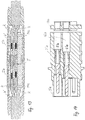
- a multi-pole connector unit for three-phase AC systems is composed of a first plug connection part 2a, 4 designed as a plug, a second plug connection part 2b, 4 designed as a socket and a locking sleeve 3 which is captively connected to the plug connection part 2b, 4 designed as a socket.
- the multi-pin connector unit is intended for signal and energy transmission between a machine tool and a control unit or a switch cabinet.
- the connector unit is miniaturized and, when plugged together, points to the Fig. 5 and 8 to 11 a diameter of approx. 21 mm.
- the diameter of the plug connection unit is preferably less than 23 mm and, in a preferred embodiment, 20.5 mm.
- Each connector part is composed of a monolithic insulating body 2a, 2b, a certain number of metallic, electrical plug-in contacts 5a, 5b and a sprayed-on protective sheath 4, each of which is provided with an molded-on strain relief for a cable harness of lines, which with its connecting strands with the metallic , electrical plug contacts 5a, 5b are connected.
- One monolithic insulating body 2b is designed as a socket.
- the other monolithic insulating body 2a is designed as a plug.
- the plug contacts 5a also referred to as contact pins, are designed as plug pins.
- the electrical plug-in contacts 5b which can also be referred to as contact pins, are designed as socket-shaped or sleeve-shaped contact pins.
- the corresponding receptacles in the respective insulating body 2a, 2b are profiled in such a way that the contact pins 5a, 5b can be pushed in axially from a rear side of the respective insulating body 2a, 2b and in their functional position inevitably lock into the receptacles. This is based on the Figures 4 and 5 good to see.
- Each monolithic insulating body 2a, 2b is made from a plastic material, preferably from polyamide.
- Three of the plug contacts 5a, 5b in each insulating body 2a, 2b are designed for an energy transmission of up to 630 volts / 16 amperes.
- Two further plug contacts in the form of contact pins of each insulating body 2a, 2b are designed as auxiliary contacts for a minimum voltage of 63 volts and a minimum current strength of 10 amperes.
- the six plug contacts 5a, 5b of each insulating body 2a, 2b each include a protective conductor contact.
- the three plug contacts, which are designed for a maximum of 630 volts / 16 amperes, are intended for the connection of copper lines with corresponding connection cables that have a line cross-section of up to 2.5 mm 2 .
- Each plug-in connection part is provided with a protective sheath 4 which is applied to the respective insulating body 2a, 2b by an injection molding process and which comprises a strain relief for the cable strands that extend from the respective electrical plug contacts 5a, 5b.
- the protective sheath is made of a suitable elastic and flexible plastic material that has good adhesive properties and good haptic properties.
- an outer casing of each insulating body is provided in a cylindrical connecting section with profiles in the form of depressions 8 into which the injection molding material of the protective casing 4 can flow positively during the manufacturing process.
- the respective protective sheathing 4 ends in the area of an unspecified annular flange of each insulating body 2a, 2b, from which point the respective connecting section of each insulating body 2a, 2b starts, viewed in the plug-in direction.
- Each connecting section of the respective insulating body 2a, 2b is composed of an axial plug-in connection section 9a, 9b and a circumferential section, not shown in detail, which is provided for axially locking the two plug-in connection parts to one another via the locking sleeve 3 as soon as the two insulating bodies 2a, 2b are plugged together.
- the one plug connection section 9a of the insulating body 2a is designed in the form of a plug.
- the other plug connection section 9b of the insulating body 2b is designed in the form of a socket.
- the socket shape of the insulating body 2b has three separately axially protruding receptacles and a triple plug in which three plug contacts (socket contacts) are received and which is designed as a monolithic composite.
- the corresponding plug connection sections represent one-piece extensions of the monolithic insulating body 2a, 2b.
- the socket-shaped plug connection section 9a of the insulating body 2a has three cylindrical receptacles into which the cylindrical receptacles of the plug connection sections 9b can be inserted.
- a receptacle adapted to the dome-like triple plug of the insulating body 2 is provided, into which the triple plug dome can be inserted axially.
- the receptacles of the plug connection sections 9b also form simple, cylindrical plug domes.
- the axial plug-in depth of the plug-in connection sections of the two insulating bodies 2a, 2b is selected to be so large that there is security against kinking and tilting in the area of the plug-in connection when the insulating bodies 2a, 2b are plugged together. How with the Fig.
- the metallic, electrical plug-in contacts which inevitably experience their mutual electrical contact when the insulating bodies 2a, 2b are plugged together, are aligned in the corresponding plug-in connection sections, which are made from the plastic material of the respective monolithic insulating body 2a, 2b.
- the corresponding plug-in profiles of the plug-in connection sections 9a, 9b are designed to fit precisely in such a way that, after they have been plugged together, a play-free fit with high contact forces is ensured.
- the locking sleeve 3 is provided, which is held captive but rotatable on the insulating body 2b.
- the locking sleeve 3 is simply snapped onto a corresponding profile on the outer circumference of the connecting section of the insulating body 2b.
- a small leaf spring 7 is provided, which serves to prevent the locking sleeve 3 from turning back when the plug-in connection parts 2a, 2b, 4 are locked together ( Fig. 11 ).
- the locking sleeve 3 is provided with cams 13 which are inserted into bayonet-like recesses 12 ( Fig. 6 ) immerse axially on the other insulating body 2a and achieve the desired axial form fit by turning.
- an additional O-ring seal 6 is provided in the area of the locking sleeve 3, which in the mated state according to the illustration according to the Fig. 5 and 9 is positioned.
- the connector unit 1 is designed to be dust- and waterproof and meets protection class IP65.
- An unlocked or locked state of the connector unit 1 can be easily recognized by an observer from the outside.
- planar surface sections of the insulating bodies 2a, 2b and the locking sleeve 3 are aligned with one another, such as Fig. 10 can be found.
- the flat surface sections are increased on all three components radially to the plug-in axis of the connector unit, as on the basis of Fig. 10 can be seen.
- the connector unit By simply rotating the locking sleeve 3, the connector unit is transferred into its axially locked state, in which the cams 13 arranged on the inside of the locking sleeve 3 dip into the circumferential pockets of the recesses 12.
- the planar surface section of the locking sleeve 3 is offset in the circumferential direction relative to the planar surface sections of the adjacent insulating bodies 2a, 2b ( Fig. 11 ).
- the plug connection unit 1 is in its locked state.
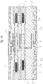
- the multi-pin connector unit according to the Figures 12 to 16 essentially corresponds to the previous one based on Figures 1 to 11 connector unit described in detail. To avoid repetition, therefore, refer to the comments on the connector unit according to the Figures 1 to 11 referenced. Functionally identical components and sections of the connector unit according to the Figures 12 to 16 have the same reference numbers but with the addition of a.
- Corresponding connection cables are also provided for the two plug connection parts 2'a, 2'b, which are provided with a plurality of cable cores K for making contact with one electrical plug contact 5'a, 5'b each.
- the connection of the cable cores K to the corresponding electrical plug contacts 5'a, 5'b takes place in the example shown by means of crimping.
- the connection cables are connected and contacted to the connector unit according to FIGS Figures 1 to 11 although this is not shown there.
- a locking lug combination 15 is provided, corresponding locking lugs being provided on the locking sleeve 3 'and on the plug connection part 2'b.
- the corresponding locking lugs are integrally formed on the locking sleeve 3 'or on the insulating body of the plug connection part 2'b.
- Both connector parts each have a monolithic insulating body 2'a, 2'b, each of which is provided with a total of six receiving areas 16a, 16b, which open to a rear end face of the respective insulating body 2'a, 2'b - viewed in the connector direction are.
- the receiving areas 16a, 16b serve for the axial introduction of the corresponding socket or plug-shaped electrical plug contacts 5'a, 5'b from the rear in order to enable the axial locking within the respective insulating body 2'a, 2'b.
- Each electrical plug contact 5'a, 5'b is each connected to a cable core K of a cable strand of the respective electrical connection cable by crimping.
- Each of the cable cores K has previously been pulled through a corresponding cutout in a closure disk 14a, 14b serving as a closure element.
- the cutouts are matched to the respective insulating sheathing of the corresponding cable core in such a way that each cutout tightly encloses the respective cable core K after it has been pulled through the closure disk 14a, 14b.
- the cutouts each have a circular cross section.
- the closure disk 14a, 14b is also provided with an integrally molded, ring-shaped cutout on both end faces in the edge region of each recess Provided thickening, which serves as a plug-in profile for insertion into the corresponding receiving area 16a, 16b.
- the dimensions of the thickened areas in the form of ring webs running around the recesses are matched to the cross-sections of the receiving areas 16a, 16b in such a way that they are axially non-positive from the respective rear end face of the respective insulating body 2'a, 2'b into the receiving areas 16a, 16b can be inserted until the flat end face of the respective closure disk 14a, 14b is flush with the end face of the corresponding insulating body 2'a, 2'b.
- the protective coating 4 ' is overmolded using a suitable plastic material, preferably a thermoplastic elastomer. Due to the tight support of the closure disks 14a, 14b on the respective rear end face of the insulating body 2'a, 2'b, no potting compound of this protective casing 4 'can penetrate into the receiving areas 16a, 16b of the insulating bodies 2'a, 2'b. Rather, a free space remains between the cable cores K and the inner walls of the receiving areas 16a, 16b, which allows a certain radial play and thus a certain mobility of the cable cores K within the receiving areas 16a, 16b.
- a suitable plastic material preferably a thermoplastic elastomer
- the electrical plug contacts 5'a, 5'b are only locked axially in a central area, the electrical plug contacts 5'a, 5'b can be inclined around the bearing in the area of the locking within certain tolerances and give way. This facilitates a later plug-in connection process with the corresponding plug-in connection part. This is because the socket-shaped and plug-shaped plug contacts 5a, 5'b to be connected to one another in pairs can align with one another to a limited extent, thereby facilitating the manually effected axial plug-in process.
- the closure disk 14a, 14b is on the one hand frictional due to the plug connections of the ring webs in the area of the recesses with the receiving areas 16a, 16b and on the other hand positively and / or cohesively through the encapsulated protective casing 4 'on the respective rear face of the insulating body 2'a, 2 'b held.
Landscapes
- Connector Housings Or Holding Contact Members (AREA)
- Details Of Connecting Devices For Male And Female Coupling (AREA)
Description
- Die Erfindung betrifft eine mehrpolige Steckverbindungseinheit für Dreiphasen-Wechselstromsysteme mit zwei für ein knicksicheres Ineinanderstecken zueinander komplementären Steckverbindungsteilen sowie mit einer die Steckverbindungsteile in zusammengestecktem Zustand gegeneinander axial sichernden Verriegelungshülse, wobei jeder Steckverbindungsteil als monolithischer Isolierkörper aufgebaut ist, in dem mehrere elektrische Steckkontakte axial verrastet sind.
- Eine derartige mehrpolige Steckverbindungseinheit ist aus der
DE 10 2006 025 134 A1 bekannt. Die Steckverbindungseinheit weist zwei für ein knicksicheres Ineinanderstecken zueinander komplementäre Steckverbindungsteile auf, in denen zueinander komplementäre elektrische Steckkontakte vorgesehen sind. Beide Steckverbindungsteile weisen einen Isolierkörper auf, in dem die jeweiligen elektrischen Steckkontakte aufgenommen sind. - Eine weitere mehrpolige Steckverbindungseinheit ist aus der
EP 1 936 752 A2 bekannt. Die bekannte Steckverbindungseinheit weist zwei jeweils mehrteilig aufgebaute Steckverbindungsteile auf, die über eine ebenfalls mehrteilig aufgebaute Verriegelungshülse gegeneinander arretierbar sind. Jeder Steckverbindungsteil ist mit elektrischen Steckkontakten versehen, die als Einzelstifte bzw. als Einzelbuchsen ausgeführt sind. Sowohl die Einzelstifte als auch die Einzelbuchsen sind in isolierenden Hülsen integriert, die wiederum in einen Isolierkörper aus Kunststoff übergehen. Der Isolierkörper ist in einen metallischen Hohlkörper eingeschoben, der ebenfalls Teil des jeweiligen Steckverbinungsteiles ist. - Aufgabe der Erfindung ist es, eine mehrpolige Steckverbindungseinheit der eingangs genannten Art zu schaffen, die kostengünstig herstellbar und miniaturisiert ausgeführt ist und dennoch große Spannungs- und Stromstärken übertragen kann.
- Diese Aufgabe wird durch die Merkmale des Anspruchs 1 gelöst. Durch die Kombination dieser Merkmale wird ein miniaturisiertes Rundsteckverbindungsmodul geschaffen, das hohe elektrische Spannungen und Stromstärken übertragen kann. Die erfindungsgemäße Lösung eignet sich in besonders vorteilhafter Weise zur Energieübertragung zwischen Werkzeugmaschinen und Steuergeräten oder Schaltschränken. Die Rückdrehsicherung verhindert ein unbeabsichtigtes Zurückdrehen der Verriegelungshülse aus dem verriegelten Zustand in den Freigabezustand, in dem die Steckverbindung zwischen den Steckverbindungsteilen getrennt werden kann.
- In Ausgestaltung der Erfindung sind an die elektrischen Steckkontakte elektrische Kabeladern eines Leitungskabels angeschlossen, deren Aderquerschnitt 2,5 mm2 beträgt. Trotz erfolgter Miniaturisierung mit einem Durchmesser der Steckverbindungseinheit von weniger als 23 mm ist der Einsatz großer Leitungsquerschnitte ermöglicht, die wiederum hohe Energieübertragungswerte ermöglichen.
- In weiterer Ausgestaltung der Erfindung umfassen die elektrischen Steckkontakte wenigstens drei Kontakte, die für maximale Spannungs- und Stromstärkebereiche von 630V/16A ausgelegt sind.
- In weiterer Ausgestaltung umfassen die elektrischen Steckkontakte wenigstens zwei Zusatzkontakte, die für minimale Spannungs- und Stromstärkebereiche ab 63 V/10 A ausgelegt sind. Die Zusatzkontakte bilden Hilfskontakte. Zudem umfassen die elektrischen Stecckontakte wenigstens einen Schutzleiterkontakt.
- In weiterer Ausgestaltung der Erfindung ist jeder Isolierkörper von einer Schutzummantelung umspritzt, die aus einem elastischen Kunststoffmaterial besteht und eine das Leitungskabel des jeweiligen Steckverbindungsteiles umgebende Zugentlastung umfasst. Die Schutzummantelung ist einstückig mit dem Isolierköper, indem sie durch ein Spritzgussverfahren auf den bereits fertiggestellten Isolierkörper aufgespritzt ist. Die Zugentlastung wird durch entsprechende ring- oder hülsenartige Abschnitte der Schutzummantelung geschaffen.
- In weiterer Ausgestaltung der Erfindung ist jeder Isolierkörper in einem Einführbereich der Kabeladern mit einem die Kabeladern umschließenden Verschlusselement versehen, das rückwärtige Aufnahmebereiche des Isolierkörpers für die Steckkontakte abdichtet. Diese Ausgestaltung ist vorteilhaft für miniaturisierte Rundsteckverbindungsmodule geeignet, bei denen ein Außendurchmesser der Steckverbindungsteile und der Verriegelungshülse kleiner ist als 23 mm. Die Ausgestaltung eignet sich vorzugsweise auch dafür, hohe elektrische Spannungen und Stromstärken zu übertragen, so dass vorzugsweise trotz Miniaturisierung des Rundsteckverbindungsmoduls Spannungs- und Stromstärkebereiche bis zu 630 V/16 A übertragen werden können. Die beschriebene Ausgestaltung kann aber auch bei einer mehrpoligen Steckverbindungseinheit vorgesehen sein, bei der jeder Steckverbindungsteil einen monolitischen Isolierkörper umfasst, in dem mehrere elektrische Stecckontakte axial verrastet sind, ohne dass eine zusätzliche Miniaturisierung und/oder die Übertragung großer Spannungs- und Stromstärkebereiche vorgesehen sind. Durch die beschriebene Ausgestaltung wird der rückwärtige Einführbereich jedes Isolierkörpers, in dem die Aufnahmebereiche für das axiale Einschieben und Verrasten der elektrischen Steckkontakte vorgesehen sind, abgedichtet, so dass Vergussmasse, die für die Schutzummantelung jedes Isolierkörpers benötigt wird, nicht in die Aufnahmebereiche für die elektrischen Steckkontakte eindringen kann. Damit bleiben die rückwärtigen Aufnahmebereiche für die elektrischen Steckkontakte in jedem Isolierkörper frei von Vergussmaterial, so dass jeder elektrische Steckkontakt in seinem im Aufnahmebereich des Isolierkörpers verrasteteten Zustand in gewissen Toleranzen begrenzt radial beweglich ist. Die axiale Verrastung bildet eine schwimmende Lagerung für die elektrischen Steckkontakte, da diese sich insbesondere in Radialrichtung in gewissen Grenzen innerhalb der Aufnahmebereiche jedes Isolierkörpers bewegen können. Diese schwimmende Lagerung und die begrenzte Beweglichkeit ermöglichen eine sichere Steckverbindung zwischen den elektrischen Steckkontakten beim Zusammenstecken der beiden Isolierkörper. Zudem wird durch diese Ausgestaltung jede Kabelader im Bereich der rückwärtigen Stirnseite des zugehörigen Isolierkörpers in einer definierten Ausrichtung und Positionierung durch das entsprechende Verschlusselement gehalten, so dass die jeweilige Kabelader gemeinsam mit dem stirnseitig insbesondere durch Vercrimpen befestigten elektrischen Steckkontakt im Wesentlichen koaxial innerhalb des jeweiligen Aufnahmebereiches des zugehörigen Isolierkörpers ausgerichtet wird. Das jeweilige Verschlusselement für jeden der beiden Isolierkörper ist vorzugsweise scheiben- oder plattenförmig gestaltet und weist auf die Querschnitte der Aufnahmebereiche des jeweiligen Isolierkörpers abgestimmte Steckprofilierungen auf, die kraftschlüssig auf die entsprechende rückwärtige Stirnseite des Isolierkörpers aufgesteckt werden zu können. Alternativ oder ergänzend ist es vorgesehen, das Verschlusselement mit der Stirnseite des Isolierkörpers zu verkleben oder eine formschlüssige Sicherung des Verschlusselementes auf der rückwärtigen Stirnseite des jeweiligen Isolierkörpers durch außenseitiges Umspritzen der Schutzummantelung für den Isolierkörper zu erzielen. Das Verschlusselement ist als einstückiges Kunststoffbauteil, vorzugsweise aus dem gleichen Material wie der zugeordnete Isolierkörper, hergestellt. Alternativ ist es möglich, das entsprechende Verschlusselement aus einem Elastomer oder einem thermoplastischen Elastomer herzustellen.
- In weiterer Ausgestaltung der Erfindung ist ein Außenmantel jedes Isolierkörpers mit Profilierungen zur Erzielung eines zusätzlichen Formschlusses für die aufgespritzte Schutzummantelung versehen. Dadurch wird zusätzlich zu einem entsprechenden Stoffschluss zwischen Schutzummantelung und Isolierkörper auch noch ein Formschluss erzielt.
- In weiterer Ausgestaltung der Erfindung sind die Steckverbindungsteile und die Verriegelungshülse als Rundsteckverbindung ausgeführt, wobei die Außenkonturen der Steckverbindungsteile und der Verriegelungshülse in zusammengestecktem Zustand zumindest weitgehend miteinander fluchten. Dadurch wird eine im Wesentlichen zylindrische Rundsteckverbindung in zusammengestecktem Zustand der Steckverbindungsteile und der Verriegelungshülse geschaffen.
- In weiterer Ausgestaltung der Erfindung sind die Steckverbindungsteile als Stecker/Buchse-Kombination, als Winkelstecker/Winkelbuchse-Kombination, als Kupplungen oder als Durchführungen ausgeführt. Dadurch kann die Steckverbindungseinheit für verschiedene Einsatzzwecke ausgebildet sein. Als Kupplungen oder Durchführungen sind insbesondere Anbau- oder Einschraubkupplungen oder - durchführungen vorgesehen.
- Weitere Vorteile und Merkmale der Erfindung ergeben sich aus den Ansprüchen. Nachfolgend ist ein bevorzugtes Ausführungsbeispiel beschrieben und anhand der Zeichnungen dargestellt.
- Fig. 1
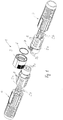
- zeigt eine Explosionsdarstellung einer Ausführungsform einer erfindungsgemäßen Steckverbindungseinheit,
- Fig. 2
- einen als Stecker ausgebildeten Steckverbindungsteil der Steckverbindungseinheit nach
Fig. 1 , jedoch ohne Schutzummantelung, - Fig. 3
- einen zu dem Steckverbindungsteil nach
Fig. 2 komplementären, als Buchse ausgebildeten Steckverbindungsteil, - Fig. 4
- eine Längsschnittdarstellung des Steckverbindungsteiles nach
Fig. 2 , - Fig. 5
- eine Längsschnittdarstellung des Steckverbindungsteiles nach
Fig. 3 , mit montierter Verriegelungshülse, - Fig. 6
- den als Stecker ausgeführten Steckverbindungsteil nach
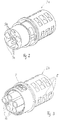
Fig. 2 , aber mit aufgespritzter Schutzummantelung, - Fig. 7
- den als Buchse ausgeführten Steckverbindungsteil nach
Fig. 3 , aber mit umspritzter Schutzummantelung und mit montierter Verriegelungshülse, - Fig. 8
- einen Längsschnitt durch die Steckverbindungseinheit nach
Fig. 1 , - Fig. 9
- in vergrößerter Darstellung einen Ausschnitt des Längsschnittes nach
Fig. 8 , - Fig. 10
- die Steckverbindungseinheit nach
Fig. 1 in gestecktem, aber unverriegeltem Zustand, - Fig. 11
- die Steckverbindungseinheit nach
Fig. 10 in gestecktem und verriegeltem Zustand, - Fig. 12
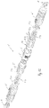
- eine Explosionsdarstellung einer weiteren Ausführungsform einer erfindungsgemäßen Steckverbindungseinheit,
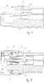
- Fig. 13
- in vergrößerter Längsschnittdarstellung die Steckverbindungseinheit nach
Fig. 12 in zusammengestecktem Funktionszustand, - Fig. 14
- einen als Stecker ausgebildeten Steckverbindungsteil der Steckverbindungseinheit nach
Fig. 13 , ohne Schutzummantelung und ohne Kabeladern, - Fig. 15
- den zu dem Steckverbindungsteil nach
Fig. 14 korrespondierenden Steckverbindungsteil der Steckverbindungseinheit nach denFig. 12 und13 mit Verriegelungshülse, aber ohne Schutzummantelung und - Fig. 16
- in vergrößerter Darstellung einen Ausschnitt der Steckverbindungseinheit nach
Fig. 13 . - Eine mehrpolige Steckverbindungseinheit für Dreiphasen-Wechselstromsysteme nach den
Fig. 1 bis 11 ist aus einem als Stecker ausgeführten ersten Steckverbindungsteil 2a, 4, aus einem als Buchse ausgeführten zweiten Steckverbindungsteil 2b, 4 sowie aus einer Verriegelungshülse 3 zusammengesetzt, die unverlierbar mit dem als Buchse ausgeführten Steckverbindungsteil 2b, 4 verbunden ist. Die mehrpolige Steckverbindungseinheit ist zur Signal- und Energieübertragung zwischen einer Werkzeugmaschine und einem Steuergerät oder einem Schaltschrank vorgesehen. Die Steckverbindungseinheit ist miniaturisiert ausgeführt und weist in zusammengestecktem Zustand nach denFig. 5 und8 bis 11 einen Durchmesser von ca. 21 mm auf. Bevorzugt beträgt der Durchmesser der Steckverbindungseinheit weniger als 23 mm und in einer bevorzugten Ausführungsform 20,5 mm. Jeder Steckverbindungsteil setzt sich aus einem monolithischen Isolierkörper 2a, 2b, einer bestimmten Anzahl metallischer, elektrischer Steckkontakte 5a, 5b und einer aufgespritzten Schutzummantelung 4 zusammen, die jeweils mit einer angespritzten Zugentlastung für einen Kabelstrang von Leitungen versehen ist, die mit ihren Anschlusslitzen mit den metallischen, elektrischen Steckkontakten 5a, 5b verbunden sind. Der eine monolithische Isolierkörper 2b ist als Buchse ausgeführt. Der andere monolithische Isolierkörper 2a ist als Stecker ausgeführt. In jedem Isolierkörper 2a, 2b sind Aufnahmen für das axiale mechanische Einrasten von insgesamt 6 elektrischen Steckkontakten 5a, 5b vorgesehen, die als Rundsteckpin ausgeführt sind. Die auch als Kontaktpin bezeichneten Steckkontakte 5a sind als Steckerstifte ausgeführt. Die ebenfalls als Kontaktpins bezeichenbaren elektrischen Steckkontakte 5b sind als buchsen- oder hülsenförmige Kontaktstifte ausgeführt. Die entsprechenden Aufnahmen im jeweiligen Isolierkörper 2a, 2b sind derart profiliert, dass die Kontaktstifte 5a, 5b axial von einer Rückseite des jeweiligen Isolierkörpers 2a, 2b her eingeschoben werden können und in ihrer Funktionsstellung zwangsläufig in den Aufnahmen formschlüssig verrasten. Dies ist anhand derFig. 4 und 5 gut erkennbar. Jeder monolithische Isolierkörper 2a, 2b ist aus einem Kunststoffmaterial, vorzugsweise aus Polyamid, hergestellt. - Drei der Steckkontakte 5a, 5b in jedem Isolierkörper 2a, 2b sind für eine Energieübertragung von bis zu 630 Volt/16 Ampere ausgelegt. Zwei weitere Stecckontakte in Form von Kontaktstiften jedes Isolierkörpers 2a, 2b sind als Hilfskontakte für eine minimale Spannung von 63 Volt und eine minimale Stromstärke von 10 Ampere ausgelegt. Zudem umfassen die sechs Steckkontakte 5a, 5b jedes Isolierkörpers 2a, 2b jeweils einen Schutzleiterkontakt. Die drei Steckkontakte, die für maximal 630 Volt/16 Ampere ausgelegt sind, sind für den Anschluss von Kupferleitungen entsprechender Anschlusskabel vorgesehen, die einen Leitungsquerschnitt bis zu 2,5 mm2 aufweisen.
- Jeder Steckverbindungsteil ist mit einer auf den jeweiligen Isolierkörper 2a, 2b durch ein Spritzgussverfahren aufgebrachten Schutzummantelung 4 versehen, die eine Zugentlastung für die Kabelstränge umfasst, die von den jeweiligen elektrischen Steckkontakten 5a, 5b abgehen. Die Schutzummantelung ist aus einem geeigneten elastischen und flexiblen Kunststoffmaterial hergestellt, das eine gute Haftwirkung und gute haptische Eigenschaften umfasst. Um die stoffschlüssige Verbindung durch das Spritzgussverfahren zwischen Isolierkörper 2a, 2b und Schutzummantelung 4 zu verbessern, ist ein Außenmantel jedes Isolierkörpers in einem zylindrischen Verbindungsabschnitt mit Profilierungen in Form von Vertiefungen 8 versehen, in die das Spritzgussmaterial der Schutzummantelung 4 beim Herstellungsvorgang formschlüssig einfließen kann. Die jeweilige Schutzummantelung 4 endet im Bereich eines nicht näher bezeichneten Ringflansches jedes Isolierkörpers 2a, 2b, ab dem in Steckrichtung gesehen der jeweilige Verbindungsabschnitt jedes Isolierkörpers 2a, 2b ansetzt. Jeder Verbindungsabschnitt des jeweiligen Isolierkörpers 2a, 2b setzt sich zusammen aus einem axialen Steckverbindungsabschnitt 9a, 9b sowie einem nicht näher bezeichneten Umfangsabschnitt, der zur axialen Verriegelung der beiden Steckverbindungsteile miteinander über die Verriegelungshülse 3 vorgesehen ist, sobald die beiden Isolierkörper 2a, 2b zusammengesteckt sind. Der eine Steckverbindungsabschnitt 9a des Isolierkörpers 2a ist in Steckerform ausgeführt. Der andere Steckverbindungsabschnitt 9b des Isolierkörpers 2b ist in Buchsenform ausgeführt. Hierzu weist die Buchsenform des Isolierkörpers 2b drei separat zueinander axial abragende Steckhülsen sowie einen Dreifachstecker auf, in dem drei Steckkontakte (Buchsenkontakte) aufgenommen sind und der als monolithischer Verbund ausgeführt ist. Die entsprechenden Steckverbindungsabschnitte stellen einstückige Fortsätze des monolithischen Isolierkörpers 2a, 2b dar. Korrespondierend hierzu weist der buchsenförmige Steckverbindungsabschnitt 9a des Isolierkörpers 2a drei zylindrische Aufnahmen auf, in die die zylindrischen Steckhülsen der Steckverbindungsabschnitte 9b einsteckbar sind. Zudem ist eine an den domartigen Dreifachstecker des Isolierkörpers 2 angepasste Aufnahme vorgesehen, in die der dreifache Steckdom axial einsteckbar ist. Auch die Steckhülsen der Steckverbindungsabschnitte 9b bilden einfache, zylindrische Steckdome. Die axiale Stecktiefe der Steckverbindungsabschnitte der beiden Isolierkörper 2a, 2b ist so groß gewählt, dass eine Knick- und Kippsicherheit im Bereich der Steckverbindung in zusammengestecktem Zustand der Isolierkörper 2a, 2b gegeben ist. Wie anhand der
Fig. 4 bis 9 erkennbar ist, sind in den entsprechenden Steckverbindungsabschnitten, die aus dem Kunststoffmaterial des jeweiligen monolithischen Isolierkörpers 2a, 2b hergestellt sind, jeweils die metallischen, elektrischen Steckkontakte ausgerichtet, die beim Zusammenstecken der Isolierkörper 2a, 2b zwangsläufig ihre gegenseitige elektrische Kontaktierung erfahren. Die entsprechenden Steckprofilierungen der Steckverbindungsabschnitte 9a, 9b sind derart passgenau gestaltet, dass nach dem Zusammenstecken ein spielfreier Sitz mit hohen Kontaktkräften gewährleistet ist. - Um zu verhindern, dass die zusammengesteckten Isolierkörper 2a, 2b sich wieder voneinander lösen, ist die Verriegelungshülse 3 vorgesehen, die auf dem Isolierkörper 2b unverlierbar, aber drehbeweglich gehalten ist. Hierzu wird die Verriegelungshülse 3 in einfacher Weise auf eine entsprechende Profilierung am Außenumfang des Verbindungsabschnittes des Isolierkörpers 2b aufgerastet. Zusätzlich ist eine kleine Blattfeder 7 vorgesehen, die als Rückdrehsicherung für die Verriegelungshülse 3 in verriegeltem Zustand der Steckverbindungsteile 2a, 2b, 4 miteinander dient (
Fig. 11 ). Zur formschlüssigen axialen Verriegelung der beiden Steckverbindungsteile 2a, 2b, 4 miteinander ist die Verriegelungshülse 3 mit Nocken 13 versehen, die in bajonettartig gestaltete Aussparungen 12 (Fig. 6 ) am anderen Isolierkörper 2a axial eintauchen und durch Verdrehen den gewünschten axialen Formschluss erzielen. - Zur Abdichtung der Steckverbindungsteile 2a, 2b, 4 miteinander in zusammengestecktem Zustand ist im Bereich der Verriegelungshülse 3 eine zusätzliche O-Ring-Dichtung 6 vorgesehen, die in zusammengestecktem Zustand gemäß der Darstellung nach den
Fig. 5 und9 positioniert ist. Die Steckverbindungseinheit 1 ist insgesamt staub- und wasserdicht ausgeführt und erfüllt die Schutzklasse IP65. - Ein unverriegelter oder verriegelter Zustand der Steckverbindungseinheit 1 ist für einen Betrachter von außen gut erkennbar. Sobald die Steckverbindungsteile 2a, 2b, 4 der Steckverbindungseinheit 1 axial zusammengesteckt, aber noch nicht verriegelt sind, fluchten plane Flächenabschnitte der Isolierkörper 2a, 2b und der Verriegelungshülse 3 miteinander, wie
Fig. 10 zu entnehmen ist. Die planen Flächenabschnitte sind an allen drei Bauteilen radial zur Steckachse der Steckverbindungseinheit erhöht, wie anhand derFig. 10 ersichtlich ist. Durch einfaches Verdrehen der Verriegelungshülse 3 wird die Steckverbindungseinheit in ihren axial verriegelten Zustand überführt, in dem die innenseitig an der Verriegelungshülse 3 angeordneten Nocken 13 in die in Umfangsrichtung verlaufenden Taschen der Aussparungen 12 eintauchen. Durch diese Verdrehung versetzt sich der plane Flächenabschnitt der Verriegelungshülse 3 in Umfangsrichtung relativ zu den planen Flächenabschnitten der benachbarten Isolierkörper 2a, 2b (Fig. 11 ). Dadurch ist für einen Betrachter erkennbar, dass sich die Steckverbindungseinheit 1 in ihrem verriegeltem Zustand befindet. - Die mehrpolige Steckverbindungseinheit nach den
Fig. 12 bis 16 entspricht im Wesentlichen der zuvor anhand derFig. 1 bis 11 ausführlich beschriebenen Steckverbindungseinheit. Zur Vermeidung von Wiederholungen wird daher auf die Ausführungen zu der Steckverbindungseinheit nach denFig. 1 bis 11 verwiesen. Funktionsgleiche Bauteile und Abschnitte der Steckverbindungseinheit nach denFig. 12 bis 16 weisen die gleichen Bezugszeichen, aber unter Hinzufügung eines auf. Bei der Ausführungsform nach denFig. 12 bis 16 sind zudem entsprechende Anschlusskabel für die beiden Steckverbindungsteile 2'a, 2'b vorgesehen, die mit mehreren Kabeladern K für die Kontaktierung mit jeweils einem elektrischen Steckkontakt 5'a, 5'b vorgesehen sind. Die Verbindung der Kabeladern K mit den entsprechenden elektrischen Steckkontakten 5'a, 5'b erfolgt beim dargestellten Beispiel über Vercrimpung. In gleicher Weise erfolgen Anschluss und Kontaktierung der Anschlusskabel an die Steckverbindungseinheit gemäß denFig. 1 bis 11 , obwohl dies dort nicht dargestellt ist. - Nachfolgend wird auf die Unterschiede der Steckverbindungseinheit nach den
Fig. 12 bis 16 relativ zur Steckverbindungseinheit nach denFig. 1 bis 11 eingegangen. - Als Rückdrehsicherung für die Verriegelungshülse 3' ist bei der Ausführungsform nach den
Fig. 12 bis 16 statt einer separaten kleinen Blattfeder eine Rastnasenkombination 15 vorgesehen, wobei entsprechende Rastnasen an der Verriegelungshülse 3' und am Steckverbindungsteil 2'b vorgesehen sind. Die entsprechenden Rastnasen sind einstückig an der Verriegelungshülse 3' bzw. am Isolierkörper des Steckverbindungsteiles 2'b angeformt. - Beide Steckverbindungsteile weisen jeweils einen monolitischen Isolierkörper 2'a, 2'b auf, die jeweils mit insgesamt sechs Aufnahmebereichen 16a, 16b versehen sind, die zu einer - in Steckverbindungsrichtung gesehen - rückwärtigen Stirnseite des jeweiligen Isolierkörpers 2'a, 2'b hin offen sind. Die Aufnahmebereiche 16a, 16b dienen zum axialen Einführen der entsprechenden buchsen- oder steckerförmigen elektrischen Stecckontakte 5'a, 5'b von der Rückseite her, um das axiale Einrasten innerhalb des jeweiligen Isolierkörpers 2'a, 2'b zu ermöglichen. Jeder elektrische Steckkontakt 5'a, 5'b wird durch Vercrimpen jeweils mit einer Kabelader K eines Kabelstranges des jeweiligen elektrischen Anschlusskabels verbunden. Jede der Kabeladern K wurde zuvor durch eine entsprechende Aussparung einer als Verschlusselement dienenden Verschlussscheibe 14a, 14b hindurchgezogen. Die Aussparungen sind derart auf die jeweilige Isolierummantelung der entsprechenden Kabelader abgestimmt, dass jede Aussparung die jeweilige Kabelader K nach dem Hindurchziehen durch die Verschlussscheibe 14a, 14b dicht umschließt. Hierzu weisen die Aussparungen jeweils einen kreisförmigen Querschnitt auf. Die Verschlussscheibe 14a, 14b ist zudem auf beiden Stirnseiten im Randbereich jeder Aussparung mit einer einstückig angeformten, ringförmigen Verdickung versehen, die als Steckprofilierung zum Einstecken in den entsprechenden Aufnahmebereich 16a, 16b dient. Die Verdickungen in Form von um die Aussparungen verlaufenden Ringstegen sind in ihren Abmessungen derart auf die Querschnitte der Aufnahmebereiche 16a, 16b abgestimmt, dass sie axial kraftschlüssig von der jeweiligen rückwärtigen Stirnseite des jeweiligen Isolierkörpers 2'a, 2'b her in die Aufnahmebereiche 16a, 16b soweit einsteckbar sind, bis die ebene Stirnfläche der jeweiligen Verschlussscheibe 14a, 14b bündig an der Stirnseite des entsprechenden Isolierkörpers 2'a, 2'b anliegt. Anhand der
Fig. 13 ist erkennbar, dass hierdurch die Kabeladern K, die mit ihren stirnseitigen Litzen mit den entsprechenden Steckkontakten 5'a, 5'b verbunden wurden, durch die als rückseitiger Stopfen für die Aufnahmebereiche 16a, 16b des Isolierkörpers 2'a, 2'b dienende Verschlussscheibe 14a, 14b im Wesentlichen koaxial ausgerichtet zu den Aufnahmebereichen 16a, 16b des Isolierkörpers 2'a, 2'b positioniert werden. - Nach dieser Vormontage erfolgt die Umspritzung mit der Schutzummantelung 4' mittels eines geeigneten Kunststoffmaterials, vorzugsweise eines thermoplastischen Elastomers. Durch die dichte Auflage der Verschlussscheiben 14a, 14b auf der jeweiligen rückwärtigen Stirnseite des Isolierkörpers 2'a, 2'b kann keine Vergussmasse dieser Schutzummantelung 4' in die Aufnahmebereiche 16a, 16b der Isolierkörper 2'a, 2'b eindringen. Vielmehr verbleibt zwischen den Kabeladern K und den Innenwandungen der Aufnahmebereiche 16a, 16b ein Freiraum, der ein gewisses radiales Spiel und damit eine gewisse Beweglichkeit der Kabeladern K innerhalb der Aufnahmebereiche 16a, 16b ermöglicht. Dadurch, dass die elektrischen Steckkontakte 5'a, 5'b lediglich in einem mittleren Bereich axial verrastet sind, können sich die elektrischen Steckkontakte 5'a, 5'b um die Lagerung im Bereich der Verrastungen in gewissen Toleranzen schräg stellen und nachgeben. Hierdurch wird ein späterer Steckverbindungsvorgang mit dem korrespondierenden Steckverbindungsteil erleichtert. Denn die paarweise miteinander zu verbindenden buchsen- und steckerförmigen Steckkontakte 5ä, 5'b können sich begrenzt zueinander ausrichten, wodurch der manuell bewirkte axiale Steckvorgang erleichtert wird. Die Verschlussscheibe 14a, 14b wird einerseits kraftschlüssig aufgrund der Steckverbindungen der Ringstege im Bereich der Aussparungen mit den Aufnahmebereichen 16a, 16b und zum anderen form- und/oder stoffschlüssig durch die umspritzte Schutzummantelung 4' an der jeweiligen rückwärtigen Stirnseite des Isolierkörpers 2'a, 2'b gehalten.
Claims (9)
- Mehrpolige Steckverbindungseinheit für Dreiphasen-Wechselstromsysteme mit zwei für ein knicksicheres Ineinanderstecken zueinander komplementären Steckverbindungsteilen (2'a, 2'b) sowie mit einer die Steckverbindungsteile (2'a, 2'b) in zusammengestecktem Zustand gegeneinander axial sichernden Verriegelungshülse (3'), wobei jeder Steckverbindungsteil (2'a, 2'b) als monolithischer Isolierkörper aufgebaut ist, in dem mehrere elektrische Steckkontakte (5'a, 5'b) axial verastet sind, dadurch gekennzeichnet, dass ein Außendurchmesser der Steckverbindungsteile (2'a, 2'b) und der Verriegelungshülse (3') kleiner ist als 23 mm, dass die Steckverbindungseinheit (1) zur Übertragung von Spannungs- und Stromstärkebereichen bis zu 630 Volt/16 Ampere gestaltet ist, und dass der Verriegelungshülse (3') eine Rückdrehsicherung zugeordnet ist, die als Rastnasenkombination (15) gestaltet ist, wobei entsprechende Rastnasen an der Verriegelungshülse (3') und am Isolierkörper einstückig angeformt sind.
- Mehrpolige Steckverbindungseinheit nach Anspruch 1, dadurch gekennzeichnet, dass an die elektrischen Steckkontakte (5'a, 5'b) elektrische Kabeladern eines Leitungskabels angeschlossen sind, deren Aderquerschnitt bis zu 2,5 mm2 beträgt.
- Mehrpolige Steckverbindungseinheit nach Anspruch 2, dadurch gekennzeichnet, dass die elektrischen Steckkontakte (5'a, 5'b) wenigstens drei Kontakte umfassen, die für maximale Spannungs- und Stromstärkebereiche bis 630 V/16 A ausgelegt sind.
- Mehrpolige Steckverbindungseinheit nach Anspruch 2 oder 3, dadurch gekennzeichnet, dass die elektrischen Steckkontakte (5'a, 5'b) wenigstens zwei Zusatzkontakte umfassen, die für minimale Spannungs- und Stromstärkebereiche ab 63 V/10 A ausgelegt sind.
- Mehrpolige Steckverbindungseinheit nach Anspruch 1, dadurch gekennzeichnet, dass jeder Isolierkörper von einer Schutzummantelung (4') umspritzt ist, die aus einem elastischen Kunststoffmaterial besteht und eine das Leitungskabel des jeweiligen Steckverbindungsteiles (2'a, 2'b) umgebende Zugentlastung umfasst.
- Mehrpolige Steckverbindungseinheit nach Anspruch 5, dadurch gekennzeichnet, dass jeder Isolierkörper (2'a, 2'b) in einem Einführbereich der Kabeladern (K) mit einem die Kabeladern (K) umschließenden Verschlusselement (14a, 14b) versehen ist, das rückwärtige Aufnahmebereiche (16a, 16b) des Isolierkörpers (2'a, 2'b) für die Steckkontakte (5ä, 5'b) abdichtet.
- Mehrpolige Steckverbindungseinheit nach Anspruch 5, dadurch gekennzeichnet, dass ein Außenmantel jedes Isolierkörpers mit Profilierungen (8) zum Erzielen eines zusätzlichen Formschlusses für die aufgespritzte Schutzummantelung (4') versehen ist.
- Mehrpolige Steckverbindungseinheit nach wenigstens einem der vorhergehenden Ansprüche, dadurch gekennzeichnet, dass die Steckverbindungsteile (2'a, 2'b) und die Verriegelungshülse (3') als Rundsteckverbindung ausgeführt sind, wobei die Außenkonturen der Steckverbindungsteile und der Verriegelungshülse in zusammengestecktem Zustand zumindest im Wesentlichen miteinander fluchten.
- Mehrpolige Steckverbindungseinheit nach wenigstens einem der vorhergehenden Ansprüche, dadurch gekennzeichnet, dass die Steckverbindungsteile als Stecker/Buchse-Kombination, als Winkelstecker/Winkelbuchse-Kombination, als Kupplungen oder als Durchführungen ausgeführt sind.
Priority Applications (1)
| Application Number | Priority Date | Filing Date | Title |
|---|---|---|---|
| PL12787422T PL2777096T5 (pl) | 2011-11-09 | 2012-11-08 | Wielobiegunowa jednostka złącza wtykowego dla trójfazowych systemów prądu przemiennego |
Applications Claiming Priority (3)
| Application Number | Priority Date | Filing Date | Title |
|---|---|---|---|
| DE102011086045 | 2011-11-09 | ||
| DE102012203459A DE102012203459A1 (de) | 2011-11-09 | 2012-03-05 | Mehrpolige Steckverbindungseinheit für Dreiphasen-Wechselstromsysteme |
| PCT/EP2012/072200 WO2013068509A1 (de) | 2011-11-09 | 2012-11-08 | Mehrpolige steckverbindungseinheit für dreiphasen-wechselstromsysteme |
Publications (3)
| Publication Number | Publication Date |
|---|---|
| EP2777096A1 EP2777096A1 (de) | 2014-09-17 |
| EP2777096B1 EP2777096B1 (de) | 2018-04-04 |
| EP2777096B2 true EP2777096B2 (de) | 2021-06-16 |
Family
ID=48145320
Family Applications (1)
| Application Number | Title | Priority Date | Filing Date |
|---|---|---|---|
| EP12787422.0A Active EP2777096B2 (de) | 2011-11-09 | 2012-11-08 | Mehrpolige steckverbindungseinheit für dreiphasen-wechselstromsysteme |
Country Status (8)
| Country | Link |
|---|---|
| US (1) | US9437970B2 (de) |
| EP (1) | EP2777096B2 (de) |
| CN (1) | CN104170179B (de) |
| DE (2) | DE102012203459A1 (de) |
| ES (1) | ES2673484T5 (de) |
| PL (1) | PL2777096T5 (de) |
| TR (1) | TR201808928T4 (de) |
| WO (1) | WO2013068509A1 (de) |
Families Citing this family (22)
| Publication number | Priority date | Publication date | Assignee | Title |
|---|---|---|---|---|
| FR3000620B1 (fr) * | 2013-01-02 | 2015-02-27 | Staubli Sa Ets | Raccord electrique avec engagement automatique |
| CN106229772B (zh) * | 2015-02-13 | 2018-04-06 | 乐清市恒通电气有限公司 | 一种海运集装箱用工业插头 |
| WO2017197134A1 (en) | 2016-05-11 | 2017-11-16 | Hubbell Incorporated | Power connector with integrated power monitoring |
| DE102016213952A1 (de) * | 2016-07-28 | 2018-02-01 | Lq Mechatronik-Systeme Gmbh | Steckverbindungsteil, geschirmte Steckverbindungseinheit und Verriegelungshülse hierfür |
| CN106252958B (zh) * | 2016-07-29 | 2019-10-08 | 中航光电科技股份有限公司 | 一种连接器 |
| CN107516784B (zh) * | 2016-07-29 | 2024-05-14 | 国网山东省电力公司桓台县供电公司 | 电力系统五触头交、直流一体充电连接装置及插座 |
| US10617985B2 (en) * | 2016-09-29 | 2020-04-14 | Rosemount Inc. | Gas sensor module with field replaceable, ingress protected, sensor filter |
| GB2559947A (en) * | 2016-11-07 | 2018-08-29 | Harwin Plc | Electrical connector |
| CN115598560A (zh) * | 2017-06-13 | 2023-01-13 | 豪倍公司(Us) | 具有综合状态监测的电源连接器 |
| DE102017118014B3 (de) * | 2017-08-08 | 2018-07-12 | Phoenix Contact Gmbh & Co. Kg | Steckverbinderteil mit einem Verriegelungselement |
| DE102018128203A1 (de) * | 2018-04-04 | 2019-10-10 | Phoenix Contact Gmbh & Co. Kg | Elektrisches Steckverbinderteil und elektrisches Steckverbindungssystem mit Verriegelung |
| CN108767576B (zh) * | 2018-04-09 | 2019-11-22 | 江苏亚龙数码科技有限公司 | 一种改进的三相电源接插件 |
| DE102018111712A1 (de) * | 2018-05-16 | 2019-11-21 | Kolektor Group D.O.O. | Elektro-Bauteil und Verfahren zu dessen Herstellung |
| US12072269B2 (en) | 2019-03-29 | 2024-08-27 | Rosemount Inc. | Self-contained calibration apparatus for gas sensor |
| DE102019113494A1 (de) * | 2019-05-21 | 2020-11-26 | Harting Electric Gmbh & Co. Kg | Kontaktträger |
| CN110048331B (zh) * | 2019-06-06 | 2021-09-17 | 圣道天德电气(山东)有限公司 | 低压配电柜 |
| CN112217042A (zh) | 2019-07-12 | 2021-01-12 | 康普技术有限责任公司 | 卡口式集束射频连接器组件 |
| AT523135B1 (de) | 2019-11-14 | 2022-09-15 | Neutrik Ag | Kontaktträger für elektrische Steckverbinder und Steckverbinder hierfür |
| US11424574B1 (en) * | 2021-03-23 | 2022-08-23 | Kunshan Outdoor Solutions Electronics Co., Ltd. | Terminal electrical connector and electrical connector assembly comprising thereof |
| CN114243406A (zh) * | 2021-11-15 | 2022-03-25 | 中航光电科技股份有限公司 | 一种新型电源线转接连接器 |
| DE102023110240B4 (de) * | 2023-04-21 | 2024-12-24 | Systec & Solutions Gmbh | Modular erweiterbare mobile Arbeitsstation |
| DE102023132087A1 (de) * | 2023-11-17 | 2025-05-22 | Weidmüller Interface GmbH & Co. KG | Leitungssatz mit Steckverbinder |
Citations (3)
| Publication number | Priority date | Publication date | Assignee | Title |
|---|---|---|---|---|
| EP0450281A1 (de) † | 1990-04-04 | 1991-10-09 | WABCO GmbH | Mehrpolige elektrische Steckvorrichtung |
| EP1936752A2 (de) † | 2006-12-19 | 2008-06-25 | Intercontec Produkt GmbH | Modulare Rundsteckverbindung |
| US20090311910A1 (en) † | 2006-05-30 | 2009-12-17 | Escha Bauelemente Gmbh | Plug type connector |
Family Cites Families (7)
| Publication number | Priority date | Publication date | Assignee | Title |
|---|---|---|---|---|
| US5100341A (en) * | 1991-03-01 | 1992-03-31 | Molex Incorporated | Electrical connector |
| DE29910960U1 (de) | 1999-06-23 | 1999-10-28 | Leuze Electronic Gmbh + Co, 73277 Owen | Steckverbinder |
| DE10034502C2 (de) | 2000-07-15 | 2002-10-31 | Lumberg Karl Gmbh & Co | Elektrischer Steckverbinder |
| US7150424B2 (en) * | 2001-03-27 | 2006-12-19 | Michael Blair Hopper | Tool support |
| DE10324794B3 (de) * | 2003-05-31 | 2004-12-09 | Woodhead Connectivity Gmbh | Elektrische Steckverbindung |
| JP4581947B2 (ja) * | 2005-09-30 | 2010-11-17 | オムロン株式会社 | コネクタ |
| EP2629377B1 (de) * | 2012-02-16 | 2020-06-17 | MD Elektronik GmbH | Kabel zur Übertragung von Signalen |
-
2012
- 2012-03-05 DE DE102012203459A patent/DE102012203459A1/de not_active Withdrawn
- 2012-11-08 PL PL12787422T patent/PL2777096T5/pl unknown
- 2012-11-08 EP EP12787422.0A patent/EP2777096B2/de active Active
- 2012-11-08 TR TR2018/08928T patent/TR201808928T4/tr unknown
- 2012-11-08 CN CN201280066511.2A patent/CN104170179B/zh active Active
- 2012-11-08 WO PCT/EP2012/072200 patent/WO2013068509A1/de not_active Ceased
- 2012-11-08 ES ES12787422T patent/ES2673484T5/es active Active
- 2012-11-08 DE DE202012013360.8U patent/DE202012013360U1/de not_active Expired - Lifetime
- 2012-11-08 US US14/357,104 patent/US9437970B2/en active Active
Patent Citations (3)
| Publication number | Priority date | Publication date | Assignee | Title |
|---|---|---|---|---|
| EP0450281A1 (de) † | 1990-04-04 | 1991-10-09 | WABCO GmbH | Mehrpolige elektrische Steckvorrichtung |
| US20090311910A1 (en) † | 2006-05-30 | 2009-12-17 | Escha Bauelemente Gmbh | Plug type connector |
| EP1936752A2 (de) † | 2006-12-19 | 2008-06-25 | Intercontec Produkt GmbH | Modulare Rundsteckverbindung |
Also Published As
| Publication number | Publication date |
|---|---|
| DE102012203459A1 (de) | 2013-05-16 |
| PL2777096T5 (pl) | 2021-10-11 |
| EP2777096B1 (de) | 2018-04-04 |
| CN104170179B (zh) | 2018-05-29 |
| TR201808928T4 (tr) | 2018-07-23 |
| US9437970B2 (en) | 2016-09-06 |
| ES2673484T5 (es) | 2021-12-09 |
| US20140295690A1 (en) | 2014-10-02 |
| PL2777096T3 (pl) | 2018-10-31 |
| EP2777096A1 (de) | 2014-09-17 |
| WO2013068509A1 (de) | 2013-05-16 |
| ES2673484T3 (es) | 2018-06-22 |
| DE202012013360U1 (de) | 2016-07-15 |
| CN104170179A (zh) | 2014-11-26 |
Similar Documents
| Publication | Publication Date | Title |
|---|---|---|
| EP2777096B2 (de) | Mehrpolige steckverbindungseinheit für dreiphasen-wechselstromsysteme | |
| EP3454427B1 (de) | Steckverbindungssatz, installationssatz und elektrische installation | |
| EP2929598B1 (de) | Verbindungsvorrichtung | |
| DE102019106980B3 (de) | Kontaktträger und Steckverbinder für eine geschirmte hybride Kontaktanordnung | |
| EP3276755A1 (de) | Steckverbindungsteil für eine geschirmte steckverbindungseinheit | |
| EP0754357B1 (de) | Verbindungssystem für elektrische leiter | |
| WO2012035030A1 (de) | Elektrischer kontakt | |
| EP1081789A2 (de) | Elektrischer Steckverbinder | |
| EP2034566A2 (de) | Photovoltaik-Steckverbindung | |
| DE102015120921B4 (de) | Steckverbinder und Steckerverbinderanordnung | |
| EP3203591A1 (de) | Steckverbinder | |
| EP1936752B1 (de) | Modulare Rundsteckverbindung | |
| WO2007113030A1 (de) | Anschlussmodul zum anschluss einer steuereinheit oder dergleichen an eine antriebseinheit | |
| EP2449302B1 (de) | Kupplungsanordnung | |
| DE102016120304B4 (de) | Abgewinkelter steckverbinder und verfahren für dessen herstellung | |
| EP1837955B1 (de) | Halteschutzbuchse für einen Steckverbinder | |
| DE102005012441B4 (de) | Elektrischer Steckverbinder sowie Verfahren zur Herstellung eines elektrischen Steckverbinders | |
| EP2190076B1 (de) | Elektrischer Steckverbinder | |
| EP3340392B1 (de) | Anordnung zum verbinden von elektrischen leitungen | |
| AT410614B (de) | Kabelstecker mit einem steckergehäuse und elektrischen kontaktelementen | |
| EP2913898A1 (de) | Elektrischer Steckverbinder und Verfahren zu dessen Montage | |
| EP3176882B1 (de) | Elektrisches kupplungsteil mit angeschlossener elektrischer leitung | |
| WO2020125991A1 (de) | Elektrische steckverbindung | |
| EP3190671B1 (de) | Potentialverteiler | |
| DE102023114105A1 (de) | Kontakteinrichtung für einen steckverbinder und steckverbinder mit zumindest einer kontakteinrichtung |
Legal Events
| Date | Code | Title | Description |
|---|---|---|---|
| REG | Reference to a national code |
Ref country code: DE Ref legal event code: R138 Ref document number: 202012013360 Country of ref document: DE Free format text: GERMAN DOCUMENT NUMBER IS 502012012503 |
|
| PUAI | Public reference made under article 153(3) epc to a published international application that has entered the european phase |
Free format text: ORIGINAL CODE: 0009012 |
|
| 17P | Request for examination filed |
Effective date: 20140604 |
|
| AK | Designated contracting states |
Kind code of ref document: A1 Designated state(s): AL AT BE BG CH CY CZ DE DK EE ES FI FR GB GR HR HU IE IS IT LI LT LU LV MC MK MT NL NO PL PT RO RS SE SI SK SM TR |
|
| DAX | Request for extension of the european patent (deleted) | ||
| 17Q | First examination report despatched |
Effective date: 20160201 |
|
| STAA | Information on the status of an ep patent application or granted ep patent |
Free format text: STATUS: EXAMINATION IS IN PROGRESS |
|
| REG | Reference to a national code |
Ref country code: DE Ref legal event code: R079 Ref document number: 502012012503 Country of ref document: DE Free format text: PREVIOUS MAIN CLASS: H01R0013625000 Ipc: H01R0013520000 |
|
| GRAP | Despatch of communication of intention to grant a patent |
Free format text: ORIGINAL CODE: EPIDOSNIGR1 |
|
| STAA | Information on the status of an ep patent application or granted ep patent |
Free format text: STATUS: GRANT OF PATENT IS INTENDED |
|
| RIC1 | Information provided on ipc code assigned before grant |
Ipc: H01R 13/625 20060101ALI20170929BHEP Ipc: H01R 13/56 20060101ALI20170929BHEP Ipc: H01R 13/52 20060101AFI20170929BHEP |
|
| INTG | Intention to grant announced |
Effective date: 20171018 |
|
| GRAS | Grant fee paid |
Free format text: ORIGINAL CODE: EPIDOSNIGR3 |
|
| GRAA | (expected) grant |
Free format text: ORIGINAL CODE: 0009210 |
|
| STAA | Information on the status of an ep patent application or granted ep patent |
Free format text: STATUS: THE PATENT HAS BEEN GRANTED |
|
| AK | Designated contracting states |
Kind code of ref document: B1 Designated state(s): AL AT BE BG CH CY CZ DE DK EE ES FI FR GB GR HR HU IE IS IT LI LT LU LV MC MK MT NL NO PL PT RO RS SE SI SK SM TR |
|
| REG | Reference to a national code |
Ref country code: GB Ref legal event code: FG4D Free format text: NOT ENGLISH |
|
| REG | Reference to a national code |
Ref country code: CH Ref legal event code: EP |
|
| REG | Reference to a national code |
Ref country code: AT Ref legal event code: REF Ref document number: 986558 Country of ref document: AT Kind code of ref document: T Effective date: 20180415 |
|
| REG | Reference to a national code |
Ref country code: IE Ref legal event code: FG4D Free format text: LANGUAGE OF EP DOCUMENT: GERMAN |
|
| REG | Reference to a national code |
Ref country code: DE Ref legal event code: R096 Ref document number: 502012012503 Country of ref document: DE |
|
| REG | Reference to a national code |
Ref country code: CH Ref legal event code: NV Representative=s name: DR. LUSUARDI AG, CH |
|
| REG | Reference to a national code |
Ref country code: ES Ref legal event code: FG2A Ref document number: 2673484 Country of ref document: ES Kind code of ref document: T3 Effective date: 20180622 |
|
| REG | Reference to a national code |
Ref country code: SE Ref legal event code: TRGR |
|
| REG | Reference to a national code |
Ref country code: NL Ref legal event code: FP |
|
| REG | Reference to a national code |
Ref country code: LT Ref legal event code: MG4D |
|
| PG25 | Lapsed in a contracting state [announced via postgrant information from national office to epo] |
Ref country code: AL Free format text: LAPSE BECAUSE OF FAILURE TO SUBMIT A TRANSLATION OF THE DESCRIPTION OR TO PAY THE FEE WITHIN THE PRESCRIBED TIME-LIMIT Effective date: 20180404 Ref country code: NO Free format text: LAPSE BECAUSE OF FAILURE TO SUBMIT A TRANSLATION OF THE DESCRIPTION OR TO PAY THE FEE WITHIN THE PRESCRIBED TIME-LIMIT Effective date: 20180704 Ref country code: BG Free format text: LAPSE BECAUSE OF FAILURE TO SUBMIT A TRANSLATION OF THE DESCRIPTION OR TO PAY THE FEE WITHIN THE PRESCRIBED TIME-LIMIT Effective date: 20180704 Ref country code: LT Free format text: LAPSE BECAUSE OF FAILURE TO SUBMIT A TRANSLATION OF THE DESCRIPTION OR TO PAY THE FEE WITHIN THE PRESCRIBED TIME-LIMIT Effective date: 20180404 |
|
| PG25 | Lapsed in a contracting state [announced via postgrant information from national office to epo] |
Ref country code: HR Free format text: LAPSE BECAUSE OF FAILURE TO SUBMIT A TRANSLATION OF THE DESCRIPTION OR TO PAY THE FEE WITHIN THE PRESCRIBED TIME-LIMIT Effective date: 20180404 Ref country code: LV Free format text: LAPSE BECAUSE OF FAILURE TO SUBMIT A TRANSLATION OF THE DESCRIPTION OR TO PAY THE FEE WITHIN THE PRESCRIBED TIME-LIMIT Effective date: 20180404 Ref country code: RS Free format text: LAPSE BECAUSE OF FAILURE TO SUBMIT A TRANSLATION OF THE DESCRIPTION OR TO PAY THE FEE WITHIN THE PRESCRIBED TIME-LIMIT Effective date: 20180404 Ref country code: GR Free format text: LAPSE BECAUSE OF FAILURE TO SUBMIT A TRANSLATION OF THE DESCRIPTION OR TO PAY THE FEE WITHIN THE PRESCRIBED TIME-LIMIT Effective date: 20180705 |
|
| REG | Reference to a national code |
Ref country code: DE Ref legal event code: R026 Ref document number: 502012012503 Country of ref document: DE |
|
| PG25 | Lapsed in a contracting state [announced via postgrant information from national office to epo] |
Ref country code: PT Free format text: LAPSE BECAUSE OF FAILURE TO SUBMIT A TRANSLATION OF THE DESCRIPTION OR TO PAY THE FEE WITHIN THE PRESCRIBED TIME-LIMIT Effective date: 20180806 |
|
| PLBI | Opposition filed |
Free format text: ORIGINAL CODE: 0009260 |
|
| PG25 | Lapsed in a contracting state [announced via postgrant information from national office to epo] |
Ref country code: RO Free format text: LAPSE BECAUSE OF FAILURE TO SUBMIT A TRANSLATION OF THE DESCRIPTION OR TO PAY THE FEE WITHIN THE PRESCRIBED TIME-LIMIT Effective date: 20180404 Ref country code: DK Free format text: LAPSE BECAUSE OF FAILURE TO SUBMIT A TRANSLATION OF THE DESCRIPTION OR TO PAY THE FEE WITHIN THE PRESCRIBED TIME-LIMIT Effective date: 20180404 Ref country code: EE Free format text: LAPSE BECAUSE OF FAILURE TO SUBMIT A TRANSLATION OF THE DESCRIPTION OR TO PAY THE FEE WITHIN THE PRESCRIBED TIME-LIMIT Effective date: 20180404 Ref country code: SK Free format text: LAPSE BECAUSE OF FAILURE TO SUBMIT A TRANSLATION OF THE DESCRIPTION OR TO PAY THE FEE WITHIN THE PRESCRIBED TIME-LIMIT Effective date: 20180404 |
|
| PLAX | Notice of opposition and request to file observation + time limit sent |
Free format text: ORIGINAL CODE: EPIDOSNOBS2 |
|
| PLAB | Opposition data, opponent's data or that of the opponent's representative modified |
Free format text: ORIGINAL CODE: 0009299OPPO |
|
| 26 | Opposition filed |
Opponent name: EUROCONNECTION S.R.L. Effective date: 20181228 |
|
| PG25 | Lapsed in a contracting state [announced via postgrant information from national office to epo] |
Ref country code: SM Free format text: LAPSE BECAUSE OF FAILURE TO SUBMIT A TRANSLATION OF THE DESCRIPTION OR TO PAY THE FEE WITHIN THE PRESCRIBED TIME-LIMIT Effective date: 20180404 |
|
| R26 | Opposition filed (corrected) |
Opponent name: EUROCONNECTION S.R.L. Effective date: 20181228 |
|
| PLBB | Reply of patent proprietor to notice(s) of opposition received |
Free format text: ORIGINAL CODE: EPIDOSNOBS3 |
|
| PG25 | Lapsed in a contracting state [announced via postgrant information from national office to epo] |
Ref country code: SI Free format text: LAPSE BECAUSE OF FAILURE TO SUBMIT A TRANSLATION OF THE DESCRIPTION OR TO PAY THE FEE WITHIN THE PRESCRIBED TIME-LIMIT Effective date: 20180404 |
|
| PG25 | Lapsed in a contracting state [announced via postgrant information from national office to epo] |
Ref country code: LU Free format text: LAPSE BECAUSE OF NON-PAYMENT OF DUE FEES Effective date: 20181108 Ref country code: MC Free format text: LAPSE BECAUSE OF FAILURE TO SUBMIT A TRANSLATION OF THE DESCRIPTION OR TO PAY THE FEE WITHIN THE PRESCRIBED TIME-LIMIT Effective date: 20180404 |
|
| REG | Reference to a national code |
Ref country code: IE Ref legal event code: MM4A |
|
| PG25 | Lapsed in a contracting state [announced via postgrant information from national office to epo] |
Ref country code: IE Free format text: LAPSE BECAUSE OF NON-PAYMENT OF DUE FEES Effective date: 20181108 |
|
| PG25 | Lapsed in a contracting state [announced via postgrant information from national office to epo] |
Ref country code: MT Free format text: LAPSE BECAUSE OF FAILURE TO SUBMIT A TRANSLATION OF THE DESCRIPTION OR TO PAY THE FEE WITHIN THE PRESCRIBED TIME-LIMIT Effective date: 20180404 |
|
| PG25 | Lapsed in a contracting state [announced via postgrant information from national office to epo] |
Ref country code: MK Free format text: LAPSE BECAUSE OF NON-PAYMENT OF DUE FEES Effective date: 20180404 Ref country code: HU Free format text: LAPSE BECAUSE OF FAILURE TO SUBMIT A TRANSLATION OF THE DESCRIPTION OR TO PAY THE FEE WITHIN THE PRESCRIBED TIME-LIMIT; INVALID AB INITIO Effective date: 20121108 Ref country code: CY Free format text: LAPSE BECAUSE OF FAILURE TO SUBMIT A TRANSLATION OF THE DESCRIPTION OR TO PAY THE FEE WITHIN THE PRESCRIBED TIME-LIMIT Effective date: 20180404 |
|
| PG25 | Lapsed in a contracting state [announced via postgrant information from national office to epo] |
Ref country code: IS Free format text: LAPSE BECAUSE OF FAILURE TO SUBMIT A TRANSLATION OF THE DESCRIPTION OR TO PAY THE FEE WITHIN THE PRESCRIBED TIME-LIMIT Effective date: 20180804 |
|
| PLAY | Examination report in opposition despatched + time limit |
Free format text: ORIGINAL CODE: EPIDOSNORE2 |
|
| PLBC | Reply to examination report in opposition received |
Free format text: ORIGINAL CODE: EPIDOSNORE3 |
|
| PUAH | Patent maintained in amended form |
Free format text: ORIGINAL CODE: 0009272 |
|
| STAA | Information on the status of an ep patent application or granted ep patent |
Free format text: STATUS: PATENT MAINTAINED AS AMENDED |
|
| 27A | Patent maintained in amended form |
Effective date: 20210616 |
|
| AK | Designated contracting states |
Kind code of ref document: B2 Designated state(s): AL AT BE BG CH CY CZ DE DK EE ES FI FR GB GR HR HU IE IS IT LI LT LU LV MC MK MT NL NO PL PT RO RS SE SI SK SM TR |
|
| REG | Reference to a national code |
Ref country code: DE Ref legal event code: R102 Ref document number: 502012012503 Country of ref document: DE |
|
| REG | Reference to a national code |
Ref country code: NL Ref legal event code: FP |
|
| REG | Reference to a national code |
Ref country code: SE Ref legal event code: RPEO |
|
| REG | Reference to a national code |
Ref country code: ES Ref legal event code: DC2A Ref document number: 2673484 Country of ref document: ES Kind code of ref document: T5 Effective date: 20211209 |
|
| REG | Reference to a national code |
Ref country code: CH Ref legal event code: U11 Free format text: ST27 STATUS EVENT CODE: U-0-0-U10-U11 (AS PROVIDED BY THE NATIONAL OFFICE) Effective date: 20251201 |
|
| PGFP | Annual fee paid to national office [announced via postgrant information from national office to epo] |
Ref country code: NL Payment date: 20251119 Year of fee payment: 14 |
|
| PGFP | Annual fee paid to national office [announced via postgrant information from national office to epo] |
Ref country code: DE Payment date: 20251126 Year of fee payment: 14 |
|
| PGFP | Annual fee paid to national office [announced via postgrant information from national office to epo] |
Ref country code: GB Payment date: 20251120 Year of fee payment: 14 |
|
| PGFP | Annual fee paid to national office [announced via postgrant information from national office to epo] |
Ref country code: AT Payment date: 20251117 Year of fee payment: 14 |
|
| PGFP | Annual fee paid to national office [announced via postgrant information from national office to epo] |
Ref country code: IT Payment date: 20251128 Year of fee payment: 14 Ref country code: FI Payment date: 20251118 Year of fee payment: 14 |
|
| PGFP | Annual fee paid to national office [announced via postgrant information from national office to epo] |
Ref country code: FR Payment date: 20251125 Year of fee payment: 14 |
|
| PGFP | Annual fee paid to national office [announced via postgrant information from national office to epo] |
Ref country code: BE Payment date: 20251118 Year of fee payment: 14 Ref country code: TR Payment date: 20251106 Year of fee payment: 14 |
|
| PGFP | Annual fee paid to national office [announced via postgrant information from national office to epo] |
Ref country code: CH Payment date: 20251201 Year of fee payment: 14 Ref country code: SE Payment date: 20251119 Year of fee payment: 14 |
|
| PGFP | Annual fee paid to national office [announced via postgrant information from national office to epo] |
Ref country code: CZ Payment date: 20251030 Year of fee payment: 14 |
|
| PGFP | Annual fee paid to national office [announced via postgrant information from national office to epo] |
Ref country code: PL Payment date: 20251024 Year of fee payment: 14 |
|
| PGFP | Annual fee paid to national office [announced via postgrant information from national office to epo] |
Ref country code: ES Payment date: 20251216 Year of fee payment: 14 |