EP2775699B1 - Farbbildverarbeitungsvorrichtung, Verfahren zur Farbbildverarbeitung und Programm zur Ausführung des Verfahrens zur Farbbildverarbeitung - Google Patents
Farbbildverarbeitungsvorrichtung, Verfahren zur Farbbildverarbeitung und Programm zur Ausführung des Verfahrens zur Farbbildverarbeitung Download PDFInfo
- Publication number
- EP2775699B1 EP2775699B1 EP14157323.8A EP14157323A EP2775699B1 EP 2775699 B1 EP2775699 B1 EP 2775699B1 EP 14157323 A EP14157323 A EP 14157323A EP 2775699 B1 EP2775699 B1 EP 2775699B1
- Authority
- EP
- European Patent Office
- Prior art keywords
- image
- processing
- colour
- correction process
- executed
- Prior art date
- Legal status (The legal status is an assumption and is not a legal conclusion. Google has not performed a legal analysis and makes no representation as to the accuracy of the status listed.)
- Active
Links
- 238000000034 method Methods 0.000 title claims description 178
- 238000012545 processing Methods 0.000 title claims description 131
- 238000012937 correction Methods 0.000 claims description 179
- 239000003086 colorant Substances 0.000 claims description 71
- 239000000463 material Substances 0.000 claims description 7
- 238000005259 measurement Methods 0.000 claims description 5
- 230000010365 information processing Effects 0.000 claims description 3
- 230000000694 effects Effects 0.000 description 10
- 238000010586 diagram Methods 0.000 description 7
- 238000006243 chemical reaction Methods 0.000 description 4
- 230000006870 function Effects 0.000 description 3
- 230000001419 dependent effect Effects 0.000 description 2
- 238000001914 filtration Methods 0.000 description 2
- 238000003384 imaging method Methods 0.000 description 2
- 230000003595 spectral effect Effects 0.000 description 2
- 238000012546 transfer Methods 0.000 description 2
- 230000015572 biosynthetic process Effects 0.000 description 1
- 230000006866 deterioration Effects 0.000 description 1
- 238000011161 development Methods 0.000 description 1
- 238000009792 diffusion process Methods 0.000 description 1
- 230000014509 gene expression Effects 0.000 description 1
- 238000009499 grossing Methods 0.000 description 1
- 238000005286 illumination Methods 0.000 description 1
- 238000012544 monitoring process Methods 0.000 description 1
- 230000003287 optical effect Effects 0.000 description 1
- 230000000007 visual effect Effects 0.000 description 1
Images


Classifications
-
- H—ELECTRICITY
- H04—ELECTRIC COMMUNICATION TECHNIQUE
- H04N—PICTORIAL COMMUNICATION, e.g. TELEVISION
- H04N1/00—Scanning, transmission or reproduction of documents or the like, e.g. facsimile transmission; Details thereof
- H04N1/46—Colour picture communication systems
- H04N1/56—Processing of colour picture signals
- H04N1/60—Colour correction or control
-
- H—ELECTRICITY
- H04—ELECTRIC COMMUNICATION TECHNIQUE
- H04N—PICTORIAL COMMUNICATION, e.g. TELEVISION
- H04N1/00—Scanning, transmission or reproduction of documents or the like, e.g. facsimile transmission; Details thereof
- H04N1/40—Picture signal circuits
- H04N1/407—Control or modification of tonal gradation or of extreme levels, e.g. background level
- H04N1/4076—Control or modification of tonal gradation or of extreme levels, e.g. background level dependent on references outside the picture
- H04N1/4078—Control or modification of tonal gradation or of extreme levels, e.g. background level dependent on references outside the picture using gradational references, e.g. grey-scale test pattern analysis
-
- H—ELECTRICITY
- H04—ELECTRIC COMMUNICATION TECHNIQUE
- H04N—PICTORIAL COMMUNICATION, e.g. TELEVISION
- H04N1/00—Scanning, transmission or reproduction of documents or the like, e.g. facsimile transmission; Details thereof
- H04N1/46—Colour picture communication systems
- H04N1/50—Picture reproducers
-
- G—PHYSICS
- G06—COMPUTING; CALCULATING OR COUNTING
- G06K—GRAPHICAL DATA READING; PRESENTATION OF DATA; RECORD CARRIERS; HANDLING RECORD CARRIERS
- G06K15/00—Arrangements for producing a permanent visual presentation of the output data, e.g. computer output printers
- G06K15/02—Arrangements for producing a permanent visual presentation of the output data, e.g. computer output printers using printers
- G06K15/18—Conditioning data for presenting it to the physical printing elements
- G06K15/1867—Post-processing of the composed and rasterized print image
- G06K15/1872—Image enhancement
- G06K15/1878—Adjusting colours
-
- H—ELECTRICITY
- H04—ELECTRIC COMMUNICATION TECHNIQUE
- H04N—PICTORIAL COMMUNICATION, e.g. TELEVISION
- H04N1/00—Scanning, transmission or reproduction of documents or the like, e.g. facsimile transmission; Details thereof
- H04N1/46—Colour picture communication systems
-
- H—ELECTRICITY
- H04—ELECTRIC COMMUNICATION TECHNIQUE
- H04N—PICTORIAL COMMUNICATION, e.g. TELEVISION
- H04N1/00—Scanning, transmission or reproduction of documents or the like, e.g. facsimile transmission; Details thereof
- H04N1/46—Colour picture communication systems
- H04N1/56—Processing of colour picture signals
- H04N1/60—Colour correction or control
- H04N1/6016—Conversion to subtractive colour signals
- H04N1/6022—Generating a fourth subtractive colour signal, e.g. under colour removal, black masking
- H04N1/6025—Generating a fourth subtractive colour signal, e.g. under colour removal, black masking using look-up tables
-
- H—ELECTRICITY
- H04—ELECTRIC COMMUNICATION TECHNIQUE
- H04N—PICTORIAL COMMUNICATION, e.g. TELEVISION
- H04N1/00—Scanning, transmission or reproduction of documents or the like, e.g. facsimile transmission; Details thereof
- H04N1/46—Colour picture communication systems
- H04N1/56—Processing of colour picture signals
- H04N1/60—Colour correction or control
- H04N1/6027—Correction or control of colour gradation or colour contrast
-
- H—ELECTRICITY
- H04—ELECTRIC COMMUNICATION TECHNIQUE
- H04N—PICTORIAL COMMUNICATION, e.g. TELEVISION
- H04N1/00—Scanning, transmission or reproduction of documents or the like, e.g. facsimile transmission; Details thereof
- H04N1/46—Colour picture communication systems
- H04N1/56—Processing of colour picture signals
- H04N1/60—Colour correction or control
- H04N1/603—Colour correction or control controlled by characteristics of the picture signal generator or the picture reproducer
- H04N1/6033—Colour correction or control controlled by characteristics of the picture signal generator or the picture reproducer using test pattern analysis
- H04N1/6038—Colour correction or control controlled by characteristics of the picture signal generator or the picture reproducer using test pattern analysis for controlling interaction among colorants
-
- H—ELECTRICITY
- H04—ELECTRIC COMMUNICATION TECHNIQUE
- H04N—PICTORIAL COMMUNICATION, e.g. TELEVISION
- H04N9/00—Details of colour television systems
- H04N9/64—Circuits for processing colour signals
-
- H—ELECTRICITY
- H04—ELECTRIC COMMUNICATION TECHNIQUE
- H04N—PICTORIAL COMMUNICATION, e.g. TELEVISION
- H04N2201/00—Indexing scheme relating to scanning, transmission or reproduction of documents or the like, and to details thereof
- H04N2201/0077—Types of the still picture apparatus
- H04N2201/0094—Multifunctional device, i.e. a device capable of all of reading, reproducing, copying, facsimile transception, file transception
Definitions
- the present invention relates to a color image processing apparatus and a method for processing a color image for correcting colors of an image output from a printer.
- Some of the existing electrophotographic apparatuses are provided with a calibration technique in which one-dimensional tone correction lookup table (LUT) corresponding to cyan, magenta, yellow, and black (C, M, Y, and K) toner is created in order to correct primary colors.
- LUT is a table indicating output data corresponding to input data divided at certain intervals, and is capable of expressing nonlinear characteristics that are hard to express with an arithmetic expressions.
- the "multi-colors" refer to colors for each of which a plurality of colors of toner are used, such as red, green, and blue for which two colors among C, M, and Y are used and gray for which C, M, and Y are used.
- the tonal characteristics of the single colors are corrected using a one-dimensional LUT, nonlinear differences are likely to be generated when the "multi-colors" are expressed using a plurality of colors of toner.
- the color reproduction characteristics of the multi-colors expressed as combinations (overlaps or the like) between a plurality of colors of toner are corrected.
- patch images are printed on a recording medium such as a sheet of paper using chart data including the single colors in order to perform calibration for the "single colors".
- Each of the patch images is an image for measuring a color having a uniform density and a certain area.
- a pattern image is obtained by generating a plurality of patch images whose colors are different and printing the generated patch images on a recording medium.
- the recording medium such as a sheet of paper on which the pattern image is printed is read by a scanner or a sensor to read the patch images.
- Data obtained by reading the patch images is compared with predetermined target values, and a one-dimensional LUT for correcting differences from the target values is created.
- patch images are printed on a recording medium using chart data including the multi-colors that reflect the one-dimensional LUT created before in order to perform the calibration for the "multi-colors", and the patch images are read by the scanner or the sensor. Data obtained by reading the patch images are compared with predetermined target values, and a four-dimensional LUT for correcting differences from the target values is created.
- the values of the multi-colors vary in a nonlinear manner due to various factors caused during a process for forming an image. For example, toner transferred to a transfer belt in a secondary transfer can come off before next toner is transferred. It is difficult to predict the amount of toner that comes off because the amount does not depend on the amount of toner transferred. Therefore, the values of the multi-colors vary in a nonlinear manner.
- multi-color calibration is executed. Correction values obtained by executing the multi-color calibration are created in order to minimize color differences between colorimetric values and target values in a Lab space.
- US0228/024844 describes an image processing apparatus in which the type of profile used in color processing is determined and a calibration method of correcting color reproducibility of an output device is set selectively in accordance with the type of profile determined. In determining the profile type, it is determined whether the profile is a device-link profile.
- US2008/151278 describes an image processing apparatus comprising an image processing unit configured to execute image processing by selectively using a plurality of image processing patterns, a selecting unit configured to select one of the plurality of image processing patterns according to a user's operation, a determination unit configured to determine whether or not tone correction control has been applied to the image processing pattern selected by the selecting unit, and a notification unit configured to notify, when the determination unit determines that the tone correction control has not been applied yet, a message that advises accordingly
- the present invention in its first aspect provides a color image processing apparatus as specified in claims 1 to 9.
- the present invention in its second aspect provides a method for processing a color image as specified in claims 10 to 12.
- the present invention it is possible to switch whether or not to apply all results of correction obtained by executing the multi-color calibration when a color image is formed. Therefore, it is possible to avoid occurrence of a problem in the continuity of tone in an image printed using the results of the correction obtained by executing the multi-color calibration.
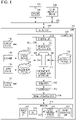
- Fig. 1 is a diagram illustrating the configuration of a system according to this embodiment.
- a multifunction printer (MFP) 101 which is a color image processing apparatus that uses cyan, magenta, yellow, and black (hereinafter referred to as "C, M, Y, and K") toner, is connected to other network-compatible devices through a network 123.
- a personal computer (PC) 124 is connected to the MFP 101 through the network 123.
- a printer driver 125 included in the PC 124 transmits print data to the MFP 101.
- a network interface (I/F) 122 receives print data and the like.
- a controller 102 includes a central processing unit (CPU) 103, a renderer 112, and an image processing unit 114.
- An interpreter 104 included in the CPU 103 interprets a page description language (PDL) portion of received print data, and generates intermediate language data 105.
- PDL page description language
- a CMS 106 performs color conversion using a source profile 107 and a destination profile 108 to generate intermediate language data (after the CMS) 111.
- the CMS refers to a "Color Management System", and performs color conversion using information regarding profiles that will be described later.
- the source profile 107 is a profile for converting a color space such as RGB or CMYK that depends on a device into a color space such as L*a*b* (hereinafter referred to as "Lab") or XYZ that has been defined by the International Commission on Illumination (CIE) and that does not depend on the device.
- CIE International Commission on Illumination
- XYZ is a color space that does not depend on the device, and represents colors using three types of stimulus values.
- the destination profile 108 is a profile for converting a device-independent color space into a CMYK color space that depends on the device (printer 115).
- a CMS 109 performs color conversion using a device link profile 110 to generate the intermediate language data (after the CMS) 111.
- the device link profile 110 is a profile for directly converting a device-dependent color space such as RGB or CMYK into a CMYK color space that depends on the device (printer 115). Whether the CMS 106 or the CMS 109 is selected depends on the setting of the printer driver 125.
- the plurality of CMSs (106 and 109) are used in accordance with the types of profiles (107, 108, and 110) in this embodiment, a plurality of types of profiles may be handled by a single CMS, instead.
- the types of profiles are not limited to the examples taken in this embodiment, but any type of profile may be used insofar as the device-dependent CMYK color space of the printer 115 is used.
- the renderer 112 generates a raster image 113 from the intermediate language data (after the CMS) 111.
- the image processing unit 114 performs image processing on the raster image 113 and an image read by a scanner 119. The image processing unit 114 will be described in detail later.
- the printer 115 connected to the controller 102 is a printer that forms a color image on a sheet of paper with color toner such as C, M, Y, and K using output data.
- the printer 115 includes a paper feed unit 116 that feeds sheets of paper, a paper discharge unit 117 that discharges sheets of paper on which images have been formed, and a color measuring unit 126.
- the color measuring unit 126 includes a sensor 127 thereof capable of obtaining spectral reflectance and values in a color space such as Lab or XYZ that does not depend on the device, and is controlled by a CPU 129 that controls the printer 115.
- the color measuring unit 126 measures the colors of patch images printed by the printer 115 on a recording medium such as a sheet of paper.
- Each of the patch images is an image for measuring a color having a uniform density and a certain area.
- a pattern image is obtained by generating a plurality of patch images whose colors are different and printing the generated patch images on a recording medium.
- the pattern image is read by the sensor 127 included in the color measuring unit 126, and read numerical information is transmitted to the controller 102.
- the controller 102 performs calculation using the numerical information, and uses results of the calculation when single-color calibration or multi-color calibration is executed.
- a display device 118 is a user interface (UI) that displays instructions to a user and the state of the MFP 101.
- the display device 118 is used when the single-color calibration or the multi-color calibration, which will be described later, is executed.
- the scanner 119 is a scanner including an automatic document feeder.
- the scanner 119 radiates light onto a stack of document images or a single document image using a light source, which is not illustrated, and forms a reflected document image on a solid-state imaging device such as a charge-coupled device (CCD) sensor using a lens. Thereafter, raster-like read image signals are obtained from the solid-state imaging device as image data.
- a solid-state imaging device such as a charge-coupled device (CCD) sensor using a lens.
- An input device 120 is an interface for receiving an input from the user. Part of the input device may be realized as a touch panel and incorporated into the display device 118.
- a storage device 121 saves data processed by the controller 102, data received by the controller 102, and the like.
- a color measuring device 128 is an external device for color measurement located in the network 123 or connected to the PC 124, and, as with the color measuring unit 126, is capable of obtaining spectral reflectance and values in a color space such as Lab or XYZ that does not depend on the device.
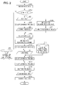
- Fig. 2 illustrates the procedure of image processing performed on the raster image 113 or an image read by the scanner 119.
- the procedure of processing illustrated in Fig. 2 is realized when executed by an application-specific integrated circuit (ASIC), which is not illustrated, included in the image processing unit 114.
- ASIC application-specific integrated circuit
- step S201 image data is received.
- step S202 whether the received data is scan data received from the scanner 119 or the raster image 113 transmitted from the printer driver 125 is determined.
- the received data is the raster image 113 that has been bitmapped by the renderer 112, and a CMYK image 211 has been obtained by converting, using a CMS, the raster image 113 into CMYK data that depends on the printer device.
- the received data is an RGB image 203, and therefore a color conversion process is performed in step S204 to generate a common RGB image 205.
- the common RGB image 205 is defined by an RGB color space that does not depend on the device, and can be converted into a device-independent color space such as Lab by calculation.
- step S206 a process for determining characters is performed to generate character determination data 207.
- the character determination data 207 is generated by detecting edges of an image or the like.
- step S208 a filtering process is performed on the common RGB image 205 using the character determination data 207.
- different filtering processes are performed for a character portion and other portions using the character determination data 207.
- step S209 a process for removing the background is performed in step S209 and a process for converting colors is performed in step S210 to generate the CMYK image 211 from which the background has been removed.
- a multi-color correction process is performed using a 4D-LUT 217.
- the 4D-LUT 217 is a four-dimensional LUT that converts a combination between signal values at a time when the C, M, Y, and K toner is output into a different combination between signal values of C, M, Y, and K.
- the 4D-LUT 217 is generated by the "multi-color calibration", which will be described later.
- “multi-colors” each of which is a color obtained by using a plurality of colors of toner, can be corrected.
- the image processing unit 114 corrects the tonal characteristics of single colors of C, M, Y, and K using a 1D-LUT 218 in step S213.
- the 1D-LUT 218 is a one-dimensional LUT that corrects colors (single colors) of C, M, Y, and K.
- the 1D-LUT 218 is generated by the "single-color calibration", which will be described later.
- step S214 the image processing unit 114 creates a CMYK image (binary) 215 by performing halftone processing such as screen processing or error diffusion processing, and in step S216, transmits image data to the printer 115.
- CMYK image binary
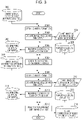
- the "single-color calibration" which corrects the tonal characteristics of the single colors output from the printer 115, will be described with reference to Fig. 3 .
- the color reproduction characteristics of the single colors such as maximum density characteristics and the tonal characteristics are corrected.
- the reproduction characteristics of colors corresponding to the C, M, Y, and K toner used by the printer 115 are simultaneously corrected when the calibration is executed. That is, the process illustrated in Fig. 3 is executed for the colors C, M, Y, and K at once.
- Fig. 3 illustrates a procedure of a process for creating the 1D-LUT 218 that corrects the tonal characteristics of single colors.
- the procedure of the process illustrated in Fig. 3 is realized when executed by the CPU 103, and the created 1D-LUT 218 is saved to the storage device 121.
- the display device 118 displays instructions to the user on the UI, and the input device 120 receives instructions from the user.
- step S301 chart data (A) 302 stored in the storage device 121 is obtained.
- the chart data (A) 302 is used for correcting the maximum density of each of the single colors, and includes signal values (for example, 255) at which maximum density data regarding the "single colors", namely C, M, Y, and K, are obtained.
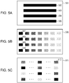
- step S303 the image processing unit 114 executes image processing on the chart data (A) 302, and the printer 115 prints a chart image (A) 304, which is a pattern image.
- An example is illustrated in Fig. 5A .
- An example 501 illustrated in Fig. 5A is an example at a time when the chart data (A) 302 has been printed, and patch images 502, 503, 504, and 505 are printed at the maximum densities of the colors of C, M, Y, and K, respectively.
- the chart image (A) 304 which is a pattern image, includes a plurality of patch images.
- the image processing unit 114 performs only the halftone processing, and does not perform the 1D-LUT correction process in step S213 or the 4D-LUT correction process in step S212.
- step S305 the densities of the printed chart image (A) 304 are measured by the scanner 119 or the sensor 127 included in the color measuring unit 126, and colorimetric values (A) 306 are obtained.
- the colorimetric values (A) 306 are density values of the colors of C, M, Y, and K.
- step S307 the maximum densities of the colorimetric values (A) 306 of the colors are corrected using the colorimetric values (A) 306 and predetermined target values (A) 308 of the maximum density values.
- device setting values of the printer 115 that is, for example, laser outputs, development biases, and the like are adjusted such that the maximum densities become close to the target values (A) 308.
- chart data (B) 310 stored in the storage device 121 is obtained.
- the chart data (B) 310 includes signal values of tonal data regarding the "single colors", namely C, M, Y, and K.
- An example 506 illustrated in Fig. 5B is an example of the printed chart image (B) 312 including the patch images printed on the recording medium using the chart data (B) 310.
- Patch images 507, 508, 509, and 510 and tonal data on the right illustrated in Fig. 5B are configured by tonal data regarding the colors of C, M, Y, and K.
- the chart image (B) 312, which is a pattern image includes a plurality of patch images.
- step S311 the image processing unit 114 executes image processing on the chart data (B) 310, and the printer 115 prints the chart image (B) 312.
- the image processing unit 114 performs only the halftone processing in step S214, and does not perform the 1D-LUT correction process in step S213 or the 4D-LUT correction process in step S212.
- the printer 115 has performed the maximum density correction in step S307, the maximum densities can now have substantially the same values as the target values (A) 308.
- step S313 the scanner 119 or the sensor 127 measures the colors to obtain colorimetric values (B) 314.
- the colorimetric values (B) 314 are density values obtained from the tones of the colors of C, M, Y, and K.
- step S315 the 1D-LUT 218, which corrects the tones of the single colors, is created using the colorimetric values (B) 314 and the predetermined target values (B) 316.
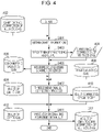
- the "multi-color calibration" which corrects the characteristics of multi-colors output from the printer 115, will be described with reference to Fig. 4 .
- the reproduction characteristics of multi-colors expressed by combinations (overlaps or the like) between a plurality of colors of toner are corrected.
- the following procedure of processing is realized when executed by the CPU 103 included in the controller 102.
- the obtained 4D-LUT 217 is saved to the storage device 121.
- the display device 118 displays instructions to the user on the UI, and the input device 120 receives instructions from the user.
- the multi-color calibration corrects the multi-colors output from the printer 115 after the single-color calibration is performed. Therefore, it is desirable to perform the multi-color calibration immediately after the single-color calibration is performed.
- step S401 information regarding chart data (C) 402 including "multi-colors" stored in the storage device 121 is obtained.
- the chart data (C) 402 is data for correcting the multi-colors, and includes signal values of the "multi-colors", which are combinations between C, M, Y, and K.
- the chart image (C) 404 which is a pattern image, includes a plurality of patch images.
- step S403 the image processing unit 114 executes image processing on the chart data (C) 402, and the printer 115 prints the chart image (C) 404. Since the multi-color calibration corrects the multi-color characteristics of the device after the single-color calibration is performed, the image processing unit 114 uses the 1D-LUT 218 created in the single-color calibration to execute the image processing.
- step S405 the multi-colors of the printed chart image (C) 404 are measured using the scanner 119 or the sensor 127 included in the color measuring unit 126 to obtain colorimetric values (C) 406.
- the colorimetric values (C) 406 indicate the multi-color characteristics of the printer 115 after the single-color calibration is performed.
- the colorimetric values (C) 406 are values in a color space that does not depend on the device, and the color space is Lab in this embodiment.
- RGB values are converted into Lab values using a 3D-LUT, which is not illustrated, or the like.
- step S407 a 3D-LUT 409 of Lab to CMY stored in the storage device 121 is obtained, and a 3D-LUT (corrected) 410 of Lab to CMY is created by reflecting differences between the colorimetric values (C) 406 and predetermined target values (C) 408.
- the 3D-LUT of Lab to CMY refers to a three-dimensional LUT that outputs CMY values corresponding to input Lab values.
- a specific method for creating the 3D-LUT (corrected) 410 of Lab to CMY will be described hereinafter.
- the differences between the colorimetric values (C) 406 and the predetermined target values (C) 408 are added to the input Lab values of the 3D-LUT 409 of Lab to CMY, and interpolation calculation is performed, using the 3D-LUT 409 of Lab to CMY, on the Lab values to which the differences have been added.
- the 3D-LUT (corrected) 410 of Lab to CMY is created.
- step S411 a 3D-LUT 412 of CMY to Lab stored in the storage device 121 is obtained, and calculation is performed using the 3D-LUT (corrected) 410 of Lab to CMY.
- the 4D-LUT 217 of CMYK to CMYK is created.
- the 3D-LUT of CMY to Lab is a three-dimensional LUT that outputs Lab values corresponding to input CMY values.
- a specific method for creating the 4D-LUT 217 of CMYK to CMYK will be described hereinafter.
- a 3D-LUT of CMY to CMY is created from the 3D-LUT 412 of CMY to Lab and the 3D-LUT (corrected) 410 of Lab to CMY.
- the 4D-LUT 217 of CMYK to CMYK is created such that an input value of K and an output value of K become the same.
- the 3D-LUT of CMY to CMY is a three-dimensional LUT that outputs corrected CMY values corresponding to input CMY values.
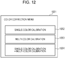
- Fig. 12 illustrates an example of UI display when the single-color calibration and the multi-color calibration are selectively executed.
- a UI screen 1201 illustrated in Fig. 12 is displayed on the display device 118.
- a button 1202 is a button for starting the single-color calibration and a button 1203 is a button for starting the multi-color calibration.
- a button 1204 is a button for starting calibration in which the multi-color calibration is executed after the single-color calibration is executed.
- the single-color calibration begins, and after completion of the single-color calibration, the multi-color calibration begins.
- the multi-color calibration begins.
- a button for starting the multi-color calibration may be displayed on the UI screen 1201 for the user and the multi-color calibration may begin when the button has been pressed by the user.
- buttons are used for the single-color calibration and the multi-color calibration.
- the chart image (C) 404 used in the execution of the multi-color calibration is printed, the 1D-LUT 218 created in the single-color calibration is used. Therefore, it is desirable to correct the reproduction characteristics of the multi-colors by performing the multi-color calibration immediately after the single-color calibration, that is, immediately after the color reproduction characteristics of the single colors are corrected.
- the two types of calibration are both executed, it takes time for the user to complete the processing of the calibration.
- either the single-color calibration or the multi-color calibration is executed in accordance with a use environment of the user.
- the execution frequencies of the two types of calibration become different. For example, the frequency of execution of the multi-color calibration of a user who frequently performs monochrome printing is low. On the other hand, the frequency of execution of the multi-color calibration of a user who frequently performs multi-color printing such as printing of photographs is high.
- timings at which this color correction menu can be selected may be controlled.
- control may be performed such that only the button 1204 can be selected.
- both the types of calibration have not been executed in a predetermined period of time
- control may be performed such that only the button 1204 can be selected.
- both the types of calibration have not been executed until printing is executed using a predetermined number of sheets of paper, control may be performed such that only the button 1204 can be selected.
- the single-color calibration and the multi-color calibration may be sequentially executed automatically when a predetermined period of time has elapsed, when printing has been executed using a predetermined number of sheets of paper, or when power has been supplied.
- control is performed such that only the button 1204 can be selected so that the multi-color calibration is executed immediately after the single-color calibration is executed at predetermined time intervals.
- Fig. 7 illustrates UIs necessary to realize this embodiment.
- An example of a 4D-LUT correction process setting screen 701 is displayed on the display device 118. This screen includes buttons for determining whether or not to execute the 4D-LUT correction process in S212 illustrated in Fig. 2 for a copy job, which handles scan data, and a print job, which handles electronic image data.
- the scan data is obtained when data obtained by reading a document using the scanner 119 has been transmitted to the MFP 101.
- the electronic image data is obtained when the input device 120 or the storage device 121 has transmitted data to the MFP 101.
- An “ON” button 702 is a button for determining that the 4D-LUT correction process is to be executed for the copy job.
- an “OFF” button 703 is a button for determining that the 4D-LUT correction process is not to be executed for the copy job.
- the "ON” button 702 and the “OFF” button 703 are exclusively selected.
- an “ON” button 704 is a button for determining that the 4D-LUT correction process S212 is to be executed for the print job.
- an “OFF” button 705 is a button for determining that the 4D-LUT correction process is not to be executed for the print job.
- the "ON” button 704 and the "OFF” button 705 are exclusively selected.
- An “OK” button 706 is a button used for returning to an arbitrary UI screen when this "4D-LUT correction process setting" has been completed.
- a “CANCEL” button 707 is a button used for returning to an arbitrary UI screen by canceling a change made to the setting.
- Fig. 6 is a flowchart illustrating a procedure of processing according to this embodiment.
- a control program which is not illustrated, for realizing this embodiment is stored in the storage device 121.
- the control program is loaded into a RAM, which is not illustrated, and executed by the CPU 103.
- S202 whether or not image data to be processed by the printer 115 is scan data is determined. If it is determined that the image data to be processed is scan data, the procedure proceeds to S600. In S600, scan image processing is performed to generate a CMYK image 211. The scan image processing executed in S600 is the same as the image processing performed in S204 to S210 illustrated in Fig. 2 . If it is determined in S202 that the image data to be processed is not scan data, the image data to be processed becomes a raster image 113 bitmapped by the renderer 112. This image data then becomes a CMYK image 211 when converted by a CMS into CMYK that depends on the printer device.
- control for switching a subsequent correction process in accordance with whether an image to be formed is obtained by executing a copy job or by executing a print job is performed. Therefore, next, in S601, whether or not the image data to be processed is scan data (that is, whether or not the image to be formed is obtained by executing a copy job) is determined again.
- the reason why the control for switching the correction process is performed is that an effect upon an image caused by correction values obtained by executing the multi-color calibration is different between when the image to be formed is obtained by executing a copy job and when the image to be formed is obtained by executing a print job.
- the degree of the effect upon the printed image caused by results of the correction is different between when the image has been obtained by executing a copy job and when the image has been obtained by executing a print job. That is, the effect upon a result of the printing caused by results of the correction performed by executing the multi-color calibration is larger when the image data to be processed is electronic image data than when the image data to be processed is scan image data.
- the temporarily saved image data has document management information, which includes information regarding the image data and settings for printing.
- the temporarily saved image data is read and whether or not the image data is scan data is determined on the basis of the document management information in S601.
- S601 If it is determined in S601 that the image data to be processed is scan data, it is determined that a job to be performed to form an image is a copy job, and the procedure proceeds to S602. In S602, 4D-LUT correction process settings for the copy job are checked on the 4D-LUT correction process setting screen 701. If the "ON" button 702 is selected in the settings, the procedure proceeds to S212. In S212, the 4D-LUT correction process is performed on the image data to be processed. That is, image processing (first processing) is performed using multi-color correction values obtained by executing the multi-color calibration.
- the 1D-LUT correction process is performed on the image data subjected to the 4D-LUT correction process.
- the procedure skips S212 and proceeds to S213. That is, image processing (second processing) is executed without using all the multi-color correction values obtained by executing the multi-color calibration.
- the 1D-LUT correction process is performed on the image data to be processed.
- the procedure skips S212 and proceeds to S213. That is, the image processing (second processing) is executed without using all the multi-color correction values obtained by executing the multi-color calibration.
- the 1D-LUT correction process is performed on the image data to be processed.
- output image processing is performed on all pieces of image data subjected to the 1D-LUT correction process in S213.
- the output image processing in S604 is the same as the processing performed in S214 and S216 illustrated in Fig. 2 .
- a predetermined correction process can be performed on the image data to be processed when the image data to be processed is to be copied and when the image data to be processed is to be printed. That is, control can be performed such that the first processing and the second processing are selectively executed when the image data to be processed is to be copied and when the image data to be processed is to be printed.
- the correction process using the 4D-LUT is skipped in S602 and S603 when the 4D-LUT correction process setting is "OFF"
- the correction process need not be skipped, and the correction may be performed using not the entirety of the 4D-LUT but part of the 4D-LUT. That is, the correction may be performed without using at least some of the multi-color correction values obtained by executing the multi-color calibration.
- patch images are created in the chart image (C) 404 created in Fig. 4 by printing only limited colors (colors that are not relevant to the continuity of tone), and a 4D-LUT (partial) is created by reading the limited number of patch images.
- the multi-color calibration is executed on the colors that are not relevant to the continuity of tone, thereby increasing the correction accuracy.
- the correction may be performed using predetermined alternative correction values instead of the correction values obtained by executing the multi-color calibration.
- the alternative correction values include data capable of correcting only the colors that are not relevant to the continuity of tone.
- a timing at which the 4D-LUT correction processing setting is performed on the 4D-LUT correction process setting screen 701 may be set by the user as an arbitrary timing.
- the setting timing may be incorporated into the procedure for performing the single-color calibration and the multi-color calibration.
- the button 1204 has been pressed in the screen illustrated in Fig. 12 .
- the single-color calibration and the multi-color calibration are treated as a series of processes.
- the 4D-LUT correction process setting screen 701 may be displayed after the multi-color calibration is completed.
- the 4D-LUT correction process setting screen 701 may be displayed before the single-color calibration is executed.
- the 4D-LUT correction process setting screen 701 may be displayed before or after the multi-color calibration is executed.
- a setting screen may be displayed to prompt the user to set the 4D-LUT correction process.
- the settings in the display screen may always be reset to initial values, or may reflect previous settings.
- the 4D-LUT correction process setting screen 701 may be displayed before or after the single-color calibration is executed.
- the 4D-LUT correction process setting screen 701 may be displayed with the "OFF" button 703 and the "OFF" button 705 selected, in order to have the user confirm that image processing using results of the multi-color calibration is not to be executed.
- the 4D-LUT correction process setting screen 701 is effective to display the 4D-LUT correction process setting screen 701 in accordance with a state at a time when the multi-color calibration has been executed. For example, when a long time has elapsed since data indicating the target values (C) 408 used for executing the multi-color calibration illustrated in Fig. 4 was stored, the amount of correction is expected to be large due to changes in the printer 115 over time. When a large amount of correction is performed, differences between target values and colorimetric values become large, thereby making it more likely to lose the continuity of tone in the image.
- the 4D-LUT correction process setting screen 701 may be displayed to prompt the user to perform image processing without using results of the correction performed by executing the multi-color calibration (without setting the 4D-LUT correction process).
- the 4D-LUT correction process setting screen 701 may be displayed to prompt the user to set the 4D-LUT correction process.
- the 4D-LUT correction process setting screen 701 may be displayed to prompt the user to set the 4D-LUT correction process.
- an N-th (or N-th or later) operation of correction has been executed using the same target values (C) 408, the 4D-LUT correction process setting screen 701 may be displayed to prompt the user to set the 4D-LUT correction process.
- the user may be prompted to set the 4D-LUT correction process at this timing.
- the 4D-LUT correction process setting screen 701 may be displayed after the calibration is executed by prompting the user to execute the calibration.
- the 4D-LUT correction process setting screen 701 may be displayed to prompt the user to set the 4D-LUT correction process.
- whether or not to apply results of the correction obtained by executing the multi-color calibration to the formation of an image may be determined in consideration of whether the image data to be processed by the printer 115 is electronic image data or scan image data.
- control may be performed such that the first processing and the second processing for correcting the reproduction characteristics are selectively executed when an image is formed.
- the user may be prompted to make settings, thereby suppressing occurrence of a problem in the continuity of tone in image data to be printed.
- Fig. 8 is an example of a UI screen according to this embodiment. Since, unlike the first embodiment, whether or not to execute the 4D-LUT correction process is determined only when a print job for printing image data to be processed is to be executed, no setting buttons for each type of job such as those in the screen illustrated in Fig. 7 are included.
- a setting screen 801 has a simplest possible configuration when only an item relating to the 4D-LUT correction process performed using the printer driver 125 or the remote UI screen is taken into consideration.
- the setting screen 801 includes a button 802 used for setting the 4D-LUT correction to "ON" and a button 803 used for setting the 4D-LUT correction process to "OFF".
- the "ON" button 802 and the "OFF” button 803 are exclusively selected.
- the "OK” button 706 and the “CANCEL” button 707 may be displayed as in the 4D-LUT correction process setting screen 701.
- an "automatic” button which is not illustrated, may be added, and a method in which a predetermined setting of the MFP 101 is followed when the "automatic" button has been selected may be added.
- the correction may be performed using the 4D-LUT (partial) as described above.
- the correction is performed using the 4D-LUT (partial), and then the 1D-LUT correction process is performed.
- information necessary for the user to determine whether to set the 4D-LUT correction process to "ON” or “OFF” is obtained from the controller 102 through the network 123.
- the information may always be displayed, or may be displayed when obtained from the controller 102 in accordance with a request from the user.
- the information to be displayed includes, for example, a date and time at which a latest operation of the multi-color calibration has been performed and the target values (C) 408 used. If a long time has elapsed since a previous operation of the multi-color calibration was performed, it is likely that parameters (that is, the correction values obtained by executing the multi-color calibration) indicated by the 4D-LUT 217 are not appropriate. Therefore, it can be expected that the continuity of tone in an image is lost if an image to be printed is corrected using the 4D-LUT 217.
- the user can appropriately select whether to set the 4D-LUT correction process to "ON” or "OFF".
- the user may determine that the continuity of tone in an image to be printed is high through a visual check, and set the 4D-LUT correction process to "OFF". As described above, whether or not to execute the 4D-LUT correction process S212 is determined using the printer driver 125, the remote UI screen, or the like.
- whether or not to use results of the multi-color calibration can be switched in accordance with the state of the MFP 101 and the characteristics of an image to be printed each time an image is formed by executing a print job.
- Fig. 10 is a flowchart illustrating a procedure of a process for automatically switching whether or not to execute the 4D-LUT correction process, which is a characteristic of this embodiment.
- a control program which is not illustrated, for realizing this embodiment is stored in the storage device 121.
- the control program is loaded into the RAM, which is not illustrated, and executed by the CPU 103. The characteristics of this method will be described with reference to the procedure illustrated in the flowchart of Fig. 10 .
- the procedure proceeds to S1002.
- whether or not a gradation image is included in the image is determined.
- the determination as to whether or not a gradation image is included is made by analyzing image data to be processed, attribute data accompanying the image data, the intermediate language data 105, or the like. For example, if there is an object specified as gradation in the intermediate language data 105, it is determined that a gradation image is included in the image to be printed. Any other method that is effective in determining whether or not gradation is included may be used.
- the procedure proceeds to S1003. If it is determined in S1002 that a gradation image is included, it is determined in S1003 that the execution of the 4D-LUT correction process is to be set to "OFF”, and the procedure proceeds to S1005. In S1005, the execution of the 4D-LUT correction process is set to "OFF". That is, the second processing is set.
- the correction may be performed using the above-described 4D-LUT (partial). In this case, the correction is performed using the 4D-LUT (partial), and then the 1D-LUT correction process is performed.
- UIs illustrated in Fig. 9 may be displayed in a screen of the PC 124 or a screen of the display device 118.
- a UI screen 901 is an example of a UI for switching whether or not to automatically determine the presence of a gradation image included in the image to be printed.
- An "ON" button 902 determines that an automatic determination as to the presence of a gradation image is to be executed.
- an “OFF” button 903 determines that an automatic determination as to the presence of a gradation image is not to be executed.
- the "ON” button 902 and the "OFF” button 903 are exclusively selected.
- An “OK” button 904 is used for returning to an arbitrary UI screen when setting has been completed.
- a "CANCEL” button 905 is used for returning to an arbitrary UI screen by canceling a change made to the setting.
- the switching of the automatic determination is effective when, for example, the accuracy with which whether or not a gradation image is included in the image to be printed is determined is not perfect or when an erroneous determination frequently occurs due to conditions such as an application used by the user and the image data to be printed.
- a process performed when the automatic determination switching screen 901 is set to "ON” is as described with reference to Fig. 10 . Therefore, only a process performed when the automatic determination switching screen 901 is set to "OFF” is described with reference to Fig. 11 .
- S1001 If it is determined in S1001 that the specified job is not a scan job (that is, the specified job is a print job), whether or not to automatically determine the presence of a gradation image in the image to be printed is checked in S1101. If the automatic determination is to be performed, that is, if the automatic determination switching screen 901 is set to "ON”, the above-described process is performed. If it is determined in S1101 that the automatic determination is not to be performed, that is, if the automatic determination switching screen 901 is set to "OFF”, the process proceeds to S1102. In S1102, a predetermined setting is checked.
- the correction may be performed using the above-described 4D-LUT (partial). In this case, the correction is performed using the 4D-LUT (partial), and then the 1D-LUT correction process is performed.
- control is performed such that, if it is determined that the 4D-LUT correction process is not to be executed, the multi-color calibration is not executed.
- the execution of the 4D-LUT correction process is set to "OFF" when a copy job is to be executed or when the print job is to be executed, the correction using the 4D-LUT is not performed during processing of an image even if correction values are obtained by executing the multi-color calibration. Therefore, the effect of the correction that would otherwise be produced by the multi-color calibration is not obtained. In this case, the execution of the multi-color calibration itself is wasted, and accordingly the execution of the multi-color calibration is inhibited on the display device 118. Alternatively, when the multi-color calibration has begun, the user may be informed that the correction process is not effective.
- the present invention may be realized by executing the following process. That is, the present invention may be realized by executing a process executed by supplying software (program) for realizing the functions of the above-described embodiments to a system or an apparatus through a network or one of various storage media and reading the program using a computer (or a CPU, a microprocessor unit (MPU), or the like) of the system or the apparatus.
- software program
- MPU microprocessor unit
- Embodiments of the present invention can also be realized by a computer of a system or apparatus that reads out and executes computer executable instructions recorded on a storage medium (e.g., non-transitory computer-readable storage medium) to perform the functions of one or more of the above-described embodiment(s) of the present invention, and by a method performed by the computer of the system or apparatus by, for example, reading out and executing the computer executable instructions from the storage medium to perform the functions of one or more of the above-described embodiment(s).
- the computer may comprise one or more of a central processing unit (CPU), micro processing unit (MPU), or other circuitry, and may include a network of separate computers or separate computer processors.
- the computer executable instructions may be provided to the computer, for example, from a network or the storage medium.
- the storage medium may include, for example, one or more of a hard disk, a random-access memory (RAM), a read only memory (ROM), a storage of distributed computing systems, an optical disk (such as a compact disc (CD), digital versatile disc (DVD), or Blu-ray Disc (BD) TM ), a flash memory device, a memory card, and the like.
Landscapes
- Engineering & Computer Science (AREA)
- Multimedia (AREA)
- Signal Processing (AREA)
- General Engineering & Computer Science (AREA)
- Physics & Mathematics (AREA)
- General Physics & Mathematics (AREA)
- Theoretical Computer Science (AREA)
- Facsimile Image Signal Circuits (AREA)
- Image Processing (AREA)
- Color Image Communication Systems (AREA)
Claims (14)
- Farbbildverarbeitungsvorrichtung (101), umfassend:eine erste Beschaffungseinrichtung (114), die ausgelegt ist, monochromatische Korrekturdaten unter Verwendung von Ergebnissen einer Messung von Farben von monochromatischen Patchbildern zu beschaffen, wobei ein jeweiliges Patchbild durch eine Bilderzeugungseinrichtung (115) unter ausschließlicher Verwendung eines monochromatischen Aufzeichnungsmaterials erzeugt wird;eine zweite Beschaffungseinrichtung (114), die ausgelegt ist, Mehrfarb-Korrekturdaten unter Verwendung von Ergebnissen der Messung von Farben von mehrfarbigen Patchbildern zu beschaffen, wobei ein jeweiliges Patchbild durch die Bilderzeugungseinrichtung (115) unter Verwendung von mindestens zwei Farbaufzeichnungsmaterialien erzeugt wird;eine erste Verarbeitungseinrichtung (114), die ausgelegt ist, zuerst einen Korrekturprozess unter Verwendung der durch die zweite Beschaffungseinrichtung (114) beschafften Mehrfarb-Korrekturdaten auszuführen, und dann einen Korrekturprozess unter Verwendung der durch die erste Beschaffungseinrichtung (114) beschafften monochromatischen Korrekturdaten auszuführen;eine zweite Verarbeitungseinrichtung (114), die ausgelegt ist, falls die Bilderzeugungseinrichtung ein Farbbild erzeugt, den Korrekturprozess auszuführen unter Verwendung der durch die erste Beschaffungseinrichtung (114) beschafften monochromatischen Korrekturdaten und nicht der durch die zweite Beschaffungseinrichtung (114) beschafften Mehrfarb-Korrekturdaten; undeine Steuerungseinrichtung (114), die ausgelegt ist, die erste Verarbeitungseinrichtung (114) und die zweite Verarbeitungseinrichtung (114) selektiv zu implementieren, falls die Bilderzeugungseinrichtung (115) das Farbbild erzeugt;wobei die Steuerungseinrichtung (114) eine erste Einstellung für einen Kopierauftrag für mindestens den durch die erste Verarbeitungseinrichtung auszuführenden Korrekturprozess oder den durch die zweite Verarbeitungseinrichtung auszuführenden Korrekturprozess über eine Bedienungseinheit vornimmt; undwobei die Steuerungseinrichtung (114) eine zweite Einstellung für einen Druckauftrag für mindestens den durch die erste Verarbeitungseinrichtung auszuführenden Korrekturprozess oder den durch die zweite Verarbeitungseinrichtung auszuführenden Korrekturprozess über die Bedienungseinheit vornimmt.
- Farbbildverarbeitungsvorrichtung (101) nach Anspruch 1, ferner umfassend:
eine Anzeigeeinrichtung (118), die ausgelegt ist, einen Bildschirm zum Vornehmen von Einstellungen für die durch die Steuerungseinrichtung (114) ausgeführte Verarbeitung anzuzeigen. - Farbbildverarbeitungsvorrichtung (101) nach Anspruch 1 oder 2,wobei, falls ein durch die Bilderzeugungseinrichtung (115) erzeugtes Farbbild durch Ausführen eines Druckauftrags beschafft wird, die Steuerungseinrichtung (114) konfiguriert ist, die zweite Verarbeitungseinrichtung zu veranlassen, zu arbeiten, undwobei, falls ein durch die Bilderzeugungseinrichtung (115) erzeugtes Farbbild durch Ausführen eines Kopierauftrags beschafft wird, die Steuerungseinrichtung (114) konfiguriert ist, die erste Verarbeitungseinrichtung zu veranlassen, zu arbeiten.
- Farbbildverarbeitungsvorrichtung (101) nach Anspruch 1 oder 2,
wobei die Steuerungseinrichtung (114) so eingestellt werden kann, dass sie einem Benutzer ermöglicht, falls ein durch die Bilderzeugungseinrichtung (115) erzeugtes Farbbild durch Ausführen eines Druckauftrags beschafft wird, zu wählen, ob die Steuerungseinrichtung die erste Verarbeitungseinrichtung veranlasst, zu arbeiten, oder ob die Steuerungseinrichtung die zweite Verarbeitungseinrichtung veranlasst, zu arbeiten. - Farbbildverarbeitungsvorrichtung (101) nach Anspruch 1, wobei die Steuerungseinrichtung (114) so eingestellt werden kann, dass sie einem Benutzer ermöglicht, falls ein durch die Bilderzeugungseinrichtung (115) erzeugtes Farbbild durch Ausführen eines Kopierauftrags beschafft wird, zu wählen, ob die Steuerungseinrichtung die erste Verarbeitungseinrichtung veranlasst, zu arbeiten, oder ob die Steuerungseinrichtung die zweite Verarbeitungseinrichtung veranlasst, zu arbeiten.
- Farbbildverarbeitungsvorrichtung (101) nach einem der vorhergehenden Ansprüche,
wobei die Steuerungseinrichtung (114) für einen jeweiligen Druckauftrag, der von einer mit der Farbbildverarbeitungsvorrichtung verbundenen Informationsverarbeitungsvorrichtung (124) übertragen wird, die erste Verarbeitungseinrichtung und die zweite Verarbeitungseinrichtung selektiv veranlasst, zu arbeiten. - Farbbildverarbeitungsvorrichtung (101) nach einem der vorhergehenden Ansprüche,
wobei die Steuerungseinrichtung (114) für eine jeweilige in einem Farbbild enthaltene Seite die erste Verarbeitungseinrichtung und die zweite Verarbeitungseinrichtung selektiv veranlasst, zu arbeiten. - Farbbildverarbeitungsvorrichtung nach Anspruch 1, wobei die Steuerungseinrichtung (114) so konfiguriert ist, dass, falls ein durch die Bilderzeugungseinrichtung (115) erzeugtes Farbbild ein Gradationsbild enthält, die Steuerungseinrichtung die erste Verarbeitungseinrichtung nicht veranlasst, zu arbeiten, und die zweite Verarbeitungseinrichtung veranlasst, zu arbeiten.
- Farbbildverarbeitungsvorrichtung nach einem der vorhergehenden Ansprüche,
wobei, falls die Steuerungseinrichtung (114) die erste Verarbeitungseinrichtung nicht veranlasst, zu arbeiten, und die zweite Verarbeitungseinrichtung veranlasst, zu arbeiten, die Beschaffungseinrichtung die Korrekturwerte nicht beschafft, die verwendet werden, um zu veranlassen, dass die Reproduktionseigenschaften der durch die Bilderzeugungseinrichtung (115) erzeugten Mehrfarben nahe an den Zielwerten liegen. - Verfahren zum Verarbeiten eines Farbbilds, wobei das Verfahren die folgenden Schritte umfasst:einen ersten Beschaffungsschritt des Beschaffens monochromatischer Korrekturdaten unter Verwendung von Ergebnissen einer Messung von Farben von monochromatischen Patchbildern, wobei ein jeweiliges Patchbild durch eine Bilderzeugungseinrichtung (115) unter ausschließlicher Verwendung eines monochromatischen Aufzeichnungsmaterials erzeugt wird;einen zweiten Beschaffungsschritt des Beschaffens von Mehrfarb-Korrekturdaten unter Verwendung von Ergebnissen einer Messung von Farben von mehrfarbigen Patchbildern, wobei ein jeweiliges Patchbild durch die Bilderzeugungseinrichtung (115) unter Verwendung von mindestens zwei Farbaufzeichnungsmaterialien erzeugt wird; undfalls die Bilderzeugungseinrichtung (115) das Farbbild erzeugt, selektives Ausführen entweder eines ersten Verarbeitungsschritts, der einen Korrekturprozess unter Verwendung der Mehrfarb-Korrekturdaten enthält, die durch den zweiten Beschaffungsschritt beschafft werden, und dann Ausführen eines Korrekturprozesses unter Verwendung der monochromatischen Korrekturdaten, die durch den ersten Beschaffungsschritt beschafft werden, oderAusführen eines zweiten Verarbeitungsschritts, falls die Bilderzeugungseinrichtung ein Farbbild erzeugt, der einen Korrekturprozess unter Verwendung der monochromatischen Korrekturdaten enthält, die durch den ersten Beschaffungsschritt beschafft werden;Vornehmen einer ersten Einstellung für einen Kopierauftrag für mindestens den durch den ersten Verarbeitungsschritt auszuführenden Korrekturprozess oder den durch den zweiten Verarbeitungsschritt auszuführenden Korrekturprozess über eine Bedienungseinheit; undVornehmen einer zweiten Einstellung für einen Druckauftrag für mindestens den durch den ersten Verarbeitungsschritt auszuführenden Korrekturprozess oder den durch den zweiten Verarbeitungsschritt auszuführenden Korrekturprozess über die Bedienungseinheit.
- Verfahren nach Anspruch 10, ferner umfassend den folgenden Schritt:
Veranlassen einer Anzeigeeinrichtung (118), einen Bildschirm zum Vornehmen von Einstellungen für die im Schritt des selektiven Ausführens ausgeführte Verarbeitung anzuzeigen. - Verfahren nach Anspruch 10 oder 11,wobei, falls ein durch die Bilderzeugungseinrichtung (115) erzeugtes Farbbild durch Ausführen eines Druckauftrags beschafft wird, im Schritt des selektiven Ausführens der zweite Verarbeitungsschritt ausgeführt wird, undwobei, falls ein durch die Bilderzeugungseinrichtung (115) erzeugtes Farbbild durch Ausführen eines Kopierauftrags beschafft wird, im Schritt des selektiven Ausführens der erste Verarbeitungsschritt ausgeführt wird.
- Programm, das, wenn es durch eine Farbbildverarbeitungsvorrichtung ausgeführt wird, die Bildverarbeitungsvorrichtung veranlasst, ein Verfahren nach einem der Ansprüche 10 bis 12 durchzuführen.
- Speichermedium, das ein Programm nach Anspruch 13 speichert.
Applications Claiming Priority (1)
| Application Number | Priority Date | Filing Date | Title |
|---|---|---|---|
| JP2013043044A JP6193589B2 (ja) | 2013-03-05 | 2013-03-05 | 画像処理装置及び画像処理方法ならびに画像処理方法を実行するプログラム |
Publications (3)
| Publication Number | Publication Date |
|---|---|
| EP2775699A2 EP2775699A2 (de) | 2014-09-10 |
| EP2775699A3 EP2775699A3 (de) | 2018-01-03 |
| EP2775699B1 true EP2775699B1 (de) | 2022-10-19 |
Family
ID=50287858
Family Applications (1)
| Application Number | Title | Priority Date | Filing Date |
|---|---|---|---|
| EP14157323.8A Active EP2775699B1 (de) | 2013-03-05 | 2014-02-28 | Farbbildverarbeitungsvorrichtung, Verfahren zur Farbbildverarbeitung und Programm zur Ausführung des Verfahrens zur Farbbildverarbeitung |
Country Status (5)
| Country | Link |
|---|---|
| US (2) | US8958128B2 (de) |
| EP (1) | EP2775699B1 (de) |
| JP (1) | JP6193589B2 (de) |
| KR (1) | KR101707834B1 (de) |
| CN (1) | CN104038665B (de) |
Families Citing this family (11)
| Publication number | Priority date | Publication date | Assignee | Title |
|---|---|---|---|---|
| JP5990093B2 (ja) | 2012-11-29 | 2016-09-07 | キヤノン株式会社 | 画像処理装置、画像処理方法ならびにプログラム |
| JP6311283B2 (ja) * | 2013-11-13 | 2018-04-18 | 富士ゼロックス株式会社 | 画像読取装置及びプログラム |
| KR102254830B1 (ko) | 2015-01-30 | 2021-05-24 | 휴렛-팩커드 디벨롭먼트 컴퍼니, 엘.피. | 색 보정 |
| WO2017184151A1 (en) | 2016-04-21 | 2017-10-26 | Hewlett-Packard Development Company, L.P. | Colorant calibration utilizing calibration element |
| CN106937018B (zh) * | 2017-01-12 | 2019-03-05 | 浙江大学 | 基于rbf神经网络用于纺织品喷墨印染的色彩映射方法 |
| JP6862267B2 (ja) * | 2017-05-02 | 2021-04-21 | キヤノン株式会社 | 色変換ルックアップテーブルの作成装置、色変換ルックアップテーブルの作成方法およびプログラム |
| JP6567012B2 (ja) * | 2017-09-28 | 2019-08-28 | キヤノン株式会社 | 情報処理装置、情報処理方法、およびプログラム |
| KR20190111693A (ko) * | 2018-03-23 | 2019-10-02 | 휴렛-팩커드 디벨롭먼트 컴퍼니, 엘.피. | 색상 프로파일 배포 및 관리 |
| JP2021093719A (ja) * | 2019-12-09 | 2021-06-17 | キヤノン株式会社 | 画像処理装置、画像処理方法、およびプログラム |
| JP2022006643A (ja) * | 2020-06-24 | 2022-01-13 | キヤノン株式会社 | 印刷装置とその制御方法、及びプログラム |
| CN115705663B (zh) * | 2021-08-10 | 2023-11-14 | 荣耀终端有限公司 | 图像处理方法与电子设备 |
Citations (1)
| Publication number | Priority date | Publication date | Assignee | Title |
|---|---|---|---|---|
| US20100321747A1 (en) * | 2009-06-18 | 2010-12-23 | Fuji Xerox Co., Ltd. | Image processing apparatus, image forming system, image processing method and computer readable medium |
Family Cites Families (12)
| Publication number | Priority date | Publication date | Assignee | Title |
|---|---|---|---|---|
| JP2002123055A (ja) * | 2000-10-18 | 2002-04-26 | Ricoh Co Ltd | 画像形成装置におけるキャリブレーション方法 |
| JP2003224723A (ja) * | 2002-01-29 | 2003-08-08 | Ricoh Co Ltd | カラー画像出力装置のカラーキャリブレーション方式、およびそれを備えたカラー画像出力装置 |
| US7639392B2 (en) * | 2003-03-28 | 2009-12-29 | Infoprint Solutions Company, Llc | Methods, systems, and media to enhance image processing in a color reprographic system |
| JP2007150757A (ja) * | 2005-11-28 | 2007-06-14 | Canon Inc | 画像処理装置、画像処理装置の制御方法、コンピュータプログラム及び記憶媒体 |
| JP4677379B2 (ja) * | 2006-07-28 | 2011-04-27 | キヤノン株式会社 | 画像処理装置及び画像処理方法 |
| JP4766691B2 (ja) * | 2006-12-18 | 2011-09-07 | キヤノン株式会社 | 階調補正テーブル作成方法及び装置 |
| JP4838702B2 (ja) * | 2006-12-26 | 2011-12-14 | キヤノン株式会社 | 画像処理装置、その制御方法及びプログラム |
| JP4996309B2 (ja) * | 2007-04-03 | 2012-08-08 | キヤノン株式会社 | カラー画像処理システム及び方法 |
| JP4434250B2 (ja) * | 2007-09-21 | 2010-03-17 | ソニー株式会社 | 画像信号処理回路、撮像装置、および画像信号処理方法、並びにコンピュータ・プログラム |
| JP4640453B2 (ja) * | 2008-06-19 | 2011-03-02 | コニカミノルタビジネステクノロジーズ株式会社 | 原稿読み取り装置、原稿読み取りプログラム、原稿読み取り方法 |
| JP5267806B2 (ja) * | 2009-05-01 | 2013-08-21 | 株式会社リコー | キャリブレーション装置、キャリブレーション方法、プログラムおよび記録媒体 |
| JP5631060B2 (ja) * | 2010-06-03 | 2014-11-26 | キヤノン株式会社 | 画像処理装置及び画像処理方法ならびに画像処理方法を実行するプログラム |
-
2013
- 2013-03-05 JP JP2013043044A patent/JP6193589B2/ja active Active
-
2014
- 2014-02-28 EP EP14157323.8A patent/EP2775699B1/de active Active
- 2014-03-03 CN CN201410075160.2A patent/CN104038665B/zh active Active
- 2014-03-04 KR KR1020140025308A patent/KR101707834B1/ko active IP Right Grant
- 2014-03-04 US US14/197,168 patent/US8958128B2/en active Active
-
2015
- 2015-01-08 US US14/592,035 patent/US9094642B2/en active Active
Patent Citations (1)
| Publication number | Priority date | Publication date | Assignee | Title |
|---|---|---|---|---|
| US20100321747A1 (en) * | 2009-06-18 | 2010-12-23 | Fuji Xerox Co., Ltd. | Image processing apparatus, image forming system, image processing method and computer readable medium |
Also Published As
| Publication number | Publication date |
|---|---|
| KR101707834B1 (ko) | 2017-02-17 |
| US20140253931A1 (en) | 2014-09-11 |
| KR20140109322A (ko) | 2014-09-15 |
| US9094642B2 (en) | 2015-07-28 |
| JP6193589B2 (ja) | 2017-09-06 |
| EP2775699A3 (de) | 2018-01-03 |
| JP2014171177A (ja) | 2014-09-18 |
| EP2775699A2 (de) | 2014-09-10 |
| US20150124272A1 (en) | 2015-05-07 |
| US8958128B2 (en) | 2015-02-17 |
| CN104038665B (zh) | 2017-03-01 |
| CN104038665A (zh) | 2014-09-10 |
Similar Documents
| Publication | Publication Date | Title |
|---|---|---|
| EP2775699B1 (de) | Farbbildverarbeitungsvorrichtung, Verfahren zur Farbbildverarbeitung und Programm zur Ausführung des Verfahrens zur Farbbildverarbeitung | |
| US11831847B2 (en) | Image processing apparatus, image processing method, and program for forming correcting color image data for each paper type | |
| US9836676B2 (en) | Color image processing apparatus, control method therefor, and program for executing image processing method | |
| JP5968132B2 (ja) | 画像処理装置、画像処理方法ならびにプログラム | |
| US9159001B2 (en) | Device, method, and recording medium for controlling image forming apparatus | |
| KR101672075B1 (ko) | 화상 처리 장치, 화상 처리 방법 및 컴퓨터 판독가능 저장매체 | |
| JP5984530B2 (ja) | 画像処理装置、画像処理方法、およびそのプログラム | |
| JP2014099830A (ja) | カラー画像処理装置及び画像処理方法ならびに画像処理方法を実行するプログラム | |
| JP6239080B2 (ja) | 画像形成装置、及びその制御方法ならびにコンピュータプログラム | |
| JP6526134B2 (ja) | 画像形成装置、及びその制御方法ならびにコンピュータプログラム | |
| JP6041633B2 (ja) | カラー画像処理装置及びその制御方法ならびに画像処理方法を実行するプログラム |
Legal Events
| Date | Code | Title | Description |
|---|---|---|---|
| PUAI | Public reference made under article 153(3) epc to a published international application that has entered the european phase |
Free format text: ORIGINAL CODE: 0009012 |
|
| 17P | Request for examination filed |
Effective date: 20140228 |
|
| AK | Designated contracting states |
Kind code of ref document: A2 Designated state(s): AL AT BE BG CH CY CZ DE DK EE ES FI FR GB GR HR HU IE IS IT LI LT LU LV MC MK MT NL NO PL PT RO RS SE SI SK SM TR |
|
| AX | Request for extension of the european patent |
Extension state: BA ME |
|
| PUAL | Search report despatched |
Free format text: ORIGINAL CODE: 0009013 |
|
| AK | Designated contracting states |
Kind code of ref document: A3 Designated state(s): AL AT BE BG CH CY CZ DE DK EE ES FI FR GB GR HR HU IE IS IT LI LT LU LV MC MK MT NL NO PL PT RO RS SE SI SK SM TR |
|
| AX | Request for extension of the european patent |
Extension state: BA ME |
|
| RIC1 | Information provided on ipc code assigned before grant |
Ipc: H04N 1/60 20060101AFI20171130BHEP |
|
| STAA | Information on the status of an ep patent application or granted ep patent |
Free format text: STATUS: REQUEST FOR EXAMINATION WAS MADE |
|
| R17P | Request for examination filed (corrected) |
Effective date: 20180703 |
|
| RBV | Designated contracting states (corrected) |
Designated state(s): AL AT BE BG CH CY CZ DE DK EE ES FI FR GB GR HR HU IE IS IT LI LT LU LV MC MK MT NL NO PL PT RO RS SE SI SK SM TR |
|
| STAA | Information on the status of an ep patent application or granted ep patent |
Free format text: STATUS: EXAMINATION IS IN PROGRESS |
|
| 17Q | First examination report despatched |
Effective date: 20200421 |
|
| STAA | Information on the status of an ep patent application or granted ep patent |
Free format text: STATUS: EXAMINATION IS IN PROGRESS |
|
| GRAP | Despatch of communication of intention to grant a patent |
Free format text: ORIGINAL CODE: EPIDOSNIGR1 |
|
| STAA | Information on the status of an ep patent application or granted ep patent |
Free format text: STATUS: GRANT OF PATENT IS INTENDED |
|
| INTG | Intention to grant announced |
Effective date: 20220518 |
|
| GRAS | Grant fee paid |
Free format text: ORIGINAL CODE: EPIDOSNIGR3 |
|
| GRAA | (expected) grant |
Free format text: ORIGINAL CODE: 0009210 |
|
| STAA | Information on the status of an ep patent application or granted ep patent |
Free format text: STATUS: THE PATENT HAS BEEN GRANTED |
|
| AK | Designated contracting states |
Kind code of ref document: B1 Designated state(s): AL AT BE BG CH CY CZ DE DK EE ES FI FR GB GR HR HU IE IS IT LI LT LU LV MC MK MT NL NO PL PT RO RS SE SI SK SM TR |
|
| REG | Reference to a national code |
Ref country code: GB Ref legal event code: FG4D |
|
| REG | Reference to a national code |
Ref country code: CH Ref legal event code: EP |
|
| REG | Reference to a national code |
Ref country code: IE Ref legal event code: FG4D |
|
| REG | Reference to a national code |
Ref country code: DE Ref legal event code: R096 Ref document number: 602014085241 Country of ref document: DE |
|
| REG | Reference to a national code |
Ref country code: AT Ref legal event code: REF Ref document number: 1526283 Country of ref document: AT Kind code of ref document: T Effective date: 20221115 |
|
| REG | Reference to a national code |
Ref country code: LT Ref legal event code: MG9D |
|
| REG | Reference to a national code |
Ref country code: NL Ref legal event code: MP Effective date: 20221019 |
|
| REG | Reference to a national code |
Ref country code: AT Ref legal event code: MK05 Ref document number: 1526283 Country of ref document: AT Kind code of ref document: T Effective date: 20221019 |
|
| PG25 | Lapsed in a contracting state [announced via postgrant information from national office to epo] |
Ref country code: NL Free format text: LAPSE BECAUSE OF FAILURE TO SUBMIT A TRANSLATION OF THE DESCRIPTION OR TO PAY THE FEE WITHIN THE PRESCRIBED TIME-LIMIT Effective date: 20221019 |
|
| PG25 | Lapsed in a contracting state [announced via postgrant information from national office to epo] |
Ref country code: SE Free format text: LAPSE BECAUSE OF FAILURE TO SUBMIT A TRANSLATION OF THE DESCRIPTION OR TO PAY THE FEE WITHIN THE PRESCRIBED TIME-LIMIT Effective date: 20221019 Ref country code: PT Free format text: LAPSE BECAUSE OF FAILURE TO SUBMIT A TRANSLATION OF THE DESCRIPTION OR TO PAY THE FEE WITHIN THE PRESCRIBED TIME-LIMIT Effective date: 20230220 Ref country code: NO Free format text: LAPSE BECAUSE OF FAILURE TO SUBMIT A TRANSLATION OF THE DESCRIPTION OR TO PAY THE FEE WITHIN THE PRESCRIBED TIME-LIMIT Effective date: 20230119 Ref country code: LT Free format text: LAPSE BECAUSE OF FAILURE TO SUBMIT A TRANSLATION OF THE DESCRIPTION OR TO PAY THE FEE WITHIN THE PRESCRIBED TIME-LIMIT Effective date: 20221019 Ref country code: FI Free format text: LAPSE BECAUSE OF FAILURE TO SUBMIT A TRANSLATION OF THE DESCRIPTION OR TO PAY THE FEE WITHIN THE PRESCRIBED TIME-LIMIT Effective date: 20221019 Ref country code: ES Free format text: LAPSE BECAUSE OF FAILURE TO SUBMIT A TRANSLATION OF THE DESCRIPTION OR TO PAY THE FEE WITHIN THE PRESCRIBED TIME-LIMIT Effective date: 20221019 Ref country code: AT Free format text: LAPSE BECAUSE OF FAILURE TO SUBMIT A TRANSLATION OF THE DESCRIPTION OR TO PAY THE FEE WITHIN THE PRESCRIBED TIME-LIMIT Effective date: 20221019 |
|
| PG25 | Lapsed in a contracting state [announced via postgrant information from national office to epo] |
Ref country code: RS Free format text: LAPSE BECAUSE OF FAILURE TO SUBMIT A TRANSLATION OF THE DESCRIPTION OR TO PAY THE FEE WITHIN THE PRESCRIBED TIME-LIMIT Effective date: 20221019 Ref country code: PL Free format text: LAPSE BECAUSE OF FAILURE TO SUBMIT A TRANSLATION OF THE DESCRIPTION OR TO PAY THE FEE WITHIN THE PRESCRIBED TIME-LIMIT Effective date: 20221019 Ref country code: LV Free format text: LAPSE BECAUSE OF FAILURE TO SUBMIT A TRANSLATION OF THE DESCRIPTION OR TO PAY THE FEE WITHIN THE PRESCRIBED TIME-LIMIT Effective date: 20221019 Ref country code: IS Free format text: LAPSE BECAUSE OF FAILURE TO SUBMIT A TRANSLATION OF THE DESCRIPTION OR TO PAY THE FEE WITHIN THE PRESCRIBED TIME-LIMIT Effective date: 20230219 Ref country code: HR Free format text: LAPSE BECAUSE OF FAILURE TO SUBMIT A TRANSLATION OF THE DESCRIPTION OR TO PAY THE FEE WITHIN THE PRESCRIBED TIME-LIMIT Effective date: 20221019 Ref country code: GR Free format text: LAPSE BECAUSE OF FAILURE TO SUBMIT A TRANSLATION OF THE DESCRIPTION OR TO PAY THE FEE WITHIN THE PRESCRIBED TIME-LIMIT Effective date: 20230120 |
|
| REG | Reference to a national code |
Ref country code: DE Ref legal event code: R097 Ref document number: 602014085241 Country of ref document: DE |
|
| PG25 | Lapsed in a contracting state [announced via postgrant information from national office to epo] |
Ref country code: SM Free format text: LAPSE BECAUSE OF FAILURE TO SUBMIT A TRANSLATION OF THE DESCRIPTION OR TO PAY THE FEE WITHIN THE PRESCRIBED TIME-LIMIT Effective date: 20221019 Ref country code: RO Free format text: LAPSE BECAUSE OF FAILURE TO SUBMIT A TRANSLATION OF THE DESCRIPTION OR TO PAY THE FEE WITHIN THE PRESCRIBED TIME-LIMIT Effective date: 20221019 Ref country code: EE Free format text: LAPSE BECAUSE OF FAILURE TO SUBMIT A TRANSLATION OF THE DESCRIPTION OR TO PAY THE FEE WITHIN THE PRESCRIBED TIME-LIMIT Effective date: 20221019 Ref country code: DK Free format text: LAPSE BECAUSE OF FAILURE TO SUBMIT A TRANSLATION OF THE DESCRIPTION OR TO PAY THE FEE WITHIN THE PRESCRIBED TIME-LIMIT Effective date: 20221019 Ref country code: CZ Free format text: LAPSE BECAUSE OF FAILURE TO SUBMIT A TRANSLATION OF THE DESCRIPTION OR TO PAY THE FEE WITHIN THE PRESCRIBED TIME-LIMIT Effective date: 20221019 |
|
| PLBE | No opposition filed within time limit |
Free format text: ORIGINAL CODE: 0009261 |
|
| STAA | Information on the status of an ep patent application or granted ep patent |
Free format text: STATUS: NO OPPOSITION FILED WITHIN TIME LIMIT |
|
| PG25 | Lapsed in a contracting state [announced via postgrant information from national office to epo] |
Ref country code: SK Free format text: LAPSE BECAUSE OF FAILURE TO SUBMIT A TRANSLATION OF THE DESCRIPTION OR TO PAY THE FEE WITHIN THE PRESCRIBED TIME-LIMIT Effective date: 20221019 Ref country code: AL Free format text: LAPSE BECAUSE OF FAILURE TO SUBMIT A TRANSLATION OF THE DESCRIPTION OR TO PAY THE FEE WITHIN THE PRESCRIBED TIME-LIMIT Effective date: 20221019 |
|
| 26N | No opposition filed |
Effective date: 20230720 |
|
| PG25 | Lapsed in a contracting state [announced via postgrant information from national office to epo] |
Ref country code: MC Free format text: LAPSE BECAUSE OF FAILURE TO SUBMIT A TRANSLATION OF THE DESCRIPTION OR TO PAY THE FEE WITHIN THE PRESCRIBED TIME-LIMIT Effective date: 20221019 |
|
| REG | Reference to a national code |
Ref country code: CH Ref legal event code: PL |
|
| REG | Reference to a national code |
Ref country code: BE Ref legal event code: MM Effective date: 20230228 |
|
| PG25 | Lapsed in a contracting state [announced via postgrant information from national office to epo] |
Ref country code: LU Free format text: LAPSE BECAUSE OF NON-PAYMENT OF DUE FEES Effective date: 20230228 Ref country code: LI Free format text: LAPSE BECAUSE OF NON-PAYMENT OF DUE FEES Effective date: 20230228 Ref country code: CH Free format text: LAPSE BECAUSE OF NON-PAYMENT OF DUE FEES Effective date: 20230228 |
|
| PG25 | Lapsed in a contracting state [announced via postgrant information from national office to epo] |
Ref country code: SI Free format text: LAPSE BECAUSE OF FAILURE TO SUBMIT A TRANSLATION OF THE DESCRIPTION OR TO PAY THE FEE WITHIN THE PRESCRIBED TIME-LIMIT Effective date: 20221019 |
|
| REG | Reference to a national code |
Ref country code: IE Ref legal event code: MM4A |
|
| PG25 | Lapsed in a contracting state [announced via postgrant information from national office to epo] |
Ref country code: IE Free format text: LAPSE BECAUSE OF NON-PAYMENT OF DUE FEES Effective date: 20230228 Ref country code: FR Free format text: LAPSE BECAUSE OF NON-PAYMENT OF DUE FEES Effective date: 20230228 |
|
| PG25 | Lapsed in a contracting state [announced via postgrant information from national office to epo] |
Ref country code: BE Free format text: LAPSE BECAUSE OF NON-PAYMENT OF DUE FEES Effective date: 20230228 |
|
| PGFP | Annual fee paid to national office [announced via postgrant information from national office to epo] |
Ref country code: DE Payment date: 20240123 Year of fee payment: 11 Ref country code: GB Payment date: 20240123 Year of fee payment: 11 |