EP2773564B1 - Becherzuführer - Google Patents
Becherzuführer Download PDFInfo
- Publication number
- EP2773564B1 EP2773564B1 EP12788030.0A EP12788030A EP2773564B1 EP 2773564 B1 EP2773564 B1 EP 2773564B1 EP 12788030 A EP12788030 A EP 12788030A EP 2773564 B1 EP2773564 B1 EP 2773564B1
- Authority
- EP
- European Patent Office
- Prior art keywords
- cups
- lug
- container
- lugs
- cup
- Prior art date
- Legal status (The legal status is an assumption and is not a legal conclusion. Google has not performed a legal analysis and makes no representation as to the accuracy of the status listed.)
- Not-in-force
Links
Images


Classifications
-
- B—PERFORMING OPERATIONS; TRANSPORTING
- B65—CONVEYING; PACKING; STORING; HANDLING THIN OR FILAMENTARY MATERIAL
- B65B—MACHINES, APPARATUS OR DEVICES FOR, OR METHODS OF, PACKAGING ARTICLES OR MATERIALS; UNPACKING
- B65B35/00—Supplying, feeding, arranging or orientating articles to be packaged
- B65B35/30—Arranging and feeding articles in groups
- B65B35/36—Arranging and feeding articles in groups by grippers
-
- B—PERFORMING OPERATIONS; TRANSPORTING
- B65—CONVEYING; PACKING; STORING; HANDLING THIN OR FILAMENTARY MATERIAL
- B65B—MACHINES, APPARATUS OR DEVICES FOR, OR METHODS OF, PACKAGING ARTICLES OR MATERIALS; UNPACKING
- B65B35/00—Supplying, feeding, arranging or orientating articles to be packaged
- B65B35/10—Feeding, e.g. conveying, single articles
- B65B35/24—Feeding, e.g. conveying, single articles by endless belts or chains
- B65B35/243—Feeding, e.g. conveying, single articles by endless belts or chains using cooperating conveyors engaging the articles simultaneously
-
- B—PERFORMING OPERATIONS; TRANSPORTING
- B65—CONVEYING; PACKING; STORING; HANDLING THIN OR FILAMENTARY MATERIAL
- B65B—MACHINES, APPARATUS OR DEVICES FOR, OR METHODS OF, PACKAGING ARTICLES OR MATERIALS; UNPACKING
- B65B35/00—Supplying, feeding, arranging or orientating articles to be packaged
- B65B35/30—Arranging and feeding articles in groups
- B65B35/36—Arranging and feeding articles in groups by grippers
- B65B35/38—Arranging and feeding articles in groups by grippers by suction-operated grippers
-
- B—PERFORMING OPERATIONS; TRANSPORTING
- B65—CONVEYING; PACKING; STORING; HANDLING THIN OR FILAMENTARY MATERIAL
- B65B—MACHINES, APPARATUS OR DEVICES FOR, OR METHODS OF, PACKAGING ARTICLES OR MATERIALS; UNPACKING
- B65B35/00—Supplying, feeding, arranging or orientating articles to be packaged
- B65B35/56—Orientating, i.e. changing the attitude of, articles, e.g. of non-uniform cross-section
- B65B35/58—Turning articles by positively-acting means, e.g. to present labelled portions in uppermost position
-
- B—PERFORMING OPERATIONS; TRANSPORTING
- B65—CONVEYING; PACKING; STORING; HANDLING THIN OR FILAMENTARY MATERIAL
- B65G—TRANSPORT OR STORAGE DEVICES, e.g. CONVEYORS FOR LOADING OR TIPPING, SHOP CONVEYOR SYSTEMS OR PNEUMATIC TUBE CONVEYORS
- B65G15/00—Conveyors having endless load-conveying surfaces, i.e. belts and like continuous members, to which tractive effort is transmitted by means other than endless driving elements of similar configuration
- B65G15/10—Conveyors having endless load-conveying surfaces, i.e. belts and like continuous members, to which tractive effort is transmitted by means other than endless driving elements of similar configuration comprising two or more co-operating endless surfaces with parallel longitudinal axes, or a multiplicity of parallel elements, e.g. ropes defining an endless surface
- B65G15/12—Conveyors having endless load-conveying surfaces, i.e. belts and like continuous members, to which tractive effort is transmitted by means other than endless driving elements of similar configuration comprising two or more co-operating endless surfaces with parallel longitudinal axes, or a multiplicity of parallel elements, e.g. ropes defining an endless surface with two or more endless belts
- B65G15/14—Conveyors having endless load-conveying surfaces, i.e. belts and like continuous members, to which tractive effort is transmitted by means other than endless driving elements of similar configuration comprising two or more co-operating endless surfaces with parallel longitudinal axes, or a multiplicity of parallel elements, e.g. ropes defining an endless surface with two or more endless belts the load being conveyed between the belts
-
- B—PERFORMING OPERATIONS; TRANSPORTING
- B65—CONVEYING; PACKING; STORING; HANDLING THIN OR FILAMENTARY MATERIAL
- B65G—TRANSPORT OR STORAGE DEVICES, e.g. CONVEYORS FOR LOADING OR TIPPING, SHOP CONVEYOR SYSTEMS OR PNEUMATIC TUBE CONVEYORS
- B65G47/00—Article or material-handling devices associated with conveyors; Methods employing such devices
- B65G47/02—Devices for feeding articles or materials to conveyors
- B65G47/04—Devices for feeding articles or materials to conveyors for feeding articles
- B65G47/06—Devices for feeding articles or materials to conveyors for feeding articles from a single group of articles arranged in orderly pattern, e.g. workpieces in magazines
- B65G47/08—Devices for feeding articles or materials to conveyors for feeding articles from a single group of articles arranged in orderly pattern, e.g. workpieces in magazines spacing or grouping the articles during feeding
- B65G47/084—Devices for feeding articles or materials to conveyors for feeding articles from a single group of articles arranged in orderly pattern, e.g. workpieces in magazines spacing or grouping the articles during feeding grouping articles in a predetermined 2-dimensional pattern
-
- B—PERFORMING OPERATIONS; TRANSPORTING
- B65—CONVEYING; PACKING; STORING; HANDLING THIN OR FILAMENTARY MATERIAL
- B65G—TRANSPORT OR STORAGE DEVICES, e.g. CONVEYORS FOR LOADING OR TIPPING, SHOP CONVEYOR SYSTEMS OR PNEUMATIC TUBE CONVEYORS
- B65G47/00—Article or material-handling devices associated with conveyors; Methods employing such devices
- B65G47/22—Devices influencing the relative position or the attitude of articles during transit by conveyors
- B65G47/24—Devices influencing the relative position or the attitude of articles during transit by conveyors orientating the articles
- B65G47/244—Devices influencing the relative position or the attitude of articles during transit by conveyors orientating the articles by turning them about an axis substantially perpendicular to the conveying plane
-
- B—PERFORMING OPERATIONS; TRANSPORTING
- B65—CONVEYING; PACKING; STORING; HANDLING THIN OR FILAMENTARY MATERIAL
- B65G—TRANSPORT OR STORAGE DEVICES, e.g. CONVEYORS FOR LOADING OR TIPPING, SHOP CONVEYOR SYSTEMS OR PNEUMATIC TUBE CONVEYORS
- B65G47/00—Article or material-handling devices associated with conveyors; Methods employing such devices
- B65G47/22—Devices influencing the relative position or the attitude of articles during transit by conveyors
- B65G47/24—Devices influencing the relative position or the attitude of articles during transit by conveyors orientating the articles
- B65G47/248—Devices influencing the relative position or the attitude of articles during transit by conveyors orientating the articles by turning over or inverting them
- B65G47/252—Devices influencing the relative position or the attitude of articles during transit by conveyors orientating the articles by turning over or inverting them about an axis substantially perpendicular to the conveying direction
-
- B—PERFORMING OPERATIONS; TRANSPORTING
- B65—CONVEYING; PACKING; STORING; HANDLING THIN OR FILAMENTARY MATERIAL
- B65G—TRANSPORT OR STORAGE DEVICES, e.g. CONVEYORS FOR LOADING OR TIPPING, SHOP CONVEYOR SYSTEMS OR PNEUMATIC TUBE CONVEYORS
- B65G47/00—Article or material-handling devices associated with conveyors; Methods employing such devices
- B65G47/22—Devices influencing the relative position or the attitude of articles during transit by conveyors
- B65G47/26—Devices influencing the relative position or the attitude of articles during transit by conveyors arranging the articles, e.g. varying spacing between individual articles
- B65G47/28—Devices influencing the relative position or the attitude of articles during transit by conveyors arranging the articles, e.g. varying spacing between individual articles during transit by a single conveyor
-
- B—PERFORMING OPERATIONS; TRANSPORTING
- B65—CONVEYING; PACKING; STORING; HANDLING THIN OR FILAMENTARY MATERIAL
- B65G—TRANSPORT OR STORAGE DEVICES, e.g. CONVEYORS FOR LOADING OR TIPPING, SHOP CONVEYOR SYSTEMS OR PNEUMATIC TUBE CONVEYORS
- B65G2201/00—Indexing codes relating to handling devices, e.g. conveyors, characterised by the type of product or load being conveyed or handled
- B65G2201/02—Articles
- B65G2201/0235—Containers
- B65G2201/0244—Bottles
Definitions
- This invention relates to cup feeding and more particularly to the transfer of individual cups, such as, for example, single-serve cups used in brewing single cups of coffee, from a randomly- fed orientation, both toward and into cartons for packaging, transport and sale.
- Cups for single serve coffee brewing are formed, filled and sealed and presented in random volume and mixed orientation from forming and filling machines.
- Such cups are accumulated in random batches and are fed from a feeder drum or bowl into a lid-up, single file line for packaging.
- Such cups may vary, at least slightly in shape, in weight and in overall height, depending on whether the typical foil lid or cover outwardly bulges or is somewhat sunken below the cup rim.
- the cups are slightly tapered from a wider, rounded cross-section at their upper end or mouth at the rim to a narrower rounded cross-section at their bottom ends.
- the inwardly tapering cup walls from top to bottom may be straight or may have circumferential rings or steps surrounding the upper cup end.
- the cups typically contain a filter disposed midway up the cup with coffee between the filter and the upper end or lid.
- the bottom portion of the cup may define an empty "brew chamber", such that the cup is somewhat top heavy.
- a top lid is usually adhesively applied to a radially extending lip or rim extending as a radial flange around the open mouth of the cup.
- Such lid may bulge outwardly (upwardly) or it may slightly sink below the rim.
- the cup bottom may be flat, or it too may slightly bulge outwardly, depending on its design and the forming, filling process.
- any handling structure downstream of the feeder bowl must be adjustable to handle such cups of a large variety of external shapes, weight and top heaviness, depending on fill.
- the cups may not be transported uniformly.
- a top guide is adjusted down to engage a sunken cup lid, it may not pass cups with bulging top lids and which hangs up or causes voids in the line of feeding cups, resulting in downstream packaging aberrations, waste, etc. Adjustment of such guides, etc. for cups of different configuration is thus required, takes time and reduces through-put rates when changes are required.
- the desire then is to provide apparatus for transferring cups having varied parameters with universal efficiency and comparatively low rejection rates, even when handling cups having a variety of the aforementioned variances.
- the cups are typically presented for cartoning in a line with the cups abutting.
- the cups are typically spaced apart for handling in the packaging process. This is typically accomplished, for example, by one or more timing screws which operate to space the cups apart. These screws are typically configured to the cup shape where handling different cups require a change in the screw.
- EP 1232969 discloses a device for equally spacing containers, in particular bottles, fed by a conveyor along a given path and in a given feed direction, wherein an articulated chain, defined by links and moving along an endless path, has a number of hinge pins between the links, and a number of retaining members for engaging and equally spacing individual containers along at least a portion of the path; wherein a first and a second cam are engaged by first pins and; respectively, second pins alternating with the first pins; an adjusting device being provided to adjust the relative position of the second cam and the first cam, and so adjust the distance between the retaining members to space containers of different sizes.
- this invention is a function of applicant's observation that of all the typical cup variations, one constant in cup configuration appears to be the thickness of the cup lip or rim and the lid adhered thereto at the circumference of the upper cup end, as well as the diameter of the outer edge of the rim.
- the rim is received in elongated slots of elongated guides at the downstream end of the feeding line of cups.
- the cup rims are captured in these guide slots on either side of the rim, extending along the machine direction at each side of the cup and are each held securely as the cups move along downstream, with rims abutting.
- the spacing apparatus comprises two conveyors having opposing runs capturing the cups therebetween and spacing them into a desired pitch, such as at 2.5 inches (6.35cm), for example.
- Each opposed conveyor run of each conveyor includes a series of cup-engaging lugs, each lug formed to define, with an opposed lug, both a final cup-receiving pocket and an inclined ramp for engaging and directing an individual cup from a line of cups into the so-formed pocket.
- the ramp serves to separate a leading cup from a following cup by a predetermined pitch distance, urging it into a moving pocket formed by the opposed conveyor lugs and slightly decelerating or retarding the velocity of the following line of cups as the cups are spaced.
- an end effector of a robot engages the cup tops, lifts them from the spacing apparatus and deposits them, perpendicularly or transversely to the machine direction of the spacing means, bottom down, into a plurality of moveable trays, each having spaced, cup-receiving pockets in two parallel transverse rows.
- an orienting apparatus engages cups in every other row, inverts them and re-deposits them into the same row so every other row of cups is now placed in the moving pockets tray with tops down.
- the trays continue to move in a machine direction while the cups are lifted inverted, then re-deposited.
- a shiftable and rotatable re-orienting apparatus engages two cups at similar locations in adjacent transverse rows of the tray and turns them, such that the cups are in the transverse tray rows with each other cup oriented opposite the adjacent cup; thus one bottom down and one bottom up.
- the trays index in a machine direction between operation of this apparatus so that cups in advancing transverse row pairs are in opposite positions from adjacent row pairs.
- Subsequent picking apparatus engages a pattern of these cups and deposits them in a layer on a loading conveyor, now moving in a direction parallel but opposite to the machine direction of the spacing means, for ultimate grouping and placing in a container.
- the container configuration includes one layer of cups, such as a layer with six cups, with adjacent cups in both directions disposed alternately; one bottom down and the next bottom up.
- a final picking apparatus picks up and lays on top of these another layer of cups having a pattern such that one cup is stacked on another, either with the cup bottoms engaging or the cup tops engaging.
- the various cup orienting manipulations are preferably carried out by articulated end effectors or "pickers" operating and cooperating to arrange the cups, through various stages in the desired configurations.
- the cups are positively-controlled.
- the initial spacing of the cups is carried out in a positive manner, without the use of any timing screws and with control of the cups in whatever configuration. Since the guides cooperate to engage the cups consistently, cup shapes, cups of varying weight and the like, and cups with varying lid configurations do not require new guide placement or guide adjustment and a variety of cup sizes, shapes weights and lids can be reliably handled even at the relatively high speeds desired, without an increase and at a very low rejection rate.
- a single line of top up, abutting cups are configured for compact packaging in layers with alternating cups in each layer oriented oppositely.
- the line spacing apparatus could be used with other equipment for correlating cups for packaging, and the orienting systems used to correlate spaced cups in a line no matter how formed.
- Advantages are attained by each system independently and, when used together, the end result is also advantageously provided.
- a variety of final cup patterns for grouping and packaging can be produced.
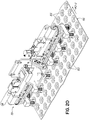
- FIGS. 1-8 illustrate a preferred embodiment of the cup spacing apparatus of the invention. While the term “cup” is used herein, it will be appreciated the invention relate to the handling of containers which, here, are referred to particularly and preferably as “cups” as described, having rims as shown.
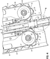
- cups enter the spacing apparatus 10 from the left end and are conveyed by conveyor 11 between two linear stars, comprising conveyors 12, 13 having opposed, elongated operative runs 14, 15 ( FIG. 2 ) operating in a downstream machine direction MD, transporting cups along a cup path having an elongated center line extending between conveyors 12, 13.
- Conveyors 12, 13 each comprise a series of lugs 16 carried on a flexible member or belt 17 backed up by a respective elongated guide 18, 19, respectively.
- the opposed runs 14, 15 are inclined toward one another (tapered respectively inward) at the left-hand entry end of the apparatus 10 to receive the cups as the opposed lugs move both downstream and together.
- Drive sprockets 21, 22 and idler sprockets 23, 24 carry belts 17 and lugs 16 in the machine direction.
- each lug includes a curved pocket defining leading surface 26 and a trailing ramp surface 27, inclined away from a center-line of the cup path toward the pocket surface 26.
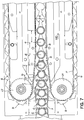
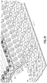
- FIG. 2 illustrates the cups as abutting in a "prime” area just upstream of conveyors 12, 13.
- the cups in "prime” could be pre-spaced.
- a cup C-1 is first engaged by opposed ramp surfaces 27 of a first set of opposed lugs 16. While the cups are continuously conveyed in the direction MD, the velocity of the cups C-1, C-2 is retarded or diminished slightly and the cups C-1, C-2 move relatively down ramp surfaces 27 toward trailing surfaces 31. As the cups and the lugs 16 progress in the downstream direction MD, the cup C-3 is engaged by pocket surfaces 31 of leading lugs 16 with the cup C-4 also engaged by the opposed pocket forming surfaces 26 of a following set of lugs 16. Accordingly, as shown in the FIGS., the linear stars separate the abutting cups from the upstream "prime" area into the pockets 30 at a predetermined pitch.
- cups C-5, C-6 and downstream cups are spaced apart at the desired pitch formed by the lugs 16. Capture of cups C-1 to C-6 is thus continuous, even though the velocity of the cups being engaged by the linear stars may not be constant, while that of the lugs is.
- the cups are "wedged" by the approaching lugs 16 of the respective conveyors 12, 13 as shown in the FIGS. into the spaced pockets 30.
- the cups are preferably held down on their conveyor 11 upstream of the linear stars by a top guide 40, adjusted to accommodate cups with a variety of lids.
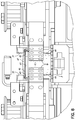
- the cups C have an inwardly-tapering, depending cylindrical wall 44 ( FIG. 8 ) with a wider circular upper mouth 45 defined by a radially extending rim, lip or flange 46, to which is preferably glued a lid 47.
- Rim 46 is captured in slots 48, 49 defined in elongated guides 50, 51. This engagement supports and stabilizes the cups C as they move in the direction MD.
- a dead plate 53 may be used at the end of conveyor 11 as the cups C are then driven by the linear stars.
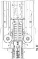
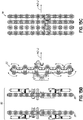
- FIG. 7 Various pitch ch anges in distance between the cups are illustrated in FIG. 7 (here the elongated guides 50, 51 ( FIGS. 3 , 7 ) are removed for clarity).
- the distance a to b represents the starting distance between the cups C when their rims abut.
- the distance b to c represents an initial slight decrease in distance compared to distance a to b as the cups are first engaged by ramps 27.
- the distance c to d represents the cups moving into pockets 30, while distance d to e represents further spacing as the cups move finally into the closing pockets 30 and the distance e to f represents the final spacing pitch between each cup. Accordingly, the spaced distance e to f is greater than the distance a to b.
- the cups could be spaced by a single linear star conveyor on one side of the cups which are slidingly supported by an elongated backup guide on their opposite side, however, the dual opposed linear stars perform well in conjunction.
- linear star is an arbitrary term used by applicant with respect to the spacing apparatus disclosed and whose function is somewhat equivalent to a rotating star wheel used to engage between cylindrical objects and to space them apart.
- the linear stars disclosed herein can be of indefinite length in an elongated space, providing many spaces or “sites” or pockets for cups at predetermined pitch and without a huge size increase in a rotary star to provide an equivalent circumferential distance to hold a larger number of cups, such as 12, at desired pitched distance.
- the lugs 16 of each lug conveyor thus comprise a curved leading surface 26 forming a "backside" of a cup receiving pocket 30.
- a ramp 27 of each lug 16 tapers away or rearwardly from an inward-most end of surface 26 toward a trailing surface 31 of each lug. Trailing surface 31 of each lug forms, together with a curved surface 26 of a following lug, a single cup pocket 30.
- the ramps 27 taper outwardly, with respect to the cup path in which they move, in direction MD from the inward edge of surface 26 outwardly to the inward edge of surface 31.
- Inward-most edge of surface 26 of each lug 16 extends further into the path of cups C than the inward-most edge of surface 31.
- the lugs 16 have an inwardly-directed peak at the juncture of surfaces 26 and ramp 27 and a peak of lesser height at the junction of ramp 27 and surface 31.
- the inward-most extension of ramp 27 with respect to the cup path illustrated in the FIGS. is functional to engage between the cups fed from their abutted "prime” status and to wedge or retard the cups rearwardly (with respect to the direction MD), toward the forming pockets 30 at predetermined pitch.
- the cups are thus "wedged” by the converging ramps of respective lugs 16 of the two lug conveyors, or by the ramp 27 of a lug 16 converging with an opposed guide, into a cup pocket 30 as the lugs move downstream in continuous motion.
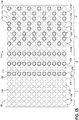
- FIGS. 9-11 a dual lane spacing apparatus 80 is shown wherein abutting cups are introduced to apparatus 80 in two lanes 81, 82 instead of one introductory lane as in FIGS. 1-8 .
- Two conveyors 83, 84 convey the cups toward apparatus 80.
- the conveyors 83, 84 of spacing apparatus 80 comprise respective two linear stars 85, 86, which have opposed runs 87, 88, spaced apart on the outside of respective lanes 81, 82.
- An elongated cup guide 90 is oriented between runs 87, 88 and lanes 81, 82.
- each linear star 85, 86 operates on one respective lane 81, 82 of cups so that each lane of cups is spaced by only one linear star, opposed by guide 90 and a respective guide surface 91, 92 ( FIG. 11 ).
- cup rims 93, 94 are guided in respective elongated slots 95, 96 and 97, 98 formed in elongated guides, as shown, to guide and support cups in adjacent lanes.
- FIG. 11 illustrates one cup C-8 with rim 93 but a sunken lid not bulging upwardly.
- One cup, C-9 has a bulging lid 99 but it too is effectively guided so cups of any lid configuration are reliably handled.
- Lugs 16 individually form cup receiving pockets, opposed by respective guide surfaces 91, 92 to confine and hold the cups at predetermined pitch spacing similarly to the operation of the above embodiment.
- Cups can be picked up simultaneously or selectively for delivery to further downstream orienting and packaging apparatus.
- any suitable sensing system can be used to detect the abutting cups and spaced cups. Any incomplete line or row of spaced cups can be ejected at the end of the linear stars to prevent voids in the staging process and final packaging.
- an overhead three axis picker or end effector is disposed over the stars, descends, picks up the spaced cups (such as 12 of them), lifts them and transports them in a second direction, perpendicularly to the machine direction over a moving tray having a multiplicity of parallel, transverse rows, such as two rows 115, 116 in linked trays 100 of cup-receiving pockets, and such as 12 receptacles in each row.
- FIGS. 12-21 Reference is made to FIGS. 12-21 .
- Preferably spaced cups in a row between the linear stars are further manipulated into patterns with a final pattern, in one embodiment of 12 cups in two layers of six cups each as will be further described.
- One preferred package grouping has a first layer of cups with each adjacent cup inverted with respect to its neighbors. The second layer of cups is reversed such that top up cups are deposited on top down cups so their respective bottoms are engaged and such that bottom up cups are deposited on top up cups so their respective tops or lids engage.
- the 12 cups are thus nested together for packaging in two layers, the carton having minimal interior volume.
- cups in a single line defined by the linear stars are engaged and lifted into respective pockets 103 oriented in parallel rows 115, 116 in a moveable linked tray 100.
- the cups are re-oriented in the tray pockets, as the linked trays 100 are moved or indexed along, by a plurality of pickers or end effectors as will be described.
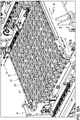
- FIG. 13 shows the orientation of the cups in the moving tray.
- FIG. 13 shows the cup position and orientation diagrammatically, while FIGS. 12 , 12A and 17-21 show photographically the overall re-orienting system.
- a tray conveyor is preferably comprised of a series of trays 100 hinged together so the trays 100 operate as a conveyor with an upper run moving in the direction of MD-2.
- Each individual tray link defines one or more, and preferably two, transverse rows 115, 116 of cup receiving pockets 103 which, in FIG. 13 , are each filled with a cup.
- cups such as at C-8 are initially oriented top up. Cups such as at C-9 are illustrated downstream with their bottoms up and top rim 102 down, as further discussed.
- FIG. 13 illustrates essentially the entire upper run of the trays 100 from loading to a downstream unload position such as represente in FIG. 21 .
- cups such as at C-8 and C-9 are illustrated in the tray 100 to demonstrate the cup orientation as the tray 100 moves through various orientation stages from uniform disposition in the rows of Stage A to re-oriented positions in stages C and D.
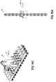
- FIGS. 22 Illustrated in the FIGS. are the pickers or end effectors 110-113 for re-orienting the cups in trays 100, and effector 114 for transporting selected cups to a two-lane transfer or loading conveyor 120 (FIG. 22) where the re-oriented cups are gathered into respective layers for grouping and cartoning.
- Picker 110 functions to transfer a row of cups, top up, to a row of pockets 103 in a tray 100.
- Picker 112 functions to invert cups in alternating rows in a tray 100.
- Picker 113 functions to rotate cups in the same position in two adjacent rows, and picker 114 serves to lift 4 cups each from an adjacent row and deposit them on a transfer conveyor for further group forming.
- Picker 110 is thus operationally correlated with Stage A, picker 112 with Stage B, picker 113 with Stage C, and picker 114 with Stage D.
- Pickers 110-114 may comprise any useful end effector or apparatus for gripping or holding cups and moving them as will be described.
- Picker 110 moves in a machine direction MD, lowers to engage a row of spaced cups in or between the linear stars while moving, lifts the row of engaged cups and moves in the direction MD-2 to deposit the rows of cups into pockets 103 in tray rows 115, 116 of a tray 100.
- Trays 100 move in direction MD-2 to transport successive rows of cups beneath picker 112 which is comprised of two gripper racks 117, 118.
- Rack 117 engages the top-up cups in an alternating tray row and rotates about a transverse axis so the cups are horizontally-oriented, while rack 118 rotates in an opposite direction to grip the bottoms of cups held horizontally by rack 117.
- Rack 118 then reverses in rotation and places the cups top down in the same row pockets from which rack 117 removed them (with the tray 100 having been indexed in direction MD-2).
- FIG. 19 The cooperating position of racks 117, 118 wherein cups are transferred from rack 117 to rack 118 is illustrated in FIG. 19 .
- cups in every other tray row are inverted, top down as shown in Stage B, FIG. 13 .
- indexing of tray 100 in direction MD-2 brings the alternately inverted rows of cups in Stage B to position for further orientation by picker 113.
- Shiftable picker 113 has a plurality of six picker heads mounted for 180 degree rotation about vertical axes as illustrated in FIG. 15 .
- Picker 113 descends down upon every other two longitudinal rows of cups in Stage B, grips the cups in adjacent rows and rotates 180 degrees, now reversing the cups at the same position In the two adjacent rows to achieve the orientation of cups to that of Stage C ( FIG. 13 ).
- the six heads of picker 113 operate only on every other cup position in each adjacent row, such that the cup orientation of Stage C is generated.
- the trays 100 are indexed between shifting of the picker 113 so the cup configuration is as shown in FIG. 13 .
- tray 100 carries the cups, now in Stage C, and as shown, beneath picker 114 which picks up cups in the four rows shown and transports them to a loading conveyor 120 ( FIG. 21 ) for movement to a robot station (not shown) where the rows of cups are collapsed and the outside two rows are lifted up and placed on top of row 123, 124, forming a cup group of two layers for packaging.
- Cups C-8 reside in adjacent rows 116 in Stage A. Cups in each other row, such as a row 125 and a row 126 are inverted by picker 112 so the cups C-9 in alternate adjacent rows 125, 126 for example, are inverted to the position shown in FIG. 13 , with cups in one transverse row having tops up and in alternate adjacent rows having tops down.
- FIG. 13 illustrates the staging system for the whole length of tray 100, however, it may be illustrative to follow the progress of a single cup as it is moved and re-oriented in the direction MD-2.
- a virtual cup C-20 is originally oriented top up in tray 100. Located in an alternate row, cup C-20 is inverted in Stage B. Thereafter, a cup C-20 in every other set of two rows is rotated to change places with the virtual cup C-20a. Cups in the downstream set of two rows 129, 130 are not so re-oriented. The result is the pattern of cups in the four rows 131-134 of Stage D ( FIG. 13 ) for transport by picker 114 onto loading conveyor 120.
- the cups on an upper layer preferably engage the cups on the lower layer top-to-top or bottom-to-bottom respectively, as disclosed.
- the loading conveyor 120 of this embodiment includes trays (which may be articulated) of an endless conveyor having four lanes of pockets 140-143 for cups in the pattern shown.
- Loading conveyor 120 transports the tray with the cups to a load building station, preferably including one, two or more robots (not shown).
- the apparatus can be modified to produce a wide variety of packaging configurations, including changes in the length or orientation of the rows or lanes, changes in the cup orientation within the tray or conveyor pockets, changes in the final group or package build and the like. Carton or package builds of various counts can be attained such as 6, 10, 12, as described, 18, etc.
- the invention comprises a container pitch forming apparatus wherein containers such as cups are arranged in a spaced-apart pattern at predetermined pitch, from an abutted "prime" condition where the cups (cup rims) are abutted.
- FIGS. 2-4 and 6-7 illustrate the cups in an abutted prime condition.
- FIG. 10 illustrate first a single cup path formed by opposed lug conveyors 12, 13 ( FIG. 2 ) and, second, a dual lane cup conveyor where an elongated, smooth guide 90 is disposed between two lug conveyors 85, 86 ( FIG. 10 ), also contemplated are a single cup path defined on one side by a guide such as guide 90, and a single lug conveyor on the other side where the lugs include a surface defining a cup receiving pocket and a ramp inclined toward that surface.
- the upstream end of any cup lane herein includes either a lug conveyor with the entry end tapered toward an opposed lug conveyor or guide, or a guide tapered toward a lug conveyor for receiving and feeding cups.
- the respective conveyors or guides thus define a wedge in which approaching lugs of respective lug conveyors or a lug conveyor and guide function to space and locate cups in the receiving pockets of lugs.
- a different plurality of pickers, conveyors and robots can be used. Dual packaging/build groups can be provided.
- Cups are positively controlled throughout the system, pitched by the linear stars.
- the orienting or staging system can be used to handle spaced cups, however generated, and at the downstream end of the linear stars, the lugs of one conveyor move away from the lugs of an opposed conveyor or guide to facilitate any needed clean-out.
- Cups are thus controlled, transported and formed for packing in one or more patterns as desired.
Landscapes
- Engineering & Computer Science (AREA)
- Mechanical Engineering (AREA)
- Supplying Of Containers To The Packaging Station (AREA)
Claims (12)
- Vorrichtung zum Beabstanden von Containern auf eine vorbestimmte Teilung, umfassend wenigstens einen Ansatzförderer (12, 13, 83, 84), der auf einer Seite eines länglichen Containerverlaufs (14, 15) definiert ist, und umfassend eine Mehrzahl von seriell beförderten Ansätzen (16), dadurch gekennzeichnet, dass jeder Ansatz (16) eine gekrümmte vordere Fläche (26) und eine hintere Fläche (31) jeweils zum teilweisen Definieren einer Containeraufnahmetasche (30) sowie einer Rampe (27) zwischen der gekrümmten vorderen Fläche (26) und der hinteren Fläche (31) umfasst, wobei sich die Rampe (27) von einem innersten Ende der gekrümmten vorderen Fläche (26) in Richtung der hinteren Fläche (31) weg oder nach hinten verjüngt, und dadurch, dass benachbarte der genannten Ansätze (16) zusammen eine Containeraufnahmetasche (30) einschließlich der gekrümmten vorderen Fläche (26) eines hinteren Ansatzes und der hinteren Fläche (31) des vorangehenden Ansatzes definieren, wobei die Rampe (27) in Richtung der hinteren Fläche (31) geneigt ist, um in einen Container einzugreifen und ihn in die genannte Tasche (30) zu leiten.
- Vorrichtung nach Anspruch 1, die ferner eine längliche Führung (40, 50, 51, 90) umfasst, die von dem genannten einen Ansatzförderer (12, 13) beabstandet ist und in dieselbe Richtung wie dieser verläuft, wobei die genannte Führung eine andere Seite des genannten länglichen Containerverlaufs definiert.
- Vorrichtung nach Anspruch 1 mit einem Paar Ansatzförderer (12, 13) jeweils mit einem longitudinalen Verlauf und jeweils mit Ansätzen (16) gegenüber Ansätzen des anderen Förderers.
- Vorrichtung nach Anspruch 3 mit einem Paar gegenüberliegenden Containerführungen (50, 51), wobei jede Führung (50, 51) einen Containerrandführungsschlitz (48, 49) zum Aufnehmen und Leiten von Containerrändern definiert.
- Vorrichtung nach Anspruch 3, wobei die genannten Förderer (12, 13) kontinuierlich beweglich sind, um Container kontinuierlich dazwischen zu transportieren.
- Vorrichtung nach Anspruch 1 mit einem ersten und einem zweiten Ansatzförderer (83, 84), jeweils mit einem longitudinalen Verlauf von Ansätzen (16), wobei die genannten Verläufe einander zugewandt sind, und einer zwischen den genannten Verläufen angeordneten länglichen Führung (90), wobei eine Containerspur zwischen jedem der genannten Verläufe und der genannten Führung (90) definiert wird und wobei die Containeraufnahmetaschen (30) zwischen benachbarten Ansätzen (16) und der genannten Führung (90) definiert sind.
- Vorrichtung nach Anspruch 6 mit einem Paar gegenüberliegenden Containerführungen (50, 51), wobei jede Führung (50, 51) teilweise einen Randführungsschlitz (48, 49) zum Aufnehmen und Leiten von Containerrändern definiert.
- Vorrichtung nach Anspruch 6, wobei die genannte längliche Führung (90) zwischen den genannten Verläufen längliche Containerpfade auf jeder Seite der genannten Führung (90) definiert.
- Vorrichtung nach Anspruch 8, wobei jeder der genannten ersten und zweiten Ansatzförderer (83, 84) einen Abschnitt aufweist, der sich jeweils einwärts in Richtung der genannten länglichen Führung (90) verjüngt.
- Vorrichtung nach Anspruch 9, wobei die genannten Förderer (83, 84) kontinuierlich beweglich sind, um Container kontinuierlich zu transportieren.
- Verfahren zum Beabstanden von aneinander angrenzenden Bechern zu einer vorbestimmten nicht aneinander angrenzenden Teilung, das die folgenden Schritte beinhaltet: Transportieren von Bechern seriell zu einem Pfad, der durch wenigstens eine Mehrzahl von seriell beförderten Ansätzen (16) von einem Förderer (12, 13, 83, 84) definiert wird, angeordnet in einem länglichen Fördererverlauf (14, 15), wobei jeder Ansatz (16) eine gekrümmte vordere Fläche (26) und eine hintere Fläche (31) jeweils zum teilweisen Definieren einer Containeraufnahmetasche (30) und einer Rampe (27) hat, wobei sich die Rampe (27) jedes Ansatzes zwischen der gekrümmten vorderen Fläche (26) und der hinteren Fläche (31) des Ansatzes befindet und wobei sich die Rampe (27) von einem innersten Ende der gekrümmten vorderen Fläche (26) in Richtung der hinteren Fläche (31) weg oder nach hinten verjüngt, wobei benachbarte der genannten Ansätze (16) zusammen eine Containeraufnahmetasche (30) mit der gekrümmten vorderen Fläche (26) eines hinteren Ansatzes und der hinteren Fläche (31) des vorangehenden Ansatzes definieren, wobei die Rampe (27) in Richtung der hinteren Fläche (31) zum Eingreifen in einen Container und Leiten desselben in die genannte Tasche (30) geneigt ist; Eingreifen in Becher seriell mit den Rampen (27) von jeweiligen Eingriffsansätzen (16); Verlangsamen von im Eingriff befindlichen Bechern; und Bewegen von im Eingriff befindlichen Bechern in die durch die genannten jeweiligen Eingriffsansätze (16) definierten Taschen (30).
- Verfahren nach Anspruch 11, das den Schritt des Führens der genannten Becher an Führungsrändern der genannten Becher in länglichen Schlitzen beinhaltet.
Applications Claiming Priority (3)
| Application Number | Priority Date | Filing Date | Title |
|---|---|---|---|
| US201161628753P | 2011-11-04 | 2011-11-04 | |
| US13/667,528 US9272849B2 (en) | 2011-11-04 | 2012-11-02 | Cup feeder |
| PCT/US2012/063550 WO2013101341A1 (en) | 2011-11-04 | 2012-11-05 | Cup feeder |
Publications (2)
| Publication Number | Publication Date |
|---|---|
| EP2773564A1 EP2773564A1 (de) | 2014-09-10 |
| EP2773564B1 true EP2773564B1 (de) | 2018-12-19 |
Family
ID=48223795
Family Applications (1)
| Application Number | Title | Priority Date | Filing Date |
|---|---|---|---|
| EP12788030.0A Not-in-force EP2773564B1 (de) | 2011-11-04 | 2012-11-05 | Becherzuführer |
Country Status (5)
| Country | Link |
|---|---|
| US (3) | US9272849B2 (de) |
| EP (1) | EP2773564B1 (de) |
| CA (2) | CA2854474C (de) |
| ES (1) | ES2707577T3 (de) |
| WO (1) | WO2013101341A1 (de) |
Families Citing this family (34)
| Publication number | Priority date | Publication date | Assignee | Title |
|---|---|---|---|---|
| ITBO20130643A1 (it) * | 2013-11-25 | 2015-05-26 | Gima Spa | Stazione di prelievo e consegna di prodotti |
| WO2016038634A1 (en) * | 2014-09-10 | 2016-03-17 | Bonino S.P.A. Con Unico Azionista | Object orienting system |
| CN105800267B (zh) * | 2015-06-08 | 2018-07-03 | 扬州美达灌装机械有限公司 | 一种盖下灌装机进罐机构 |
| EP3106397B1 (de) * | 2015-06-15 | 2018-03-14 | Tetra Laval Holdings & Finance SA | Verpackungsgruppierungseinheit mit reduzierung der linearen verpackungsgeschwindigkeit |
| NL2015348B1 (en) * | 2015-08-25 | 2017-03-16 | Fuji Seal Int Inc | System and method of discharging a tubular storage assembly |
| US11001400B2 (en) * | 2016-01-20 | 2021-05-11 | R.A Jones & Co. | Apparatus and methods for transferring continuously moving articles to continuously moving packages with intervening article grouping and group pitch adjustment |
| CN105692046B (zh) * | 2016-03-02 | 2018-02-27 | 安徽省亮亮纺织有限公司 | 一种布匹高低位运送设备 |
| NL2016517B1 (en) * | 2016-03-31 | 2017-10-17 | Fuji Seal Int Inc | Apparatus and method for discharging spouted containers |
| US10471598B1 (en) * | 2016-06-10 | 2019-11-12 | Eric Fragola | Robotic platform |
| WO2018081079A1 (en) * | 2016-10-26 | 2018-05-03 | Sealed Air Corporation (Us) | Discharge conveyor system for cut cushioning material |
| JP6970500B2 (ja) * | 2016-12-14 | 2021-11-24 | 日清食品ホールディングス株式会社 | カップ状容器搬送装置 |
| IT201700047487A1 (it) * | 2017-05-03 | 2018-11-03 | Cavanna S P A Con Socio Unico | Apparato per il confezionamento ordinato di prodotti in elementi contenitori e relativo metodo |
| CN107235319A (zh) * | 2017-06-22 | 2017-10-10 | 苏州长光华医生物医学工程有限公司 | 一种全自动理杯上料机构 |
| CN108674727A (zh) * | 2018-03-16 | 2018-10-19 | 合肥普发谐利信息科技有限公司 | 一种新型玻璃瓶打包装置 |
| EP3774553B1 (de) * | 2018-04-04 | 2022-01-19 | I.M.A. Industria Macchine Automatiche S.p.A. | Einheit und verfahren zum überführen von einwegbehältern |
| US11918032B2 (en) | 2018-04-26 | 2024-03-05 | Mpi, Llc | Packer station of a packaging apparatus and system |
| US11148835B2 (en) | 2018-04-26 | 2021-10-19 | Mpi, Llc | Packaging apparatus and system |
| CN108529538B (zh) * | 2018-05-10 | 2020-06-02 | 南通市赛博制药设备科技有限公司 | 一种医学制药用固定输送机械 |
| US11371494B2 (en) * | 2018-10-02 | 2022-06-28 | Gas Technology Institute | Solid particulate pump |
| IT201900008835A1 (it) * | 2019-06-13 | 2020-12-13 | Regina Catene Calibrate Spa | Tampone gommato, in particolare per catene per linee di movimentazione/sollevamento di prodotti. |
| CN111170020A (zh) * | 2020-01-07 | 2020-05-19 | 烟台东泽电气科技股份有限公司 | 一种等间距分料结构 |
| CN111216986B (zh) * | 2020-02-29 | 2021-04-06 | 南京溧水高新创业投资管理有限公司 | 料架 |
| CN111689451B (zh) * | 2020-05-22 | 2022-02-01 | 开封合成时代润滑科技有限公司 | 一种润滑油灌装自动封盖装置 |
| IT202000016648A1 (it) * | 2020-07-09 | 2022-01-09 | Gd Spa | Dispositivo di trasferimento, particolarmente per una macchina confezionatrice |
| IT202000016675A1 (it) | 2020-07-09 | 2022-01-09 | Gd Spa | Dispositivo e procedimento di alimentazione di articoli da confezionare |
| IT202000016654A1 (it) * | 2020-07-09 | 2022-01-09 | Gd Spa | Dispositivo e procedimento di confezionamento di articoli da confezionare |
| CN111874335B (zh) * | 2020-07-22 | 2022-04-01 | 南宁维纽科技有限公司 | 一种饮用桶装水盖的整备设备及整备工艺 |
| EP3950543B1 (de) * | 2020-08-04 | 2025-10-01 | Illinois Tool Works INC. | Fördervorrichtung für eine verpackungsmaschine, transportvorrichtung zum transportieren von produkten sowie verpackungsmaschine |
| TWI781715B (zh) * | 2020-08-07 | 2022-10-21 | 日商雷恩自動機股份有限公司 | 食品材料的計量供給裝置 |
| US11794438B2 (en) | 2020-12-07 | 2023-10-24 | Mark W. Holderman | Packaging apparatus, system, and method for forming filled cones |
| US12004557B2 (en) | 2020-12-07 | 2024-06-11 | Mpi, Llc | Packaging apparatus, system, and method for forming filled cones |
| JP7751882B2 (ja) * | 2022-07-04 | 2025-10-09 | アイカム株式会社 | 皿移送装置 |
| DE102022134497A1 (de) * | 2022-12-22 | 2024-06-27 | Khs Gmbh | Transportvorrichtung zum Transportieren von Verpackungen |
| WO2025100331A1 (ja) * | 2023-11-06 | 2025-05-15 | パナソニックホールディングス株式会社 | ロボットハンド、およびロボットシステム |
Citations (1)
| Publication number | Priority date | Publication date | Assignee | Title |
|---|---|---|---|---|
| EP2586714A1 (de) * | 2011-10-31 | 2013-05-01 | Tetra Laval Holdings & Finance S.A. | Förderband für eine Artikelbehandlungseinheit, insbesondere für eine Falteinheit zur Herstellung von Verpackungen für gießbare Lebensmittelprodukte |
Family Cites Families (22)
| Publication number | Priority date | Publication date | Assignee | Title |
|---|---|---|---|---|
| US3108682A (en) | 1961-02-16 | 1963-10-29 | Continental Can Co | Glass jar grippers |
| US3253694A (en) * | 1964-07-07 | 1966-05-31 | American Can Co | Apparatus for collating tapered articles |
| DE1963111A1 (de) | 1969-12-17 | 1970-11-19 | Ganzhorn & Stirn | Verfahren und Vorrichtung zur Gefaessuebergabe von einem gleichfoermig laufenden Transporteur auf ein Fliessband |
| US4002005A (en) * | 1973-06-19 | 1977-01-11 | Owens-Illinois, Inc. | Package of nested containers and method and apparatus for producing same |
| US4067433A (en) * | 1975-12-05 | 1978-01-10 | Profile Associates Incorporated | Packaging machinery |
| US4064987A (en) * | 1976-02-12 | 1977-12-27 | Rowan Daniel J | Conveyor system for handling non-rigid containers |
| US4095390A (en) * | 1976-04-01 | 1978-06-20 | Mckenna Equipment Company, Inc. | Machine and process for capping and sealing containers |
| US4227606A (en) | 1979-02-27 | 1980-10-14 | Bogatzki Hans Ulrich | Apparatus for spacing articles moving in a line |
| US4800704A (en) * | 1987-12-14 | 1989-01-31 | Toru Ishii | Apparatus for aligning and packing fruits or vegetables into packages |
| US5250008A (en) * | 1989-07-08 | 1993-10-05 | Wafios Maschinenfabrik Gmbh & Co. | Apparatus for making and conveying elongated headed wire workpieces |
| US5267590A (en) * | 1990-10-11 | 1993-12-07 | R & D Innovators, Inc. | Container filler, especially for ballast having contoured sweep for arraying containers |
| US5353908A (en) * | 1992-02-12 | 1994-10-11 | Shibuya Kogyo Company, Ltd. | Suspended conveyance apparatus |
| CA2195589A1 (en) * | 1996-10-18 | 1998-04-19 | Walter C. Egger | Conveyor assembly for the conveying of open containers |
| US6360873B1 (en) * | 1997-09-19 | 2002-03-26 | The Mead Corporation | Article grouping mechanism |
| ITBO20010093A1 (it) | 2001-02-20 | 2002-08-20 | Vittorio Vicini | Dispositivo per la messa a passo di contenitori, in particolare di bottiglie |
| CA2426057C (en) * | 2002-04-22 | 2018-03-06 | Milos Misha Subotincic | End effector with multiple pick-up members |
| DE10360160A1 (de) * | 2003-12-20 | 2005-07-21 | Kuka Innotec Gmbh | Verfahren und Vorrichtung zum Handhaben stabförmiger Objekte |
| US7803232B2 (en) * | 2005-11-17 | 2010-09-28 | Mcbrady Engineering, Inc. | Multi-pass inverting bottle cleaner |
| US8588960B1 (en) * | 2012-06-25 | 2013-11-19 | Uhlmann Packaging Systems, L.P. | Pick-and place package marshalling system |
| US9073222B2 (en) * | 2013-11-14 | 2015-07-07 | Propack Processing and Packaging Systems, Inc. | End effector |
| ITBO20130642A1 (it) * | 2013-11-25 | 2015-05-26 | Gima Spa | Gruppo di trasporto ed allineamento ordinato di prodotti |
| US9783372B2 (en) * | 2015-01-28 | 2017-10-10 | Kla-Tencor Corporation | Flipping apparatus, system and method for processing articles |
-
2012
- 2012-11-02 US US13/667,528 patent/US9272849B2/en active Active
- 2012-11-05 CA CA2854474A patent/CA2854474C/en active Active
- 2012-11-05 ES ES12788030T patent/ES2707577T3/es active Active
- 2012-11-05 EP EP12788030.0A patent/EP2773564B1/de not_active Not-in-force
- 2012-11-05 CA CA3080082A patent/CA3080082C/en active Active
- 2012-11-05 WO PCT/US2012/063550 patent/WO2013101341A1/en not_active Ceased
-
2016
- 2016-01-25 US US15/005,154 patent/US9776751B2/en active Active
-
2017
- 2017-08-29 US US15/689,089 patent/US9950822B2/en active Active
Patent Citations (1)
| Publication number | Priority date | Publication date | Assignee | Title |
|---|---|---|---|---|
| EP2586714A1 (de) * | 2011-10-31 | 2013-05-01 | Tetra Laval Holdings & Finance S.A. | Förderband für eine Artikelbehandlungseinheit, insbesondere für eine Falteinheit zur Herstellung von Verpackungen für gießbare Lebensmittelprodukte |
Also Published As
| Publication number | Publication date |
|---|---|
| CA2854474A1 (en) | 2013-07-04 |
| US20170355478A1 (en) | 2017-12-14 |
| US9272849B2 (en) | 2016-03-01 |
| US20130115033A1 (en) | 2013-05-09 |
| US20160137327A1 (en) | 2016-05-19 |
| CA3080082A1 (en) | 2013-07-04 |
| WO2013101341A1 (en) | 2013-07-04 |
| EP2773564A1 (de) | 2014-09-10 |
| CA2854474C (en) | 2020-07-07 |
| CA3080082C (en) | 2022-04-12 |
| US9776751B2 (en) | 2017-10-03 |
| US9950822B2 (en) | 2018-04-24 |
| ES2707577T3 (es) | 2019-04-04 |
Similar Documents
| Publication | Publication Date | Title |
|---|---|---|
| EP2773564B1 (de) | Becherzuführer | |
| US11242211B2 (en) | Bin packing system and method | |
| CN102811910B (zh) | 用于外包装物品以形成物品堆和包括多个物品和纸板外包装类型的方法和机器 | |
| US11383865B2 (en) | Food conveyor and packaging systems and methods | |
| EP1183200B1 (de) | Verfahren und vorrichtung zum stapeln von tortillachips | |
| CN110431095A (zh) | 用于分层堆垛的产品批次的生产 | |
| US7540369B2 (en) | Product handling system | |
| CN115867489A (zh) | 包装方法、包装设备及相关的控制系统 | |
| US20190023441A1 (en) | Method and device for handling bag chains | |
| WO1999006281A1 (en) | Product-transferring apparatus and assembly comprising such product-transferring apparatus | |
| US20170066606A1 (en) | System for placing elements in an orderly fashion | |
| US3531912A (en) | Assortment assembling apparatus | |
| WO2025037984A1 (en) | Method and system for transferring egg trays | |
| US12319520B2 (en) | Singling unit for articles stacked in a nested configuration | |
| EP1383698B1 (de) | Verfahren und vorrichtung zur bildung von regelmässigen stapeln von ungleichen, im wesentlichen flächigen, gegenständen | |
| US20250289145A1 (en) | Gripper for a handling device | |
| JP2024128242A (ja) | 整列装置 | |
| JP2001220017A (ja) | 取り外し装置及び取り外し方法 |
Legal Events
| Date | Code | Title | Description |
|---|---|---|---|
| PUAI | Public reference made under article 153(3) epc to a published international application that has entered the european phase |
Free format text: ORIGINAL CODE: 0009012 |
|
| 17P | Request for examination filed |
Effective date: 20140521 |
|
| AK | Designated contracting states |
Kind code of ref document: A1 Designated state(s): AL AT BE BG CH CY CZ DE DK EE ES FI FR GB GR HR HU IE IS IT LI LT LU LV MC MK MT NL NO PL PT RO RS SE SI SK SM TR |
|
| DAX | Request for extension of the european patent (deleted) | ||
| 17Q | First examination report despatched |
Effective date: 20150821 |
|
| STAA | Information on the status of an ep patent application or granted ep patent |
Free format text: STATUS: EXAMINATION IS IN PROGRESS |
|
| GRAP | Despatch of communication of intention to grant a patent |
Free format text: ORIGINAL CODE: EPIDOSNIGR1 |
|
| STAA | Information on the status of an ep patent application or granted ep patent |
Free format text: STATUS: GRANT OF PATENT IS INTENDED |
|
| INTG | Intention to grant announced |
Effective date: 20180705 |
|
| GRAS | Grant fee paid |
Free format text: ORIGINAL CODE: EPIDOSNIGR3 |
|
| GRAA | (expected) grant |
Free format text: ORIGINAL CODE: 0009210 |
|
| STAA | Information on the status of an ep patent application or granted ep patent |
Free format text: STATUS: THE PATENT HAS BEEN GRANTED |
|
| AK | Designated contracting states |
Kind code of ref document: B1 Designated state(s): AL AT BE BG CH CY CZ DE DK EE ES FI FR GB GR HR HU IE IS IT LI LT LU LV MC MK MT NL NO PL PT RO RS SE SI SK SM TR |
|
| REG | Reference to a national code |
Ref country code: GB Ref legal event code: FG4D |
|
| REG | Reference to a national code |
Ref country code: CH Ref legal event code: EP |
|
| REG | Reference to a national code |
Ref country code: IE Ref legal event code: FG4D |
|
| REG | Reference to a national code |
Ref country code: DE Ref legal event code: R096 Ref document number: 602012054912 Country of ref document: DE |
|
| REG | Reference to a national code |
Ref country code: AT Ref legal event code: REF Ref document number: 1078424 Country of ref document: AT Kind code of ref document: T Effective date: 20190115 |
|
| REG | Reference to a national code |
Ref country code: ES Ref legal event code: FG2A Ref document number: 2707577 Country of ref document: ES Kind code of ref document: T3 Effective date: 20190404 |
|
| REG | Reference to a national code |
Ref country code: NL Ref legal event code: MP Effective date: 20181219 |
|
| PG25 | Lapsed in a contracting state [announced via postgrant information from national office to epo] |
Ref country code: HR Free format text: LAPSE BECAUSE OF FAILURE TO SUBMIT A TRANSLATION OF THE DESCRIPTION OR TO PAY THE FEE WITHIN THE PRESCRIBED TIME-LIMIT Effective date: 20181219 Ref country code: LV Free format text: LAPSE BECAUSE OF FAILURE TO SUBMIT A TRANSLATION OF THE DESCRIPTION OR TO PAY THE FEE WITHIN THE PRESCRIBED TIME-LIMIT Effective date: 20181219 Ref country code: NO Free format text: LAPSE BECAUSE OF FAILURE TO SUBMIT A TRANSLATION OF THE DESCRIPTION OR TO PAY THE FEE WITHIN THE PRESCRIBED TIME-LIMIT Effective date: 20190319 Ref country code: FI Free format text: LAPSE BECAUSE OF FAILURE TO SUBMIT A TRANSLATION OF THE DESCRIPTION OR TO PAY THE FEE WITHIN THE PRESCRIBED TIME-LIMIT Effective date: 20181219 Ref country code: BG Free format text: LAPSE BECAUSE OF FAILURE TO SUBMIT A TRANSLATION OF THE DESCRIPTION OR TO PAY THE FEE WITHIN THE PRESCRIBED TIME-LIMIT Effective date: 20190319 Ref country code: LT Free format text: LAPSE BECAUSE OF FAILURE TO SUBMIT A TRANSLATION OF THE DESCRIPTION OR TO PAY THE FEE WITHIN THE PRESCRIBED TIME-LIMIT Effective date: 20181219 |
|
| REG | Reference to a national code |
Ref country code: LT Ref legal event code: MG4D |
|
| REG | Reference to a national code |
Ref country code: AT Ref legal event code: MK05 Ref document number: 1078424 Country of ref document: AT Kind code of ref document: T Effective date: 20181219 |
|
| PG25 | Lapsed in a contracting state [announced via postgrant information from national office to epo] |
Ref country code: AL Free format text: LAPSE BECAUSE OF FAILURE TO SUBMIT A TRANSLATION OF THE DESCRIPTION OR TO PAY THE FEE WITHIN THE PRESCRIBED TIME-LIMIT Effective date: 20181219 Ref country code: GR Free format text: LAPSE BECAUSE OF FAILURE TO SUBMIT A TRANSLATION OF THE DESCRIPTION OR TO PAY THE FEE WITHIN THE PRESCRIBED TIME-LIMIT Effective date: 20190320 Ref country code: RS Free format text: LAPSE BECAUSE OF FAILURE TO SUBMIT A TRANSLATION OF THE DESCRIPTION OR TO PAY THE FEE WITHIN THE PRESCRIBED TIME-LIMIT Effective date: 20181219 Ref country code: SE Free format text: LAPSE BECAUSE OF FAILURE TO SUBMIT A TRANSLATION OF THE DESCRIPTION OR TO PAY THE FEE WITHIN THE PRESCRIBED TIME-LIMIT Effective date: 20181219 |
|
| PG25 | Lapsed in a contracting state [announced via postgrant information from national office to epo] |
Ref country code: NL Free format text: LAPSE BECAUSE OF FAILURE TO SUBMIT A TRANSLATION OF THE DESCRIPTION OR TO PAY THE FEE WITHIN THE PRESCRIBED TIME-LIMIT Effective date: 20181219 |
|
| PG25 | Lapsed in a contracting state [announced via postgrant information from national office to epo] |
Ref country code: PL Free format text: LAPSE BECAUSE OF FAILURE TO SUBMIT A TRANSLATION OF THE DESCRIPTION OR TO PAY THE FEE WITHIN THE PRESCRIBED TIME-LIMIT Effective date: 20181219 Ref country code: CZ Free format text: LAPSE BECAUSE OF FAILURE TO SUBMIT A TRANSLATION OF THE DESCRIPTION OR TO PAY THE FEE WITHIN THE PRESCRIBED TIME-LIMIT Effective date: 20181219 Ref country code: PT Free format text: LAPSE BECAUSE OF FAILURE TO SUBMIT A TRANSLATION OF THE DESCRIPTION OR TO PAY THE FEE WITHIN THE PRESCRIBED TIME-LIMIT Effective date: 20190419 |
|
| PG25 | Lapsed in a contracting state [announced via postgrant information from national office to epo] |
Ref country code: SK Free format text: LAPSE BECAUSE OF FAILURE TO SUBMIT A TRANSLATION OF THE DESCRIPTION OR TO PAY THE FEE WITHIN THE PRESCRIBED TIME-LIMIT Effective date: 20181219 Ref country code: EE Free format text: LAPSE BECAUSE OF FAILURE TO SUBMIT A TRANSLATION OF THE DESCRIPTION OR TO PAY THE FEE WITHIN THE PRESCRIBED TIME-LIMIT Effective date: 20181219 Ref country code: SM Free format text: LAPSE BECAUSE OF FAILURE TO SUBMIT A TRANSLATION OF THE DESCRIPTION OR TO PAY THE FEE WITHIN THE PRESCRIBED TIME-LIMIT Effective date: 20181219 Ref country code: RO Free format text: LAPSE BECAUSE OF FAILURE TO SUBMIT A TRANSLATION OF THE DESCRIPTION OR TO PAY THE FEE WITHIN THE PRESCRIBED TIME-LIMIT Effective date: 20181219 Ref country code: IS Free format text: LAPSE BECAUSE OF FAILURE TO SUBMIT A TRANSLATION OF THE DESCRIPTION OR TO PAY THE FEE WITHIN THE PRESCRIBED TIME-LIMIT Effective date: 20190419 |
|
| REG | Reference to a national code |
Ref country code: DE Ref legal event code: R097 Ref document number: 602012054912 Country of ref document: DE |
|
| PLBE | No opposition filed within time limit |
Free format text: ORIGINAL CODE: 0009261 |
|
| STAA | Information on the status of an ep patent application or granted ep patent |
Free format text: STATUS: NO OPPOSITION FILED WITHIN TIME LIMIT |
|
| PG25 | Lapsed in a contracting state [announced via postgrant information from national office to epo] |
Ref country code: DK Free format text: LAPSE BECAUSE OF FAILURE TO SUBMIT A TRANSLATION OF THE DESCRIPTION OR TO PAY THE FEE WITHIN THE PRESCRIBED TIME-LIMIT Effective date: 20181219 Ref country code: AT Free format text: LAPSE BECAUSE OF FAILURE TO SUBMIT A TRANSLATION OF THE DESCRIPTION OR TO PAY THE FEE WITHIN THE PRESCRIBED TIME-LIMIT Effective date: 20181219 |
|
| 26N | No opposition filed |
Effective date: 20190920 |
|
| PG25 | Lapsed in a contracting state [announced via postgrant information from national office to epo] |
Ref country code: SI Free format text: LAPSE BECAUSE OF FAILURE TO SUBMIT A TRANSLATION OF THE DESCRIPTION OR TO PAY THE FEE WITHIN THE PRESCRIBED TIME-LIMIT Effective date: 20181219 |
|
| PG25 | Lapsed in a contracting state [announced via postgrant information from national office to epo] |
Ref country code: TR Free format text: LAPSE BECAUSE OF FAILURE TO SUBMIT A TRANSLATION OF THE DESCRIPTION OR TO PAY THE FEE WITHIN THE PRESCRIBED TIME-LIMIT Effective date: 20181219 |
|
| REG | Reference to a national code |
Ref country code: CH Ref legal event code: PL |
|
| PG25 | Lapsed in a contracting state [announced via postgrant information from national office to epo] |
Ref country code: CH Free format text: LAPSE BECAUSE OF NON-PAYMENT OF DUE FEES Effective date: 20191130 Ref country code: MC Free format text: LAPSE BECAUSE OF FAILURE TO SUBMIT A TRANSLATION OF THE DESCRIPTION OR TO PAY THE FEE WITHIN THE PRESCRIBED TIME-LIMIT Effective date: 20181219 Ref country code: LU Free format text: LAPSE BECAUSE OF NON-PAYMENT OF DUE FEES Effective date: 20191105 Ref country code: LI Free format text: LAPSE BECAUSE OF NON-PAYMENT OF DUE FEES Effective date: 20191130 |
|
| REG | Reference to a national code |
Ref country code: BE Ref legal event code: MM Effective date: 20191130 |
|
| PG25 | Lapsed in a contracting state [announced via postgrant information from national office to epo] |
Ref country code: IE Free format text: LAPSE BECAUSE OF NON-PAYMENT OF DUE FEES Effective date: 20191105 |
|
| PG25 | Lapsed in a contracting state [announced via postgrant information from national office to epo] |
Ref country code: BE Free format text: LAPSE BECAUSE OF NON-PAYMENT OF DUE FEES Effective date: 20191130 |
|
| PG25 | Lapsed in a contracting state [announced via postgrant information from national office to epo] |
Ref country code: CY Free format text: LAPSE BECAUSE OF FAILURE TO SUBMIT A TRANSLATION OF THE DESCRIPTION OR TO PAY THE FEE WITHIN THE PRESCRIBED TIME-LIMIT Effective date: 20181219 |
|
| PG25 | Lapsed in a contracting state [announced via postgrant information from national office to epo] |
Ref country code: MT Free format text: LAPSE BECAUSE OF FAILURE TO SUBMIT A TRANSLATION OF THE DESCRIPTION OR TO PAY THE FEE WITHIN THE PRESCRIBED TIME-LIMIT Effective date: 20181219 Ref country code: HU Free format text: LAPSE BECAUSE OF FAILURE TO SUBMIT A TRANSLATION OF THE DESCRIPTION OR TO PAY THE FEE WITHIN THE PRESCRIBED TIME-LIMIT; INVALID AB INITIO Effective date: 20121105 |
|
| PG25 | Lapsed in a contracting state [announced via postgrant information from national office to epo] |
Ref country code: MK Free format text: LAPSE BECAUSE OF FAILURE TO SUBMIT A TRANSLATION OF THE DESCRIPTION OR TO PAY THE FEE WITHIN THE PRESCRIBED TIME-LIMIT Effective date: 20181219 |
|
| P01 | Opt-out of the competence of the unified patent court (upc) registered |
Effective date: 20230524 |
|
| PGFP | Annual fee paid to national office [announced via postgrant information from national office to epo] |
Ref country code: GB Payment date: 20240501 Year of fee payment: 12 |
|
| PGFP | Annual fee paid to national office [announced via postgrant information from national office to epo] |
Ref country code: DE Payment date: 20240430 Year of fee payment: 12 |
|
| PGFP | Annual fee paid to national office [announced via postgrant information from national office to epo] |
Ref country code: ES Payment date: 20240529 Year of fee payment: 12 |
|
| PGFP | Annual fee paid to national office [announced via postgrant information from national office to epo] |
Ref country code: IT Payment date: 20240503 Year of fee payment: 12 Ref country code: FR Payment date: 20240425 Year of fee payment: 12 |
|
| REG | Reference to a national code |
Ref country code: DE Ref legal event code: R119 Ref document number: 602012054912 Country of ref document: DE |
|
| GBPC | Gb: european patent ceased through non-payment of renewal fee |
Effective date: 20241105 |
|
| PG25 | Lapsed in a contracting state [announced via postgrant information from national office to epo] |
Ref country code: DE Free format text: LAPSE BECAUSE OF NON-PAYMENT OF DUE FEES Effective date: 20250603 |
|
| PG25 | Lapsed in a contracting state [announced via postgrant information from national office to epo] |
Ref country code: IT Free format text: LAPSE BECAUSE OF NON-PAYMENT OF DUE FEES Effective date: 20241105 |
|
| PG25 | Lapsed in a contracting state [announced via postgrant information from national office to epo] |
Ref country code: GB Free format text: LAPSE BECAUSE OF NON-PAYMENT OF DUE FEES Effective date: 20241105 |
|
| PG25 | Lapsed in a contracting state [announced via postgrant information from national office to epo] |
Ref country code: FR Free format text: LAPSE BECAUSE OF NON-PAYMENT OF DUE FEES Effective date: 20241130 |
|
| REG | Reference to a national code |
Ref country code: ES Ref legal event code: FD2A Effective date: 20251230 |
|
| PG25 | Lapsed in a contracting state [announced via postgrant information from national office to epo] |
Ref country code: ES Free format text: LAPSE BECAUSE OF NON-PAYMENT OF DUE FEES Effective date: 20241106 |