EP2773295B1 - Prothesenschaft - Google Patents
Prothesenschaft Download PDFInfo
- Publication number
- EP2773295B1 EP2773295B1 EP12788117.5A EP12788117A EP2773295B1 EP 2773295 B1 EP2773295 B1 EP 2773295B1 EP 12788117 A EP12788117 A EP 12788117A EP 2773295 B1 EP2773295 B1 EP 2773295B1
- Authority
- EP
- European Patent Office
- Prior art keywords
- prosthesis
- socket
- flexible
- shaft
- elastic material
- Prior art date
- Legal status (The legal status is an assumption and is not a legal conclusion. Google has not performed a legal analysis and makes no representation as to the accuracy of the status listed.)
- Active
Links
Images


Classifications
-
- A—HUMAN NECESSITIES
- A61—MEDICAL OR VETERINARY SCIENCE; HYGIENE
- A61F—FILTERS IMPLANTABLE INTO BLOOD VESSELS; PROSTHESES; DEVICES PROVIDING PATENCY TO, OR PREVENTING COLLAPSING OF, TUBULAR STRUCTURES OF THE BODY, e.g. STENTS; ORTHOPAEDIC, NURSING OR CONTRACEPTIVE DEVICES; FOMENTATION; TREATMENT OR PROTECTION OF EYES OR EARS; BANDAGES, DRESSINGS OR ABSORBENT PADS; FIRST-AID KITS
- A61F2/00—Filters implantable into blood vessels; Prostheses, i.e. artificial substitutes or replacements for parts of the body; Appliances for connecting them with the body; Devices providing patency to, or preventing collapsing of, tubular structures of the body, e.g. stents
- A61F2/50—Prostheses not implantable in the body
- A61F2/78—Means for protecting prostheses or for attaching them to the body, e.g. bandages, harnesses, straps, or stockings for the limb stump
- A61F2/80—Sockets, e.g. of suction type
-
- A—HUMAN NECESSITIES
- A61—MEDICAL OR VETERINARY SCIENCE; HYGIENE
- A61F—FILTERS IMPLANTABLE INTO BLOOD VESSELS; PROSTHESES; DEVICES PROVIDING PATENCY TO, OR PREVENTING COLLAPSING OF, TUBULAR STRUCTURES OF THE BODY, e.g. STENTS; ORTHOPAEDIC, NURSING OR CONTRACEPTIVE DEVICES; FOMENTATION; TREATMENT OR PROTECTION OF EYES OR EARS; BANDAGES, DRESSINGS OR ABSORBENT PADS; FIRST-AID KITS
- A61F2/00—Filters implantable into blood vessels; Prostheses, i.e. artificial substitutes or replacements for parts of the body; Appliances for connecting them with the body; Devices providing patency to, or preventing collapsing of, tubular structures of the body, e.g. stents
- A61F2/50—Prostheses not implantable in the body
- A61F2/78—Means for protecting prostheses or for attaching them to the body, e.g. bandages, harnesses, straps, or stockings for the limb stump
- A61F2/7812—Interface cushioning members placed between the limb stump and the socket, e.g. bandages or stockings for the limb stump
-
- A—HUMAN NECESSITIES
- A61—MEDICAL OR VETERINARY SCIENCE; HYGIENE
- A61F—FILTERS IMPLANTABLE INTO BLOOD VESSELS; PROSTHESES; DEVICES PROVIDING PATENCY TO, OR PREVENTING COLLAPSING OF, TUBULAR STRUCTURES OF THE BODY, e.g. STENTS; ORTHOPAEDIC, NURSING OR CONTRACEPTIVE DEVICES; FOMENTATION; TREATMENT OR PROTECTION OF EYES OR EARS; BANDAGES, DRESSINGS OR ABSORBENT PADS; FIRST-AID KITS
- A61F2/00—Filters implantable into blood vessels; Prostheses, i.e. artificial substitutes or replacements for parts of the body; Appliances for connecting them with the body; Devices providing patency to, or preventing collapsing of, tubular structures of the body, e.g. stents
- A61F2/50—Prostheses not implantable in the body
- A61F2/76—Means for assembling, fitting or testing prostheses, e.g. for measuring or balancing, e.g. alignment means
-
- A—HUMAN NECESSITIES
- A61—MEDICAL OR VETERINARY SCIENCE; HYGIENE
- A61F—FILTERS IMPLANTABLE INTO BLOOD VESSELS; PROSTHESES; DEVICES PROVIDING PATENCY TO, OR PREVENTING COLLAPSING OF, TUBULAR STRUCTURES OF THE BODY, e.g. STENTS; ORTHOPAEDIC, NURSING OR CONTRACEPTIVE DEVICES; FOMENTATION; TREATMENT OR PROTECTION OF EYES OR EARS; BANDAGES, DRESSINGS OR ABSORBENT PADS; FIRST-AID KITS
- A61F2/00—Filters implantable into blood vessels; Prostheses, i.e. artificial substitutes or replacements for parts of the body; Appliances for connecting them with the body; Devices providing patency to, or preventing collapsing of, tubular structures of the body, e.g. stents
- A61F2/50—Prostheses not implantable in the body
- A61F2002/5007—Prostheses not implantable in the body having elastic means different from springs, e.g. including an elastomeric insert
-
- A—HUMAN NECESSITIES
- A61—MEDICAL OR VETERINARY SCIENCE; HYGIENE
- A61F—FILTERS IMPLANTABLE INTO BLOOD VESSELS; PROSTHESES; DEVICES PROVIDING PATENCY TO, OR PREVENTING COLLAPSING OF, TUBULAR STRUCTURES OF THE BODY, e.g. STENTS; ORTHOPAEDIC, NURSING OR CONTRACEPTIVE DEVICES; FOMENTATION; TREATMENT OR PROTECTION OF EYES OR EARS; BANDAGES, DRESSINGS OR ABSORBENT PADS; FIRST-AID KITS
- A61F2/00—Filters implantable into blood vessels; Prostheses, i.e. artificial substitutes or replacements for parts of the body; Appliances for connecting them with the body; Devices providing patency to, or preventing collapsing of, tubular structures of the body, e.g. stents
- A61F2/50—Prostheses not implantable in the body
- A61F2/5044—Designing or manufacturing processes
- A61F2/5046—Designing or manufacturing processes for designing or making customized prostheses, e.g. using templates, finite-element analysis or CAD-CAM techniques
- A61F2002/5053—Designing or manufacturing processes for designing or making customized prostheses, e.g. using templates, finite-element analysis or CAD-CAM techniques using a positive or a negative model, e.g. casting model or mould
-
- A—HUMAN NECESSITIES
- A61—MEDICAL OR VETERINARY SCIENCE; HYGIENE
- A61F—FILTERS IMPLANTABLE INTO BLOOD VESSELS; PROSTHESES; DEVICES PROVIDING PATENCY TO, OR PREVENTING COLLAPSING OF, TUBULAR STRUCTURES OF THE BODY, e.g. STENTS; ORTHOPAEDIC, NURSING OR CONTRACEPTIVE DEVICES; FOMENTATION; TREATMENT OR PROTECTION OF EYES OR EARS; BANDAGES, DRESSINGS OR ABSORBENT PADS; FIRST-AID KITS
- A61F2/00—Filters implantable into blood vessels; Prostheses, i.e. artificial substitutes or replacements for parts of the body; Appliances for connecting them with the body; Devices providing patency to, or preventing collapsing of, tubular structures of the body, e.g. stents
- A61F2/50—Prostheses not implantable in the body
- A61F2/5044—Designing or manufacturing processes
- A61F2002/5055—Reinforcing prostheses by embedding particles or fibres during moulding or dipping, e.g. carbon fibre composites
-
- A—HUMAN NECESSITIES
- A61—MEDICAL OR VETERINARY SCIENCE; HYGIENE
- A61F—FILTERS IMPLANTABLE INTO BLOOD VESSELS; PROSTHESES; DEVICES PROVIDING PATENCY TO, OR PREVENTING COLLAPSING OF, TUBULAR STRUCTURES OF THE BODY, e.g. STENTS; ORTHOPAEDIC, NURSING OR CONTRACEPTIVE DEVICES; FOMENTATION; TREATMENT OR PROTECTION OF EYES OR EARS; BANDAGES, DRESSINGS OR ABSORBENT PADS; FIRST-AID KITS
- A61F2/00—Filters implantable into blood vessels; Prostheses, i.e. artificial substitutes or replacements for parts of the body; Appliances for connecting them with the body; Devices providing patency to, or preventing collapsing of, tubular structures of the body, e.g. stents
- A61F2/50—Prostheses not implantable in the body
- A61F2/60—Artificial legs or feet or parts thereof
- A61F2002/608—Upper legs
-
- A—HUMAN NECESSITIES
- A61—MEDICAL OR VETERINARY SCIENCE; HYGIENE
- A61F—FILTERS IMPLANTABLE INTO BLOOD VESSELS; PROSTHESES; DEVICES PROVIDING PATENCY TO, OR PREVENTING COLLAPSING OF, TUBULAR STRUCTURES OF THE BODY, e.g. STENTS; ORTHOPAEDIC, NURSING OR CONTRACEPTIVE DEVICES; FOMENTATION; TREATMENT OR PROTECTION OF EYES OR EARS; BANDAGES, DRESSINGS OR ABSORBENT PADS; FIRST-AID KITS
- A61F2/00—Filters implantable into blood vessels; Prostheses, i.e. artificial substitutes or replacements for parts of the body; Appliances for connecting them with the body; Devices providing patency to, or preventing collapsing of, tubular structures of the body, e.g. stents
- A61F2/50—Prostheses not implantable in the body
- A61F2/78—Means for protecting prostheses or for attaching them to the body, e.g. bandages, harnesses, straps, or stockings for the limb stump
- A61F2/7812—Interface cushioning members placed between the limb stump and the socket, e.g. bandages or stockings for the limb stump
- A61F2002/7818—Stockings or socks for the limb stump
Definitions
- the invention relates to a prosthesis socket for a prosthesis, which comprises connecting means for a distal prosthesis device and an outer shaft, which is predominantly formed from a rigid material and comprises a proximal opening for receiving an amputation stump which is surrounded by an outer edge margin.
- Such prosthetic shafts are for example from the DE 10 2006 046 927 A1 as well as the US 2010/0191348 A1 known.
- Such prosthetic stems have long been known from the prior art and are used in particular in leg prostheses, for example in amputations above the knee of the patient.
- the outer shaft is made entirely of a fiber-reinforced plastic, for example a carbon-fiber-reinforced or glass-fiber-reinforced plastic.
- a fiber-reinforced plastic for example a carbon-fiber-reinforced or glass-fiber-reinforced plastic.
- These materials are easy to work, stable and yet have a very low weight.
- a particularly lightweight prosthesis or a lightweight prosthesis stem can be achieved, which nevertheless has good stability properties.
- the high inherent stability of the outer shaft gives the wearer of the prosthesis a sense of security. Due to the high stability and strength of the outer shaft, a secure and stable connection of distal prosthetic devices, such as a prosthetic foot or a knee joint with attached prosthetic lower leg and foot, is also possible.
- a prosthesis shaft in which the outer shaft is formed only in the form of a receiving tray, in which the distal end of the amputation stump is used.
- three shaft fingers extend to the proximal end of the prosthesis shaft.
- These shaft fingers are made of a rigid and durable material and have on the inside, so the amputation stump facing side, a hook and loop fastener.
- An inner shaft is pulled over the amputation stump itself, which also has Velcro fastening elements at corresponding points. Through an interaction of Velcro elements on the inner shaft and on the inside of the outer shaft of the outer shaft is fixed to the inner shaft.
- a prosthesis stem which has a rigid outer shaft, which is broken in some places. Nevertheless, the outer shaft has an outer margin bordering the entire circumference of the amputation stump and defining the proximal end or proximal edge of the outer shaft. Due to the openings provided in the rigid and fixed outer shaft, an amputation stump located in the prosthesis socket can at least perceive the environment to a limited extent. Specifically, objects or other body parts of the patient, such as supported elbows, that abut the amputation stump may be perceived within these windows provided in the outer shaft. There However, such an outer shaft has a peripheral outer edge edge that extends over the entire circumference, pressure points and cuts can still occur here, which can lead to painful wounds or injuries.
- the DE 10 2006 046 927 A1 , the US 2004/0158332 A1 , the US 2010/0191348 A1 and the US 5,653,766 each disclose a prosthesis stem that has rigid shell elements that can be secured together by straps and strap members so that the prosthetic socket can be secured to the amputee stump of the wearer in this manner.
- an inner shaft is provided which consists of an elastic material in order to increase the wearing comfort.
- the EP 1 854 621 A1 discloses a method of casting a prosthesis stem using different soft-elastic polyurethane devices. Therefore prosthesis stems are known from the prior art, which have a rigid outer shaft, but the outer edge margin, which limits the proximal opening of the outer shaft, at least partially formed by straps. Since these are responsible for the stability of the outer shaft itself and for the secure location of the prosthesis socket on the amputation stump, at least in these areas of the outer edge margin, these straps must be tightened relatively tightly and firmly. This results in an increased pressure on the amputation stump compared to an existing example of a rigid material outer shaft. This increased pressure on the amputation stump in the region of the straps can be very uncomfortable and possibly even painful for the wearer and lead to bruises and pressure sores.
- the invention is therefore based on the object to propose a prosthesis shaft, with an improved perception of the environment by the amputation stump is made possible and at the same time ensures a secure grip on amputation stump and does not lead to pressure points with different movements and does not affect the control ability.
- the invention achieves the stated object by a prosthesis stem of the type mentioned in the introduction, in which the outer margin edge is formed in a ventral area of a flexible and inelastic material which is designed to be flexible under the action of the loads conventionally experienced when the prosthesis stem is worn Deformations, but not to a widening of the proximal opening, wherein the flexible and inelastic material is adaptable to an expected body shape of a wearer of the prosthesis stem, which form after forming the flexible and inelastic material forms a rest position of the flexible and inelastic material into which it returns unless it is subject to other forces.
- Such materials are freely formable in a first uncured state.
- they can be adapted to the body shape of the future wearer of the prosthesis socket or of the prosthesis.
- an adaptation of the material to the body shape of the wearer of the prosthesis socket does not necessarily mean that an individual adaptation to each individual support of the prosthesis or of the prosthesis socket must be made.
- the chosen formulation also includes only standard adaptation of the flexible and inelastic material to an expected body shape of the wearer. This may include, for example, a bulging out of the outer edge margin, so as to mitigate potential pressure points and prevent blemishes. Such an adjustment can not be achieved by an at least partial formation of the shaft edge by straps.
- this shape forms the resting position of the flexible and inelastic material. This means that the material, unless it is subject to other forces, returns to this position. Due to the special properties of the material, in particular the Dyneema fiber-reinforced plastic material, however, the material has retained a residual flexibility even in the cured state, so that it comes under the action of conventionally occurring when wearing a prosthesis stem of the present type loads to flexible deformations.
- the material is inelastic, so that, for example, can not lead to a widening of the proximal opening of the prosthesis stem, if a special load of the flexible and inelastic material is present. This ensures a secure hold of the prosthesis shaft on the amputation stump of the wearer of the prosthesis shaft.
- a prosthesis socket according to the invention is used, for example, for the prosthesis of a patient whose leg had to be amputated above the knee, an increased load occurs, in particular in the area of the outer margin.
- pressure points and possibly painful wounds thus occur in this area at the amputation stump.
- the outer shaft in the region of the outer edge edge by the flexible and inelastic material is also flexible enough to change its shape due to the loads occurring in this case. The risk of bruises or scouring wounds is significantly reduced in this way.
- the preferred flexible and inelastic material is a Dyneema fiber reinforced plastic.
- Dyneema fibers are polyethylene fibers that are highly overstretched. Comparable fibers are offered on the market, for example, under the brand name "Spektra". Such fibers and plastic reinforced with them are particularly easy to process and have all the required properties.
- polyamide fibers for example Kevlar, can also be used. It is not necessary that the fibers over the entire surface coated with a plastic or soaked with or embedded in this. However, in the edge regions of the surfaces formed by the fibers, ie the surfaces formed by the flexible and inelastic material, the use of such a plastic is advantageous since it allows a simple connection to the rigid material of the outer shaft.
- the rigid material of the outer shaft is also a fiber reinforced plastic.
- This is advantageously a glass fiber or carbon fiber reinforced plastic.
- the same plastic can be used for the rigid material and the flexible and inelastic material.
- a mold provided for this purpose can be designed in one step in the respective areas with the respective fiber-reinforced plastic.
- the two fiber-reinforced plastics can cure at the same time and thus enter into a particularly strong, in particular cohesive connection. This results in an increased stability, especially in the contact region of the two fiber-reinforced plastics on the prosthesis stem. As a result, the life of the prosthesis shaft is significantly extended. In addition, there is no boundary layer or even a shoulder between the two adjoining materials, which would significantly reduce the wearing comfort of such a prosthesis shaft.
- the outer edge margin is formed in a dorsal region of the flexible and inelastic material.
- the dorsal, ie the posterior region of the outer margin margin is the area that is most loaded when sitting down, when the prosthesis is worn with the prosthesis socket described. The patient practically sits down on the edge of the outer edge. If this is rigid, stable and hard, there is also an unpleasant pressure, which can lead to bruises or even scouring. The fact that a flexible and inelastic material is also used in the dorsal area, these complaints can be prevented. When sitting on the edge of the outer edge of the flexible and inelastic material deforms due to its flexibility, so that it can take the optimal shape for the prevailing loads form, so that pressure points are reliably prevented.
- the flexible and inelastic material in the dorsal region of the outer shaft is the same material as the flexible and inelastic material in the ventral area of the outer shaft.
- both materials are a fiber-reinforced plastic, in particular Dyneema fiber-reinforced plastic
- the same plastic can again be used for this fiber-reinforced plastic, for example, as for the remainder of the outer shaft, which is formed from the rigid material.
- the outer shaft is perforated at least at one point.
- Such breakthroughs, or windows reduce the weight of the outer shaft and also make it possible for the wearer of the prosthesis shaft and the prosthesis to perceive influences of the outside world in this area.
- the openings or windows are completely filled with the flexible and inelastic material.
- it is also possible to provide no material in these openings since the prosthesis socket of the prosthesis has a wide outer regions rigid outer shaft, it is advantageous if a cushioning layer is provided between the rigid outer shaft and the amputation stump. This can be pulled over the amputation stump, for example in the form of a liner or a sleeve.
- an inner shaft made of a flexible material is arranged within the outer shaft.
- This may be, for example, a silicone shaft, which advantageously has a non-stick coating in the proximal region, for example by means of CVD methods.
- Such an inner shaft may comprise, for example, two layers of HTV silicone.
- Such inner shafts can be equipped with cushioning thickenings or on areas to be padded, for example, bonded padding pads. These may optionally be customized, adapted and arranged for each patient.
- the elasticity of the silicone is minimized in the region of the fenestration. This is ideally achieved by incorporating tissue into the silicone layers.
- the proximal edges of the inner shaft remain elastically deformable.
- An inner shaft preferably includes an integral clip disposed at a distal end which may be made of a strong material, such as a fiber reinforced plastic. This prevents collapse or implosion of the inner shaft and at the same time provides, for example, support and stability for a valve port of a valve, by which, optionally with a separate pump, a negative pressure between the inner shaft and the amputation stump is made by the prosthesis shaft is held on the amputation stump.
- a strong material such as a fiber reinforced plastic
- the windows or openings in the outer shaft of the prosthesis shaft are filled with the flexible and inelastic material, it is still possible for the wearer of the prosthesis shaft to perceive environmental influences here. At the same time, however, it is reliably prevented that parts of the amputation stump escaping from these openings and windows, in particular when they occur with such a prosthesis. In this way, a so-called milking effect is prevented and the wearing comfort of the prosthesis further increased.
- the inner shaft with the outer shaft hub-free is connected. This is done in a particularly advantageous embodiment by at least one particular distal screw, with which the inner shaft is connected to the outer shaft.
- the inner shaft is connected distally, in particular by a screw, to the outer shaft.
- the flexible and inelastic material in two parts, which can be connected to one another, for example, via a hook-and-loop fastener or a belt fastened on the outside.
- the advantages of the flexible and inelastic material which is adapted to the body shape of the wearer, can be combined with the advantages of adjustability via a belt system or other closing device.
- An individual adaptation of the size of the prosthesis stem is possible in this way in a limited scope.
- the size of the ventral area, in which the outer shaft is formed of the flexible and inelastic material, can vary greatly both in the circumferential direction and in an extension from the proximal opening to the distal end of the prosthesis shaft. It is thus possible to limit the extent of the ventral area to a few centimeters in this direction. Alternatively, an area may be provided with the flexible and inelastic material that extends over more than half the extent of the outer shaft in that direction.
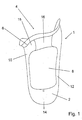
- FIG. 1 shows a prosthesis stem 1 according to an embodiment of the present invention.
- the prosthesis socket 1 has an outer shaft 2, which comprises a proximal opening 4, which is surrounded by an outer edge edge 6.
- an inner shaft 8 In the interior of the outer shaft 2 is an inner shaft 8, which in the proximal direction, in FIG. 1 So up, beyond the outer edge edge 6 protrudes and limits the prosthesis stem 1 in the proximal direction.
- the outer shaft 2 is made of a rigid material, such as a fiber reinforced plastic. This may be, for example, a carbon fiber composite material, ie a carbon fiber reinforced plastic.
- a rigid material such as a fiber reinforced plastic.
- This may be, for example, a carbon fiber composite material, ie a carbon fiber reinforced plastic.
- the outer shaft 2 has a medial portion 10 and a lateral portion 12, which are connected to one another at a distal end 14 of the outer shaft 2.
- the medial portion 10 and the lateral portion 12 are connected by a flexible and inelastic material 16.
- a proximal portion 15 of the medial portion 10 comprises about 1/3 of the anterior surface in rigid and inelastic design, since it consists of the rigid material of the outer shaft 2.
- This design for example by carbon fiber reinforced plastic, the control capability and secure fixation is ensured at the amputation stump.
- a particularly permanent deformation of the ventral flexible and inelastic material 16 is prevented.
- the region between the medial portion 10 and the lateral portion 12 may also be completely filled with the flexible and inelastic material 16.
- the Senomotorik so the perception of the environment, on the amputation stump significantly improved.
- the inner shaft 8 also consists of a silicone, for example a HTV silicone, its respiratory activity is significantly improved and, in addition, a functional restriction of the musculature of the amputation stump is reduced. The elasticity of the silicone is limited by incorporation of a fabric.
- FIG. 2 shows the prosthesis stem 1 from FIG. 1 in a lateral view. It can be seen that in the outer shaft 2 not only a ventral window 18 is provided, which is bounded at the top by the flexible and inelastic material 16, but that a dorsal window 20 is also provided in the dorsal region, ie in the back. This leads in particular when sitting with the prosthesis shaft 1 shown to a much better perception of the environment on the prosthesis stem.
- connection elements for example screwed connectors
- FIG. 3 shows the prosthesis socket 1 in a dorsal view.
- FIG. 3 is also shown that also on the dorsal side, ie the back, between the medial portion 10 and the lateral portion 12 is an insert of the flexible and inelastic material 16 is.
- This provides in particular when sitting with such a prosthesis stem 1 for a much more comfortable to wear, since it gives the loads occurring on the one hand and deforms the forces occurring accordingly and thus leads to significantly fewer bruises, and on the other hand allows a perception of the environment through a rigid material would not be possible.
- prosthesis shaft 1 are at the distal end 14 connecting means, not shown, to fix a distal prosthesis device on the prosthesis shaft 1 here.
- FIG. 4 shows the inner shaft 8 for the prosthesis stem 1 from the FIGS. 1 to 3 , Also, the inner shaft 8 has a proximal opening 4, which is provided for receiving the amputation stump.
- the inner shaft 8 consists of a flexible and cushioning material, for example one or more layers of silicone.
- a bistable matrix 24 which is represented by intersecting lines. This bistable matrix 24 suppresses the elasticity of the inner shaft 8 in this area.
- the outer shaft 2 Since the outer shaft 2 has its ventral window 18 or its dorsal window 20 in this area, if the elasticity of the inner shaft 8 is too great in this area, the inner shaft 8 may come out with the amputation stump located therein. This is reliably prevented by the bistable matrix 24 and thus, on the one hand, the hold Improved the prosthetic socket 1 on the amputation stump and on the other increases the comfort.
- a distal clip 26 which consists of a rigid solid material, which may be, for example, the same fiber-reinforced plastic from which also the outer shaft 2 consists.
- This distal clip 26 prevents collapse or collapse of the distal end of the inner shaft 8 and at the same time provides support for a valve which can be inserted into a valve opening 28 provided for this purpose.
- This may be, for example, a conventional outlet valve, through which air which may possibly be present between the inner shaft 8 and the amputation stump is pumped out of the intermediate space solely by the pumping movement which occurs when walking with the prosthesis shaft 1.
- a negative pressure between the inner shaft 8 and the amputation stump is maintained and thus achieves a firm connection between the amputation stump and the prosthesis shaft 1.
- FIG. 5 shows the inner shaft 8 from a slightly different perspective. It can be seen a plurality of holes 22, in which, for example, setting nuts can be used, which cooperate with screws inserted into the holes 22 in the outer shaft 2 and so connect the inner shaft 8 with the outer shaft 2 hubok.
- the distal clip 26 is again shown with the valve opening 28 provided therein.
- a new representation of the bistable matrix 24 has been omitted for reasons of clarity.
- the inner shaft 8 has on its inner side via a sliding inner coating, which can be applied for example by means of a CVD method.
- a sliding inner coating which can be applied for example by means of a CVD method.
- This avoids friction and associated skin irritation between the proximal end of the prosthesis shaft 1, which is formed by the inner shaft 8, and the skin of the patient.
- the entry of the patient into the prosthesis socket 1 is significantly facilitated by a sliding coating of the inner shaft 8 on the inside thereof.
Landscapes
- Health & Medical Sciences (AREA)
- Cardiology (AREA)
- Oral & Maxillofacial Surgery (AREA)
- Transplantation (AREA)
- Engineering & Computer Science (AREA)
- Biomedical Technology (AREA)
- Heart & Thoracic Surgery (AREA)
- Vascular Medicine (AREA)
- Life Sciences & Earth Sciences (AREA)
- Animal Behavior & Ethology (AREA)
- General Health & Medical Sciences (AREA)
- Public Health (AREA)
- Veterinary Medicine (AREA)
- Prostheses (AREA)
Description
- Die Erfindung betrifft einen Prothesenschaft für eine Prothese, der Anschlussmittel für eine distale Protheseneinrichtung und einen Außenschaft umfasst, der überwiegend aus einem starren Material gebildet ist und eine proximale Öffnung zum Aufnehmen eines Amputationsstumpfes umfasst, die von einem Außenschaftrand umgeben ist. Derartige Prothesenschäfte sind beispielsweise aus der
DE 10 2006 046 927 A1 sowie derUS 2010/0191348 A1 bekannt. - Derartige Prothesenschäfte sind aus dem Stand der Technik seit langem bekannt und werden insbesondere bei Beinprothesen, beispielsweise bei Amputationen oberhalb des Knies des Patienten, verwendet.
- Bei bekannten Prothesenschäften besteht der Außenschaft beispielsweise vollständig aus einem faserverstärkten Kunststoff, beispielsweise einem kohlefaser- oder glasfaserverstärkten Kunststoff. Diese Materialien sind leicht zu bearbeiten, stabil und weisen dennoch ein sehr geringes Eigengewicht auf. Auf diese Weise ist eine besonders leichte Prothese bzw. ein leichter Prothesenschaft erreichbar, der dennoch über gute Stabilitätseigenschaften verfügt. Insbesondere durch die hohe Eigenstabilität des Außenschaftes wird dem Träger der Prothese ein Gefühl der Sicherheit vermittelt. Durch die hohe Stabilität und Festigkeit des Außenschaftes ist zudem eine sichere und stabile Anbindung distaler Protheseneinrichtungen, wie beispielsweise eines Prothesenfußes oder eines Kniegelenks mit anhängendem Prothesenunterschenkel und -fuß, möglich.
- Nachteilig ist jedoch, dass ein Amputationsstumpf, der sich in einem derartigen Prothesenschaft befindet, von Wahrnehmungen der Umwelt weitestgehend oder sogar völlig abgeschottet wird. Setzt sich der Träger einer Prothese, die mit einem gattungsgemäßen Prothesenschaft ausgerüstet ist, beispielsweise hin und stützt die Arme auf die Oberschenkel, hat er aufgrund des starren Außenschaftes des Prothesenschaftes keine Möglichkeit, von seinem Amputationsstumpf eine entsprechende Rückmeldung zu erhalten. Daher kommt es zu einem unnatürlichen und künstlichen Gefühl, das den Tragekomfort einer mit einem derartigen Prothesenschaft ausgestatteten Prothese deutlich mindert.
- Aus der
EP 0 760 640 B1 ist daher ein Prothesenschaft bekannt, bei dem der Außenschaft lediglich in Form einer Aufnahmeschale gebildet ist, in der das distale Ende des Amputationsstumpfes eingesetzt wird. Von dieser Aufnahmeschale ausgehend erstrecken sich drei Schaftfinger zum proximalen Ende des Prothesenschaftes. Diese Schaftfinger sind aus einem starren und haltbaren Material gefertigt und weisen an der Innenseite, also der dem Amputationsstumpf zugewandten Seite, einen Klettverschluss auf. Über den Amputationsstumpf selbst wird ein Innenschaft gezogen, der an entsprechenden Stellen ebenfalls über Klettverschlusselemente verfügt. Durch ein Zusammenwirken der Klettverschlusselemente am Innenschaft und an der Innenseite des Außenschaftes wird der Außenschaft am Innenschaft festgelegt. Nachteilig ist jedoch zum einen, dass es aufgrund der Verwendung von Klettverschlüssen zu Relativbewegungen zwischen dem Innenschaft und dem Außenschaft kommen kann, insbesondere in der Schwungphase einer Gehbewegung. Nachteilig ist zum anderen, dass insbesondere im proximalen Bereich des Prothesenschaftes relativ wenig Halt vorhanden ist, da der starre Außenschaft sich nicht bis in diesen Bereich erstreckt. Für den Patienten ergibt sich somit gegebenenfalls ein Gefühl unzureichender Kontrolle über die Prothese, was zu einer erhöhten Unsicherheit und damit zu einer Verminderung des Tragekomforts führt. - Aus der
US 5,246,464 ist ein Prothesenschaft bekannt, der über einen starren Außenschaft verfügt, der an einigen Stellen durchbrochen ist. Dennoch verfügt der Außenschaft über einen Außenschaftrand, der den gesamten Umfang des Amputationsstumpfes umläuft, und das proximale Ende bzw. den proximalen Rand des Außenschaftes definiert. Durch die vorgesehenen Durchbrechungen im starren und festen Außenschaft kann ein sich in dem Prothesenschaft befindender Amputationsstumpf die Umwelt zumindest in begrenztem Maße wahrnehmen. Insbesondere am Amputationsstumpf anliegende Gegenstände oder andere Körperteile des Patienten, wie beispielsweise aufgestützte Ellbogen, können innerhalb dieser Fenster, die in dem Außenschaft vorgesehen sind, wahrgenommen werden. Da ein derartiger Außenschaft jedoch über einen über den gesamten Umfang umlaufenden Außenschaftrand verfügt, kann es hier noch immer zu Druckstellen und Einschneidungen kommen, die zu schmerzhaften Wunden oder Blessuren führen können. - Die
DE 10 2006 046 927 A1 , dieUS 2004/0158332 A1 , dieUS 2010/0191348 A1 und dieUS 5,653,766 offenbaren jeweils einen Prothesenschaft, der über starre Schalenelemente verfügt, die über Gurte und Gurtelemente aneinander befestigt werden können, sodass auf diese Weise der Prothesenschaft am Amputationsstumpf des Trägers befestigt werden kann. Dabei ist jeweils ein Innenschaft vorgesehen, der aus einem elastischen Material besteht, um den Tragekomfort zu erhöhen. - Die
EP 1 854 621 A1 offenbart ein Verfahren zum Gießen eines Prothesenschaftes, bei dem unterschiedliche weich-elastische Polyurethanlagen verwendet werden. Aus dem Stand der Technik sind daher auch Prothesenschäfte bekannt, die über einen starren Außenschaft verfügen, wobei jedoch der Außenschaftrand, der die proximale Öffnung des Außenschaftes begrenzt, zumindest teilweise durch Gurte gebildet wird. Da diese zumindest in diesen Bereichen des Außenschaftrandes für die Stabilität des Außenschaftes selbst und für die sichere Anordnung des Prothesenschaftes am Amputationsstumpf verantwortlich sind, müssen diese Gurte relativ stramm und fest angezogen werden. Dadurch kommt es zu einem erhöhten Druck auf den Amputationsstumpf im Vergleich zu einem beispielsweise vollständig aus einem starren Material bestehenden Außenschaft. Dieser erhöhte Druck auf den Amputationsstumpf im Bereich der Gurte kann für den Träger sehr unangenehm und gegebenenfalls sogar schmerzhaft werden und zu Druckstellen und Blessuren führen. - Der Erfindung liegt daher die Aufgabe zugrunde, einen Prothesenschaft vorzuschlagen, mit dem eine verbesserte Wahrnehmung der Umwelt durch den Amputationsstumpf ermöglicht wird und der gleichzeitig einen sicheren Halt am Amputationsstumpf gewährleistet und auch bei unterschiedlichen Bewegungen nicht zu Druckstellen führt und die Steuerfähigkeit nicht beeinträchtigt.
- Die Erfindung löst die gestellte Aufgabe durch einen Prothesenschaft der eingangs erwähnten Art, bei dem der Außenschaftrand in einem ventralen Bereich aus einem flexiblen und unelastischen Material gebildet ist, das so ausgebildet ist, dass es unter Einwirkung der herkömmlicherweise beim Tragen des Prothesenschaftes auftretenden Belastungen zu flexiblen Verformungen, nicht jedoch zu einer Aufweitung der proximalen Öffnung kommt, wobei das flexible und unelastische Material an eine erwartete Körperform eines Trägers des Prothesenschaftes anpassbar ist, wobei diese Form nach Ausformen des flexiblen und unelastischen Materials eine Ruheposition des flexiblen und unelastischen Materials bildet, in die es zurückkehrt, sofern es nicht anderen Kräften unterworfen ist.
- Derartige Materialien, insbesondere Dyneema®-verstärkter Kunststoff sind in einem ersten, nicht ausgehärteten Zustand, frei formbar. Sie können insbesondere an die Körperform des späteren Trägers des Prothesenschaftes oder der Prothese angepasst werden. Dabei bedeutet im Kontext der vorliegenden Erfindung eine Anpassung des Materials an die Körperform des Trägers des Prothesenschaftes nicht zwangsläufig, dass eine individuelle Anpassung an jeden einzelnen Träger der Prothese bzw. des Prothesenschaftes vorgenommen werden muss. Vielmehr umfasst die gewählte Formulierung auch eine nur standardmäßige Anpassung des flexiblen und unelastischen Materials an eine erwartete Körperform des Trägers. Diese kann beispielsweise eine Austulpung des Außenschaftrandes umfassen, um so potentielle Druckstellen abzumindern und Blessuren vorzubeugen. Eine derartige Anpassung ist durch eine zumindest teilweise Ausbildung des Schaftrandes durch Gurte nicht zu erreichen.
- Nach dem Ausformen des flexiblen und unelastischen Materiales entsprechend der erwarteten Körperform des Trägers des Prothesenschaftes bildet diese Form die Ruheposition des flexiblen und unelastischen Materials. Dies bedeutet, dass das Material, sofern es nicht anderen Kräften unterworfen ist, in diese Position zurückkehrt. Aufgrund der speziellen Eigenschaften des Materials, insbesondere des Dyneema-faserverstärkten Kunststoffes, hat sich das Material jedoch auch im ausgehärteten Zustand eine Restflexibilität bewahrt, so dass es unter Einwirkung der herkömmlicherweise beim Tragen eines Prothesenschaftes der vorliegenden Art auftretenden Belastungen zu flexiblen Verformungen kommt. Gleichzeitig ist das Material jedoch unelastisch, so dass es beispielsweise nicht zu einer Aufweitung der proximalen Öffnung des Prothesenschaftes kommen kann, wenn eine besondere Belastung des flexiblen und unelastischen Materials vorliegt. Dadurch wird ein sicherer Halt des Prothesenschaftes am Amputationsstumpf des Trägers des Prothesenschaftes gewährleistet.
- Wird ein erfindungsgemäßer Prothesenschaft beispielsweise für die Prothese eines Patienten verwendet, dessen Bein oberhalb des Knies amputiert werden musste, kommt es insbesondere im Bereich des Außenschaftrandes zu einer erhöhten Belastung. Bei Prothesenschäften aus dem Stand der Technik kommt es dadurch in diesem Bereich am Amputationsstumpf zu Druckstellen und gegebenenfalls schmerzhaften Wunden. Durch die erfindungsgemäße Ausgestaltung hingegen ist der Außenschaft im Bereich des Außenschaftrandes durch das flexible und unelastische Material jedoch auch flexibel genug, um aufgrund der in diesem Fall auftretenden Belastungen seine Form zu ändern. Die Gefahr von Druckstellen oder durch Scheuern hervorgerufenen Wunden wird auf diese Weise deutlich verringert.
- Gleichzeitig ist es für den Träger des Prothesenschaftes bzw. einer damit ausgerüsteten Prothese aufgrund der Flexibilität des in diesem Bereich des Außenschaftes verwendeten Materials möglich, Einflüsse der Umgebung, wie beispielsweise auf den Prothesenschaft abgelegte Gegenstände oder Körperteile, wahrzunehmen und somit ein natürlicheres Geführ für die Prothese zu entwickeln. Dadurch steigt der Tragekomfort der Prothese und des Prothesenschaftes, so dass ein natürlicherer Umgang mit der Prothese möglich wird.
- Als bevorzugtes flexibles und unelastisches Material wird ein mit Dyneemafasern verstärkter Kunststoff verwendet. Bei Dyneema-Fasern handelt es sich um Polyethylenfasern, die hoch überstreckt sind. Vergleichbare Fasern werden beispielsweise unter der Markenbezeichnung "Spektra" am Markt angeboten. Derartige Fasern und mit ihnen verstärkter Kunststoff sind besonders einfach zu verarbeiten und weisen alle benötigten Eigenschaften auf. Alternativ können auch Polyamidfasern, beispielsweise Kevlar, verwendet werden. Dabei ist es nicht nötig, dass die Fasern über die gesamte Fläche mit einem Kunststoff beschichtet oder mit diesem getränkt oder in diesen eingebettet sind. In den Randbereichen der durch die Fasern gebildeten Flächen, also der Flächen, die durch das flexible und unelastische Material gebildet werden, ist die Verwendung eines derartigen Kunststoffs jedoch vorteilhaft, da so eine einfache Anbindung an das starre Material des Außenschaftes ermöglicht wird.
- In einer bevorzugten Ausführungsform ist das starre Material des Außenschaftes ebenfalls ein faserverstärkter Kunststoff. Dabei handelt es sich vorteilhafterweise um einen glasfaser- oder kohlefaserverstärkten Kunststoff. Diese Materialien weisen die bereits genannten Vorteile des geringen Eigengewichtes, der hohen Stabilität und der leichten Verarbeitbarkeit auf. Über die hohe Eigenstabilität des Außenschaftes bleibt die Steuerfähigkeit der Prothese erhalten, wobei insbesondere bei einem Oberschenkelschaft eine rigide Anlage für die Steuerung vorteilhaft ist.
- In einer besonders bevorzugten Ausführungsform kann für das starre Material und das flexible und unelastische Material der gleiche Kunststoff verwendet werden. Dadurch kann eine dafür vorgesehene Form in einem Arbeitsschritt in den jeweiligen Bereichen mit den jeweiligen faserverstärkten Kunststoff ausgelegt werden. Zudem können die beiden faserverstärkten Kunststoffe gleichzeitig aushärten und so eine besonders feste, insbesondere stoffschlüssige Verbindung eingehen. Dadurch kommt es zu einer erhöhten Stabilität insbesondere im Kontaktbereich der beiden faserverstärkten Kunststoffe am Prothesenschaft. Dadurch wird die Lebensdauer des Prothesenschaftes deutlich verlängert. Zudem entsteht zwischen den beiden aneinander angrenzenden Materialien keine Grenzschicht oder gar ein Absatz, der den Tragekomfort eines derartigen Prothesenschaftes deutlich verringert würde.
- Vorzugsweise ist der Außenschaftrand in einem dorsalen Bereich aus dem flexiblen und unelastischen Material gebildet. Insbesondere bei Patienten, deren Bein oberhalb des Knies amputiert werden musste, ist der dorsale, also hintere Bereich des Außenschaftrandes der Bereich, der beim Hinsetzen am meisten belastet wird, wenn dabei die Prothese mit dem beschriebenen Prothesenschaft getragen wird. Der Patient setzt sich praktisch auf den Außenschaftrand. Ist dieser starr, stabil und hart ausgebildet, kommt es auch hier zu einem unangenehmen Druck, der zu Druckstellen oder durch Scheuern sogar zu Wunden führen kann. Dadurch, dass auch im dorsalen Bereich ein flexibles und unelastisches Material verwendet wird, kann diesen Beschwerden vorgebeugt werden. Beim Hinsetzen auf den Außenschaftrand verformt sich das flexible und unelastische Material aufgrund seiner Flexibilität, so dass es die für die herrschenden Belastungen optimale Form einnehmen kann, so dass Druckstellen sicher verhindert werden.
- Als besonders vorteilhaft hat sich dabei herausgestellt, wenn das flexible und unelastische Material im dorsalen Bereich des Außenschaftes das gleiche Material ist, wie das flexible und unelastische Material im ventralen Bereich des Außenschaftes. Handelt es sich bei beiden Materialien zudem um einen faserverstärkten, insbesondere Dyneema-faserverstärkten Kunststoff, kann für diesen faserverstärkten Kunststoff beispielsweise wieder der gleiche Kunststoff verwendet werden, wie für den verbleibenden Rest des Außenschaftes, der aus dem starren Material gebildet ist. Auch hier kommt es somit zu den gleichen Vorteilen, die bereits beschrieben wurden, nämlich einer besonders starken, stoffschlüssigen Verbindung und zu einer besonders glatten Innenfläche des Außenschaftes, da Stufen und Absätze zwischen zwei benachbarten Materialien sicher vermieden werden.
- Vorteilhafterweise ist der Außenschaft an zumindest einer Stelle durchbrochen. Derartige Durchbrüche, oder Fenster, reduzieren zum einen das Gewicht des Außenschaftes und geben zudem dem Träger des Prothesenschaftes und der Prothese die Möglichkeit, in diesem Bereich Einflüsse der Außenwelt wahrzunehmen. Dabei ist es denkbar, dass die Durchbrüche oder Fenster vollständig mit dem flexiblen und unelastischen Material ausgefüllt sind. Alternativ dazu ist es auch möglich, in diesen Durchbrüchen kein Material vorzusehen, da der Prothesenschaft der Prothese einen über weite Bereiche starren Außenschaft verfügt, ist es vorteilhaft, wenn zwischen dem starren Außenschaft und dem Amputationsstumpf eine polsternde Schicht vorgesehen wird. Diese kann beispielsweise in Form eines Liner oder eines Sleeve über den Amputationsstumpf gezogen werden. Als besonders vorteilhaft hat sich jedoch herausgestellt, wenn innerhalb des Außenschaftes ein Innenschaft aus einem flexiblen Material angeordnet ist. Dies kann beispielsweise ein Silikonschaft sein, der vorteilhafterweise im proximalen Bereich eine Antihaftbeschichtung, beispielsweise mittels CVD-Verfahren, aufweist. Dadurch wird der Einstieg des Patienten in den Innenschaft deutlich erleichtert, weil die Haftreibung des Innenschaftes am Amputationsstumpf in diesem Bereich deutlich reduziert wird. Ein solcher Innenschaft kann beispielsweise zwei Lagen HTV Silikon umfassen. Derartige Innenschäfte können mit polsternden Verdickungen oder an besonders zu polsternden Stellen, beispielsweise geklebte Polsterpads, ausgestattet sein. Diese können gegebenenfalls für jeden Patienten individuell hergestellt, angepasst und angeordnet werden. Vorzugsweise ist im Bereich der Fensterung die Elastizität des Silikons minimiert. Dies wird idealerweise durch die Einarbeitung von Gewebe in die Silikonschichten erreicht. Die proximalen Ränder des Innenschaftes bleiben elastisch verformbar.
- Ein Innenschaft umfasst vorzugsweise eine an einem distalen Ende angeordnete integrierte Spange, die aus einem stabilen Material, beispielsweise ein faserverstärkten Kunststoff hergestellt sein kann. Diese verhindert ein Zusammenfallen oder Implodieren des Innenschaftes und bietet gleichzeitig beispielsweise Halt und Stabilität für einen Ventilanschluss eines Ventils, durch das, gegebenenfalls mit einer separaten Pumpe ein Unterdruck zwischen dem Innenschaft und dem Amputationsstumpf hergestellt wird, durch den der Prothesenschaft am Amputationsstumpf gehalten wird.
- Werden die Fenster bzw. Durchbrüche im Außenschaft des Prothesenschaftes mit dem flexiblen und unelastischen Material ausgefüllt, ist es für den Träger des Prothesenschaftes weiterhin möglich, hier Umwelteinflüsse wahrzunehmen. Gleichzeitig wird jedoch sicher verhindert, dass Teile des Amputationsstumpfes insbesondere beim Auftreten mit einer derartigen Prothese aus diesen Durchbrüchen und Fenstern herausquellen. Auf diese Weise wird auch ein sogenannter Melkeffekt verhindert und der Tragekomfort der Prothese weiter erhöht.
- Dazu ist es von Vorteil, wenn der Innenschaft mit dem Außenschaft hubfrei, verbunden ist. Dies erfolgt in einer besonders vorteilhaften Ausgestaltung durch wenigstens eine insbesondere distale Schraubverbindung, mit der der Innenschaft mit dem Außenschaft verbunden ist. Vorzugsweise ist der Innenschaft distal, insbesondere durch eine Verschraubung, mit dem Außenschaft verbunden.
- Bei aus dem Stand der Technik bekannten Verbindungssystemen, beispielsweise über Klettverschlüsse, ist es denkbar, dass insbesondere in der Schwungphase einer Beinprothese die auf die Prothese wirkenden Zugkräfte dazu führen, dass es zwischen dem an der distalen Protheseneinrichtung festgelegten Außenschaft und dem am Amputationsstumpf festliegenden Innenschaft zu einer Relativbewegung kommt. Für den Träger der Prothese fühlt sich eine derartige Relativbewegung so an, als wäre die Prothese lose und nicht in vollständig funktionstüchtiger Weise am Amputationsstumpf festgelegt. Eine derartige Relativbewegung zwischen dem Außenschaft und dem Innenschaft hat somit ein erhebliches Unsicherheitsgefühl zur Folge, das durch die insbesondere hubfreie Befestigung des Innenschaftes am Außenschaft sicher verhindert wird.
- In einer bevorzugten Ausführungsform ist es möglich, dass flexible und unelastische Material in zwei Teilen auszubilden, die beispielsweise über einen Klettverschluss oder einen an der Außenseite befestigten Gurt miteinander verbindbar sind. Auf diese Weise können die Vorteile des flexiblen und unelastischen Materials, das der Körperform des Trägers angepasst ist, mit den Vorteilen der Verstellbarkeit über ein Gurtsystem oder eine sonstige Verschließeinrichtung kombiniert werden. Auf diese Weise ist es insbesondere möglich, den Prothesenschaft über einen langen Zeitraum bei einem Patienten zu verwenden, auch wenn sich beispielsweise das Volumen des Amputationsstumpfes über die Jahre ändert. Eine individuelle Anpassung der Größe des Prothesenschaftes ist auf diese Weise in einem begrenzten Rahmen möglich.
- Die Größe des ventralen Bereichs, in dem der Außenschaft aus dem flexiblen und unelastischen Material gebildet ist, kann dabei sowohl in Umfangsrichtung als auch in einer Ausdehnung von der proximalen Öffnung hin zum distalen Ende des Prothesenschaftes stark variieren. So ist es möglich, in dieser Richtung die Ausdehnung des ventralen Bereiches auf wenige Zentimeter zu beschränken. Alternativ dazu kann auch ein Bereich mit dem flexiblen und unelastischen Material vorgesehen sein, der sich über mehr als die Hälfte der Ausdehnung des Außenschaftes in dieser Richtung erstreckt.
- Mit Hilfe einer Zeichnung wird nachfolgend ein Ausführungsbeispiel der vorliegenden Erfindung näher erläutert. Es zeigt
- Figur 1
- - einen Prothesenschaft gemäß einem ersten Ausführungsbeispiel der vorliegenden Erfindung,
- Figur 2
- - einen Prothesenschaft gemäß einem Ausführungsbeispiel der vorliegenden Erfindung,
- Figur 3
- - einen Prothesenschaft gemäß einem weiteren Ausführungsbeispiel der vorliegenden Erfindung,
- Figur 4
- - einen Innenschaft für einen Prothesenschaft gemäß einem Ausführungsbeispiel der vorliegenden Erfindung, und
- Figur 5
- - den Innenschaft aus
Figur 4 aus einem anderen Blickwinkel. -
Figur 1 zeigt einen Prothesenschaft 1 gemäß einem Ausführungsbeispiel der vorliegenden Erfindung. Der Prothesenschaft 1 verfügt über einen Außenschaft 2, der eine proximale Öffnung 4 umfasst, die von einem Außenschaftrand 6 umgeben ist. Im Innern des Außenschaftes 2 befindet sich ein Innenschaft 8, der in proximaler Richtung, inFigur 1 also nach oben, über den Außenschaftrand 6 hervorsteht und den Prothesenschaft 1 in proximaler Richtung begrenzt. - Der Außenschaft 2 besteht aus einem starren Material, beispielsweise einem faserverstärktem Kunststoff. Dabei kann es sich beispielsweise um einen Kohlefaserverbundwerkstoff, also einen kohlefaserverstärkten Kunststoff handeln. Durch den in proximaler Richtung über den Außenschaftrand 6 hervorstehenden Innenschaft 8 wird der harte und starre Außenschaftrand 6 für den Träger der Prothese beziehungsweise des Prothesenschaftes 1 gepolstert.
- Man erkennt, dass der Außenschaft 2 einen medialen Anteil 10 und einen lateralen Anteil 12 aufweist, die an einem distalen Ende 14 des Außenschaftes 2 miteinander verbunden sind. Im proximalen Bereich sind der mediale Anteil 10 und der laterale Anteil 12 durch ein flexibles und unelastisches Material 16 verbunden. Dieses befindet sich, wie in
Figur 1 dargestellt, in einem ventralen Bereich des Außenschaftes 2. Ein proximaler Anteil 15 des medialen Anteils 10 umfasst ca. 1/3 der ventralen Fläche in rigider und unelastische Ausführung, da er aus dem starren Material des Außenschaftes 2 besteht. Durch diese Ausführung beispielsweise durch kohlefaserverstärkten Kunststoff wird die Steuerfähigkeit und die sichere Fixierung am Amputationsstumpf sichergestellt. Zusätzlich wird eine insbesondere dauerhafte Verformung des ventralen flexiblen und unelastischen Materials 16 verhindert. - Alternativ zu der in
Figur 1 dargestellten Ausführungsform kann beispielsweise auch der Bereich zwischen dem medialen Anteil 10 und dem lateralen Anteil 12 vollständig mit dem flexiblen und unelastischen Material 16 ausgefüllt sein. Dies hätte den Vorteil, dass ein Herausquillen des Innenschaftes 8 mit dem sich darin befindlichen Amputationsstumpf aus dem zwischen dem medialen Anteil 10 und dem lateralen Anteil 12 gebildeten Fenster verhindert wird. Durch die inFigur 1 gezeigte Ausführungsform wird jedoch die Senomotorik, also die Wahrnehmung der Umwelt, über den Amputationsstumpf deutlich verbessert. Besteht der Innenschaft 8 zudem aus einem Silikon, beispielsweise einem HTV Silikon, wird dessen Atmungsaktivität deutlich verbessert und zudem eine Funktionseinschränkung der Muskulatur des Amputationsstumpfes verringert. Die Elastizität des Silikons wird durch Einarbeitung eines Gewebes eingeschränkt. -
Figur 2 zeigt den Prothesenschaft 1 ausFigur 1 in einer lateralen Ansicht. Man erkennt folglich den lateralen Anteil 12 des Außenschaftes 2 sowie dessen distales Ende 14. Zudem ist zu erkennen, dass in dem Außenschaft 2 nicht nur ein ventrales Fenster 18 vorgesehen ist, das nach oben hin durch das flexible und unelastische Material 16 begrenzt wird, sondern dass auch im dorsalen Bereich, also hinten, ein dorsales Fenster 20 vorgesehen ist. Dies führt insbesondere beim Sitzen mit dem gezeigten Prothesenschaft 1 zu einer deutlich besseren Wahrnehmung der Umgebung über den Prothesenschaft. - Im lateralen Anteil 12 sind zudem mehrere Bohrungen 22 dargestellt, durch die Verbindungselemente, beispielsweise Schraubverbinder, geführt werden können, um den Außenschaft 2 mit dem Innenschaft hubfrei zu verbinden.
-
Figur 3 zeigt den Prothesenschaft 1 in einer dorsalen Ansicht. Man erkennt das dorsale Fenster 20 im Außenschaft 2, durch das der Innenschaft 8 erkennbar ist. InFigur 3 ist zudem dargestellt, dass sich auch auf der dorsalen Seite, also hinten, zwischen dem medialen Anteil 10 und dem lateralen Anteil 12 ein Einsatz aus dem flexiblen und unelastischen Material 16 befindet. Dieser sorgt insbesondere beim Sitzen mit einem derartigen Prothesenschaft 1 für ein deutlich angenehmeres Tragegefühl, da er zum einen den auftretenden Belastungen nachgibt und sich den auftretenden Kräften entsprechend verformt und so zu deutlich weniger Druckstellen führt, und zum anderen eine Wahrnehmung der Umgebung erlaubt, die durch ein starres Material nicht möglich wäre. An dem in denFiguren 1 bis 3 gezeigten Prothesenschaft 1 befinden sich am distalen Ende 14 nicht gezeigte Verbindungsmittel, um hier eine distale Protheseneinrichtung am Prothesenschaft 1 zu befestigen. -
Figur 4 zeigt den Innenschaft 8 für den Prothesenschaft 1 aus denFiguren 1 bis 3 . Auch der Innenschaft 8 verfügt über eine proximale Öffnung 4, die zur Aufnahme des Amputationsstumpfes vorgesehen ist. Der Innenschaft 8 besteht aus einem flexiblen und polsternden Material, beispielsweise einer oder mehrerer Schichten Silikon. Über Bohrungen 22, die auf die Position der Bohrungen 22 im Außenschaft 2, wie sie inFigur 2 dargestellt sind, angepasst sind, lässt sich der Außenschaft 6 mit dem Innenschaft 8 hubfrei verbinden. Man erkennt im mittleren Bereich des Innenschaftes 8 eine bistabile Matrix 24, die durch sich kreuzende Linien dargestellt ist. Diese bistabile Matrix 24 unterbindet die Elastizität des Innenschafts 8 in diesem Bereich. Da der Außenschaft 2 in diesem Bereich sein ventrales Fenster 18 bzw. sein dorsales Fenster 20 aufweist, kann es bei einer zu großen Elastizität des Innenschaftes 8 in diesem Bereich zu einem Herausquillen des Innenschaftes 8 mit dem sich darin befindlichen Amputationsstumpf kommen. Durch die bistabile Matrix 24 wird dies sicher verhindert und so zum einen der Halt des Prothesenschaftes 1 am Amputationsstumpf verbessert und zum anderen der Tragekomfort erhöht. - Im distalen Bereich verfügt der in
Figur 4 gezeigte Innenschaft 8 über eine distale Spange 26, die aus einem starren festen Material besteht, das beispielsweise der gleiche faserverstärkte Kunststoff sein kann, aus dem auch der Außenschaft 2 besteht. Diese distale Spange 26 verhindert ein Kollabieren oder Zusammenfallen des distalen Endes des Innenschaftes 8 und bietet gleichzeitig Halt für ein Ventil, das in eine dafür vorgesehene Ventilöffnung 28 einsetzbar ist. Dieses kann beispielsweise ein herkömmliches Auslassventil sein, durch das allein durch die beim Gehen mit dem Prothesenschaft 1 auftretende Pumpbewegung eventuell zwischen dem Innenschaft 8 und dem Amputationsstumpf befindliche Luft aus dem Zwischenraum herausgepumpt wird. Dadurch wird ein Unterdruck zwischen dem Innenschaft 8 und dem Amputa-tionsstumpf aufrecht erhalten und so eine feste Verbindung zwischen dem Amputationsstumpf und dem Prothesenschaft 1 erreicht. -
Figur 5 zeigt den Innenschaft 8 aus einer leicht geänderten Perspektive. Man erkennt eine Mehrzahl Bohrungen 22, in die beispielsweise Setzmuttern eingesetzt werden können, die mit in die Bohrungen 22 im Außenschaft 2 eingesetzten Schrauben zusammenwirken und so den Innenschaft 8 mit dem Außenschaft 2 hubfrei verbinden. Im distalen Bereich des Innenschaftes 8 ist wieder die distale Spange 26 mit der darin vorgesehenen Ventilöffnung 28 dargestellt. Auf eine erneute Darstellung der bistabilen Matrix 24 wurde aus Gründen der Übersichtlichkeit verzichtet. - In einer bevorzugten Ausführungsform verfügt der Innenschaft 8 auf seiner Innenseite über eine gleitende Innenbeschichtung, die beispielsweise mittels eines CVD-Verfahrens aufgebracht werden kann. Damit wird eine Reibung und eine damit verbundene Hautreizung zwischen dem proximalen Ende des Prothesenschaftes 1, das durch den Innenschaft 8 gebildet wird, und der Haut des Patienten vermieden. Eine gleitende Beschichtung auf der Außenseite des Innenschaftes 8 ist insbesondere im proximalen Anteil des Innenschaftes 8, der den Außenschaftrand 6 proximal überragt, sinnvoll. Auf diese Weise wird eine Reibung und eine Haftung zwischen dem Innenschaft 8 und der Kleidung des Patienten verhindert. Gleichzeitig wird durch eine gleitende Beschichtung des Innenschaftes 8 an dessen Innenseite der Einstieg des Patienten in den Prothesenschaft 1 deutlich erleichtert.
-
- 1
- Prothesenschaft
- 2
- Außenschaft
- 4
- Proximale Öffnung
- 6
- Außenschaftrand
- 8
- Innenschaft
- 10
- Medialer Anteil
- 12
- Lateraler Anteil
- 14
- Distales Ende
- 15
- Proximaler Bereich
- 16
- Flexibles und unelastisches Material
- 18
- Ventrales Fenster
- 20
- Dorsales Fenster
- 22
- Bohrung
- 24
- Bistabile Matrix
- 26
- Distale Spange
- 28
- Ventilöffnung
Claims (10)
- Prothesenschaft (1) für eine Prothese, der
Anschlussmittel für eine distale Protheseneinrichtung und
einen Außenschaft (2) aufweist, der
überwiegend aus einem starren Material gebildet ist und
eine proximale Öffnung (4) zum Aufnehmen eines Amputationsstumpfes umfasst, die von einem Außenschaftrand (6) umgeben ist, wobei
der Außenschaftrand (6) in einem ventralen Bereich aus einem flexiblen und unelastischen Material (16) gebildet ist, das so ausgebildet ist, dass es unter Einwirkung der herkömmlicherweise beim Tragen des Prothesenschaftes auftretenden Belastungen zu flexiblen Verformungen, nicht jedoch zu einer Aufweitung der proximalen Öffnung (4) kommt, wobei das flexible und unelastische Material (16) an eine erwartete Körperform eines Trägers des Prothesenschaftes (1) anpassbar ist, wobei diese Form nach Ausformen des flexiblen und unelastischen Materials (16) eine Ruheposition des flexiblen und unelastischen Materials (16) bildet, in die es zurückkehrt, sofern es nicht anderen Kräften unterworfen ist. - Prothesenschaft (1) nach Anspruch 1, dadurch gekennzeichnet, dass das flexible und unelastische Material ein faserverstärkter Kunststoff ist, der insbesondere Dyneema®-Fasern umfasst.
- Prothesenschaft (1) nach Anspruch 1 oder 2, dadurch gekennzeichnet, dass das starre Material ein faserverstärkter Kunststoff ist.
- Prothesenschaft (1) nach Anspruch 3, dadurch gekennzeichnet, dass das starre Material und das flexible und unelastische Material (16) den gleichen Kunststoff umfasst.
- Prothesenschaft (1) nach einem der vorstehenden Ansprüche, dadurch gekennzeichnet, dass der Außenschaftrand (6) in einem dorsalen Bereich aus dem flexiblen und unelastischen Material (16) gebildet ist.
- Prothesenschaft (1) nach Anspruch 5, dadurch gekennzeichnet, dass das flexible und unelastische Material (16) im dorsalen Bereich des Außenschaftrandes (6) das gleiche Material ist, wie das flexible und unelastische Material (16) im ventralen Bereich des Außenschaftrandes (6).
- Prothesenschaft (1) nach einem der vorstehenden Ansprüche, dadurch gekennzeichnet, dass der Außenschaft (2) an zumindest einer Stelle durchbrochen ist.
- Prothesenschaft (1) nach einem der vorstehenden Ansprüche, dadurch gekennzeichnet, dass in dem Außenschaft (2) ein Innenschaft (8) aus einem flexiblen Material angeordnet ist.
- Prothesenschaft (1) nach Anspruch 8, dadurch gekennzeichnet, dass der Innenschaft (8) mit dem Außenschaft (2) hubfrei verbunden ist.
- Prothesenschaft (1) nach Anspruch 9, dadurch gekennzeichnet, dass der Innenschaft (8) mit dem Außenschaft (2) durch wenigstens eine insbesondere distale Schraubverbindung verbunden ist.
Priority Applications (1)
| Application Number | Priority Date | Filing Date | Title |
|---|---|---|---|
| PL12788117T PL2773295T3 (pl) | 2011-11-03 | 2012-10-30 | Lej protezy |
Applications Claiming Priority (2)
| Application Number | Priority Date | Filing Date | Title |
|---|---|---|---|
| DE102011117801A DE102011117801A1 (de) | 2011-11-03 | 2011-11-03 | Prothesenschaft |
| PCT/EP2012/004536 WO2013064240A1 (de) | 2011-11-03 | 2012-10-30 | Prothesenschaft |
Publications (2)
| Publication Number | Publication Date |
|---|---|
| EP2773295A1 EP2773295A1 (de) | 2014-09-10 |
| EP2773295B1 true EP2773295B1 (de) | 2018-02-14 |
Family
ID=48128949
Family Applications (1)
| Application Number | Title | Priority Date | Filing Date |
|---|---|---|---|
| EP12788117.5A Active EP2773295B1 (de) | 2011-11-03 | 2012-10-30 | Prothesenschaft |
Country Status (6)
| Country | Link |
|---|---|
| US (1) | US10226365B2 (de) |
| EP (1) | EP2773295B1 (de) |
| BR (1) | BR112014010595A2 (de) |
| DE (1) | DE102011117801A1 (de) |
| PL (1) | PL2773295T3 (de) |
| WO (1) | WO2013064240A1 (de) |
Families Citing this family (10)
| Publication number | Priority date | Publication date | Assignee | Title |
|---|---|---|---|---|
| US10842653B2 (en) | 2007-09-19 | 2020-11-24 | Ability Dynamics, Llc | Vacuum system for a prosthetic foot |
| EP3033052B1 (de) | 2013-08-13 | 2018-06-06 | Ossur Iceland EHF | Randbefestigung mit einem dichtungselement für einen prothesenschaft |
| DE202016008362U1 (de) | 2015-02-26 | 2017-08-25 | Andreas Radspieler | Vorrichtung und Set zum Erstellen eines Gipsabdrucks eines Körpergliedstumpfs eines Patienten zum Fertigen eines Prothesenschafts |
| FR3037497A1 (fr) * | 2015-06-18 | 2016-12-23 | Chabloz Composants | Piece de jonction entre une emboiture prothetique et un membre prothetique. |
| DE102017129930B4 (de) | 2017-12-14 | 2019-07-04 | Ottobock Se & Co. Kgaa | Prothesenschaftsystem |
| WO2020099435A1 (de) * | 2018-11-12 | 2020-05-22 | Romedis Gmbh | Verfahren zum fertigen von abschnitten eines prothesenschafts und kit |
| DE102019132290A1 (de) * | 2019-11-28 | 2021-06-02 | Otto Bock Healthcare Products Gmbh | Prothesenschaft und Verfahren zu dessen Herstellung |
| CN112706345B (zh) * | 2020-12-07 | 2024-12-24 | 佛山市工巧医疗器械有限公司 | 一种内衬套成型装置及内衬套成型工艺 |
| TR2023002045A2 (tr) * | 2023-02-23 | 2023-03-21 | Oezyegin Ueniversitesi | Konforlu bi̇r protez soketi̇ |
| DE102023107883A1 (de) | 2023-03-28 | 2024-10-02 | Horus Prosthetics GmbH | Prothesenschaft und verfahren zur herstellung eines prothesenschafts |
Citations (1)
| Publication number | Priority date | Publication date | Assignee | Title |
|---|---|---|---|---|
| US5653766A (en) * | 1996-02-23 | 1997-08-05 | Michigan Orthopedic Services, Llc | Post-operative prosthetic device |
Family Cites Families (16)
| Publication number | Priority date | Publication date | Assignee | Title |
|---|---|---|---|---|
| GB515970A (en) * | 1938-06-17 | 1939-12-19 | Charles Whitfield Eddels | Improvements in and relating to artificial limbs and the like |
| DE824678C (de) * | 1948-11-14 | 1951-12-13 | Walter Ebert | Kuenstliches Bein fuer Unterschenkelamputierte |
| DE2601906A1 (de) * | 1976-01-20 | 1977-07-21 | Menzel Geb Stueberitz Edith | Verstellvorrichtung fuer oberschenkelschafte von beinprothesen |
| SU1685427A1 (ru) * | 1988-03-01 | 1991-10-23 | Украинский Научно-Исследовательский Институт Протезирования, Протезостроения, Экспертизы И Восстановления Трудоспособности Инвалидов | Приемна гильза протеза конечности |
| US5393303A (en) * | 1991-04-17 | 1995-02-28 | Alcare Co., Ltd. | Attachment for leg and foot joint |
| US5246464A (en) | 1992-05-08 | 1993-09-21 | Sabolich, Inc. | Artificial limb with anatomically-configured socket |
| DE9408556U1 (de) | 1994-05-25 | 1994-07-21 | Biedermann Motech GmbH, 78054 Villingen-Schwenningen | Testprothese |
| SE511603C2 (sv) * | 1997-11-27 | 1999-10-25 | Finn Gramnaes | Låsanordning avsedd som fästelement för en protes |
| WO2003013400A1 (de) | 2001-08-02 | 2003-02-20 | Sanitätshaus Carstens Im Marienpark G.M.B.H. | Prothese |
| FR2828093B1 (fr) * | 2001-08-06 | 2004-06-25 | Renaissance Sanitaire | Emboiture souple pour la prothetisation d'une personne amputee du membre superieur |
| US7488349B2 (en) * | 2006-03-24 | 2009-02-10 | Ossur Hf | Ventilated prosthesis system |
| DE102006021857A1 (de) | 2006-05-09 | 2007-11-15 | Otto Bock Healthcare Ip Gmbh & Co. Kg | Verfahren zum Gießen eines Prothesenschaftes |
| DE102006046928B4 (de) * | 2006-09-29 | 2012-03-08 | Otto Bock Healthcare Gmbh | Prothese mit einem Schaft zur Aufnahme eines Amputationsstumpfes |
| DE102006046927A1 (de) * | 2006-09-29 | 2008-04-03 | Otto Bock Healthcare Ip Gmbh & Co. Kg | Prothese mit einem Schaft zur Aufnahme eines Amputationsstumpfes |
| DE102007005648A1 (de) * | 2007-01-31 | 2008-08-14 | Bernhard Sacherer | Vorrichtung und Verfahren zur Herstellung eines orthopädischen Hilfsmittels sowie entsprechendes Hilfsmittel |
| DE102007035410A1 (de) * | 2007-07-26 | 2009-02-19 | Otto Bock Healthcare Ip Gmbh & Co. Kg | Prothesenschaft zur Aufnahme eines Amputationsstumpfes einer Extremität und System aus Prothesenschaft und Protheseneinrichtung |
-
2011
- 2011-11-03 DE DE102011117801A patent/DE102011117801A1/de not_active Withdrawn
-
2012
- 2012-10-30 PL PL12788117T patent/PL2773295T3/pl unknown
- 2012-10-30 US US14/355,482 patent/US10226365B2/en active Active
- 2012-10-30 WO PCT/EP2012/004536 patent/WO2013064240A1/de not_active Ceased
- 2012-10-30 BR BR112014010595A patent/BR112014010595A2/pt not_active Application Discontinuation
- 2012-10-30 EP EP12788117.5A patent/EP2773295B1/de active Active
Patent Citations (1)
| Publication number | Priority date | Publication date | Assignee | Title |
|---|---|---|---|---|
| US5653766A (en) * | 1996-02-23 | 1997-08-05 | Michigan Orthopedic Services, Llc | Post-operative prosthetic device |
Also Published As
| Publication number | Publication date |
|---|---|
| PL2773295T3 (pl) | 2018-07-31 |
| US10226365B2 (en) | 2019-03-12 |
| US20140288668A1 (en) | 2014-09-25 |
| WO2013064240A1 (de) | 2013-05-10 |
| DE102011117801A1 (de) | 2013-05-08 |
| EP2773295A1 (de) | 2014-09-10 |
| BR112014010595A2 (pt) | 2017-05-02 |
Similar Documents
| Publication | Publication Date | Title |
|---|---|---|
| EP2773295A1 (de) | Prothesenschaft | |
| DE60115216T2 (de) | Vakuumpumpe und stossdämpfer für kunstglieder | |
| EP3100704B1 (de) | Prothesenschaft und system aus prothesenschaft und protheseneinrichtung | |
| DE60307833T2 (de) | Pulsierende druckkammer in einer prothetischen gliedmasse | |
| DE60315698T2 (de) | FUßGELENKORTHOSE | |
| DE102012017324B4 (de) | Liner für eine Prothese | |
| EP4108213B1 (de) | Prothesenliner | |
| EP2066268A1 (de) | Prothese mit einem schaft zur aufnahme eines amputationsstumpfes | |
| WO2013079159A1 (de) | Prothesenkosmetik | |
| EP3328323B1 (de) | Prothesenschafthaltevorrichtung und system aus prothesenschaft und prothesenschafthaltevorrichtung | |
| DE102014001000A1 (de) | Verbindungseinrichtung zum Verbinden zumindest einer prothetischen Einrichtung mit einem Körperstumpf einer Person sowie entsprechend ausgerüstete prothetische Einrichtung und Zwischenelement mit einer solchen Verbindungseinrichtung | |
| EP3229741B1 (de) | Anpassbarer prothesenschaft für die untere extremität | |
| WO2008040291A1 (de) | Prothese mit einem schaft zur aufnahme eines amputationsstumpfes | |
| DE102012017213B3 (de) | Prothesenschaft | |
| EP3723670B1 (de) | Prothesenschaftsystem | |
| DE69726021T2 (de) | Unterdruck kontrolliertes künstliches gliedmass mit doppelgelenkpfanne und verriegelungsmechanismus | |
| DE102016104319B3 (de) | Prothetischer Liner und Prothesenschaft-Liner-System | |
| WO2020245094A1 (de) | Prothese zum klettern und/oder bouldern |
Legal Events
| Date | Code | Title | Description |
|---|---|---|---|
| PUAI | Public reference made under article 153(3) epc to a published international application that has entered the european phase |
Free format text: ORIGINAL CODE: 0009012 |
|
| 17P | Request for examination filed |
Effective date: 20140520 |
|
| AK | Designated contracting states |
Kind code of ref document: A1 Designated state(s): AL AT BE BG CH CY CZ DE DK EE ES FI FR GB GR HR HU IE IS IT LI LT LU LV MC MK MT NL NO PL PT RO RS SE SI SK SM TR |
|
| DAX | Request for extension of the european patent (deleted) | ||
| 17Q | First examination report despatched |
Effective date: 20150427 |
|
| STAA | Information on the status of an ep patent application or granted ep patent |
Free format text: STATUS: EXAMINATION IS IN PROGRESS |
|
| GRAP | Despatch of communication of intention to grant a patent |
Free format text: ORIGINAL CODE: EPIDOSNIGR1 |
|
| STAA | Information on the status of an ep patent application or granted ep patent |
Free format text: STATUS: GRANT OF PATENT IS INTENDED |
|
| INTG | Intention to grant announced |
Effective date: 20170927 |
|
| GRAS | Grant fee paid |
Free format text: ORIGINAL CODE: EPIDOSNIGR3 |
|
| GRAA | (expected) grant |
Free format text: ORIGINAL CODE: 0009210 |
|
| STAA | Information on the status of an ep patent application or granted ep patent |
Free format text: STATUS: THE PATENT HAS BEEN GRANTED |
|
| AK | Designated contracting states |
Kind code of ref document: B1 Designated state(s): AL AT BE BG CH CY CZ DE DK EE ES FI FR GB GR HR HU IE IS IT LI LT LU LV MC MK MT NL NO PL PT RO RS SE SI SK SM TR |
|
| REG | Reference to a national code |
Ref country code: GB Ref legal event code: FG4D Free format text: NOT ENGLISH |
|
| REG | Reference to a national code |
Ref country code: CH Ref legal event code: EP |
|
| REG | Reference to a national code |
Ref country code: IE Ref legal event code: FG4D Free format text: LANGUAGE OF EP DOCUMENT: GERMAN |
|
| REG | Reference to a national code |
Ref country code: DE Ref legal event code: R096 Ref document number: 502012012158 Country of ref document: DE Ref country code: AT Ref legal event code: REF Ref document number: 969382 Country of ref document: AT Kind code of ref document: T Effective date: 20180315 |
|
| REG | Reference to a national code |
Ref country code: SE Ref legal event code: TRGR |
|
| REG | Reference to a national code |
Ref country code: NL Ref legal event code: MP Effective date: 20180214 |
|
| PG25 | Lapsed in a contracting state [announced via postgrant information from national office to epo] |
Ref country code: HR Free format text: LAPSE BECAUSE OF FAILURE TO SUBMIT A TRANSLATION OF THE DESCRIPTION OR TO PAY THE FEE WITHIN THE PRESCRIBED TIME-LIMIT Effective date: 20180214 Ref country code: NL Free format text: LAPSE BECAUSE OF FAILURE TO SUBMIT A TRANSLATION OF THE DESCRIPTION OR TO PAY THE FEE WITHIN THE PRESCRIBED TIME-LIMIT Effective date: 20180214 Ref country code: LT Free format text: LAPSE BECAUSE OF FAILURE TO SUBMIT A TRANSLATION OF THE DESCRIPTION OR TO PAY THE FEE WITHIN THE PRESCRIBED TIME-LIMIT Effective date: 20180214 Ref country code: ES Free format text: LAPSE BECAUSE OF FAILURE TO SUBMIT A TRANSLATION OF THE DESCRIPTION OR TO PAY THE FEE WITHIN THE PRESCRIBED TIME-LIMIT Effective date: 20180214 Ref country code: FI Free format text: LAPSE BECAUSE OF FAILURE TO SUBMIT A TRANSLATION OF THE DESCRIPTION OR TO PAY THE FEE WITHIN THE PRESCRIBED TIME-LIMIT Effective date: 20180214 Ref country code: NO Free format text: LAPSE BECAUSE OF FAILURE TO SUBMIT A TRANSLATION OF THE DESCRIPTION OR TO PAY THE FEE WITHIN THE PRESCRIBED TIME-LIMIT Effective date: 20180514 Ref country code: CY Free format text: LAPSE BECAUSE OF FAILURE TO SUBMIT A TRANSLATION OF THE DESCRIPTION OR TO PAY THE FEE WITHIN THE PRESCRIBED TIME-LIMIT Effective date: 20180214 |
|
| PG25 | Lapsed in a contracting state [announced via postgrant information from national office to epo] |
Ref country code: LV Free format text: LAPSE BECAUSE OF FAILURE TO SUBMIT A TRANSLATION OF THE DESCRIPTION OR TO PAY THE FEE WITHIN THE PRESCRIBED TIME-LIMIT Effective date: 20180214 Ref country code: RS Free format text: LAPSE BECAUSE OF FAILURE TO SUBMIT A TRANSLATION OF THE DESCRIPTION OR TO PAY THE FEE WITHIN THE PRESCRIBED TIME-LIMIT Effective date: 20180214 Ref country code: GR Free format text: LAPSE BECAUSE OF FAILURE TO SUBMIT A TRANSLATION OF THE DESCRIPTION OR TO PAY THE FEE WITHIN THE PRESCRIBED TIME-LIMIT Effective date: 20180515 Ref country code: BG Free format text: LAPSE BECAUSE OF FAILURE TO SUBMIT A TRANSLATION OF THE DESCRIPTION OR TO PAY THE FEE WITHIN THE PRESCRIBED TIME-LIMIT Effective date: 20180514 |
|
| REG | Reference to a national code |
Ref country code: DE Ref legal event code: R082 Ref document number: 502012012158 Country of ref document: DE Representative=s name: GRAMM, LINS & PARTNER PATENT- UND RECHTSANWAEL, DE Ref country code: DE Ref legal event code: R081 Ref document number: 502012012158 Country of ref document: DE Owner name: OTTOBOCK SE & CO. KGAA, DE Free format text: FORMER OWNER: OTTO BOCK HEALTHCARE GMBH, 37115 DUDERSTADT, DE |
|
| PG25 | Lapsed in a contracting state [announced via postgrant information from national office to epo] |
Ref country code: MT Free format text: LAPSE BECAUSE OF FAILURE TO SUBMIT A TRANSLATION OF THE DESCRIPTION OR TO PAY THE FEE WITHIN THE PRESCRIBED TIME-LIMIT Effective date: 20180214 |
|
| PG25 | Lapsed in a contracting state [announced via postgrant information from national office to epo] |
Ref country code: AL Free format text: LAPSE BECAUSE OF FAILURE TO SUBMIT A TRANSLATION OF THE DESCRIPTION OR TO PAY THE FEE WITHIN THE PRESCRIBED TIME-LIMIT Effective date: 20180214 Ref country code: IT Free format text: LAPSE BECAUSE OF FAILURE TO SUBMIT A TRANSLATION OF THE DESCRIPTION OR TO PAY THE FEE WITHIN THE PRESCRIBED TIME-LIMIT Effective date: 20180214 Ref country code: EE Free format text: LAPSE BECAUSE OF FAILURE TO SUBMIT A TRANSLATION OF THE DESCRIPTION OR TO PAY THE FEE WITHIN THE PRESCRIBED TIME-LIMIT Effective date: 20180214 Ref country code: RO Free format text: LAPSE BECAUSE OF FAILURE TO SUBMIT A TRANSLATION OF THE DESCRIPTION OR TO PAY THE FEE WITHIN THE PRESCRIBED TIME-LIMIT Effective date: 20180214 |
|
| REG | Reference to a national code |
Ref country code: DE Ref legal event code: R097 Ref document number: 502012012158 Country of ref document: DE |
|
| PG25 | Lapsed in a contracting state [announced via postgrant information from national office to epo] |
Ref country code: SK Free format text: LAPSE BECAUSE OF FAILURE TO SUBMIT A TRANSLATION OF THE DESCRIPTION OR TO PAY THE FEE WITHIN THE PRESCRIBED TIME-LIMIT Effective date: 20180214 Ref country code: DK Free format text: LAPSE BECAUSE OF FAILURE TO SUBMIT A TRANSLATION OF THE DESCRIPTION OR TO PAY THE FEE WITHIN THE PRESCRIBED TIME-LIMIT Effective date: 20180214 Ref country code: SM Free format text: LAPSE BECAUSE OF FAILURE TO SUBMIT A TRANSLATION OF THE DESCRIPTION OR TO PAY THE FEE WITHIN THE PRESCRIBED TIME-LIMIT Effective date: 20180214 |
|
| PLBE | No opposition filed within time limit |
Free format text: ORIGINAL CODE: 0009261 |
|
| STAA | Information on the status of an ep patent application or granted ep patent |
Free format text: STATUS: NO OPPOSITION FILED WITHIN TIME LIMIT |
|
| 26N | No opposition filed |
Effective date: 20181115 |
|
| PG25 | Lapsed in a contracting state [announced via postgrant information from national office to epo] |
Ref country code: SI Free format text: LAPSE BECAUSE OF FAILURE TO SUBMIT A TRANSLATION OF THE DESCRIPTION OR TO PAY THE FEE WITHIN THE PRESCRIBED TIME-LIMIT Effective date: 20180214 |
|
| REG | Reference to a national code |
Ref country code: CH Ref legal event code: PL |
|
| REG | Reference to a national code |
Ref country code: BE Ref legal event code: MM Effective date: 20181031 |
|
| PG25 | Lapsed in a contracting state [announced via postgrant information from national office to epo] |
Ref country code: LU Free format text: LAPSE BECAUSE OF NON-PAYMENT OF DUE FEES Effective date: 20181030 Ref country code: MC Free format text: LAPSE BECAUSE OF FAILURE TO SUBMIT A TRANSLATION OF THE DESCRIPTION OR TO PAY THE FEE WITHIN THE PRESCRIBED TIME-LIMIT Effective date: 20180214 |
|
| REG | Reference to a national code |
Ref country code: IE Ref legal event code: MM4A |
|
| PG25 | Lapsed in a contracting state [announced via postgrant information from national office to epo] |
Ref country code: BE Free format text: LAPSE BECAUSE OF NON-PAYMENT OF DUE FEES Effective date: 20181031 Ref country code: CH Free format text: LAPSE BECAUSE OF NON-PAYMENT OF DUE FEES Effective date: 20181031 Ref country code: FR Free format text: LAPSE BECAUSE OF NON-PAYMENT OF DUE FEES Effective date: 20181031 Ref country code: LI Free format text: LAPSE BECAUSE OF NON-PAYMENT OF DUE FEES Effective date: 20181031 |
|
| PG25 | Lapsed in a contracting state [announced via postgrant information from national office to epo] |
Ref country code: IE Free format text: LAPSE BECAUSE OF NON-PAYMENT OF DUE FEES Effective date: 20181030 |
|
| REG | Reference to a national code |
Ref country code: AT Ref legal event code: MM01 Ref document number: 969382 Country of ref document: AT Kind code of ref document: T Effective date: 20181030 |
|
| PG25 | Lapsed in a contracting state [announced via postgrant information from national office to epo] |
Ref country code: AT Free format text: LAPSE BECAUSE OF NON-PAYMENT OF DUE FEES Effective date: 20181030 |
|
| PGFP | Annual fee paid to national office [announced via postgrant information from national office to epo] |
Ref country code: PL Payment date: 20191017 Year of fee payment: 8 |
|
| PG25 | Lapsed in a contracting state [announced via postgrant information from national office to epo] |
Ref country code: TR Free format text: LAPSE BECAUSE OF FAILURE TO SUBMIT A TRANSLATION OF THE DESCRIPTION OR TO PAY THE FEE WITHIN THE PRESCRIBED TIME-LIMIT Effective date: 20180214 |
|
| PGFP | Annual fee paid to national office [announced via postgrant information from national office to epo] |
Ref country code: GB Payment date: 20191023 Year of fee payment: 8 |
|
| PG25 | Lapsed in a contracting state [announced via postgrant information from national office to epo] |
Ref country code: PT Free format text: LAPSE BECAUSE OF FAILURE TO SUBMIT A TRANSLATION OF THE DESCRIPTION OR TO PAY THE FEE WITHIN THE PRESCRIBED TIME-LIMIT Effective date: 20180214 |
|
| PG25 | Lapsed in a contracting state [announced via postgrant information from national office to epo] |
Ref country code: HU Free format text: LAPSE BECAUSE OF FAILURE TO SUBMIT A TRANSLATION OF THE DESCRIPTION OR TO PAY THE FEE WITHIN THE PRESCRIBED TIME-LIMIT; INVALID AB INITIO Effective date: 20121030 Ref country code: MK Free format text: LAPSE BECAUSE OF NON-PAYMENT OF DUE FEES Effective date: 20180214 |
|
| PG25 | Lapsed in a contracting state [announced via postgrant information from national office to epo] |
Ref country code: IS Free format text: LAPSE BECAUSE OF FAILURE TO SUBMIT A TRANSLATION OF THE DESCRIPTION OR TO PAY THE FEE WITHIN THE PRESCRIBED TIME-LIMIT Effective date: 20180614 |
|
| GBPC | Gb: european patent ceased through non-payment of renewal fee |
Effective date: 20201030 |
|
| PG25 | Lapsed in a contracting state [announced via postgrant information from national office to epo] |
Ref country code: GB Free format text: LAPSE BECAUSE OF NON-PAYMENT OF DUE FEES Effective date: 20201030 |
|
| PG25 | Lapsed in a contracting state [announced via postgrant information from national office to epo] |
Ref country code: PL Free format text: LAPSE BECAUSE OF NON-PAYMENT OF DUE FEES Effective date: 20201030 |
|
| PGFP | Annual fee paid to national office [announced via postgrant information from national office to epo] |
Ref country code: DE Payment date: 20251020 Year of fee payment: 14 |
|
| PGFP | Annual fee paid to national office [announced via postgrant information from national office to epo] |
Ref country code: SE Payment date: 20251023 Year of fee payment: 14 |
|
| PGFP | Annual fee paid to national office [announced via postgrant information from national office to epo] |
Ref country code: CZ Payment date: 20251017 Year of fee payment: 14 |