EP2772580B1 - Laundry treating apparatus - Google Patents
Laundry treating apparatus Download PDFInfo
- Publication number
- EP2772580B1 EP2772580B1 EP14150081.9A EP14150081A EP2772580B1 EP 2772580 B1 EP2772580 B1 EP 2772580B1 EP 14150081 A EP14150081 A EP 14150081A EP 2772580 B1 EP2772580 B1 EP 2772580B1
- Authority
- EP
- European Patent Office
- Prior art keywords
- cabinet
- accommodation space
- duct
- air
- supply
- Prior art date
- Legal status (The legal status is an assumption and is not a legal conclusion. Google has not performed a legal analysis and makes no representation as to the accuracy of the status listed.)
- Active
Links
- 230000004308 accommodation Effects 0.000 claims description 98
- 230000009467 reduction Effects 0.000 claims description 35
- 238000007599 discharging Methods 0.000 claims description 5
- 238000004880 explosion Methods 0.000 description 31
- 230000000149 penetrating effect Effects 0.000 description 23
- 238000010438 heat treatment Methods 0.000 description 9
- 238000005406 washing Methods 0.000 description 8
- 238000001035 drying Methods 0.000 description 7
- 239000007789 gas Substances 0.000 description 6
- 239000002904 solvent Substances 0.000 description 4
- XLYOFNOQVPJJNP-UHFFFAOYSA-N water Substances O XLYOFNOQVPJJNP-UHFFFAOYSA-N 0.000 description 4
- 230000008859 change Effects 0.000 description 3
- 238000001704 evaporation Methods 0.000 description 2
- 238000001914 filtration Methods 0.000 description 2
- 230000007257 malfunction Effects 0.000 description 2
- QVGXLLKOCUKJST-UHFFFAOYSA-N atomic oxygen Chemical compound [O] QVGXLLKOCUKJST-UHFFFAOYSA-N 0.000 description 1
- 230000000903 blocking effect Effects 0.000 description 1
- 238000009833 condensation Methods 0.000 description 1
- 230000005494 condensation Effects 0.000 description 1
- 230000008878 coupling Effects 0.000 description 1
- 238000010168 coupling process Methods 0.000 description 1
- 238000005859 coupling reaction Methods 0.000 description 1
- 230000003247 decreasing effect Effects 0.000 description 1
- 230000000694 effects Effects 0.000 description 1
- 230000005484 gravity Effects 0.000 description 1
- 230000002452 interceptive effect Effects 0.000 description 1
- 230000004048 modification Effects 0.000 description 1
- 238000012986 modification Methods 0.000 description 1
- 239000001301 oxygen Substances 0.000 description 1
- 229910052760 oxygen Inorganic materials 0.000 description 1
- 239000013618 particulate matter Substances 0.000 description 1
- 230000002265 prevention Effects 0.000 description 1
Images


Classifications
-
- D—TEXTILES; PAPER
- D06—TREATMENT OF TEXTILES OR THE LIKE; LAUNDERING; FLEXIBLE MATERIALS NOT OTHERWISE PROVIDED FOR
- D06F—LAUNDERING, DRYING, IRONING, PRESSING OR FOLDING TEXTILE ARTICLES
- D06F58/00—Domestic laundry dryers
- D06F58/20—General details of domestic laundry dryers
-
- D—TEXTILES; PAPER
- D06—TREATMENT OF TEXTILES OR THE LIKE; LAUNDERING; FLEXIBLE MATERIALS NOT OTHERWISE PROVIDED FOR
- D06F—LAUNDERING, DRYING, IRONING, PRESSING OR FOLDING TEXTILE ARTICLES
- D06F25/00—Washing machines with receptacles, e.g. perforated, having a rotary movement, e.g. oscillatory movement, the receptacle serving both for washing and for centrifugally separating water from the laundry and having further drying means, e.g. using hot air
-
- D—TEXTILES; PAPER
- D06—TREATMENT OF TEXTILES OR THE LIKE; LAUNDERING; FLEXIBLE MATERIALS NOT OTHERWISE PROVIDED FOR
- D06F—LAUNDERING, DRYING, IRONING, PRESSING OR FOLDING TEXTILE ARTICLES
- D06F37/00—Details specific to washing machines covered by groups D06F21/00 - D06F25/00
- D06F37/02—Rotary receptacles, e.g. drums
- D06F37/04—Rotary receptacles, e.g. drums adapted for rotation or oscillation about a horizontal or inclined axis
-
- D—TEXTILES; PAPER
- D06—TREATMENT OF TEXTILES OR THE LIKE; LAUNDERING; FLEXIBLE MATERIALS NOT OTHERWISE PROVIDED FOR
- D06F—LAUNDERING, DRYING, IRONING, PRESSING OR FOLDING TEXTILE ARTICLES
- D06F37/00—Details specific to washing machines covered by groups D06F21/00 - D06F25/00
- D06F37/42—Safety arrangements, e.g. for stopping rotation of the receptacle upon opening of the casing door
-
- D—TEXTILES; PAPER
- D06—TREATMENT OF TEXTILES OR THE LIKE; LAUNDERING; FLEXIBLE MATERIALS NOT OTHERWISE PROVIDED FOR
- D06F—LAUNDERING, DRYING, IRONING, PRESSING OR FOLDING TEXTILE ARTICLES
- D06F58/00—Domestic laundry dryers
- D06F58/02—Domestic laundry dryers having dryer drums rotating about a horizontal axis
-
- D—TEXTILES; PAPER
- D06—TREATMENT OF TEXTILES OR THE LIKE; LAUNDERING; FLEXIBLE MATERIALS NOT OTHERWISE PROVIDED FOR
- D06F—LAUNDERING, DRYING, IRONING, PRESSING OR FOLDING TEXTILE ARTICLES
- D06F2105/00—Systems or parameters controlled or affected by the control systems of washing machines, washer-dryers or laundry dryers
- D06F2105/16—Air properties
- D06F2105/18—Pressure
-
- Y—GENERAL TAGGING OF NEW TECHNOLOGICAL DEVELOPMENTS; GENERAL TAGGING OF CROSS-SECTIONAL TECHNOLOGIES SPANNING OVER SEVERAL SECTIONS OF THE IPC; TECHNICAL SUBJECTS COVERED BY FORMER USPC CROSS-REFERENCE ART COLLECTIONS [XRACs] AND DIGESTS
- Y02—TECHNOLOGIES OR APPLICATIONS FOR MITIGATION OR ADAPTATION AGAINST CLIMATE CHANGE
- Y02B—CLIMATE CHANGE MITIGATION TECHNOLOGIES RELATED TO BUILDINGS, e.g. HOUSING, HOUSE APPLIANCES OR RELATED END-USER APPLICATIONS
- Y02B40/00—Technologies aiming at improving the efficiency of home appliances, e.g. induction cooking or efficient technologies for refrigerators, freezers or dish washers
Definitions
- the present disclosure relates to a laundry treating apparatus.
- a laundry treating apparatus is an appliance to perform washing, drying, or both washing and drying.
- Examples of laundry treating apparatus include washing machines, dryers, and washing and drying machines.
- Laundry treating apparatuses capable of drying clothing supply high-temperature air (hot air) to the clothing. These laundry treating apparatuses can be classified into an exhaust type and a circulation (or condensation) type depending on how the air flow is created.
- the circulation type laundry treating apparatus removes moisture from the air discharged from the accommodation space containing the laundry (dehumidifies the air), heats the air, and then re-supplies the air to the accommodation space.
- the exhaust type laundry treating apparatus supplies heated air to the accommodation space, but discharges the air discharged from the accommodation space from the laundry treating apparatus instead of re-supplying the discharged air to the accommodation space.
- US 6,189,228 B1 describes an apparatus that directs the flow of heated air that is being discharged from a clothing dryer, in which the dryer is positioned upon a rigid support, that elevates the dryer above the normal ground surface.
- the dryer discharge hose is connected at one end to the dryer, and to a valve assembly, located beneath the dryer, housed in the dryer support.
- the valve may be actuated so that heated air is either directed to flow through the valve assembly, into another hose which vents directly outside, or through an interior discharge opening, so that heated air is reintroduced back into the dwelling.
- the apparatus is provided with an access door, so that the valve can be positioned as desired. If air is being reintroduced back into the dwelling, a removable air filtration system is provided.
- the valve In the event that the air filtration system becomes overwhelmed with particulate matter, the valve has a safety flap which is actuated by increased air pressure, and allows the heated air to vent outside. This prevents possible risk of fire and damage to the dryer unit due to inability to discharge heated air.
- US 4262430 A describes a solvent reclaiming dryer having an endless duct system including an evaporating chamber, fan, heater, condenser and condenser bypass duct in its circuit and having means to alternately pass heated solvent-laden gas through the condenser and through the bypass duct to increase the vapor pressure of the solvent that is passing through the condenser, thereby increasing solvent reclamation efficiency. Also shown are an explosion hatch and an automatic fire extinguishing system for use in tumblers evaporating inflammable solvents.
- a laundry treating apparatus may allow flames in the accommodation space containing laundry to be naturally extinguished when fire breaks out in the accommodation space.
- a laundry treating apparatus also may prevent explosion from occurring in the accommodation space containing laundry due to flammable gas when fire breaks out in the accommodation space.
- a laundry treating apparatus may prevent flames from being discharged from the accommodation space containing laundry when explosion occurs in the accommodation space.
- the laundry treating apparatus according to the present invention may be a washing machine, a dryer, or a combined washing and drying machine.
- a laundry treating apparatus includes a cabinet; an accommodation space provided in the cabinet and configured to receive laundry, such as a drum or tub; a discharge portion for discharging air from the accommodation space out of the cabinet; a supply portion that supplies air into the accommodation space; and a pressure reduction portion positioned in the cabinet and configured to discharge the air in the accommodation space from the accommodation space to the cabinet depending on a pressure in the accommodation space, i.e. when a pressure in the accommodation space becomes equal to or higher than a predetermined reference pressure.
- the supply portion is configured to supply air based on discharging air from the accommodation space through the discharge portion. For instance, if a low pressure is generated in the accommodation space for discharging air to the outside, the low pressure may cause air being introduced through the supply portion into the accommodation space.
- the pressure reduction portion may include an opening and closing device provided to at least one of the accommodation space, the discharge portion and the supply portion.
- the opening and closing device may be configured to open and allow the air in the accommodation space to flow into the cabinet based on the pressure in the accommodation space.
- the opening and closing device may include an exhaust hole penetrating the accommodation space, the supply portion and/or the discharge portion, respectively, and a flap configured to close the exhaust hole.
- the exhaust hole may be configured to provide an air flow connection between the inside of the accommodation space and the remaining inside of the cabinet, i.e. outside of the accommodation space.
- the flap may be rotatably provided and configured to close the exhaust hole based on a self-weight of the flap.
- the flap may comprise a body configured to open and close the exhaust hole; a body support spaced at a predetermined distance from the body; and a guider adapted to penetrate the body and extend from the body support toward the exhaust hole.
- the flap may comprise a body configured to open and close the exhaust hole; a body support and a rotating shaft for rotatably coupling the body to the body support.
- the supply portion may comprise a supply duct configured to guide air into the accommodation space.
- the supply portion additionally includes a heating duct configured to heat the air in the cabinet wherein the supply duct is configured to guide air discharged from the heating duct to the accommodation space.
- the supply duct may include a duct body extending along a direction of a height of the cabinet from the heating duct toward a supply portion connection hole connecting the interior of the supply duct with the interior of the accommodation space.
- An inclined surface may be provided at the supply duct, the inclined surface being inclined toward a bottom surface of the cabinet. The inclined surface is preferably provided at the supply duct near the position where the supply duct is connected with the supply portion connection hole.
- the opening and closing device may be provided at the supply duct.
- the opening and closing device may comprise a supply duct exhaust hole penetrating the supply duct and configured to allow an interior of the supply duct to communicate with the interior of the cabinet, and a supply duct flap provided to the supply duct and configured to close the supply duct exhaust hole.
- the opening and closing device is provided on the inclined surface.
- the supply duct flap may be rotatably provided to the supply duct and configured to close the supply duct exhaust hole based on a self-weight of the supply duct flap.
- the cabinet further comprises an introduction port communicating with the accommodation space for introducing laundry and a door provided to open and close the introduction port.
- the flap may be configured such that a pressure in the accommodation space for opening the flap is less than a pressure in the accommodation space needed to overcome a force by which the door is fastened to the cabinet and open the door. That is, the weight and/or area of the flap may be chosen such that the pressure in the accommodation space for opening the flap is less than a pressure in the accommodation space forcing the door open.
- the laundry treating apparatus may further comprise a rear support provided in the cabinet and supporting or forming at least a part of a rear surface of the accommodation space. The rear support may be provided with a supply portion connection hole connected to the supply portion.
- the laundry treating apparatus may comprise a front support provided in the cabinet and connecting an introduction port for introducing laundry with the accommodation space.
- the front support may support a front surface of the accommodation space.
- the front support may be provided with a discharge portion connection hole that allows the air in the accommodation space to be discharged to the discharge portion.
- the opening and closing device may be provided to at least one of the front support and the rear support.
- the cabinet further comprises a cabinet inlet port, e.g. at an upper portion of a rear surface or side surface thereof, allowing the interior of the cabinet to communicate with an exterior of the cabinet.
- the cabinet inlet port may penetrate the cabinet.
- the cabinet inlet port does not overlap a projection of the pressure reduction portion onto the cabinet, thus preventing air discharged from the pressure reduction portion from being discharged out of the cabinet through the cabinet inlet port.
- the cabinet inlet port does not overlap a projection of the supply duct exhaust hole onto the cabinet.
- the cabinet inlet port is arranged at the cabinet separated from the projection of the pressure reduction portion or supply duct exhaust hole onto the cabinet.
- the pressure reduction portion preferably comprises a discharge portion opening and closing device provided to the discharge portion and configured to open and allow the air in the accommodation space to flow into the cabinet based on the pressure in the accommodation space becoming equal to or higher than the reference pressure.
- the discharge portion may comprise a connection duct that allows the air from the accommodation space to be discharged therethrough, an exhaust fan configured to suck the air from the accommodation space into the connection duct, and an exhaust duct configured to discharge air introduced into the connection duct out of the cabinet.
- the discharge portion opening and closing device may be provided to the connection duct.
- the discharge portion opening and closing device may comprise a connection duct exhaust hole that allows an interior of the connection duct to communicate with an interior of the cabinet therethrough; and a connection duct flap configured to open and close the connection duct exhaust hole.
- connection duct exhaust hole is preferably positioned between an introduction port of the connection duct and the exhaust fan.
- the connection duct flap may be rotatably provided to the connection duct. Further, the connection duct flap may be configured to close the connection duct exhaust hole based on a self-weight of the connection duct flap.
- connection duct flap may comprise a body configured to open and close the connection duct exhaust hole; a body support provided to the connection duct and spaced at a predetermined distance from the body; and a guider adapted to penetrate the body and extend from the body support toward the connection duct exhaust hole.
- a flow channel may be provided connecting the supply portion, the accommodation space and, the discharge portion.
- a fan is provided in the flow channel and configured to discharge the air from the accommodation space to the outside of the cabinet.
- the fan may be provided in the discharge portion.
- the pressure reduction portion may be provided in an upper stream portion of the flow channel at a location guiding air to the fan, i.e. prior to reaching the fan.
- the pressure reduction portion may be configured to discharge the air from the accommodation space into the cabinet based on a pressure in the accommodation space becoming equal to or higher than a predetermined reference pressure.
- the cabinet may further comprise an introduction port communicating with the accommodation space and a door provided to the cabinet and configured to open and close the introduction port.
- the door is configured to allow the flow channel, i.e. the accommodation space, to selectively communicate with the exterior of the cabinet.
- the pressure reduction portion may be configured to allow the flow channel to communicate with the interior of the cabinet based on a pressure in the accommodation space that is less than a pressure in the accommodation space needed to overcome a force by which the door is fastened to the cabinet and open the door.
- the pressure reduction portion blocks communication between the flow channel and the interior of the cabinet based on the fan operation.
- the pressure reduction portion may be configured to allow the flow channel to communicate with the interior of the cabinet based on the pressure in the accommodation space being equal to or higher than the predetermined reference pressure.
- a cabinet inlet port penetrating the cabinet is provided in order to allow an interior of the cabinet to communicate with the exterior of the cabinet therethrough. Further, the supply portion may be configured to guide air in the cabinet to the accommodation space.
- the cabinet inlet port does not overlap a projection of the pressure reduction portion onto the cabinet such that air discharged from the pressure reduction portion does not discharge from the cabinet through the cabinet inlet port. That is, the cabinet inlet port is provided separately from a projection of the pressure reduction portion onto the cabinet.
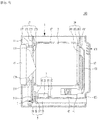
- FIG. 1 illustrates an example laundry treating apparatus 100.
- the laundry treating apparatus 100 includes a cabinet 1 defining an external appearance of the laundry treating apparatus, an accommodation space provided in the cabinet 1 to accommodate laundry, a supply portion 4 to supply air to the accommodation space, and a discharge portion 5 to discharge air in the accommodation space from the cabinet 1.
- the cabinet 1 may include a front panel 11 provided with an introduction port 111 for introduction and retrieval of laundry, and a rear panel 13 provided with a cabinet inlet port 131 allowing the interior of the cabinet 1 to communicate with the exterior of the cabinet 1.
- the front panel 11 is provided with a door 15 to open and close the introduction port 111. Accordingly, a user may introduce the laundry into or retrieve the same from the accommodation space through the door 15 and the introduction port 111.
- the rear panel 13 is arranged to face the front panel 11 of the cabinet 1 provided with the door 15.
- the cabinet inlet port 131 allows air outside of the cabinet 1 to flow into the cabinet.
- the cabinet inlet port 131 is a flow channel (e.g., a cabinet flow channel) allowing air outside of the cabinet to flow into the cabinet therethrough.
- a flow channel e.g., a cabinet flow channel
- the cabinet inlet port 131 may be provided with a plurality of panel through holes 1311 formed to penetrate the rear panel 13 in the width direction of the cabinet 1 (the direction of Z axis), and a flange 1313 extending from the lower surface of each of the panel through holes toward the interior of the cabinet 1 to be inclined.
- the flanges 1313 reduce (e.g., prevent) water outside of the cabinet 1 from flowing into the cabinet 1 through the panel through holes 1311. Accordingly, when the indoor space where the laundry treating apparatus 100 is installed is cleaned, it may be possible to minimize introduction of water into the cabinet 1.
- the rear panel 13 may be further provided with a cabinet discharge port 133 to discharge air moving through the discharge portion 5 from the cabinet 1.
- the accommodation space may be provided with a drum 2 rotatably arranged in the cabinet 1.
- the drum 2 may be formed in a cylindrical shape having an open front and open back.
- the cabinet 1 may be further provided therein with a front support 17 and a rear support 19 which support the drum 2 such that the drum 2 is rotatable.
- the front support 17 may be provided with a support body 171 fixed to the interior of the cabinet 1, a body through hole 173 provided to penetrate the support body 171, and a front flange 175 provided to the support body 171 to support the front of the drum 2.
- the body through hole 173 is arranged to communicate with the introduction port 111, and accordingly the laundry introduced through the introduction port 111 may be moved into the drum 2 through the body through hole 173.
- the support body 171 may be provided with a guide duct 177 having a cylindrical shape and extending toward the door 15.
- the guide duct 177 may be arranged to connect the front panel 11 to the support body 171 to surround the circumferential surface of the body through hole 173 and the circumferential surface of the introduction port 111.
- the front flange 175 may be formed to protrude from the surface of the support body 171 toward the drum 2, along the circumferential surface of the body through hole 173.
- the inner circumferential surface of the front of the drum 2 is rotatably supported by the outer circumferential surface of the front flange 175.
- the front support 17 is further provided with a discharge portion connection hole 179 coupled to the discharge portion 5, which will be described in more detail later.
- the discharge portion connection hole 179 is arranged to penetrate the guide duct 177.
- the discharge portion connection hole 179 allows the interior of the drum 2 to communicate with the exterior of the drum 2 therethrough.
- the rear support 19 may be provided with a support body 191 fixed to the interior of the cabinet 1, and a rear flange 193 provided to the support body 191 to support the back of the drum 2 such that the drum 2 is rotatable.
- the rear support 19 is further provided with a supply portion connection hole 195 coupled to the supply portion 4, which will be described in more detail later.
- the supply portion connection hole 195 is formed to penetrate the support body 191.
- the supply portion connection hole 195 allows the interior of the drum 2 to communicate with the exterior of the drum 2.
- the accommodation space may be provided with a tub arranged in the cabinet 1 to contain washing water, and a drum 2 rotatably coupled to the interior of the tub.
- the front support and the rear support may be omitted.
- the body through hole 173, the guide duct 177 and the discharge portion connection hole 179 are provided to the front of the tub, which is cylindrically shaped.
- the supply portion connection hole 195 may be provided to the outer circumferential surface of the tub, and the drum 2 may be rotatably supported in the tub by a rotating shaft that penetrates the back of the tub.
- the circumferential surface of the drum may be provided with a plurality of through holes allowing the tub to communicate with the interior of the drum therethrough.
- laundry treating apparatus 100 which only functions to dry laundry, as an example.
- features of this example may be applied to other types of laundry treating apparatus.
- the drum 2 is rotated by a drive unit 3.
- the drive unit 3 may include a drum motor 31 provided in the cabinet 1, a first rotating shaft 33 and a second rotating shaft 35, which are rotated by the drum motor 31, and a belt 37 to connect the circumferential surface of the drum 2 to the first rotating shaft 33.
- the second rotating shaft 35 is connected to an exhaust fan 57 through a fan housing 55 provided to the discharge portion 5. Accordingly, in the illustrated example, the drum 2 and the exhaust fan 57 may be rotated at the same time using one drum motor 31.
- the supply portion 4 is a supply flow channel through which air (e.g., hot air or unheated air) is supplied to the drum 2. Accordingly, the supply portion 4 may be composed of a supply duct 43 through which air is supplied to the drum 2.
- air e.g., hot air or unheated air
- the supply duct 43 may be arranged to supply air from inside the cabinet 1 into the drum 2, or to supply air outside of the cabinet 1 to the drum 2.
- the supply portion 4 may include a heating duct 41 provided with a heater 45 to heat air and a supply duct 43 to guide the air discharged from the heating duct 41 to the drum 2.
- heated air e.g., hot air
- the supply portion 4 may include a heating duct 41 provided with a heater 45 to heat air and a supply duct 43 to guide the air discharged from the heating duct 41 to the drum 2.
- the heating duct 41 may be formed in the shape of a column having open opposite sides facing each other and positioned in the cabinet 1.
- the supply duct 43 may include a duct body 431 to connect the heating duct 41 with the supply portion connection hole 195.
- the duct body 431 may extend from the heating duct 41 along the height of the cabinet 1 (e.g., the height of the drum 2).
- the duct body 431 coupled to the supply portion connection hole 195 may be provided with a mount surface 435 (inclined surface) parallel with or inclined toward the bottom surface of the cabinet 1.
- the discharge portion 5 is a discharge flow channel through which air in the drum 2 is discharged from the cabinet 1 (a discharge flow channel through which air in the drum 2 is discharged to an outside of the cabinet 1). Accordingly, the discharge portion 5 may include a connection duct 51 through which the air in the drum 2 is discharged, and an exhaust duct 53 to guide the air introduced into the connection duct 51 to the outside of the cabinet 1.
- connection duct 51 and the exhaust duct 53 are connected to each other through the fan housing 55.
- the fan housing 55 is provided with an exhaust fan 57 to move the air in the drum 2 into the connection duct 51.
- connection duct 51 includes a duct inlet port 511 and a duct discharge port 513.
- the duct inlet port 511 is coupled to the discharge portion connection hole 179 provided in the front support 17.
- the fan housing 55 provides a space in which the exhaust fan 57 is rotatable and connects the duct discharge port 513 to the exhaust duct 53.
- the air in the drum 2 may be introduced into the connection duct 51 through the discharge portion connection hole 179 and the duct inlet port 511, and the air in the connection duct 51 may be moved to the exhaust duct 53 through the duct discharge port 513 and the fan housing 55.
- the pressure in the drum 2 is lowered, and therefore the air in the cabinet 1 may be moved into the drum 2 through the supply portion 4.
- the drum 2, the discharge flow channels 51 and 53, and the supply flow channels 41 and 43 are connected to each other to form a single flow channel (one flow channel unit). Accordingly, when the air in the drum 2 is discharged from the cabinet 1 through the exhaust fan 57, air flow is created between the flow channel unit and the cabinet flow channel, and thus air may be continuously supplied to the drum 2. Therefore, the laundry treating apparatus according to the illustrated example does not supply air to the drum 2 unless the exhaust fan 57 operates.
- the laundry treating apparatus 100 configured as above may encounter the following problems when fire breaks out in the laundry stored in the drum 2.
- the laundry treating apparatus 100 further includes a shutoff portion 9 ( FIG. 7 ) to prevent explosion by blocking supply of air to the drum 2 (naturally extinguishing flames) in addition to a pressure reduction portion 7 (although not shown in FIG. 7 ) to prevent discharge of flames from the drum 2 to the outside of the cabinet 1 due to pressure produced when explosion occurs in the drum 2.
- the pressure reduction portion 7 discharges the air in the drum 2 not from the cabinet 1 but into the cabinet 1 such that flames are prevented from being discharged from the cabinet 1.
- the pressure reduction portion 7 is provided to prevent the flames from being discharged from the cabinet 1 due to explosion by discharging the air in the drum 2 into the cabinet 1 (by decreasing the pressure in the drum) in the case that explosion occurs in the drum 2 in spite of presence of the shutoff portion 9.
- the pressure reduction portion 7 may be provided in the upper stream of the flow channel unit, which guides air to the exhaust fan 57, to discharge the air in the drum 2 into the cabinet 1 when pressure in the drum 2 is equal to or higher than a predetermined reference pressure.
- the pressure reduction portion 7 may be provided with an opening/closing device 71 and 73 (a supply portion opening/closing device) provided to the supply portion 4 to move the air in the drum 2 into the cabinet 1 when the pressure in the drum 2 is equal to or higher than a predetermined reference pressure.
- an opening/closing device 71 and 73 a supply portion opening/closing device
- the reference pressure may be set to a pressure in the drum expected to be produced when explosion occurs in the drum 2 (an experimental value).
- the reference pressure may be set to (or slightly lower than) a pressure which releases fastening between the door 15 and the cabinet 1 (e.g., a pressure capable of forcing the door open).
- the reference pressure may be set to a pressure which overcomes the force by which the door 15 is fastened to the cabinet 1. This is because the door 15, among the structures allowing the interior of the drum to communicate with the exterior of the drum therethrough (e.g., the structures allowing the flow channel unit to communicate with the exterior of the cabinet therethrough), is openable with the smallest force.
- the supply portion opening/closing device may be provided with a supply duct exhaust hole 71 provided to the supply duct 43 to allow the interior of a supply duct 43 to communicate with the interior of the cabinet 1 therethrough, and a supply duct door (a supply duct flap) 73 rotatably provided to the supply duct 41 to open the supply duct exhaust hole 71 when the pressure in the drum 2 is equal to or higher than the reference pressure.
- a supply duct exhaust hole 71 provided to the supply duct 43 to allow the interior of a supply duct 43 to communicate with the interior of the cabinet 1 therethrough
- a supply duct door (a supply duct flap) 73 rotatably provided to the supply duct 41 to open the supply duct exhaust hole 71 when the pressure in the drum 2 is equal to or higher than the reference pressure.
- the self-weight of the supply duct door 73 may be equal to or lower than the force that fastens the door 15 and the cabinet 1 to each other. This is intended to cause the supply duct door 73 to be opened earlier than the door 15 when explosion occurs in the drum 2.
- the supply duct door 73 may be arranged such that the supply duct exhaust hole 71 is closed by self-weight of the supply duct door 73.
- the supply duct door 73 may be arranged such that the supply duct exhaust hole 71 is opened by a controlling device, such as a controller.
- closure based on self-weight may be used in addition or as an alternative to closure by a controller because electronic components equipped in the laundry treating apparatus 100 may malfunction when fire or explosion breaks out in the drum 2.
- the supply portion opening/closing device 71 and 73 may be provided at any location on the supply portion 4.
- the supply portion opening/closing device 71 and 73 may be provided at the supply duct 43 adjacent to the supply portion connection hole 195. This location is intended to allow the air in the drum 2 to be discharged into the cabinet 1 when explosion occurs in the drum 2.
- the supply portion opening/closing device 71 and 73 may be provided on the surface of the duct body 431 facing the rear panel 13, or on the mount surface 435 provided at the upper portion of the duct body 431.
- the supply portion opening/closing device 71 and 73 is provided on the surface of the duct body 431 facing the rear panel 13, a space is provided to prevent the rear panel 13 and the supply duct door 73 from interfering with each other when the supply duct door 73 is opened between the duct body 431 and the rear panel 13.
- the supply duct exhaust hole 71 may not be completely sealed solely by the self-weight of the supply duct door 73, and noise may be caused during operation of the laundry treating apparatus.
- the length of the laundry treating apparatus 100 in the depth direction (i.e., the X-axis direction) may be minimized and the supply portion opening/closing device 71 and 73 may be provided on the mount surface 435 to seal the supply duct exhaust hole 71.
- the mount surface 435 may be arranged parallel with the bottom surface of the cabinet 1 or arranged inclined at a predetermined inclination angle from the supply portion connection hole 195 toward the bottom surface of the cabinet 1.
- the supply duct door 73 When the mount surface 435 is arranged inclined with respect to the bottom surface of the cabinet 1, rather than parallel with the bottom surface of the cabinet 1, the supply duct door 73 may be promptly opened and the supply duct exhaust hole 71 may be closed by self-weight of the supply duct door 73 when explosion occurs in the drum 2.
- the supply duct exhaust hole 71 of the supply portion opening/closing device is arranged to penetrate the mount surface 435 to allow the interior of the duct body 431 to communicate with the interior of the cabinet 1 therethrough.
- the supply duct door 73 may be provided with a body 731 (first body) to open and close the supply duct exhaust hole 71, a body support 733 (first body support) provided on the mount surface 435, and a rotating shaft 735 to couple the first body 731 to the first body support 733 such that the first body 731 is rotatable.
- the laundry treating apparatus 100 normally operates (e.g., when the exhaust fan 57 normally operates), a negative pressure is formed in the supply duct 43, and therefore the supply duct door 73 will not open the supply duct exhaust hole 71 so long as explosion does not occur in the drum 2 (e.g., so long as the pressure in the drum does not become equal to or higher than a reference pressure).
- the cabinet inlet port 131 is arranged in the width direction of the cabinet (the Z-axis direction) such that the cabinet inlet port 131 penetrates the projection plane M of the supply duct exhaust hole 71 projected on the rear panel 13, flames produced by explosion in the drum 2 may be disposed from the cabinet 1 via the supply duct exhaust hole 71 and the cabinet inlet port 131.
- the cabinet inlet port 131 may be arranged not to interfere with the projection plane M of the supply duct exhaust hole 71 projected on the rear panel 13.
- the cabinet inlet port 131 may be provided to the rear panel 13 in an inclined manner L to be parallel with the lower portion of the projection plane M. In this case, however, it is possible that water outside of the cabinet is introduced into the cabinet through the cabinet inlet port 131.
- the cabinet inlet port 131 may be arranged on the rear panel 13 to be parallel with the bottom surface of the cabinet 1 but not to interfere with the projection plane M, as shown in FIG. 3(b) .
- the supply portion opening/closing device 71 and 73 is provided to the supply portion 4. This is simply an example, and the present disclosure is not limited thereto.
- the supply portion opening/closing device 71 and 73 may be provided at various locations so long as the air in the drum 2 is allowed to be discharged into the cabinet 1 when the pressure in the drum 2 is equal to or higher than the reference pressure.
- the supply portion opening/closing device 71 may be provided on the circumferential surface A (see FIG. 1 ) of the drum 2, or on at least one of surfaces B of the front support 17 and the rear support 19 (see FIG. 1 ).
- the laundry treating apparatus 100 configured as described above may prevent flames in the drum 2 from being discharged from the cabinet 1 when pressure in the drum 2 becomes equal to or higher than the reference pressure due to explosion, as the supply duct door 73 opens the supply duct exhaust hole 71 before the door 15 opens the introduction port 111.
- FIG. 4 illustrates an example laundry treating apparatus 100.
- the pressure reduction portion 7 is provided with a discharge portion opening/closing device arranged at the discharge portion 5 to discharge the air in the drum into the cabinet 1 when the pressure in the drum is equal or higher than the reference pressure.
- the discharge portion opening/closing device may be provided at any location at the discharge portion 5 so long as the air introduced from the drum 2 into the discharge portion 5 is supplied into the cabinet 1.
- the discharge portion opening/closing device may be provided to the connection duct 51, as shown in FIG. 5 .
- connection duct 51 is closest to the drum 2. Accordingly, in the case that the discharge portion opening/closing device 72 and 74 is provided to the connection duct 51, the pressure in the drum 2 may be quickly lowered when explosion occurs in the drum 2.
- the discharge portion opening/closing device may be provided with a connection duct exhaust hole 72 arranged to penetrate the connection duct 51, and a connection duct door (a connection duct flap) 74 rotatably arranged at the connection duct to open and close the connection duct exhaust hole 72.
- connection duct door 74 may be provided with a body 741 (second body) to close the connection duct exhaust hole 72 due to gravity, a second body support 745 fixed to the connection duct 51, and a rotating shaft 747 to connect the second body 741 with the second body support 745.
- the self-weight of the connection duct door 74 (the self-weight of the second body 741) may be less than the force by which the door 15 and the cabinet 1 are fastened to each other.
- connection duct door 74 does not open the connection duct exhaust hole 72, unless the pressure in the drum 2 becomes equal to or higher than a reference pressure.
- the discharge portion opening/closing device may be configured as shown in FIG. 6 .
- the discharge portion opening/closing device is configured such that a guider 749 provided to the second body support 745 guides movement of the second body 741.
- the second body support 745 may be provided with a fixed end fixed to the connection duct 51, and an extended end extending from the fixed end toward the center of the second body 741 and spaced at a predetermined distance from the second body 741.
- a body penetrating hole 743 to penetrate the center of the second body 741 may be provided in the second body 741, and the guider 749 may extend from the extended end toward the connection duct exhaust hole 72 to be inserted into the body penetrating hole 743.
- the configuration of the discharge portion opening/closing device 72 and 74 described above and shown in FIG. 6 may also be applied to the supply portion opening/closing device 71 and 73.
- the discharge portion opening/closing device 72 and 74 shown in FIGs. 5 and 6 is adapted to lower the pressure in the drum 2, but it may not fulfill the purpose in the case that explosion occurs in the drum 2 with the laundry clogging the discharge portion connection hole 179 (e.g., with the duct inlet port 511 closed).
- the discharge portion opening/closing device 72 and 74 may be provided, along with the opening/closing device 71 and 73, to the supply portion 4.
- the shutoff portion 9 is provided to block supply of air into the drum 2 when fire breaks out in the drum 2 such that flames in the drum 2 are naturally extinguished.
- shutoff portion 9 prevents flow of air between the supply flow channels 41 and 43 and the cabinet flow channel 131, but allows flow of air between the discharge channel 53 that communicates with the outside of the cabinet 1 and the cabinet flow channel 131. Thereby, when fire breaks out in the drum 2, likelihood of explosion of the drum 2 may be reduced.
- the shutoff portion 9 may be provided at any location in the laundry treating apparatus 100 so long as it is arranged in the down stream of the flow channel unit 41, 43, 2, 51 and 53 which guides the air having passed through the exhaust fan 57 to the outside of the cabinet 1.
- FIG. 7 shows an example of the shutoff portion 9 provided at the discharge portion 5.
- the shutoff portion 9 may be provided with an exhaust duct penetrating hole 91 arranged to penetrate the exhaust duct 53 to allow the interior of the exhaust duct 53 to communicate with the interior of the cabinet 1, and a penetrating hole door (a penetrating hole flap) 93 rotatably provided to the exhaust duct 53 to selectively open the exhaust duct penetrating hole 91 and the exhaust duct 53 (e.g., to open one of the exhaust duct penetrating hole and the exhaust duct).
- a penetrating hole door a penetrating hole flap
- the penetrating hole door 93 may be provided with a body rotation shaft 933 provided to the exhaust duct 53, and a body 931 to selectively open the exhaust duct penetrating hole 91 and the exhaust duct 53 by rotating about the body rotation shaft 933 in the exhaust duct 53.
- the body 931 may be configured such that the exhaust duct penetrating hole 91 is opened and closed by a controller. Also, the body 931 may be configured such that the exhaust duct 53 is closed by the self-weight of the body 931 and the exhaust duct penetrating hole 91 is closed by the exhaust fan 57.
- This configuration is intended to enable the shutoff portion 9 to operate in the case that electronic devices malfunction due to fire breaking out in the drum 2.
- the exhaust duct 53 is connected to a flow channel arranged through the wall of the house to discharge air discharged from the drum 2 to the outdoors during drying of the laundry. Therefore, depending on a change in the outdoor atmospheric pressure, the outdoor air may be supplied into the drum 2 through the exhaust duct 53, or the air in the drum 2 may be discharged to the outdoor through the exhaust duct 5.
- air may be supplied into the drum 2 through the exhaust duct 53, or air may be discharged from the drum 2.
- the shutoff portion 9 is intended to prevent explosion in the drum 2 due to supply of air into the drum 2 when operation of the exhaust fan 57 has been stopped.
- the air in the cabinet 1 will be discharged from the cabinet 1 through the exhaust duct penetrating hole 91 since the atmospheric pressure outside of the cabinet 1 is low (e.g., flow of air between the discharge flow channels 51, 53 and 55 and the cabinet flow channel 131 occurs).
- the shutoff portion 9 may quickly extinguish the flames in the drum 2 when the atmospheric pressure outside of the cabinet 1 is low.
- the exhaust duct penetrating hole 91 is opened and the exhaust duct 53 is closed by the penetrating hole door 93. Accordingly, the air outside of the cabinet 1 is not supplied into the drum 2 through the exhaust duct 53 even if the atmospheric pressure outside of the cabinet 1 is high.
- the air outside of the cabinet 1 may be introduced into the cabinet 1 through the exhaust duct 53 and the exhaust duct penetrating hole 91 since the atmospheric pressure outside of the cabinet 1 is high.
- the shutoff portion 9 may cause the flames in the drum 2 to be naturally extinguished by shutting off air supplied into the drum 2, even when the atmospheric pressure outside of the laundry treating apparatus 100 is high.
- FIG. 9 illustrates an example laundry treating apparatus 100 provided with both the pressure reduction portion 7 and the shutoff portion 9.
- the pressure reduction portion 7 is provided with an opening/closing device 71 and 73 (a supply portion opening/closing device) provided to the supply portion 4 and a discharge portion opening/closing device 72 and 74 provided to the discharge portion 5.
- the pressure reduction portion 7 may also be only provided with one of the opening/closing device 71 and 73 (a supply portion opening/closing device) provided to the supply portion 4 and the discharge portion opening/closing device 72 and 74 provided to the discharge portion 5.
- the opening/closing device 71 and 73 and discharge portion opening/closing device 72 and 74 are adapted to discharge the air in the drum 2 into the cabinet 1 when the pressure in the drum 2 is equal to or higher than a reference pressure.
- the shutoff portion 9 is provided to the exhaust duct 53 to open the exhaust duct penetrating hole 91 and close the exhaust duct 53 when operation of the exhaust fan 57 is stopped.
- a laundry treating apparatus may allow flames in the accommodation space containing laundry to be naturally extinguished when fire breaks out in the accommodation space.
- a laundry treating apparatus also may prevent explosion from occurring in the accommodation space containing laundry due to flammable gas when fire breaks out in the accommodation space.
- a laundry treating apparatus may prevent flames from being discharged from the accommodation space containing laundry when explosion occurs in the accommodation space.
Landscapes
- Engineering & Computer Science (AREA)
- Textile Engineering (AREA)
- Detail Structures Of Washing Machines And Dryers (AREA)
- Accessory Of Washing/Drying Machine, Commercial Washing/Drying Machine, Other Washing/Drying Machine (AREA)
- Control Of Washing Machine And Dryer (AREA)
Applications Claiming Priority (1)
| Application Number | Priority Date | Filing Date | Title |
|---|---|---|---|
| KR1020130021184A KR102047697B1 (ko) | 2013-02-27 | 2013-02-27 | 의류처리장치 |
Publications (2)
| Publication Number | Publication Date |
|---|---|
| EP2772580A1 EP2772580A1 (en) | 2014-09-03 |
| EP2772580B1 true EP2772580B1 (en) | 2019-05-01 |
Family
ID=49885136
Family Applications (1)
| Application Number | Title | Priority Date | Filing Date |
|---|---|---|---|
| EP14150081.9A Active EP2772580B1 (en) | 2013-02-27 | 2014-01-02 | Laundry treating apparatus |
Country Status (8)
| Country | Link |
|---|---|
| EP (1) | EP2772580B1 (pt) |
| JP (1) | JP5801863B2 (pt) |
| KR (1) | KR102047697B1 (pt) |
| CN (1) | CN104005210B (pt) |
| AU (1) | AU2014200221B2 (pt) |
| BR (1) | BR102013029603A8 (pt) |
| IN (1) | IN2013CH05085A (pt) |
| RU (1) | RU2568795C2 (pt) |
Families Citing this family (3)
| Publication number | Priority date | Publication date | Assignee | Title |
|---|---|---|---|---|
| KR101673923B1 (ko) * | 2016-04-21 | 2016-11-08 | 에이스티엔에스(주) | 원적외선을 이용한 섬유제품의 세탁물용 대용량 건조 장치 |
| KR20210020403A (ko) * | 2019-08-14 | 2021-02-24 | 엘지전자 주식회사 | 의류 처리장치 |
| JP2021182981A (ja) * | 2020-05-21 | 2021-12-02 | パナソニックIpマネジメント株式会社 | 衣類乾燥機 |
Citations (2)
| Publication number | Priority date | Publication date | Assignee | Title |
|---|---|---|---|---|
| CN2491478Y (zh) * | 2001-07-18 | 2002-05-15 | 伟裕机械板金工业股份有限公司 | 可烘干干洗衣物并回收有机溶剂的烘干机 |
| KR100856575B1 (ko) * | 2007-12-24 | 2008-09-05 | 주식회사 대일 | 의류건조기 본체용 방폭장치 |
Family Cites Families (13)
| Publication number | Priority date | Publication date | Assignee | Title |
|---|---|---|---|---|
| US4262430A (en) * | 1979-11-15 | 1981-04-21 | Hoyt Manufacturing Corporation | Combination solvent reclaimer and dryer |
| JPS6063198U (ja) * | 1983-10-05 | 1985-05-02 | 松下電器産業株式会社 | ガス式衣類乾燥機 |
| JPS62151898U (pt) * | 1986-03-18 | 1987-09-26 | ||
| JPH01262895A (ja) * | 1988-04-13 | 1989-10-19 | Sanyo Electric Co Ltd | 衣類乾燥機 |
| US6189228B1 (en) * | 1999-07-21 | 2001-02-20 | Lyle Schuette | Support/heat valve for dryer |
| JP2002081858A (ja) * | 2000-09-01 | 2002-03-22 | Toto Ltd | 乾燥装置 |
| JP4121822B2 (ja) * | 2002-10-04 | 2008-07-23 | 三洋電機株式会社 | ドライクリーニング装置 |
| EP1589144B1 (en) * | 2004-04-21 | 2009-04-15 | Samsung Electronics Co., Ltd. | Clothes drying machine |
| KR100825253B1 (ko) * | 2007-07-10 | 2008-04-25 | 이진식 | 유기용매 사용기기의 폭발방지장치 |
| KR101430457B1 (ko) * | 2007-11-12 | 2014-08-18 | 엘지전자 주식회사 | 의류처리장치 |
| KR20100138427A (ko) * | 2009-06-25 | 2010-12-31 | 엘지전자 주식회사 | 의류 처리장치 |
| AU2011239089B2 (en) * | 2010-04-09 | 2014-03-27 | Lg Electronics Inc. | Clothes treatment apparatus and control method thereof |
| JP5511738B2 (ja) * | 2011-06-20 | 2014-06-04 | リンナイ株式会社 | イオン供給ユニット |
-
2013
- 2013-02-27 KR KR1020130021184A patent/KR102047697B1/ko active IP Right Grant
- 2013-11-11 IN IN5085CH2013 patent/IN2013CH05085A/en unknown
- 2013-11-18 RU RU2013151170/12A patent/RU2568795C2/ru not_active IP Right Cessation
- 2013-11-18 BR BR102013029603A patent/BR102013029603A8/pt not_active IP Right Cessation
- 2013-12-04 JP JP2013250909A patent/JP5801863B2/ja not_active Expired - Fee Related
- 2013-12-05 CN CN201310651749.8A patent/CN104005210B/zh not_active Expired - Fee Related
-
2014
- 2014-01-02 EP EP14150081.9A patent/EP2772580B1/en active Active
- 2014-01-14 AU AU2014200221A patent/AU2014200221B2/en not_active Ceased
Patent Citations (2)
| Publication number | Priority date | Publication date | Assignee | Title |
|---|---|---|---|---|
| CN2491478Y (zh) * | 2001-07-18 | 2002-05-15 | 伟裕机械板金工业股份有限公司 | 可烘干干洗衣物并回收有机溶剂的烘干机 |
| KR100856575B1 (ko) * | 2007-12-24 | 2008-09-05 | 주식회사 대일 | 의류건조기 본체용 방폭장치 |
Also Published As
| Publication number | Publication date |
|---|---|
| CN104005210B (zh) | 2016-06-29 |
| KR102047697B1 (ko) | 2019-11-22 |
| AU2014200221B2 (en) | 2015-09-24 |
| IN2013CH05085A (pt) | 2015-07-31 |
| KR20140106910A (ko) | 2014-09-04 |
| RU2013151170A (ru) | 2015-05-27 |
| JP5801863B2 (ja) | 2015-10-28 |
| AU2014200221A1 (en) | 2014-09-11 |
| BR102013029603A2 (pt) | 2016-04-05 |
| EP2772580A1 (en) | 2014-09-03 |
| BR102013029603A8 (pt) | 2021-04-13 |
| CN104005210A (zh) | 2014-08-27 |
| RU2568795C2 (ru) | 2015-11-20 |
| JP2014161727A (ja) | 2014-09-08 |
Similar Documents
| Publication | Publication Date | Title |
|---|---|---|
| US9568244B2 (en) | Laundry treating apparatus | |
| EP2772580B1 (en) | Laundry treating apparatus | |
| EP3324815B1 (en) | Dishwasher | |
| KR102052373B1 (ko) | 의류처리장치 | |
| US9562314B2 (en) | Laundry treating apparatus | |
| CA2629493A1 (en) | Clothes dryer with louvre cover | |
| EP2772581B1 (en) | Laundry treating apparatus | |
| US20150168064A1 (en) | Laundry dryer with emergency closing ventilation system | |
| KR100646885B1 (ko) | 드럼 세탁기의 건조 덕트 | |
| CN207109398U (zh) | 干衣机 | |
| KR20060103581A (ko) | 건조기의 소화장치 | |
| KR20150118859A (ko) | 건조기 | |
| KR20200030387A (ko) | 의류 관리기 | |
| JP2008104492A (ja) | 衣類乾燥機 | |
| JP2007283091A (ja) | 回転ドラム式乾燥機 | |
| KR101848668B1 (ko) | 의류처리장치 | |
| KR20140107818A (ko) | 의류처리장치 | |
| US20210113867A1 (en) | Dryer appliance having a fire extinguishing system equpped with a multiway inlet valve | |
| KR20070081856A (ko) | 드럼식 의류건조기의 컨트롤부 | |
| KR100823320B1 (ko) | 의류건조기용 안전덕트 | |
| KR102047699B1 (ko) | 의류처리장치 | |
| KR101241874B1 (ko) | 드럼식 의류건조기의 컨트롤부 | |
| KR20220014047A (ko) | 소방용품 건조 장치 | |
| CN110857520A (zh) | 衣物干燥机 |
Legal Events
| Date | Code | Title | Description |
|---|---|---|---|
| PUAI | Public reference made under article 153(3) epc to a published international application that has entered the european phase |
Free format text: ORIGINAL CODE: 0009012 |
|
| 17P | Request for examination filed |
Effective date: 20140331 |
|
| AK | Designated contracting states |
Kind code of ref document: A1 Designated state(s): AL AT BE BG CH CY CZ DE DK EE ES FI FR GB GR HR HU IE IS IT LI LT LU LV MC MK MT NL NO PL PT RO RS SE SI SK SM TR |
|
| AX | Request for extension of the european patent |
Extension state: BA ME |
|
| STAA | Information on the status of an ep patent application or granted ep patent |
Free format text: STATUS: EXAMINATION IS IN PROGRESS |
|
| 17Q | First examination report despatched |
Effective date: 20180228 |
|
| GRAP | Despatch of communication of intention to grant a patent |
Free format text: ORIGINAL CODE: EPIDOSNIGR1 |
|
| STAA | Information on the status of an ep patent application or granted ep patent |
Free format text: STATUS: GRANT OF PATENT IS INTENDED |
|
| INTG | Intention to grant announced |
Effective date: 20181204 |
|
| RAP1 | Party data changed (applicant data changed or rights of an application transferred) |
Owner name: LG ELECTRONICS INC. |
|
| GRAS | Grant fee paid |
Free format text: ORIGINAL CODE: EPIDOSNIGR3 |
|
| GRAA | (expected) grant |
Free format text: ORIGINAL CODE: 0009210 |
|
| STAA | Information on the status of an ep patent application or granted ep patent |
Free format text: STATUS: THE PATENT HAS BEEN GRANTED |
|
| AK | Designated contracting states |
Kind code of ref document: B1 Designated state(s): AL AT BE BG CH CY CZ DE DK EE ES FI FR GB GR HR HU IE IS IT LI LT LU LV MC MK MT NL NO PL PT RO RS SE SI SK SM TR |
|
| REG | Reference to a national code |
Ref country code: GB Ref legal event code: FG4D |
|
| REG | Reference to a national code |
Ref country code: CH Ref legal event code: EP Ref country code: AT Ref legal event code: REF Ref document number: 1127021 Country of ref document: AT Kind code of ref document: T Effective date: 20190515 |
|
| REG | Reference to a national code |
Ref country code: DE Ref legal event code: R096 Ref document number: 602014045592 Country of ref document: DE |
|
| REG | Reference to a national code |
Ref country code: IE Ref legal event code: FG4D |
|
| REG | Reference to a national code |
Ref country code: NL Ref legal event code: MP Effective date: 20190501 |
|
| REG | Reference to a national code |
Ref country code: LT Ref legal event code: MG4D |
|
| PG25 | Lapsed in a contracting state [announced via postgrant information from national office to epo] |
Ref country code: NO Free format text: LAPSE BECAUSE OF FAILURE TO SUBMIT A TRANSLATION OF THE DESCRIPTION OR TO PAY THE FEE WITHIN THE PRESCRIBED TIME-LIMIT Effective date: 20190801 Ref country code: FI Free format text: LAPSE BECAUSE OF FAILURE TO SUBMIT A TRANSLATION OF THE DESCRIPTION OR TO PAY THE FEE WITHIN THE PRESCRIBED TIME-LIMIT Effective date: 20190501 Ref country code: LT Free format text: LAPSE BECAUSE OF FAILURE TO SUBMIT A TRANSLATION OF THE DESCRIPTION OR TO PAY THE FEE WITHIN THE PRESCRIBED TIME-LIMIT Effective date: 20190501 Ref country code: HR Free format text: LAPSE BECAUSE OF FAILURE TO SUBMIT A TRANSLATION OF THE DESCRIPTION OR TO PAY THE FEE WITHIN THE PRESCRIBED TIME-LIMIT Effective date: 20190501 Ref country code: SE Free format text: LAPSE BECAUSE OF FAILURE TO SUBMIT A TRANSLATION OF THE DESCRIPTION OR TO PAY THE FEE WITHIN THE PRESCRIBED TIME-LIMIT Effective date: 20190501 Ref country code: PT Free format text: LAPSE BECAUSE OF FAILURE TO SUBMIT A TRANSLATION OF THE DESCRIPTION OR TO PAY THE FEE WITHIN THE PRESCRIBED TIME-LIMIT Effective date: 20190901 Ref country code: AL Free format text: LAPSE BECAUSE OF FAILURE TO SUBMIT A TRANSLATION OF THE DESCRIPTION OR TO PAY THE FEE WITHIN THE PRESCRIBED TIME-LIMIT Effective date: 20190501 Ref country code: ES Free format text: LAPSE BECAUSE OF FAILURE TO SUBMIT A TRANSLATION OF THE DESCRIPTION OR TO PAY THE FEE WITHIN THE PRESCRIBED TIME-LIMIT Effective date: 20190501 Ref country code: NL Free format text: LAPSE BECAUSE OF FAILURE TO SUBMIT A TRANSLATION OF THE DESCRIPTION OR TO PAY THE FEE WITHIN THE PRESCRIBED TIME-LIMIT Effective date: 20190501 |
|
| PG25 | Lapsed in a contracting state [announced via postgrant information from national office to epo] |
Ref country code: BG Free format text: LAPSE BECAUSE OF FAILURE TO SUBMIT A TRANSLATION OF THE DESCRIPTION OR TO PAY THE FEE WITHIN THE PRESCRIBED TIME-LIMIT Effective date: 20190801 Ref country code: RS Free format text: LAPSE BECAUSE OF FAILURE TO SUBMIT A TRANSLATION OF THE DESCRIPTION OR TO PAY THE FEE WITHIN THE PRESCRIBED TIME-LIMIT Effective date: 20190501 Ref country code: LV Free format text: LAPSE BECAUSE OF FAILURE TO SUBMIT A TRANSLATION OF THE DESCRIPTION OR TO PAY THE FEE WITHIN THE PRESCRIBED TIME-LIMIT Effective date: 20190501 |
|
| REG | Reference to a national code |
Ref country code: AT Ref legal event code: MK05 Ref document number: 1127021 Country of ref document: AT Kind code of ref document: T Effective date: 20190501 |
|
| PG25 | Lapsed in a contracting state [announced via postgrant information from national office to epo] |
Ref country code: IS Free format text: LAPSE BECAUSE OF FAILURE TO SUBMIT A TRANSLATION OF THE DESCRIPTION OR TO PAY THE FEE WITHIN THE PRESCRIBED TIME-LIMIT Effective date: 20190901 |
|
| PG25 | Lapsed in a contracting state [announced via postgrant information from national office to epo] |
Ref country code: SK Free format text: LAPSE BECAUSE OF FAILURE TO SUBMIT A TRANSLATION OF THE DESCRIPTION OR TO PAY THE FEE WITHIN THE PRESCRIBED TIME-LIMIT Effective date: 20190501 Ref country code: EE Free format text: LAPSE BECAUSE OF FAILURE TO SUBMIT A TRANSLATION OF THE DESCRIPTION OR TO PAY THE FEE WITHIN THE PRESCRIBED TIME-LIMIT Effective date: 20190501 Ref country code: DK Free format text: LAPSE BECAUSE OF FAILURE TO SUBMIT A TRANSLATION OF THE DESCRIPTION OR TO PAY THE FEE WITHIN THE PRESCRIBED TIME-LIMIT Effective date: 20190501 Ref country code: AT Free format text: LAPSE BECAUSE OF FAILURE TO SUBMIT A TRANSLATION OF THE DESCRIPTION OR TO PAY THE FEE WITHIN THE PRESCRIBED TIME-LIMIT Effective date: 20190501 Ref country code: RO Free format text: LAPSE BECAUSE OF FAILURE TO SUBMIT A TRANSLATION OF THE DESCRIPTION OR TO PAY THE FEE WITHIN THE PRESCRIBED TIME-LIMIT Effective date: 20190501 Ref country code: CZ Free format text: LAPSE BECAUSE OF FAILURE TO SUBMIT A TRANSLATION OF THE DESCRIPTION OR TO PAY THE FEE WITHIN THE PRESCRIBED TIME-LIMIT Effective date: 20190501 |
|
| REG | Reference to a national code |
Ref country code: DE Ref legal event code: R097 Ref document number: 602014045592 Country of ref document: DE |
|
| PG25 | Lapsed in a contracting state [announced via postgrant information from national office to epo] |
Ref country code: IT Free format text: LAPSE BECAUSE OF FAILURE TO SUBMIT A TRANSLATION OF THE DESCRIPTION OR TO PAY THE FEE WITHIN THE PRESCRIBED TIME-LIMIT Effective date: 20190501 Ref country code: SM Free format text: LAPSE BECAUSE OF FAILURE TO SUBMIT A TRANSLATION OF THE DESCRIPTION OR TO PAY THE FEE WITHIN THE PRESCRIBED TIME-LIMIT Effective date: 20190501 |
|
| PLBE | No opposition filed within time limit |
Free format text: ORIGINAL CODE: 0009261 |
|
| STAA | Information on the status of an ep patent application or granted ep patent |
Free format text: STATUS: NO OPPOSITION FILED WITHIN TIME LIMIT |
|
| PG25 | Lapsed in a contracting state [announced via postgrant information from national office to epo] |
Ref country code: TR Free format text: LAPSE BECAUSE OF FAILURE TO SUBMIT A TRANSLATION OF THE DESCRIPTION OR TO PAY THE FEE WITHIN THE PRESCRIBED TIME-LIMIT Effective date: 20190501 |
|
| 26N | No opposition filed |
Effective date: 20200204 |
|
| PG25 | Lapsed in a contracting state [announced via postgrant information from national office to epo] |
Ref country code: PL Free format text: LAPSE BECAUSE OF FAILURE TO SUBMIT A TRANSLATION OF THE DESCRIPTION OR TO PAY THE FEE WITHIN THE PRESCRIBED TIME-LIMIT Effective date: 20190501 |
|
| PG25 | Lapsed in a contracting state [announced via postgrant information from national office to epo] |
Ref country code: SI Free format text: LAPSE BECAUSE OF FAILURE TO SUBMIT A TRANSLATION OF THE DESCRIPTION OR TO PAY THE FEE WITHIN THE PRESCRIBED TIME-LIMIT Effective date: 20190501 |
|
| PG25 | Lapsed in a contracting state [announced via postgrant information from national office to epo] |
Ref country code: MC Free format text: LAPSE BECAUSE OF FAILURE TO SUBMIT A TRANSLATION OF THE DESCRIPTION OR TO PAY THE FEE WITHIN THE PRESCRIBED TIME-LIMIT Effective date: 20190501 |
|
| REG | Reference to a national code |
Ref country code: CH Ref legal event code: PL |
|
| GBPC | Gb: european patent ceased through non-payment of renewal fee |
Effective date: 20200102 |
|
| REG | Reference to a national code |
Ref country code: BE Ref legal event code: MM Effective date: 20200131 |
|
| PG25 | Lapsed in a contracting state [announced via postgrant information from national office to epo] |
Ref country code: GB Free format text: LAPSE BECAUSE OF NON-PAYMENT OF DUE FEES Effective date: 20200102 Ref country code: LU Free format text: LAPSE BECAUSE OF NON-PAYMENT OF DUE FEES Effective date: 20200102 Ref country code: FR Free format text: LAPSE BECAUSE OF NON-PAYMENT OF DUE FEES Effective date: 20200131 |
|
| PG25 | Lapsed in a contracting state [announced via postgrant information from national office to epo] |
Ref country code: BE Free format text: LAPSE BECAUSE OF NON-PAYMENT OF DUE FEES Effective date: 20200131 Ref country code: CH Free format text: LAPSE BECAUSE OF NON-PAYMENT OF DUE FEES Effective date: 20200131 Ref country code: LI Free format text: LAPSE BECAUSE OF NON-PAYMENT OF DUE FEES Effective date: 20200131 |
|
| PG25 | Lapsed in a contracting state [announced via postgrant information from national office to epo] |
Ref country code: IE Free format text: LAPSE BECAUSE OF NON-PAYMENT OF DUE FEES Effective date: 20200102 |
|
| PG25 | Lapsed in a contracting state [announced via postgrant information from national office to epo] |
Ref country code: MT Free format text: LAPSE BECAUSE OF FAILURE TO SUBMIT A TRANSLATION OF THE DESCRIPTION OR TO PAY THE FEE WITHIN THE PRESCRIBED TIME-LIMIT Effective date: 20190501 Ref country code: CY Free format text: LAPSE BECAUSE OF FAILURE TO SUBMIT A TRANSLATION OF THE DESCRIPTION OR TO PAY THE FEE WITHIN THE PRESCRIBED TIME-LIMIT Effective date: 20190501 |
|
| PG25 | Lapsed in a contracting state [announced via postgrant information from national office to epo] |
Ref country code: MK Free format text: LAPSE BECAUSE OF FAILURE TO SUBMIT A TRANSLATION OF THE DESCRIPTION OR TO PAY THE FEE WITHIN THE PRESCRIBED TIME-LIMIT Effective date: 20190501 |
|
| PG25 | Lapsed in a contracting state [announced via postgrant information from national office to epo] |
Ref country code: GR Free format text: LAPSE BECAUSE OF FAILURE TO SUBMIT A TRANSLATION OF THE DESCRIPTION OR TO PAY THE FEE WITHIN THE PRESCRIBED TIME-LIMIT Effective date: 20190501 |
|
| PGFP | Annual fee paid to national office [announced via postgrant information from national office to epo] |
Ref country code: DE Payment date: 20231205 Year of fee payment: 11 |