EP2769941A1 - Bras de préhension pour récipients ainsi que le procédé pour fabriquer tel bras de préhension - Google Patents
Bras de préhension pour récipients ainsi que le procédé pour fabriquer tel bras de préhension Download PDFInfo
- Publication number
- EP2769941A1 EP2769941A1 EP20130155971 EP13155971A EP2769941A1 EP 2769941 A1 EP2769941 A1 EP 2769941A1 EP 20130155971 EP20130155971 EP 20130155971 EP 13155971 A EP13155971 A EP 13155971A EP 2769941 A1 EP2769941 A1 EP 2769941A1
- Authority
- EP
- European Patent Office
- Prior art keywords
- gripping
- arm
- magnet
- gripper arm
- gripping arm
- Prior art date
- Legal status (The legal status is an assumption and is not a legal conclusion. Google has not performed a legal analysis and makes no representation as to the accuracy of the status listed.)
- Granted
Links
- 238000004519 manufacturing process Methods 0.000 title claims abstract description 11
- 238000000034 method Methods 0.000 title abstract description 11
- 239000004033 plastic Substances 0.000 claims abstract description 22
- 229920003023 plastic Polymers 0.000 claims abstract description 22
- 239000000463 material Substances 0.000 claims abstract description 15
- 239000004696 Poly ether ether ketone Substances 0.000 claims abstract description 6
- 229920002530 polyetherether ketone Polymers 0.000 claims abstract description 6
- 239000002991 molded plastic Substances 0.000 claims description 2
- 239000000725 suspension Substances 0.000 abstract description 7
- 239000002985 plastic film Substances 0.000 abstract 1
- 229920006255 plastic film Polymers 0.000 abstract 1
- 230000008901 benefit Effects 0.000 description 6
- 238000011161 development Methods 0.000 description 4
- 238000001746 injection moulding Methods 0.000 description 4
- 244000052616 bacterial pathogen Species 0.000 description 3
- 238000004140 cleaning Methods 0.000 description 3
- 238000012423 maintenance Methods 0.000 description 3
- 229910001220 stainless steel Inorganic materials 0.000 description 3
- 239000010935 stainless steel Substances 0.000 description 3
- XLYOFNOQVPJJNP-UHFFFAOYSA-N water Substances O XLYOFNOQVPJJNP-UHFFFAOYSA-N 0.000 description 3
- 235000013361 beverage Nutrition 0.000 description 2
- 230000008859 change Effects 0.000 description 2
- 238000011109 contamination Methods 0.000 description 2
- 238000005260 corrosion Methods 0.000 description 2
- 230000007797 corrosion Effects 0.000 description 2
- 238000013461 design Methods 0.000 description 2
- 239000011521 glass Substances 0.000 description 2
- 239000002184 metal Substances 0.000 description 2
- 229920000139 polyethylene terephthalate Polymers 0.000 description 2
- 239000005020 polyethylene terephthalate Substances 0.000 description 2
- 230000008569 process Effects 0.000 description 2
- 230000008439 repair process Effects 0.000 description 2
- 230000035939 shock Effects 0.000 description 2
- 238000003466 welding Methods 0.000 description 2
- 210000001015 abdomen Anatomy 0.000 description 1
- 238000005299 abrasion Methods 0.000 description 1
- 239000003082 abrasive agent Substances 0.000 description 1
- 235000008452 baby food Nutrition 0.000 description 1
- 238000005452 bending Methods 0.000 description 1
- 210000000078 claw Anatomy 0.000 description 1
- 239000002131 composite material Substances 0.000 description 1
- 239000000356 contaminant Substances 0.000 description 1
- 239000003599 detergent Substances 0.000 description 1
- 238000005553 drilling Methods 0.000 description 1
- 239000000428 dust Substances 0.000 description 1
- 230000000694 effects Effects 0.000 description 1
- 238000005516 engineering process Methods 0.000 description 1
- 239000000835 fiber Substances 0.000 description 1
- 235000011389 fruit/vegetable juice Nutrition 0.000 description 1
- 230000003993 interaction Effects 0.000 description 1
- 230000014759 maintenance of location Effects 0.000 description 1
- -1 polyethylene terephthalate Polymers 0.000 description 1
- 238000002360 preparation method Methods 0.000 description 1
- 238000012545 processing Methods 0.000 description 1
- 230000009467 reduction Effects 0.000 description 1
- 230000002787 reinforcement Effects 0.000 description 1
- 238000003860 storage Methods 0.000 description 1
- 229920001169 thermoplastic Polymers 0.000 description 1
- 239000004416 thermosoftening plastic Substances 0.000 description 1
Images

Classifications
-
- B—PERFORMING OPERATIONS; TRANSPORTING
- B65—CONVEYING; PACKING; STORING; HANDLING THIN OR FILAMENTARY MATERIAL
- B65G—TRANSPORT OR STORAGE DEVICES, e.g. CONVEYORS FOR LOADING OR TIPPING, SHOP CONVEYOR SYSTEMS OR PNEUMATIC TUBE CONVEYORS
- B65G47/00—Article or material-handling devices associated with conveyors; Methods employing such devices
- B65G47/74—Feeding, transfer, or discharging devices of particular kinds or types
- B65G47/90—Devices for picking-up and depositing articles or materials
-
- B—PERFORMING OPERATIONS; TRANSPORTING
- B29—WORKING OF PLASTICS; WORKING OF SUBSTANCES IN A PLASTIC STATE IN GENERAL
- B29C—SHAPING OR JOINING OF PLASTICS; SHAPING OF MATERIAL IN A PLASTIC STATE, NOT OTHERWISE PROVIDED FOR; AFTER-TREATMENT OF THE SHAPED PRODUCTS, e.g. REPAIRING
- B29C45/00—Injection moulding, i.e. forcing the required volume of moulding material through a nozzle into a closed mould; Apparatus therefor
- B29C45/0053—Injection moulding, i.e. forcing the required volume of moulding material through a nozzle into a closed mould; Apparatus therefor combined with a final operation, e.g. shaping
-
- B—PERFORMING OPERATIONS; TRANSPORTING
- B65—CONVEYING; PACKING; STORING; HANDLING THIN OR FILAMENTARY MATERIAL
- B65G—TRANSPORT OR STORAGE DEVICES, e.g. CONVEYORS FOR LOADING OR TIPPING, SHOP CONVEYOR SYSTEMS OR PNEUMATIC TUBE CONVEYORS
- B65G47/00—Article or material-handling devices associated with conveyors; Methods employing such devices
- B65G47/74—Feeding, transfer, or discharging devices of particular kinds or types
- B65G47/84—Star-shaped wheels or devices having endless travelling belts or chains, the wheels or devices being equipped with article-engaging elements
- B65G47/846—Star-shaped wheels or wheels equipped with article-engaging elements
- B65G47/847—Star-shaped wheels or wheels equipped with article-engaging elements the article-engaging elements being grippers
-
- Y—GENERAL TAGGING OF NEW TECHNOLOGICAL DEVELOPMENTS; GENERAL TAGGING OF CROSS-SECTIONAL TECHNOLOGIES SPANNING OVER SEVERAL SECTIONS OF THE IPC; TECHNICAL SUBJECTS COVERED BY FORMER USPC CROSS-REFERENCE ART COLLECTIONS [XRACs] AND DIGESTS
- Y10—TECHNICAL SUBJECTS COVERED BY FORMER USPC
- Y10T—TECHNICAL SUBJECTS COVERED BY FORMER US CLASSIFICATION
- Y10T29/00—Metal working
- Y10T29/49—Method of mechanical manufacture
- Y10T29/49826—Assembling or joining
Definitions
- the present invention relates to a gripping arm and a method for its preparation for a device for gripping, holding and guiding in particular bottle-like containers, which has a rotatably mounted control cam for moving a gripping portion of the gripper arm from an open position to a gripping position, with a bore for storage a bearing pin for pivotally mounting the gripper arm in the device, comprising a receptacle for opening means for moving the gripping portion of the gripper arm from the gripping position to the open position, and spring means for cushioning and balancing the force exerted on the gripper arm by the control cam and / or deflection.
- Such a gripper arm is basically known from the prior art and is used in the processing of containers by conveyor belt technology.
- the term "container” hereinafter particularly, but not exclusively bottle-like container to understand, so for example, beverage bottles made of glass or plastic.
- a gripping device with at least one Greifarmcru and transported to the next station in the process.
- Such a device is for example in the European patent application EP 1 851 146 A1 disclosed.
- the gripping device described therein, there called “clip gripper” is provided for a vessel transport system, wherein the gripping device has two gripping arms and can switch between a gripping position and an open position.
- the gripping arms normally have a predefined starting position, in which they automatically return when no force from a control unit acts on them.
- the control unit is designed as a mechanically acting control cam, whose force and thus predominantly the deflection of the gripping arms is compensated or cushioned by a spring means in the form of a leaf spring attached to each gripping arm.
- the suspension means helps the gripper arms to compensate for material tolerances of containers to be gripped or caused by a tilted container deviations in the grip and thus to allow safe gripping and to avoid damage to the container.
- the invention has for its object to provide a gripping arm, which can be easily kept sufficiently free of contamination and germs.
- the stated object is achieved in a gripping arm mentioned above in that the spring means has an integrally formed in an end portion of the Greifarm stresses spring bar.
- the regularly used in conventional gripping arms separate leaf spring thus eliminated, creating a much more hygienic, one-piece design of the gripper without attracting attractive transverse holes can be achieved. This is accompanied by a significant reduction in the maintenance and repair liability, as the conventional leaf spring with its corresponding screw as a separate component is no longer needed. As a result, the contact surfaces for germs and dirt such as surface depressions are significantly reduced.
- the opening means for moving the gripping portion of the gripping arm from the gripping position to the open position is a magnet.
- the gripper arm advantageously in a front portion between the bore and the gripping portion as a receptacle of the magnet, a blind hole, in which the magnet is used during assembly of the gripper arm.
- the blind hole is dimensioned so that it holds the magnet safely without further fasteners.
- the blind hole can also have a protruding edge or a recess arranged on the inside of the blind hole and cooperating with a notch of the magnet, whereby the magnet is locked and prevented from falling out.
- this advantageous development of the gripper arm according to the invention provides a remedy. Since in the devices in question always a pair of gripping arms according to the invention is used, the sake of good order, it should be noted that - as well known from the prior art - the opposite poles of the magnets must be the same polarity, so that the two Also repel magnets to open the gripper arm pair.
- the magnet is coated with a plastic layer.
- a plastic sheath By enveloping the magnet in a plastic sheath, the abrasion and / or corrosion of the magnet is significantly reduced or even avoided and any residual abrasive material is trapped in the plastic sheath.
- this development of the invention contributes greatly to the purity of the overall device.
- the magnet is protected from external shocks that can affect the magnetic force.
- the gripper arm can advantageously be manufactured in one piece from plastic.
- Conventional gripping arms are made of stainless steel and are therefore relatively expensive, which has also shown in operation of the devices in question that the metallic gripping arms bend occasionally, which is difficult to recognize during operation of the device and on the other to damage the container to be gripped and transported and / or opposite gripping arms, which pass the container or take over, and / or other fittings can lead.
- the gripping arms are made of plastic, they can be produced very cheaply as disposable articles by injection molding.
- plastic for this use has better properties than stainless steel, so that overstressing the gripper arm does not lead to bending, but to immediate breakage, resulting in no subsequent damage to the bottle and allows immediate recognition of the overloaded gripper arm. Then the gripper arm can be replaced very quickly and inexpensively due to its one-piece design.
- Fiber-reinforced polyetheretherketone has proved to be an advantageous plastic, since it has good rigidity and at the same time sufficient flexibility.
- PEEK is a high-temperature-resistant thermoplastic and the fiber reinforcement allows a fiber-plastic composite of high specific stiffness and strength.
- Plastic in contrast to conventionally used metal or stainless steel barely shows signs of wear when cleaning with water.
- a plastic gripper arm creates an easily replaceable product that can be easily removed after wear and replaced with little cost or delivery time.
- the gripping portion has a tapered from the bottom to the top of the gripper arm and / or stepped profile. As a result, a better and safer gripping the bottle-like container at a bottleneck, in particular below and above a neck ring or bottle neck collar, possible.
- the invention also relates to a method according to the invention for producing a previously mentioned gripping arm, in which a recess running substantially in the longitudinal direction of the gripping arm is formed in the end section of the gripper arm whose material boundary forms a spring bar on its side facing the control cam, the material thickness and material property of which is a cushioning effect and compensating for the force and / or deflection exerted by the control cam on the gripping arm while allowing the transverse extension the limited by the spring bar recess provides the spring bar space for the required travel.
- the inventive method allows the production of a gripper arm, which makes do without a conventional leaf spring as a separate component and thus is able to much higher demands on the maintenance and purity of a device for gripping, holding and guiding of particular bottle-like containers , in which such a gripping arm is used to meet.
- the gripping arm is made in one piece in an injection molding of plastic, wherein in a front portion between the bore and the gripping portion as a receptacle of the magnet, a blind hole is formed, in which the magnet is used to complete the gripping arm ,
- the manufacturing cost of the gripper arm can be drastically reduced if it is made in one piece. It is only a template or injection molding mask necessary to produce a complete gripping arm. No further parts, except for the opening means to be inserted or mounted in the receptacle, must be installed, inserted or mounted so that the gripping device with the gripping arms according to the invention is functional.
- the magnet is pressed or fitted into the blind hole.
- a gripping device in a gripping device preferably at least one magnet of the one gripping arm and at least one magnet of the correspondingly arranged gripping arm are positioned in the end part of the gripping arms and poled in such a way that they attract each other.
- the advantage with this arrangement is that the front portion has no receptacle for an opening means and thus can be shaped shorter. Due to the brevity of the front section, the lever arm between the front section and a pivot axis of the gripper arm is shorter, which makes the front section more resilient and can hold heavier containers.
- one of the gripper arms can have at least one magnet and the other, correspondingly arranged gripper arm can have at least one magnetizable element.
- the at least one magnet of the one gripping arm and the at least one magnetizable element of the other gripping arm are arranged in the end section of the gripping arms and attract each other.
- the magnetizable element automatically assumes the opposite magnetic polarity of the magnet.
- the production costs are further reduced by this alternative embodiment of the gripping arms according to the invention.
- only one magnet can be affected by external influences, such as Shocks are damaged, which is why the gripping device designed in this way maintenance and repair friendly.
- At least a part of an upper side and / or a lower side of the gripping arm is formed obliquely.
- Surfaces and areas of the gripper arm, by housing elements or fasteners are partially covered when the gripper arm is installed in a gripping device, can be easily reached due to their beveled surface and cleaned with water and / or air jet.
- FIG. 1 In the perspective view of Fig. 1 an inventive gripper arm 2 is shown.
- the gripper arm 2 is preferably elongated and is divided into a front portion 12 and an end portion 14.
- the gripping arm 2 is provided for a device for gripping, holding and guiding, in particular, bottle-type containers which, for moving a gripping section 5 of the gripping arm 2 from an open position to a gripping position, has a control cam (not shown here) rotatably mounted.
- a bore 10 for supporting a - not shown here - bearing pin for pivotally mounting the gripper arm 2 is disposed in the device or lies on the border between the two sections.
- a receptacle 18 is formed for an opening means 6 for moving the gripping portion 5 of the gripping arm 2 from the gripping position to the open position.
- the gripping and holding a container is a bottle of PET plastic (polyethylene terephthalate) or glass and the gripping and holding of the container takes place at a bottleneck or below a bottle collar. But it is also quite possible not to grip bottle-like container, for example, on the belly of the container.
- a spring means 16 for cushioning and balancing of the control cam on formed the gripping arm 2 exerted force and / or deflection.
- the spring means 16 on an integrally formed in an end portion 14 of the Greifarmös spring bar 17.
- the spring bar 17 itself is the material of the control cam facing a substantially parallel to the spring bar 17 in the end portion 14 of the GreifarmConsequentlys formed recess 20 which provides the spring bar 17 space for the required travel.
- the opening means 6 is a magnet 19 which is insertable or einpressbar in a formed as a blind hole 22 and disposed between the bore 10 and the gripping portion 5 receptacle 18 during assembly of the gripping arm.
- the magnet 19 is cylindrical and coated with a plastic layer.
- the gripping arm 2 is made in one piece from plastic, preferably made of fiber-reinforced polyetheretherketone.
- the gripping portion 5 has a tapered from a bottom 9 to an upper side 8 of the gripping arm 2 and step-shaped profile.
- the bore 10 corresponds to a continuous bore from the top 8 to the bottom 9 of the gripper arm 2, has a circular cross section and defines a pivot axis 4, which corresponds to an axis of symmetry of the bore 10.
- the pivot axis 4 is perpendicular to the top 8 and the bottom 9.
- the magnet 19 is inserted into the blind hole 22 such that a base of the magnet 19 is flush with a directed to the corresponding second gripper arm gripper arm outside.
- a diameter of the magnet 19 is greater than the thickness of the front portion 12, which is why the magnet 19 projects beyond a main part of the upper side 8.
- the gripper arm 2 can be produced in one piece from an injection-molded plastic mold.
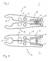
- Fig. 2 is an abstracted plan view of a gripping device 1 of two gripping arms 2 and 3 according to the invention in an open position shown.
- the device 1 has the second, corresponding gripper arm 3.
- the two gripping arms 2 and 3 are arranged and formed mirror-symmetrically to each other.
- the open position of the illustrated gripping device 1 is characterized in that between the gripping portions 5 in the front portion 12 of the gripping arms 2 and 3, a container, preferably from a front side of the gripping device 1, can be guided.
- the device 1 has a control cam 11, which is arranged between the suspension means 16 of the two gripping arms 2 and 3.
- the control cam 11 is 360 degrees, preferably about 200 degrees, about a control axis 7, which preferably corresponds to its axis of symmetry, rotatable. In this case, the control cam 7 against a stop (not shown).
- control cam 7 engages in an end position, which can be changed by means of a defined ⁇ ffnerkraft or closing force and does not cause a change on its own.
- control cam 11 is set such that a distance between the suspension means 16 of the two gripping arms 2 and 3 is as small as possible and preferably corresponds to the thickness of the control cam at its narrowest point.
- Fig. 3 is an abstracted plan view of the gripping device 1 of two gripping arms 2 and 3 according to the invention in a closed position shown.
- the gripping device 1 corresponds to the gripping device Fig. 2 and differs only in that the control cam 11 is rotated about the control axis 7 by about 90 degrees. A resulting in the closed position distance between the suspension means 16 of the two gripping arms 2 and 3 is thereby increased and a distance between the front portions 12 is reduced.
- the distance between the suspension means 16 preferably corresponds to the thickness of the control cam at its widest point.
- the spring means 16 is not pressed in this position, even if a container is held, to reduce the material stress of the spring bar 17. As described above, the spring means 16 helps to compensate for exceptionally occurring material tolerances of containers to be gripped or deviations of the gripping width caused by a container which is inclined.
Landscapes
- Engineering & Computer Science (AREA)
- Mechanical Engineering (AREA)
- Manufacturing & Machinery (AREA)
- Filling Of Jars Or Cans And Processes For Cleaning And Sealing Jars (AREA)
- Manipulator (AREA)
- Specific Conveyance Elements (AREA)
- Gripping Jigs, Holding Jigs, And Positioning Jigs (AREA)
- Details Of Rigid Or Semi-Rigid Containers (AREA)
- Clamps And Clips (AREA)
Priority Applications (8)
| Application Number | Priority Date | Filing Date | Title |
|---|---|---|---|
| ES13155971T ES2531199T3 (es) | 2013-02-20 | 2013-02-20 | Brazo de agarre para recipientes y procedimiento para la producción de un brazo de agarre de este tipo |
| EP20130155971 EP2769941B1 (fr) | 2013-02-20 | 2013-02-20 | Bras de préhension pour récipients ainsi que le procédé pour fabriquer tel bras de préhension |
| EA201490239A EA025385B1 (ru) | 2013-02-20 | 2014-02-07 | Захватная рукоятка для емкостей |
| MX2014001814A MX350018B (es) | 2013-02-20 | 2014-02-14 | Brazo sujetador para recipientes. |
| BR102014003905-8A BR102014003905B1 (pt) | 2013-02-20 | 2014-02-19 | braço de pinça e método para fabricar um braço de pinça |
| US14/184,231 US9102479B2 (en) | 2013-02-20 | 2014-02-19 | Gripper arm with integral spring bar for grasping, holding and guiding bottle-like containers |
| JP2014029229A JP6290646B2 (ja) | 2013-02-20 | 2014-02-19 | グリッパアーム、およびグリッパアームを製造するための方法 |
| CN201410058387.6A CN104002310B (zh) | 2013-02-20 | 2014-02-20 | 用于容器的夹持臂 |
Applications Claiming Priority (1)
| Application Number | Priority Date | Filing Date | Title |
|---|---|---|---|
| EP20130155971 EP2769941B1 (fr) | 2013-02-20 | 2013-02-20 | Bras de préhension pour récipients ainsi que le procédé pour fabriquer tel bras de préhension |
Publications (2)
| Publication Number | Publication Date |
|---|---|
| EP2769941A1 true EP2769941A1 (fr) | 2014-08-27 |
| EP2769941B1 EP2769941B1 (fr) | 2015-01-14 |
Family
ID=47748489
Family Applications (1)
| Application Number | Title | Priority Date | Filing Date |
|---|---|---|---|
| EP20130155971 Active EP2769941B1 (fr) | 2013-02-20 | 2013-02-20 | Bras de préhension pour récipients ainsi que le procédé pour fabriquer tel bras de préhension |
Country Status (8)
| Country | Link |
|---|---|
| US (1) | US9102479B2 (fr) |
| EP (1) | EP2769941B1 (fr) |
| JP (1) | JP6290646B2 (fr) |
| CN (1) | CN104002310B (fr) |
| BR (1) | BR102014003905B1 (fr) |
| EA (1) | EA025385B1 (fr) |
| ES (1) | ES2531199T3 (fr) |
| MX (1) | MX350018B (fr) |
Cited By (2)
| Publication number | Priority date | Publication date | Assignee | Title |
|---|---|---|---|---|
| CN109015727A (zh) * | 2018-08-23 | 2018-12-18 | 江苏新美星包装机械股份有限公司 | 一种开合式机械手 |
| EP3816076A1 (fr) | 2019-10-30 | 2021-05-05 | Tyrolon-Schulnig GmbH | Dispositif d'appréhension ainsi que dispositif de transport permettant d'appréhender, de maintenir et de guider, en particulier des récipients de type bouteille |
Families Citing this family (14)
| Publication number | Priority date | Publication date | Assignee | Title |
|---|---|---|---|---|
| FR3045584B1 (fr) * | 2015-12-16 | 2018-01-12 | Sidel Participations | Pince de prehension d'un corps creux tel qu'une preforme de recipient ou un recipient |
| JP1613460S (fr) * | 2017-03-09 | 2018-09-10 | ||
| CN107879095A (zh) * | 2017-11-30 | 2018-04-06 | 嘉兴市杰希希管道工程有限公司 | 一种管件抓举收料装置 |
| DE102017129506A1 (de) * | 2017-12-11 | 2019-06-13 | Krones Ag | Aktive Klammervorrichtung |
| DE102018104112A1 (de) * | 2018-02-23 | 2019-08-29 | Khs Gmbh | Greifer für ein Behältertransportsystem |
| US10899558B2 (en) | 2018-11-08 | 2021-01-26 | Federal Mfg. Llc | Bottle neck gripper |
| DE102019113653A1 (de) | 2019-05-22 | 2020-11-26 | Krones Ag | Vorrichtung zum Halten eines Behälters und Verschließvorrichtung |
| DE102019209755B4 (de) * | 2019-07-03 | 2021-08-05 | Festo Se & Co. Kg | Verbindung zwischen Grundkörper und Greifeinheit einer Greifvorrichtung |
| DE102019131587A1 (de) | 2019-11-22 | 2021-05-27 | Krones Aktiengesellschaft | Klammervorrichtung zum Halten eines Behälters |
| CN111216153B (zh) * | 2019-12-04 | 2023-01-24 | 吉林工程技术师范学院 | 陶瓷瓶夹取装置 |
| DE102020113601A1 (de) * | 2020-05-20 | 2021-11-25 | Krones Aktiengesellschaft | Klammervorrichtung und Behälterbehandlungsvorrichtung |
| CN112655288B (zh) * | 2020-12-22 | 2022-03-08 | 浙江理工大学 | 一种水田株间锄草装置 |
| US11866273B2 (en) | 2021-01-07 | 2024-01-09 | Bartelt Packaging Llc | Magnetic pouch clamp assembly and related methods |
| DE102021117666A1 (de) * | 2021-07-08 | 2023-01-12 | Krones Aktiengesellschaft | Behälterklammer für unterschiedliche Behälterarten |
Citations (8)
| Publication number | Priority date | Publication date | Assignee | Title |
|---|---|---|---|---|
| DE19542337A1 (de) * | 1995-11-14 | 1997-05-15 | Hermann Kronseder | Transportstern für Gefäße |
| EP0939044A1 (fr) * | 1998-02-26 | 1999-09-01 | Hermann Kronseder | Pince de bouteille |
| DE29915927U1 (de) * | 1999-09-10 | 2000-02-17 | Krones Ag | Flaschengreifer |
| EP1851146A1 (fr) | 2005-02-23 | 2007-11-07 | Krones AG | Pince de serrage pour un systeme de transport de recipients |
| EP1868746B1 (fr) * | 2005-03-30 | 2009-05-06 | Krones AG | Bride de fixation pour fixer des recipients |
| EP2143674A2 (fr) * | 2008-07-12 | 2010-01-13 | Krones AG | Pince de préhension de conteneurs |
| EP2343255A1 (fr) * | 2010-01-07 | 2011-07-13 | Tyrolon-Schulnig GmbH | Dispositif de saisie pour une roue convoyeuse à étoile et roue convoyeuse à étoile |
| DE102010052348A1 (de) * | 2010-11-25 | 2012-05-31 | Khs Gmbh | PET-Flaschen-Greifvorrichtung |
Family Cites Families (10)
| Publication number | Priority date | Publication date | Assignee | Title |
|---|---|---|---|---|
| US4336927A (en) * | 1980-05-08 | 1982-06-29 | Goff Otis W | Light-weight jam-clamp and combination |
| ES2129902T3 (es) * | 1995-05-13 | 1999-06-16 | Hermann Kronseder | Rueda transportadora en estrella para recipientes. |
| DE59708686D1 (de) * | 1996-03-13 | 2002-12-19 | Hermann Kronseder | Transportstern für Gefässe |
| DE29713510U1 (de) * | 1997-07-30 | 1998-08-27 | Kronseder Maschf Krones | Rotationsfüller |
| FR2770292B1 (fr) * | 1997-10-24 | 1999-12-10 | Serac Group | Dispositif de pesage de recipients par prehension en porte-a-faux |
| CN2486269Y (zh) * | 2001-07-19 | 2002-04-17 | 姚德利 | 一种机械式快速压线钳 |
| US6557695B2 (en) * | 2001-08-01 | 2003-05-06 | Owens-Brockway Glass Container Inc. | Apparatus and method for inspecting non-round containers |
| DE202005014171U1 (de) * | 2005-09-02 | 2007-01-18 | Bessey Tool Gmbh & Co. Kg | Ratschenzwinge |
| JP2011515302A (ja) * | 2008-03-26 | 2011-05-19 | シデル パーティシペイションズ | 首によってコンテナを保持するための弾力的なクランプ |
| DE102008055616B4 (de) * | 2008-11-03 | 2015-02-05 | Khs Gmbh | Vorrichtung zum Greifen von PET-Flaschen in Flaschenabfüllanlagen oder dergleichen, sowie eine Transportvorrichtung und ein Transport- und Übergabeverfahren |
-
2013
- 2013-02-20 ES ES13155971T patent/ES2531199T3/es active Active
- 2013-02-20 EP EP20130155971 patent/EP2769941B1/fr active Active
-
2014
- 2014-02-07 EA EA201490239A patent/EA025385B1/ru not_active IP Right Cessation
- 2014-02-14 MX MX2014001814A patent/MX350018B/es active IP Right Grant
- 2014-02-19 BR BR102014003905-8A patent/BR102014003905B1/pt active IP Right Grant
- 2014-02-19 JP JP2014029229A patent/JP6290646B2/ja active Active
- 2014-02-19 US US14/184,231 patent/US9102479B2/en active Active
- 2014-02-20 CN CN201410058387.6A patent/CN104002310B/zh active Active
Patent Citations (9)
| Publication number | Priority date | Publication date | Assignee | Title |
|---|---|---|---|---|
| DE19542337A1 (de) * | 1995-11-14 | 1997-05-15 | Hermann Kronseder | Transportstern für Gefäße |
| EP0939044A1 (fr) * | 1998-02-26 | 1999-09-01 | Hermann Kronseder | Pince de bouteille |
| DE29915927U1 (de) * | 1999-09-10 | 2000-02-17 | Krones Ag | Flaschengreifer |
| EP1851146A1 (fr) | 2005-02-23 | 2007-11-07 | Krones AG | Pince de serrage pour un systeme de transport de recipients |
| EP2548824A1 (fr) * | 2005-02-23 | 2013-01-23 | Krones AG | Pince de fixation pour un système de transport de récipients |
| EP1868746B1 (fr) * | 2005-03-30 | 2009-05-06 | Krones AG | Bride de fixation pour fixer des recipients |
| EP2143674A2 (fr) * | 2008-07-12 | 2010-01-13 | Krones AG | Pince de préhension de conteneurs |
| EP2343255A1 (fr) * | 2010-01-07 | 2011-07-13 | Tyrolon-Schulnig GmbH | Dispositif de saisie pour une roue convoyeuse à étoile et roue convoyeuse à étoile |
| DE102010052348A1 (de) * | 2010-11-25 | 2012-05-31 | Khs Gmbh | PET-Flaschen-Greifvorrichtung |
Cited By (2)
| Publication number | Priority date | Publication date | Assignee | Title |
|---|---|---|---|---|
| CN109015727A (zh) * | 2018-08-23 | 2018-12-18 | 江苏新美星包装机械股份有限公司 | 一种开合式机械手 |
| EP3816076A1 (fr) | 2019-10-30 | 2021-05-05 | Tyrolon-Schulnig GmbH | Dispositif d'appréhension ainsi que dispositif de transport permettant d'appréhender, de maintenir et de guider, en particulier des récipients de type bouteille |
Also Published As
| Publication number | Publication date |
|---|---|
| BR102014003905A2 (pt) | 2016-11-01 |
| CN104002310A (zh) | 2014-08-27 |
| EA025385B1 (ru) | 2016-12-30 |
| EA201490239A1 (ru) | 2014-09-30 |
| US20140232126A1 (en) | 2014-08-21 |
| ES2531199T3 (es) | 2015-03-11 |
| JP6290646B2 (ja) | 2018-03-07 |
| CN104002310B (zh) | 2017-08-11 |
| MX350018B (es) | 2017-08-23 |
| BR102014003905B1 (pt) | 2021-02-23 |
| EP2769941B1 (fr) | 2015-01-14 |
| JP2014159074A (ja) | 2014-09-04 |
| US9102479B2 (en) | 2015-08-11 |
| MX2014001814A (es) | 2014-11-04 |
Similar Documents
| Publication | Publication Date | Title |
|---|---|---|
| EP2769941B1 (fr) | Bras de préhension pour récipients ainsi que le procédé pour fabriquer tel bras de préhension | |
| EP3397577B1 (fr) | Bras de préhension pour contenants et dispositif de préhension comprenant des bras de préhension de ce type | |
| EP1868746B1 (fr) | Bride de fixation pour fixer des recipients | |
| EP3224165B1 (fr) | Dispositif de transport de contenants | |
| DE102014111564B4 (de) | Greifarm für Behälter, Steuernocken, Lagereinheit und Greifeinrichtung | |
| DE102008055616B4 (de) | Vorrichtung zum Greifen von PET-Flaschen in Flaschenabfüllanlagen oder dergleichen, sowie eine Transportvorrichtung und ein Transport- und Übergabeverfahren | |
| DE102006056943A1 (de) | Verfahren zum Transport von Gegenständen | |
| EP2295352A2 (fr) | Dispositif de prise pour tenir et déplacer des articles | |
| EP3505469A2 (fr) | Dispositif de serrage actif | |
| EP1999048A1 (fr) | Élément de saisie | |
| EP3405416B1 (fr) | Procédé de guidage et de pivotement d'objets, système et lignes de transport pour récipients en pet | |
| WO2020108758A1 (fr) | Dispositif de préhension, de retenue et de guidage de récipients, et procédé permettant d'actionner un tel dispositif | |
| DE102014018778A1 (de) | Maschine zur Herstellung von mit einem flüssigen Füllgut gefüllten Behältern aus Vorformlingen aus einem thermoplastischen Material | |
| EP2774878B1 (fr) | Bras de préhension pour un dispositif de préhension ainsi que la machine pour transporter des récipients au moyen de ces bras de préhension | |
| DE102012107361A1 (de) | Abdichteinrichtung mit Kompensationsmöglichkeit für mehrere Bewegungsrichtungen | |
| EP2142458B1 (fr) | Dispositif de paraffinage pour un poste de travail d'une machine textile fabriquant des bobines croisées | |
| EP3907161A1 (fr) | Dispositif de collier de serrage passif et collier de serrage passif | |
| DE102014105974A1 (de) | Behälterbehandlungsmaschine sowie Verfahren zum Behandeln von Behältern | |
| EP2821151B1 (fr) | Dispositif de transport d'un récipient dans une installation de nettoyage de récipient | |
| EP2774877A1 (fr) | Dispositif de préhension destiné à saisir et à maintenir des bouteilles, des boîtes ou des récipients à liquide similaires, roue convoyeuse en étoile dotée d'un tel dispositif de préhension ainsi que le procédé de fabrication | |
| EP0531872B1 (fr) | Appareil pour transporter des bouteilles en plastiques dans une machine de lavage de bouteilles | |
| DE102017105024B4 (de) | Rinsersystem | |
| DE102018008265A1 (de) | Ventil, insbesondere Rückschlagventil | |
| EP2735429A1 (fr) | Dispositif de traitement de récipient doté d'un dispositif d'étirage | |
| DE102015114567B4 (de) | Einsetzbare Ansteuerungsvorrichtung und Transportvorrichtung für Behälter, sowie schwebend positionierte Ansteuerungsvorrichtung |
Legal Events
| Date | Code | Title | Description |
|---|---|---|---|
| PUAI | Public reference made under article 153(3) epc to a published international application that has entered the european phase |
Free format text: ORIGINAL CODE: 0009012 |
|
| 17P | Request for examination filed |
Effective date: 20140214 |
|
| AK | Designated contracting states |
Kind code of ref document: A1 Designated state(s): AL AT BE BG CH CY CZ DE DK EE ES FI FR GB GR HR HU IE IS IT LI LT LU LV MC MK MT NL NO PL PT RO RS SE SI SK SM TR |
|
| AX | Request for extension of the european patent |
Extension state: BA ME |
|
| 17Q | First examination report despatched |
Effective date: 20140731 |
|
| GRAP | Despatch of communication of intention to grant a patent |
Free format text: ORIGINAL CODE: EPIDOSNIGR1 |
|
| INTG | Intention to grant announced |
Effective date: 20140919 |
|
| GRAS | Grant fee paid |
Free format text: ORIGINAL CODE: EPIDOSNIGR3 |
|
| GRAP | Despatch of communication of intention to grant a patent |
Free format text: ORIGINAL CODE: EPIDOSNIGR1 |
|
| INTG | Intention to grant announced |
Effective date: 20141121 |
|
| GRAA | (expected) grant |
Free format text: ORIGINAL CODE: 0009210 |
|
| AK | Designated contracting states |
Kind code of ref document: B1 Designated state(s): AL AT BE BG CH CY CZ DE DK EE ES FI FR GB GR HR HU IE IS IT LI LT LU LV MC MK MT NL NO PL PT RO RS SE SI SK SM TR |
|
| REG | Reference to a national code |
Ref country code: GB Ref legal event code: FG4D Free format text: NOT ENGLISH |
|
| REG | Reference to a national code |
Ref country code: CH Ref legal event code: EP |
|
| REG | Reference to a national code |
Ref country code: IE Ref legal event code: FG4D Free format text: LANGUAGE OF EP DOCUMENT: GERMAN |
|
| REG | Reference to a national code |
Ref country code: AT Ref legal event code: REF Ref document number: 706914 Country of ref document: AT Kind code of ref document: T Effective date: 20150215 |
|
| REG | Reference to a national code |
Ref country code: DE Ref legal event code: R096 Ref document number: 502013000300 Country of ref document: DE Effective date: 20150226 |
|
| REG | Reference to a national code |
Ref country code: ES Ref legal event code: FG2A Ref document number: 2531199 Country of ref document: ES Kind code of ref document: T3 Effective date: 20150311 |
|
| REG | Reference to a national code |
Ref country code: NL Ref legal event code: VDEP Effective date: 20150114 |
|
| REG | Reference to a national code |
Ref country code: LT Ref legal event code: MG4D |
|
| PG25 | Lapsed in a contracting state [announced via postgrant information from national office to epo] |
Ref country code: BE Free format text: LAPSE BECAUSE OF NON-PAYMENT OF DUE FEES Effective date: 20150228 |
|
| PG25 | Lapsed in a contracting state [announced via postgrant information from national office to epo] |
Ref country code: LT Free format text: LAPSE BECAUSE OF FAILURE TO SUBMIT A TRANSLATION OF THE DESCRIPTION OR TO PAY THE FEE WITHIN THE PRESCRIBED TIME-LIMIT Effective date: 20150114 Ref country code: SE Free format text: LAPSE BECAUSE OF FAILURE TO SUBMIT A TRANSLATION OF THE DESCRIPTION OR TO PAY THE FEE WITHIN THE PRESCRIBED TIME-LIMIT Effective date: 20150114 Ref country code: HR Free format text: LAPSE BECAUSE OF FAILURE TO SUBMIT A TRANSLATION OF THE DESCRIPTION OR TO PAY THE FEE WITHIN THE PRESCRIBED TIME-LIMIT Effective date: 20150114 Ref country code: NO Free format text: LAPSE BECAUSE OF FAILURE TO SUBMIT A TRANSLATION OF THE DESCRIPTION OR TO PAY THE FEE WITHIN THE PRESCRIBED TIME-LIMIT Effective date: 20150414 Ref country code: FI Free format text: LAPSE BECAUSE OF FAILURE TO SUBMIT A TRANSLATION OF THE DESCRIPTION OR TO PAY THE FEE WITHIN THE PRESCRIBED TIME-LIMIT Effective date: 20150114 Ref country code: BG Free format text: LAPSE BECAUSE OF FAILURE TO SUBMIT A TRANSLATION OF THE DESCRIPTION OR TO PAY THE FEE WITHIN THE PRESCRIBED TIME-LIMIT Effective date: 20150414 |
|
| PG25 | Lapsed in a contracting state [announced via postgrant information from national office to epo] |
Ref country code: IS Free format text: LAPSE BECAUSE OF FAILURE TO SUBMIT A TRANSLATION OF THE DESCRIPTION OR TO PAY THE FEE WITHIN THE PRESCRIBED TIME-LIMIT Effective date: 20150514 Ref country code: GR Free format text: LAPSE BECAUSE OF FAILURE TO SUBMIT A TRANSLATION OF THE DESCRIPTION OR TO PAY THE FEE WITHIN THE PRESCRIBED TIME-LIMIT Effective date: 20150415 Ref country code: NL Free format text: LAPSE BECAUSE OF FAILURE TO SUBMIT A TRANSLATION OF THE DESCRIPTION OR TO PAY THE FEE WITHIN THE PRESCRIBED TIME-LIMIT Effective date: 20150114 Ref country code: RS Free format text: LAPSE BECAUSE OF FAILURE TO SUBMIT A TRANSLATION OF THE DESCRIPTION OR TO PAY THE FEE WITHIN THE PRESCRIBED TIME-LIMIT Effective date: 20150114 Ref country code: PL Free format text: LAPSE BECAUSE OF FAILURE TO SUBMIT A TRANSLATION OF THE DESCRIPTION OR TO PAY THE FEE WITHIN THE PRESCRIBED TIME-LIMIT Effective date: 20150114 Ref country code: LV Free format text: LAPSE BECAUSE OF FAILURE TO SUBMIT A TRANSLATION OF THE DESCRIPTION OR TO PAY THE FEE WITHIN THE PRESCRIBED TIME-LIMIT Effective date: 20150114 |
|
| REG | Reference to a national code |
Ref country code: DE Ref legal event code: R097 Ref document number: 502013000300 Country of ref document: DE |
|
| PG25 | Lapsed in a contracting state [announced via postgrant information from national office to epo] |
Ref country code: MC Free format text: LAPSE BECAUSE OF FAILURE TO SUBMIT A TRANSLATION OF THE DESCRIPTION OR TO PAY THE FEE WITHIN THE PRESCRIBED TIME-LIMIT Effective date: 20150114 Ref country code: RO Free format text: LAPSE BECAUSE OF FAILURE TO SUBMIT A TRANSLATION OF THE DESCRIPTION OR TO PAY THE FEE WITHIN THE PRESCRIBED TIME-LIMIT Effective date: 20150114 Ref country code: EE Free format text: LAPSE BECAUSE OF FAILURE TO SUBMIT A TRANSLATION OF THE DESCRIPTION OR TO PAY THE FEE WITHIN THE PRESCRIBED TIME-LIMIT Effective date: 20150114 Ref country code: DK Free format text: LAPSE BECAUSE OF FAILURE TO SUBMIT A TRANSLATION OF THE DESCRIPTION OR TO PAY THE FEE WITHIN THE PRESCRIBED TIME-LIMIT Effective date: 20150114 Ref country code: SK Free format text: LAPSE BECAUSE OF FAILURE TO SUBMIT A TRANSLATION OF THE DESCRIPTION OR TO PAY THE FEE WITHIN THE PRESCRIBED TIME-LIMIT Effective date: 20150114 Ref country code: CZ Free format text: LAPSE BECAUSE OF FAILURE TO SUBMIT A TRANSLATION OF THE DESCRIPTION OR TO PAY THE FEE WITHIN THE PRESCRIBED TIME-LIMIT Effective date: 20150114 |
|
| REG | Reference to a national code |
Ref country code: IE Ref legal event code: MM4A |
|
| PLBE | No opposition filed within time limit |
Free format text: ORIGINAL CODE: 0009261 |
|
| STAA | Information on the status of an ep patent application or granted ep patent |
Free format text: STATUS: NO OPPOSITION FILED WITHIN TIME LIMIT |
|
| 26N | No opposition filed |
Effective date: 20151015 |
|
| PG25 | Lapsed in a contracting state [announced via postgrant information from national office to epo] |
Ref country code: IE Free format text: LAPSE BECAUSE OF NON-PAYMENT OF DUE FEES Effective date: 20150220 |
|
| PG25 | Lapsed in a contracting state [announced via postgrant information from national office to epo] |
Ref country code: SI Free format text: LAPSE BECAUSE OF FAILURE TO SUBMIT A TRANSLATION OF THE DESCRIPTION OR TO PAY THE FEE WITHIN THE PRESCRIBED TIME-LIMIT Effective date: 20150114 |
|
| REG | Reference to a national code |
Ref country code: FR Ref legal event code: PLFP Year of fee payment: 4 |
|
| REG | Reference to a national code |
Ref country code: CH Ref legal event code: PL |
|
| PG25 | Lapsed in a contracting state [announced via postgrant information from national office to epo] |
Ref country code: CH Free format text: LAPSE BECAUSE OF NON-PAYMENT OF DUE FEES Effective date: 20160229 Ref country code: LI Free format text: LAPSE BECAUSE OF NON-PAYMENT OF DUE FEES Effective date: 20160229 |
|
| PG25 | Lapsed in a contracting state [announced via postgrant information from national office to epo] |
Ref country code: MT Free format text: LAPSE BECAUSE OF FAILURE TO SUBMIT A TRANSLATION OF THE DESCRIPTION OR TO PAY THE FEE WITHIN THE PRESCRIBED TIME-LIMIT Effective date: 20150114 |
|
| REG | Reference to a national code |
Ref country code: FR Ref legal event code: PLFP Year of fee payment: 5 |
|
| PG25 | Lapsed in a contracting state [announced via postgrant information from national office to epo] |
Ref country code: HU Free format text: LAPSE BECAUSE OF FAILURE TO SUBMIT A TRANSLATION OF THE DESCRIPTION OR TO PAY THE FEE WITHIN THE PRESCRIBED TIME-LIMIT; INVALID AB INITIO Effective date: 20130220 |
|
| PG25 | Lapsed in a contracting state [announced via postgrant information from national office to epo] |
Ref country code: CY Free format text: LAPSE BECAUSE OF FAILURE TO SUBMIT A TRANSLATION OF THE DESCRIPTION OR TO PAY THE FEE WITHIN THE PRESCRIBED TIME-LIMIT Effective date: 20150114 |
|
| PG25 | Lapsed in a contracting state [announced via postgrant information from national office to epo] |
Ref country code: TR Free format text: LAPSE BECAUSE OF FAILURE TO SUBMIT A TRANSLATION OF THE DESCRIPTION OR TO PAY THE FEE WITHIN THE PRESCRIBED TIME-LIMIT Effective date: 20150114 |
|
| PG25 | Lapsed in a contracting state [announced via postgrant information from national office to epo] |
Ref country code: LU Free format text: LAPSE BECAUSE OF NON-PAYMENT OF DUE FEES Effective date: 20150220 |
|
| REG | Reference to a national code |
Ref country code: FR Ref legal event code: PLFP Year of fee payment: 6 |
|
| PG25 | Lapsed in a contracting state [announced via postgrant information from national office to epo] |
Ref country code: SM Free format text: LAPSE BECAUSE OF FAILURE TO SUBMIT A TRANSLATION OF THE DESCRIPTION OR TO PAY THE FEE WITHIN THE PRESCRIBED TIME-LIMIT Effective date: 20150114 |
|
| PG25 | Lapsed in a contracting state [announced via postgrant information from national office to epo] |
Ref country code: MK Free format text: LAPSE BECAUSE OF FAILURE TO SUBMIT A TRANSLATION OF THE DESCRIPTION OR TO PAY THE FEE WITHIN THE PRESCRIBED TIME-LIMIT Effective date: 20150114 Ref country code: PT Free format text: LAPSE BECAUSE OF FAILURE TO SUBMIT A TRANSLATION OF THE DESCRIPTION OR TO PAY THE FEE WITHIN THE PRESCRIBED TIME-LIMIT Effective date: 20150114 |
|
| PG25 | Lapsed in a contracting state [announced via postgrant information from national office to epo] |
Ref country code: AL Free format text: LAPSE BECAUSE OF FAILURE TO SUBMIT A TRANSLATION OF THE DESCRIPTION OR TO PAY THE FEE WITHIN THE PRESCRIBED TIME-LIMIT Effective date: 20150114 |
|
| REG | Reference to a national code |
Ref country code: AT Ref legal event code: MM01 Ref document number: 706914 Country of ref document: AT Kind code of ref document: T Effective date: 20180220 |
|
| PG25 | Lapsed in a contracting state [announced via postgrant information from national office to epo] |
Ref country code: AT Free format text: LAPSE BECAUSE OF NON-PAYMENT OF DUE FEES Effective date: 20180220 |
|
| PGFP | Annual fee paid to national office [announced via postgrant information from national office to epo] |
Ref country code: FR Payment date: 20230223 Year of fee payment: 11 Ref country code: ES Payment date: 20230321 Year of fee payment: 11 |
|
| PGFP | Annual fee paid to national office [announced via postgrant information from national office to epo] |
Ref country code: IT Payment date: 20230220 Year of fee payment: 11 |
|
| PGFP | Annual fee paid to national office [announced via postgrant information from national office to epo] |
Ref country code: ES Payment date: 20240307 Year of fee payment: 12 |
|
| PGFP | Annual fee paid to national office [announced via postgrant information from national office to epo] |
Ref country code: DE Payment date: 20240228 Year of fee payment: 12 Ref country code: GB Payment date: 20240220 Year of fee payment: 12 |