EP3397577B1 - Bras de préhension pour contenants et dispositif de préhension comprenant des bras de préhension de ce type - Google Patents
Bras de préhension pour contenants et dispositif de préhension comprenant des bras de préhension de ce type Download PDFInfo
- Publication number
- EP3397577B1 EP3397577B1 EP17700320.9A EP17700320A EP3397577B1 EP 3397577 B1 EP3397577 B1 EP 3397577B1 EP 17700320 A EP17700320 A EP 17700320A EP 3397577 B1 EP3397577 B1 EP 3397577B1
- Authority
- EP
- European Patent Office
- Prior art keywords
- gripper arm
- gripping
- gripper
- arm
- spring tongue
- Prior art date
- Legal status (The legal status is an assumption and is not a legal conclusion. Google has not performed a legal analysis and makes no representation as to the accuracy of the status listed.)
- Active
Links
Images


Classifications
-
- B—PERFORMING OPERATIONS; TRANSPORTING
- B65—CONVEYING; PACKING; STORING; HANDLING THIN OR FILAMENTARY MATERIAL
- B65G—TRANSPORT OR STORAGE DEVICES, e.g. CONVEYORS FOR LOADING OR TIPPING, SHOP CONVEYOR SYSTEMS OR PNEUMATIC TUBE CONVEYORS
- B65G47/00—Article or material-handling devices associated with conveyors; Methods employing such devices
- B65G47/74—Feeding, transfer, or discharging devices of particular kinds or types
- B65G47/84—Star-shaped wheels or devices having endless travelling belts or chains, the wheels or devices being equipped with article-engaging elements
- B65G47/846—Star-shaped wheels or wheels equipped with article-engaging elements
- B65G47/847—Star-shaped wheels or wheels equipped with article-engaging elements the article-engaging elements being grippers
-
- B—PERFORMING OPERATIONS; TRANSPORTING
- B65—CONVEYING; PACKING; STORING; HANDLING THIN OR FILAMENTARY MATERIAL
- B65G—TRANSPORT OR STORAGE DEVICES, e.g. CONVEYORS FOR LOADING OR TIPPING, SHOP CONVEYOR SYSTEMS OR PNEUMATIC TUBE CONVEYORS
- B65G47/00—Article or material-handling devices associated with conveyors; Methods employing such devices
- B65G47/74—Feeding, transfer, or discharging devices of particular kinds or types
- B65G47/90—Devices for picking-up and depositing articles or materials
-
- B—PERFORMING OPERATIONS; TRANSPORTING
- B67—OPENING, CLOSING OR CLEANING BOTTLES, JARS OR SIMILAR CONTAINERS; LIQUID HANDLING
- B67C—CLEANING, FILLING WITH LIQUIDS OR SEMILIQUIDS, OR EMPTYING, OF BOTTLES, JARS, CANS, CASKS, BARRELS, OR SIMILAR CONTAINERS, NOT OTHERWISE PROVIDED FOR; FUNNELS
- B67C3/00—Bottling liquids or semiliquids; Filling jars or cans with liquids or semiliquids using bottling or like apparatus; Filling casks or barrels with liquids or semiliquids
- B67C3/02—Bottling liquids or semiliquids; Filling jars or cans with liquids or semiliquids using bottling or like apparatus
- B67C3/22—Details
- B67C3/24—Devices for supporting or handling bottles
- B67C3/242—Devices for supporting or handling bottles engaging with bottle necks
-
- B—PERFORMING OPERATIONS; TRANSPORTING
- B65—CONVEYING; PACKING; STORING; HANDLING THIN OR FILAMENTARY MATERIAL
- B65G—TRANSPORT OR STORAGE DEVICES, e.g. CONVEYORS FOR LOADING OR TIPPING, SHOP CONVEYOR SYSTEMS OR PNEUMATIC TUBE CONVEYORS
- B65G2201/00—Indexing codes relating to handling devices, e.g. conveyors, characterised by the type of product or load being conveyed or handled
- B65G2201/02—Articles
- B65G2201/0235—Containers
- B65G2201/0244—Bottles
-
- B—PERFORMING OPERATIONS; TRANSPORTING
- B67—OPENING, CLOSING OR CLEANING BOTTLES, JARS OR SIMILAR CONTAINERS; LIQUID HANDLING
- B67C—CLEANING, FILLING WITH LIQUIDS OR SEMILIQUIDS, OR EMPTYING, OF BOTTLES, JARS, CANS, CASKS, BARRELS, OR SIMILAR CONTAINERS, NOT OTHERWISE PROVIDED FOR; FUNNELS
- B67C3/00—Bottling liquids or semiliquids; Filling jars or cans with liquids or semiliquids using bottling or like apparatus; Filling casks or barrels with liquids or semiliquids
- B67C3/02—Bottling liquids or semiliquids; Filling jars or cans with liquids or semiliquids using bottling or like apparatus
- B67C3/22—Details
- B67C2003/228—Aseptic features
Definitions
- the present invention relates to a gripping arm for a device for gripping, holding and guiding, in particular bottle-like containers, and a gripping device with such gripping arms.
- the gripping arm forms part of a device which has a control means for moving a gripping section of the gripping arm from an open position to a gripping position or vice versa.
- the gripping arm itself has a bore for mounting a bearing pin for pivotably fastening the gripping arm in the device, and an energy store for moving the gripping section of the gripping arm from the gripping position to the open position or vice versa.
- bottle-like containers for example beverage bottles made of glass or plastic, but also bottles for pharmaceuticals or perfume.
- the term also includes other glass or plastic containers which, similar to a bottle, in particular have a neck or a structure tapering towards the opening.
- Such a gripper arm is basically known from the prior art and is used in the assembly line processing of containers.
- the containers are used by one Entrance station gripped by means of a gripping device with at least one pair of gripping arms and transported to the next station in the process.
- clamp gripper Such a device is for example in the patent application WO2006 / 089610 disclosed.
- the gripping device described therein called “clamp gripper” there, is intended for a vessel transport system, the gripping device having two gripping arms and being able to switch between a gripping position and an open position.
- an opening means is required, for example in the form of a spiral spring or a repelling magnet pair, which exerts a force on the two gripping arms and the gripping device thereby opens.
- the gripper arms normally have a predefined starting position into which they automatically return when no force is exerted on them by a control unit.
- control unit is designed as a mechanically acting control cam, the force and thus predominantly also the deflection of the gripping arms is compensated or cushioned by a spring means in the form of a leaf spring attached to each gripping arm.
- the spring means helps the gripping arms to compensate for material tolerances of containers to be gripped or deviations in the gripping distance caused by a container that is at an angle and thus to enable safe gripping and to avoid damage to the container.
- a similar and also known gripping device is in the German utility model DE 20 2005 002 924 U described.
- a spring is used as the opening means to open a pair of gripper arms.
- DE 299 15 927 U1 relates to a bottle gripper, in particular for a bottle transport device, with two gripping arms, each of which has a gripping end and possibly an actuating end, and which are held such that they can be moved in a pincer-like manner and with at least one rotationally adjustable actuating cam which acts on a contact surface of at least one gripping arm .
- the actuating cam acts indirectly on the contact surface via a sliding block, which has at least one sliding surface that contacts the contact surface.
- DE 299 15 927 U1 discloses the preamble of claim 1.
- US 8,672,376 B1 is directed to a gripper which is designed as a single component.
- the gripper comprises a tire section that faces each other Arms connects.
- Each arm may have a pin end, a jaw end, and a pin between the pin and jaw ends and be attached to the bracket portion at the pivot to pivot to change the size of a jaw opening defined by the jaw ends.
- the tire section is cyclically loaded and configured in use to act as a loading center for the gripper and to provide a failure point for continuously initiating a failure crack into the tire section at the time the gripper fails.
- Each of the mutually facing arms can be attached to a base so that the broken parts of the gripper are held on the base in the event of failure.
- the number of individual parts of the gripper arm is disadvantageous both for manufacture and assembly, and for maintenance and cleaning.
- logistical orders and deliveries must be made in order to receive all components and to be able to complete or maintain the gripper arm.
- additional assembly steps are required to assemble the gripper arm.
- the invention has for its object to provide a gripping arm that can be easily kept free of dirt and germs and has as few individual parts as possible.
- the object is achieved in a gripper arm mentioned at the outset in that the energy store has an integrally formed and elastically deflectable spring tongue on the gripper arm, which is or comes into active engagement with a spring tongue of an oppositely configured gripper arm of the device.
- integral means in particular belonging or connected.
- spring tongue means in particular but not exclusively an elastic or spring-loaded end piece, which due to its material and / or structural nature can be bent along at least part of its length and, in the case of no external force, returns or falls back to a starting / basic position.
- one end of the spring tongue is designed free or unbound and the opposite end is fastened or designed to an object, in this case the gripping arm.
- the spring tongue preferably has only one degree of freedom of bending, ie the spring tongue can essentially only be bent along one plane.
- the spring tongue is preferably designed such that, regardless of the location of the force acting on the spring tongue, essentially the entire width is deflected uniformly and thus there is no, at least no significant, rotation along the axis or the length of the spring tongue.
- the spring tongue which acts as an energy store, acts more stably in the event of an active intervention and acts in a tensioned or deflected state on or away from the gripping arm.
- the spring tongue has an end piece and a spring tongue web tapering towards the end piece.
- the spring tongue is sufficiently flexible and at the same time stably arranged or formed on the gripping arm in order to avoid premature cracks or breaks in the material.
- the spring tongue web mainly takes over the function of the energy store, while the end piece is designed to be stable and / or stiff enough to exert or transmit the force in a directed manner and without fluctuation.
- the spring tongue can serve as a closing means for the pair of gripper arms
- the spring tongues of the two gripper arms must be connected to one another.
- the spring tongue in particular its end piece, advantageously has a slot (or notch / notch) which is designed to come into active engagement with a spring tongue, in particular its slot, of a gripping arm of the gripping device of opposite design.
- the active intervention can be configured in particular as a cross-overlay.
- the spring tongue has essentially the same width as the gripping arm in the axial direction of the bore. As a result, the spring tongues cannot easily slide off one another and lose their operative engagement.
- the spring tongue in particular its end piece, is preferably spaced apart from a side face of the gripping arm facing the gripping arm of opposite design.
- This advantageous embodiment allows the spring tongue to serve as an opening means, since it can be deflected towards the gripping arm, in particular towards its side surface.
- the energy accumulator is formed between the bore and the gripping section and / or between the bore and an end section of the gripping arm.
- the gripping arm is advantageously made in one piece from, in particular, fiber-reinforced plastic and can therefore be used immediately in a gripping device.
- the fiber reinforcement enables a fiber-plastic composite of high specific rigidity and strength.
- Conventional gripper arms are made of stainless steel and are therefore relatively expensive.
- the metallic gripping arms occasionally bend, which is difficult to recognize on the one hand during operation of the device and on the other hand, which damage the containers to be gripped and transported and / or the opposite gripping arms hand over or take over the container and / or other fittings.
- the gripper arms are made of plastic, they can be manufactured very cheaply as disposable items by injection molding.
- plastic has better properties than stainless steel for this application, so that an overloading of the gripper arm does not cause it to bend, but rather to break immediately leads, which does not result in consequential damage to the bottle and enables immediate identification of the overstressed gripper arm. Then the gripper arm can be replaced very quickly and inexpensively due to its one-piece design.
- plastic also shows hardly any signs of wear when cleaning with water.
- a gripping arm molded from plastic creates an easily replaceable product that can be easily removed after its wear and tear and can be replaced without great costs or delivery times and without major downtime of the system, of which the gripping device is a component.
- the gripping section has a tapering and / or stepped profile tapering from the underside to the top of the gripping arm.
- the gripping arm has an integrally formed and elastically deflectable spring bar for compensating the force and / or deflection by the control means, the spring bar forming a closed circumferential recess with the gripping arm.
- the invention also relates to a gripping device with at least one pair of a gripping arm according to one of the aforementioned claims and a gripping arm of opposite design and with a control means for moving a gripping section of the gripping arm from an open position to a gripping position or vice versa.
- control means / unit can be designed as a control cam between a pair of gripper arms. Depending on its positioning, it acts either as an opening means (positioning between the hole and the gripping section) or as a closing means (positioning between the hole and the end section) of the gripping device.
- the gripper arm can be controlled directly via the bearing pin if the gripper arm is arranged on the bearing pin in a manner that prevents it from rotating. This is At the upper or lower end of the rotatably mounted bearing pin, a lever is formed, by the actuation or rotation of which the gripping arm can be pivoted at the same time.
- the oppositely designed gripping arm is controlled synchronously with its own lever or with a toothing element of the bearing pin, which is in operative engagement with a toothing element of the other bearing pin.
- the energy store functions in reverse as a closing means or opening means in order to automatically bring the gripping device into a starting position.
- the starting position can be either the gripping position or the open position depending on the function of the energy accumulator.
- the spring tongue can be rectilinear or curved and can be directed either in the direction of the end section or the gripping section of the gripping arm. Because e.g. In the gripping position, the spring tongues, in particular their end piece, essentially rest on the gripping arm, the elastic spring force can be increased in that the spring tongue is directed more away from the gripping arm in the non-deflected or non-bent state or the end piece continues away from the side surface of the gripping arm is spaced.
- FIG. 1 In the perspective view of Fig. 1 an inventive gripper arm 2 is shown.
- the gripping arm 2 is preferably elongated and is divided into a front section 12 and an end section 14.
- the gripping arm 2 is provided for a device for gripping, holding and guiding, in particular bottle-like containers, which has a rotatably mounted control cam (not shown here) for moving a gripping section 5 of the gripping arm 2 from an open position into a gripping position.
- a rotatably mounted control cam (not shown here) for moving a gripping section 5 of the gripping arm 2 from an open position into a gripping position.
- a bearing pin not shown here
- a spring tongue 6 is designed as an opening means for moving the gripping section 5 of the gripping arm 2 from the gripping position into the open position.
- a recess 8 is formed which is open towards the end of the spring tongue 6 towards the side of the gripping arm 2.
- This opening has a width that essentially defines the maximum deflection of the spring tongue 2 relative to the gripping arm 2.
- the interaction of the gripping section 5 with a gripping section of a second gripping arm, which is not shown here, is of opposite design and enables the gripping device to grasp and hold a container.
- a spring bar 16 is formed to cushion and compensate for the force and / or deflection exerted on the gripping arm 2 by the control cam.
- the spring bar 16 is integrally formed in an end portion 14 of the gripper arm body.
- the spring bar 16 forms with the end section 14 a closed recess 9, which provides the spring bar 16 with space for the required spring travel or an elastic deflection.
- the gripper arm 2 is made in one piece from plastic, preferably from fiber-reinforced polyether ether ketone.
- the gripping section 5 has a step-shaped profile that tapers from a lower side to an upper side of the gripping arm 2.
- the bore 10 corresponds to a continuous bore from the top to the bottom of the gripper arm 2, has a circular cross section and defines a pivot axis 4 which corresponds to an axis of symmetry of the bore 10.
- the pivot axis 4 extends perpendicular to the top and bottom.
- the gripping arm 2 can be produced in one piece from plastic by an injection molding process.
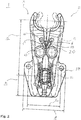
- FIG. 2 a technical drawing of a gripping device with the gripping arms according to the invention Fig. 1 shown.
- control cam 11 is shown as a control means, in particular a locking means, which is rotatably mounted in a carrier element 18 and is arranged between the end sections, in particular the spring bars, of the pair of gripper arms.
- the gripping arms 2, 3 are rotatably mounted by means of fastening screws and fastened to the carrier element 18. Both the gripping position and the opening position of the gripping device are shown in the drawing.
- the spring tongues 6 of the gripping arms 2, 3 act on one another and thereby bend elastically or exert a force on one another due to the deflection.
- Fig. 3 is a perspective view of the gripping device Fig. 2 , both in an exploded view and in an assembled state.
- the recesses in which the control cam 11 and the fastening screws 20 can be inserted can additionally be seen in the carrier element 18.
- the fastening screws 20 have a thread on the lower part for fastening in the carrier element 18, a cylindrical shape in the central region as a bearing for the bore of the gripping arm 2, 3 and a screw head on the upper part.
- Fig. 4 shows a representation of the spring tongues 6, 6 'as an advantageous embodiment from a gripping arm 2 according to the invention Fig. 1 or. Fig. 2 and a gripping arm 3 of opposite design Fig. 2 which are suitable to come into active engagement in the form of a cross overlay. Due to the active engagement, the spring tongues 6, 6 'are always connected to one another and can act as closing means. A notch / notch 19, 19 'is formed in each of the end pieces 13, 13' of the spring tongues 6, 6 '.
- the width of the notch 19 in the direction of the length of the spring tongue web 15 corresponds to the thickness / depth of the end piece 13 'or of the notch 19' perpendicular to the direction of the length of the spring tongue web 15 '(see dashed lines running in parallel). The same applies in reverse for the width of the notch 19 '. Since the spring tongues 6, 6 'are identical and mirror-inverted to each other and the notches 19, 19' are formed in the same position in the spring tongue 6, 6 ', the thickness and width of the notches 19, 19' are the same in this case or the base of the notches 19, 19 'is square. Dimensions in Fig. 1 Dimensions in Fig.
Claims (10)
- Bras de préhension (2) pour un dispositif de préhension, de maintien et de guidage de récipients en particulier du type bouteille, qui présente un moyen de commande (11) pour le déplacement d'une portion de préhension (5) du bras de préhension depuis une position ouverte jusqu'à une position de préhension, ou inversement, comprenant un alésage (10) pour le montage d'un tourillon (20) destiné à la fixation pivotante du bras de préhension (2) dans le dispositif, et comprenant un accumulateur d'énergie pour le déplacement de la portion de préhension (5) du bras de préhension depuis la position de préhension jusqu'à la position ouverte, ou inversement,
caractérisé en ce que
l'accumulateur d'énergie comporte une languette élastique (6) susceptible d'être déviée élastiquement et réalisée intégralement sur le bras de préhension, laquelle est ou vient en prise active avec une languette élastique (6') d'un bras de préhension (3) du dispositif réalisé de façon complémentaire symétrique. - Bras de préhension (2) selon la revendication 1,
caractérisé en ce que
la languette élastique (6) possède un embout (13) et une âme de languette (15) qui va en se rétrécissant vers l'embout (13). - Bras de préhension (2) selon la revendication 1 ou 2,
caractérisé en ce que
la languette élastique (6), en particulier son embout (13), est réalisé(e) de manière à venir en prise active avec la languette élastique (6') du bras de préhension (3) réalisé de façon complémentaire symétrique, en particulier avec son embout, sous la forme d'un chevauchement croisé. - Bras de préhension (2) selon l'une des revendications 1 à 3,
caractérisé en ce que
la languette élastique (6) a sensiblement la même largeur que le bras de préhension (2) dans la direction axiale de l'alésage (10). - Bras de préhension (2) selon l'une des revendications 1 à 4,
caractérisé en ce que
la languette élastique (6), en particulier son embout (13), est espacé(e) d'une surface latérale (17) du bras de préhension (2) tournée vers le bras de préhension (3) réalisé de façon complémentaire symétrique, à l'état détendu ou non dévié. - Bras de préhension (2) selon l'une des revendications 1 à 5,
caractérisé en ce que
l'accumulateur d'énergie est formé entre l'alésage (10) et la portion de préhension (5) et/ou entre l'alésage (10) et une portion d'extrémité (14) du bras de préhension (2). - Bras de préhension (2) selon l'une des revendications 1 à 6,
caractérisé en ce que
le bras de préhension (2) est fabriqué d'une seule pièce, en particulier en matière plastique renforcée de fibres. - Bras de préhension (2) selon l'une des revendications 1 à 7,
caractérisé en ce que
la portion de préhension (5) présente un profil qui va en se rétrécissant et/ou de façon étagée depuis le côté inférieur vers le côté supérieur du bras de préhension (2). - Bras de préhension (2) selon l'une des revendications 1 à 8,
caractérisé en ce que
le bras de préhension (2) comporte une âme élastique (16) susceptible d'être déviée élastiquement et formée intégralement sur le bras de préhension pour compenser la force et/ou la déviation par le moyen de commande (11), l'âme élastique (16) formant un évidement (9) périphérique fermé avec le bras de préhension (2). - Dispositif de préhension (1) comportant au moins une paire constituée d'un bras de préhension (2) selon l'une des revendications précédentes et d'un bras de préhension (3) réalisé de façon complémentaire symétrique, et comportant un moyen de commande (11) pour déplacer une portion de préhension (5) de chaque bras de préhension (2, 3) depuis une position ouverte jusqu'à une position de préhension, ou inversement.
Applications Claiming Priority (1)
| Application Number | Priority Date | Filing Date | Title |
|---|---|---|---|
| PCT/EP2017/050383 WO2018130266A1 (fr) | 2017-01-10 | 2017-01-10 | Bras de préhension pour contenants et dispositif de préhension comprenant des bras de préhension de ce type |
Publications (2)
| Publication Number | Publication Date |
|---|---|
| EP3397577A1 EP3397577A1 (fr) | 2018-11-07 |
| EP3397577B1 true EP3397577B1 (fr) | 2020-08-05 |
Family
ID=57796342
Family Applications (1)
| Application Number | Title | Priority Date | Filing Date |
|---|---|---|---|
| EP17700320.9A Active EP3397577B1 (fr) | 2017-01-10 | 2017-01-10 | Bras de préhension pour contenants et dispositif de préhension comprenant des bras de préhension de ce type |
Country Status (7)
| Country | Link |
|---|---|
| US (1) | US10865055B2 (fr) |
| EP (1) | EP3397577B1 (fr) |
| JP (1) | JP6924835B2 (fr) |
| CN (1) | CN110167855B (fr) |
| BR (1) | BR112019014032B1 (fr) |
| MX (1) | MX2019006846A (fr) |
| WO (1) | WO2018130266A1 (fr) |
Families Citing this family (8)
| Publication number | Priority date | Publication date | Assignee | Title |
|---|---|---|---|---|
| US11795046B2 (en) * | 2015-11-25 | 2023-10-24 | Coravin, Inc. | Beverage dispenser with container engagement features |
| US11292709B2 (en) * | 2017-12-29 | 2022-04-05 | Coravin, Inc. | Beverage dispenser with container engagement features |
| EP3554976B1 (fr) * | 2016-12-13 | 2020-12-09 | Tyrolon-Schulnig GmbH | Dispositif support modulaire pour au moins une paire de bras préhenseurs et son procédé de montage |
| DE102018121092A1 (de) | 2018-08-29 | 2020-03-05 | Khs Gmbh | Vorrichtung zum Greifen von Behältern |
| DE102019131587A1 (de) | 2019-11-22 | 2021-05-27 | Krones Aktiengesellschaft | Klammervorrichtung zum Halten eines Behälters |
| US11415449B2 (en) * | 2020-04-15 | 2022-08-16 | Worthington Cylinders Corporation | Cylinder attachment |
| IT202000018796A1 (it) * | 2020-07-31 | 2022-01-31 | Gd Spa | Dispositivo a pinza e relativo apparato di trasferimento |
| DE102021107294A1 (de) * | 2021-03-24 | 2022-09-29 | Krones Aktiengesellschaft | Klammervorrichtung und Verfahren zum Transportieren eines Behälters |
Family Cites Families (15)
| Publication number | Priority date | Publication date | Assignee | Title |
|---|---|---|---|---|
| EP0743267B1 (fr) * | 1995-05-13 | 1999-02-03 | Hermann Kronseder | Roue convoyeuse à étoile pour récipients |
| DE19542337A1 (de) * | 1995-11-14 | 1997-05-15 | Hermann Kronseder | Transportstern für Gefäße |
| CN1163226A (zh) * | 1996-03-13 | 1997-10-29 | 赫尔曼·克朗塞德 | 容器的星式传送机 |
| DE59708686D1 (de) * | 1996-03-13 | 2002-12-19 | Hermann Kronseder | Transportstern für Gefässe |
| DE29712066U1 (de) * | 1997-07-09 | 1997-10-23 | Tretter Hermann | Greifvorrichtung für Flaschen |
| DE19740892A1 (de) * | 1997-09-17 | 1999-03-25 | Kettner Gmbh | Transportstern für Gefäße |
| DE29915927U1 (de) * | 1999-09-10 | 2000-02-17 | Krones Ag | Flaschengreifer |
| FR2838712B1 (fr) * | 2002-04-22 | 2004-06-25 | Serac Group | Dispositif de prehension de recipients a commande excentrique |
| DE202005002924U1 (de) | 2005-02-23 | 2006-03-30 | Krones Ag | Klammergreifer für ein Gefäßtransportsystem |
| DE102008032923A1 (de) * | 2008-07-12 | 2010-01-14 | Krones Ag | Klammer |
| DE102010009364B4 (de) * | 2010-02-25 | 2017-05-18 | Khs Gmbh | Flaschenklammer mit Sperre |
| DE102010052348A1 (de) * | 2010-11-25 | 2012-05-31 | Khs Gmbh | PET-Flaschen-Greifvorrichtung |
| KR101186256B1 (ko) * | 2011-11-03 | 2012-09-27 | 피엔에스테크놀러지(주) | 그립퍼 모듈을 갖는 프리폼 검사장치 |
| US8672376B1 (en) | 2012-11-16 | 2014-03-18 | Morrison Container Handling Solutions, Inc. | Gripping device |
| FR3004982B1 (fr) * | 2013-04-24 | 2015-05-01 | Serac Group | Dispositif de maintien d'un recipient comprenant une lame ressort et installation de traitement de recipients comprenant un tel dispositif |
-
2017
- 2017-01-10 EP EP17700320.9A patent/EP3397577B1/fr active Active
- 2017-01-10 US US16/474,869 patent/US10865055B2/en active Active
- 2017-01-10 MX MX2019006846A patent/MX2019006846A/es unknown
- 2017-01-10 CN CN201780081818.2A patent/CN110167855B/zh active Active
- 2017-01-10 BR BR112019014032-8A patent/BR112019014032B1/pt active IP Right Grant
- 2017-01-10 JP JP2019537221A patent/JP6924835B2/ja active Active
- 2017-01-10 WO PCT/EP2017/050383 patent/WO2018130266A1/fr active Application Filing
Non-Patent Citations (1)
| Title |
|---|
| None * |
Also Published As
| Publication number | Publication date |
|---|---|
| US10865055B2 (en) | 2020-12-15 |
| JP6924835B2 (ja) | 2021-08-25 |
| US20190322466A1 (en) | 2019-10-24 |
| CN110167855B (zh) | 2020-12-25 |
| JP2020505289A (ja) | 2020-02-20 |
| BR112019014032B1 (pt) | 2023-02-14 |
| EP3397577A1 (fr) | 2018-11-07 |
| WO2018130266A1 (fr) | 2018-07-19 |
| BR112019014032A2 (pt) | 2020-02-04 |
| MX2019006846A (es) | 2019-08-16 |
| CN110167855A (zh) | 2019-08-23 |
Similar Documents
| Publication | Publication Date | Title |
|---|---|---|
| EP3397577B1 (fr) | Bras de préhension pour contenants et dispositif de préhension comprenant des bras de préhension de ce type | |
| EP2769941B1 (fr) | Bras de préhension pour récipients ainsi que le procédé pour fabriquer tel bras de préhension | |
| EP2769942B1 (fr) | Bras de préhension pour un dispositif de préhension ainsi que la machine pour transporter des récipients au moyen de ces bras de préhension | |
| EP3224165B1 (fr) | Dispositif de transport de contenants | |
| EP1868746B1 (fr) | Bride de fixation pour fixer des recipients | |
| DE102017105015B4 (de) | Greif- und Transportvorrichtung | |
| EP2143674B1 (fr) | Pince de préhension de conteneurs | |
| EP2949608B1 (fr) | Bras de préhension pour récipient, dispositif préhenseur et dispositif de transport | |
| EP1999048B1 (fr) | Élément de saisie | |
| DE102014111564B4 (de) | Greifarm für Behälter, Steuernocken, Lagereinheit und Greifeinrichtung | |
| EP3239078B1 (fr) | Dispositif de reglage en hauteur pour un dispositif de prehension et de transport destine a saisir, retenir, guide et transporter des recipients en forme de bouteille | |
| EP3505469A2 (fr) | Dispositif de serrage actif | |
| EP2774876B1 (fr) | Dispositif de préhension destiné à saisir et à maintenir des bouteilles et dispositif de transport doté d'un tel dispositif de préhension | |
| EP3755648B1 (fr) | Grappin pour un système de transport de contenants | |
| EP3433189A1 (fr) | Appareil de préhension et dispositif de transport pour transporter des récipients | |
| EP3433192B1 (fr) | Ensemble palier | |
| EP3433191B1 (fr) | Dispositif de support et arbre à cames pour dispositifs de préhension | |
| EP3554976B1 (fr) | Dispositif support modulaire pour au moins une paire de bras préhenseurs et son procédé de montage | |
| WO2020108758A1 (fr) | Dispositif de préhension, de retenue et de guidage de récipients, et procédé permettant d'actionner un tel dispositif | |
| EP2774877B1 (fr) | Dispositif de préhension destiné à saisir et à maintenir des bouteilles, des boîtes ou des récipients à liquide similaires, roue convoyeuse en étoile dotée d'un tel dispositif de préhension ainsi que le procédé de fabrication | |
| EP2774878B1 (fr) | Bras de préhension pour un dispositif de préhension ainsi que la machine pour transporter des récipients au moyen de ces bras de préhension | |
| EP3816076A1 (fr) | Dispositif d'appréhension ainsi que dispositif de transport permettant d'appréhender, de maintenir et de guider, en particulier des récipients de type bouteille | |
| DE4111475C2 (de) | Rohrpostbüchse | |
| DE102015114567B4 (de) | Einsetzbare Ansteuerungsvorrichtung und Transportvorrichtung für Behälter, sowie schwebend positionierte Ansteuerungsvorrichtung | |
| DE102017108930A1 (de) | Vorrichtung zum Transportieren von Behältern |
Legal Events
| Date | Code | Title | Description |
|---|---|---|---|
| STAA | Information on the status of an ep patent application or granted ep patent |
Free format text: STATUS: UNKNOWN |
|
| STAA | Information on the status of an ep patent application or granted ep patent |
Free format text: STATUS: THE INTERNATIONAL PUBLICATION HAS BEEN MADE |
|
| PUAI | Public reference made under article 153(3) epc to a published international application that has entered the european phase |
Free format text: ORIGINAL CODE: 0009012 |
|
| STAA | Information on the status of an ep patent application or granted ep patent |
Free format text: STATUS: REQUEST FOR EXAMINATION WAS MADE |
|
| 17P | Request for examination filed |
Effective date: 20180802 |
|
| AK | Designated contracting states |
Kind code of ref document: A1 Designated state(s): AL AT BE BG CH CY CZ DE DK EE ES FI FR GB GR HR HU IE IS IT LI LT LU LV MC MK MT NL NO PL PT RO RS SE SI SK SM TR |
|
| AX | Request for extension of the european patent |
Extension state: BA ME |
|
| DAV | Request for validation of the european patent (deleted) | ||
| DAX | Request for extension of the european patent (deleted) | ||
| GRAP | Despatch of communication of intention to grant a patent |
Free format text: ORIGINAL CODE: EPIDOSNIGR1 |
|
| STAA | Information on the status of an ep patent application or granted ep patent |
Free format text: STATUS: GRANT OF PATENT IS INTENDED |
|
| INTG | Intention to grant announced |
Effective date: 20200424 |
|
| GRAS | Grant fee paid |
Free format text: ORIGINAL CODE: EPIDOSNIGR3 |
|
| GRAA | (expected) grant |
Free format text: ORIGINAL CODE: 0009210 |
|
| STAA | Information on the status of an ep patent application or granted ep patent |
Free format text: STATUS: THE PATENT HAS BEEN GRANTED |
|
| AK | Designated contracting states |
Kind code of ref document: B1 Designated state(s): AL AT BE BG CH CY CZ DE DK EE ES FI FR GB GR HR HU IE IS IT LI LT LU LV MC MK MT NL NO PL PT RO RS SE SI SK SM TR |
|
| REG | Reference to a national code |
Ref country code: GB Ref legal event code: FG4D Free format text: NOT ENGLISH |
|
| REG | Reference to a national code |
Ref country code: CH Ref legal event code: EP |
|
| REG | Reference to a national code |
Ref country code: AT Ref legal event code: REF Ref document number: 1298438 Country of ref document: AT Kind code of ref document: T Effective date: 20200815 |
|
| REG | Reference to a national code |
Ref country code: DE Ref legal event code: R096 Ref document number: 502017006554 Country of ref document: DE |
|
| REG | Reference to a national code |
Ref country code: IE Ref legal event code: FG4D Free format text: LANGUAGE OF EP DOCUMENT: GERMAN |
|
| REG | Reference to a national code |
Ref country code: LT Ref legal event code: MG4D |
|
| REG | Reference to a national code |
Ref country code: NL Ref legal event code: MP Effective date: 20200805 |
|
| PG25 | Lapsed in a contracting state [announced via postgrant information from national office to epo] |
Ref country code: PT Free format text: LAPSE BECAUSE OF FAILURE TO SUBMIT A TRANSLATION OF THE DESCRIPTION OR TO PAY THE FEE WITHIN THE PRESCRIBED TIME-LIMIT Effective date: 20201207 Ref country code: HR Free format text: LAPSE BECAUSE OF FAILURE TO SUBMIT A TRANSLATION OF THE DESCRIPTION OR TO PAY THE FEE WITHIN THE PRESCRIBED TIME-LIMIT Effective date: 20200805 Ref country code: SE Free format text: LAPSE BECAUSE OF FAILURE TO SUBMIT A TRANSLATION OF THE DESCRIPTION OR TO PAY THE FEE WITHIN THE PRESCRIBED TIME-LIMIT Effective date: 20200805 Ref country code: LT Free format text: LAPSE BECAUSE OF FAILURE TO SUBMIT A TRANSLATION OF THE DESCRIPTION OR TO PAY THE FEE WITHIN THE PRESCRIBED TIME-LIMIT Effective date: 20200805 Ref country code: FI Free format text: LAPSE BECAUSE OF FAILURE TO SUBMIT A TRANSLATION OF THE DESCRIPTION OR TO PAY THE FEE WITHIN THE PRESCRIBED TIME-LIMIT Effective date: 20200805 Ref country code: NO Free format text: LAPSE BECAUSE OF FAILURE TO SUBMIT A TRANSLATION OF THE DESCRIPTION OR TO PAY THE FEE WITHIN THE PRESCRIBED TIME-LIMIT Effective date: 20201105 Ref country code: BG Free format text: LAPSE BECAUSE OF FAILURE TO SUBMIT A TRANSLATION OF THE DESCRIPTION OR TO PAY THE FEE WITHIN THE PRESCRIBED TIME-LIMIT Effective date: 20201105 Ref country code: GR Free format text: LAPSE BECAUSE OF FAILURE TO SUBMIT A TRANSLATION OF THE DESCRIPTION OR TO PAY THE FEE WITHIN THE PRESCRIBED TIME-LIMIT Effective date: 20201106 Ref country code: ES Free format text: LAPSE BECAUSE OF FAILURE TO SUBMIT A TRANSLATION OF THE DESCRIPTION OR TO PAY THE FEE WITHIN THE PRESCRIBED TIME-LIMIT Effective date: 20200805 |
|
| PG25 | Lapsed in a contracting state [announced via postgrant information from national office to epo] |
Ref country code: IS Free format text: LAPSE BECAUSE OF FAILURE TO SUBMIT A TRANSLATION OF THE DESCRIPTION OR TO PAY THE FEE WITHIN THE PRESCRIBED TIME-LIMIT Effective date: 20201205 Ref country code: NL Free format text: LAPSE BECAUSE OF FAILURE TO SUBMIT A TRANSLATION OF THE DESCRIPTION OR TO PAY THE FEE WITHIN THE PRESCRIBED TIME-LIMIT Effective date: 20200805 Ref country code: RS Free format text: LAPSE BECAUSE OF FAILURE TO SUBMIT A TRANSLATION OF THE DESCRIPTION OR TO PAY THE FEE WITHIN THE PRESCRIBED TIME-LIMIT Effective date: 20200805 Ref country code: PL Free format text: LAPSE BECAUSE OF FAILURE TO SUBMIT A TRANSLATION OF THE DESCRIPTION OR TO PAY THE FEE WITHIN THE PRESCRIBED TIME-LIMIT Effective date: 20200805 Ref country code: LV Free format text: LAPSE BECAUSE OF FAILURE TO SUBMIT A TRANSLATION OF THE DESCRIPTION OR TO PAY THE FEE WITHIN THE PRESCRIBED TIME-LIMIT Effective date: 20200805 |
|
| PG25 | Lapsed in a contracting state [announced via postgrant information from national office to epo] |
Ref country code: DK Free format text: LAPSE BECAUSE OF FAILURE TO SUBMIT A TRANSLATION OF THE DESCRIPTION OR TO PAY THE FEE WITHIN THE PRESCRIBED TIME-LIMIT Effective date: 20200805 Ref country code: CZ Free format text: LAPSE BECAUSE OF FAILURE TO SUBMIT A TRANSLATION OF THE DESCRIPTION OR TO PAY THE FEE WITHIN THE PRESCRIBED TIME-LIMIT Effective date: 20200805 Ref country code: RO Free format text: LAPSE BECAUSE OF FAILURE TO SUBMIT A TRANSLATION OF THE DESCRIPTION OR TO PAY THE FEE WITHIN THE PRESCRIBED TIME-LIMIT Effective date: 20200805 Ref country code: SM Free format text: LAPSE BECAUSE OF FAILURE TO SUBMIT A TRANSLATION OF THE DESCRIPTION OR TO PAY THE FEE WITHIN THE PRESCRIBED TIME-LIMIT Effective date: 20200805 Ref country code: EE Free format text: LAPSE BECAUSE OF FAILURE TO SUBMIT A TRANSLATION OF THE DESCRIPTION OR TO PAY THE FEE WITHIN THE PRESCRIBED TIME-LIMIT Effective date: 20200805 |
|
| REG | Reference to a national code |
Ref country code: DE Ref legal event code: R097 Ref document number: 502017006554 Country of ref document: DE |
|
| PG25 | Lapsed in a contracting state [announced via postgrant information from national office to epo] |
Ref country code: AL Free format text: LAPSE BECAUSE OF FAILURE TO SUBMIT A TRANSLATION OF THE DESCRIPTION OR TO PAY THE FEE WITHIN THE PRESCRIBED TIME-LIMIT Effective date: 20200805 |
|
| PLBE | No opposition filed within time limit |
Free format text: ORIGINAL CODE: 0009261 |
|
| STAA | Information on the status of an ep patent application or granted ep patent |
Free format text: STATUS: NO OPPOSITION FILED WITHIN TIME LIMIT |
|
| PG25 | Lapsed in a contracting state [announced via postgrant information from national office to epo] |
Ref country code: SK Free format text: LAPSE BECAUSE OF FAILURE TO SUBMIT A TRANSLATION OF THE DESCRIPTION OR TO PAY THE FEE WITHIN THE PRESCRIBED TIME-LIMIT Effective date: 20200805 |
|
| 26N | No opposition filed |
Effective date: 20210507 |
|
| PG25 | Lapsed in a contracting state [announced via postgrant information from national office to epo] |
Ref country code: SI Free format text: LAPSE BECAUSE OF FAILURE TO SUBMIT A TRANSLATION OF THE DESCRIPTION OR TO PAY THE FEE WITHIN THE PRESCRIBED TIME-LIMIT Effective date: 20200805 Ref country code: MC Free format text: LAPSE BECAUSE OF FAILURE TO SUBMIT A TRANSLATION OF THE DESCRIPTION OR TO PAY THE FEE WITHIN THE PRESCRIBED TIME-LIMIT Effective date: 20200805 |
|
| REG | Reference to a national code |
Ref country code: CH Ref legal event code: PL |
|
| GBPC | Gb: european patent ceased through non-payment of renewal fee |
Effective date: 20210110 |
|
| PG25 | Lapsed in a contracting state [announced via postgrant information from national office to epo] |
Ref country code: LU Free format text: LAPSE BECAUSE OF NON-PAYMENT OF DUE FEES Effective date: 20210110 |
|
| REG | Reference to a national code |
Ref country code: BE Ref legal event code: MM Effective date: 20210131 |
|
| PG25 | Lapsed in a contracting state [announced via postgrant information from national office to epo] |
Ref country code: GB Free format text: LAPSE BECAUSE OF NON-PAYMENT OF DUE FEES Effective date: 20210110 Ref country code: LI Free format text: LAPSE BECAUSE OF NON-PAYMENT OF DUE FEES Effective date: 20210131 Ref country code: CH Free format text: LAPSE BECAUSE OF NON-PAYMENT OF DUE FEES Effective date: 20210131 |
|
| PG25 | Lapsed in a contracting state [announced via postgrant information from national office to epo] |
Ref country code: IE Free format text: LAPSE BECAUSE OF NON-PAYMENT OF DUE FEES Effective date: 20210110 |
|
| PG25 | Lapsed in a contracting state [announced via postgrant information from national office to epo] |
Ref country code: IS Free format text: LAPSE BECAUSE OF FAILURE TO SUBMIT A TRANSLATION OF THE DESCRIPTION OR TO PAY THE FEE WITHIN THE PRESCRIBED TIME-LIMIT Effective date: 20201205 |
|
| PG25 | Lapsed in a contracting state [announced via postgrant information from national office to epo] |
Ref country code: BE Free format text: LAPSE BECAUSE OF NON-PAYMENT OF DUE FEES Effective date: 20210131 |
|
| PGFP | Annual fee paid to national office [announced via postgrant information from national office to epo] |
Ref country code: FR Payment date: 20230124 Year of fee payment: 7 Ref country code: AT Payment date: 20230118 Year of fee payment: 7 |
|
| PGFP | Annual fee paid to national office [announced via postgrant information from national office to epo] |
Ref country code: IT Payment date: 20230120 Year of fee payment: 7 Ref country code: DE Payment date: 20230130 Year of fee payment: 7 |
|
| PG25 | Lapsed in a contracting state [announced via postgrant information from national office to epo] |
Ref country code: CY Free format text: LAPSE BECAUSE OF FAILURE TO SUBMIT A TRANSLATION OF THE DESCRIPTION OR TO PAY THE FEE WITHIN THE PRESCRIBED TIME-LIMIT Effective date: 20200805 |
|
| PG25 | Lapsed in a contracting state [announced via postgrant information from national office to epo] |
Ref country code: HU Free format text: LAPSE BECAUSE OF FAILURE TO SUBMIT A TRANSLATION OF THE DESCRIPTION OR TO PAY THE FEE WITHIN THE PRESCRIBED TIME-LIMIT; INVALID AB INITIO Effective date: 20170110 |