EP3397577B1 - Gripper arm for containers and gripper device having such gripper arms - Google Patents
Gripper arm for containers and gripper device having such gripper arms Download PDFInfo
- Publication number
- EP3397577B1 EP3397577B1 EP17700320.9A EP17700320A EP3397577B1 EP 3397577 B1 EP3397577 B1 EP 3397577B1 EP 17700320 A EP17700320 A EP 17700320A EP 3397577 B1 EP3397577 B1 EP 3397577B1
- Authority
- EP
- European Patent Office
- Prior art keywords
- gripper arm
- gripping
- gripper
- arm
- spring tongue
- Prior art date
- Legal status (The legal status is an assumption and is not a legal conclusion. Google has not performed a legal analysis and makes no representation as to the accuracy of the status listed.)
- Active
Links
- 229920002430 Fibre-reinforced plastic Polymers 0.000 claims description 2
- 239000011151 fibre-reinforced plastic Substances 0.000 claims description 2
- 210000002105 tongue Anatomy 0.000 description 50
- 239000004033 plastic Substances 0.000 description 10
- 229920003023 plastic Polymers 0.000 description 10
- 244000052616 bacterial pathogen Species 0.000 description 3
- 238000004140 cleaning Methods 0.000 description 3
- 238000004519 manufacturing process Methods 0.000 description 3
- 239000000463 material Substances 0.000 description 3
- 210000003739 neck Anatomy 0.000 description 3
- 229910001220 stainless steel Inorganic materials 0.000 description 3
- 239000010935 stainless steel Substances 0.000 description 3
- 238000005452 bending Methods 0.000 description 2
- 230000008859 change Effects 0.000 description 2
- 239000011521 glass Substances 0.000 description 2
- 238000001746 injection moulding Methods 0.000 description 2
- 238000012423 maintenance Methods 0.000 description 2
- 238000000034 method Methods 0.000 description 2
- 230000008569 process Effects 0.000 description 2
- 238000012384 transportation and delivery Methods 0.000 description 2
- 239000004696 Poly ether ether ketone Substances 0.000 description 1
- 235000008452 baby food Nutrition 0.000 description 1
- 230000008901 benefit Effects 0.000 description 1
- 235000013361 beverage Nutrition 0.000 description 1
- 239000002131 composite material Substances 0.000 description 1
- 239000000356 contaminant Substances 0.000 description 1
- 238000005553 drilling Methods 0.000 description 1
- 239000003814 drug Substances 0.000 description 1
- 239000000428 dust Substances 0.000 description 1
- 238000004146 energy storage Methods 0.000 description 1
- 239000000835 fiber Substances 0.000 description 1
- 235000011389 fruit/vegetable juice Nutrition 0.000 description 1
- 230000000977 initiatory effect Effects 0.000 description 1
- 230000003993 interaction Effects 0.000 description 1
- 239000002184 metal Substances 0.000 description 1
- 239000002304 perfume Substances 0.000 description 1
- 229920002530 polyetherether ketone Polymers 0.000 description 1
- 230000002028 premature Effects 0.000 description 1
- 230000009467 reduction Effects 0.000 description 1
- 230000002787 reinforcement Effects 0.000 description 1
- 230000008439 repair process Effects 0.000 description 1
- 230000001846 repelling effect Effects 0.000 description 1
- XLYOFNOQVPJJNP-UHFFFAOYSA-N water Substances O XLYOFNOQVPJJNP-UHFFFAOYSA-N 0.000 description 1
Images


Classifications
-
- B—PERFORMING OPERATIONS; TRANSPORTING
- B65—CONVEYING; PACKING; STORING; HANDLING THIN OR FILAMENTARY MATERIAL
- B65G—TRANSPORT OR STORAGE DEVICES, e.g. CONVEYORS FOR LOADING OR TIPPING, SHOP CONVEYOR SYSTEMS OR PNEUMATIC TUBE CONVEYORS
- B65G47/00—Article or material-handling devices associated with conveyors; Methods employing such devices
- B65G47/74—Feeding, transfer, or discharging devices of particular kinds or types
- B65G47/84—Star-shaped wheels or devices having endless travelling belts or chains, the wheels or devices being equipped with article-engaging elements
- B65G47/846—Star-shaped wheels or wheels equipped with article-engaging elements
- B65G47/847—Star-shaped wheels or wheels equipped with article-engaging elements the article-engaging elements being grippers
-
- B—PERFORMING OPERATIONS; TRANSPORTING
- B65—CONVEYING; PACKING; STORING; HANDLING THIN OR FILAMENTARY MATERIAL
- B65G—TRANSPORT OR STORAGE DEVICES, e.g. CONVEYORS FOR LOADING OR TIPPING, SHOP CONVEYOR SYSTEMS OR PNEUMATIC TUBE CONVEYORS
- B65G47/00—Article or material-handling devices associated with conveyors; Methods employing such devices
- B65G47/74—Feeding, transfer, or discharging devices of particular kinds or types
- B65G47/90—Devices for picking-up and depositing articles or materials
-
- B—PERFORMING OPERATIONS; TRANSPORTING
- B67—OPENING, CLOSING OR CLEANING BOTTLES, JARS OR SIMILAR CONTAINERS; LIQUID HANDLING
- B67C—CLEANING, FILLING WITH LIQUIDS OR SEMILIQUIDS, OR EMPTYING, OF BOTTLES, JARS, CANS, CASKS, BARRELS, OR SIMILAR CONTAINERS, NOT OTHERWISE PROVIDED FOR; FUNNELS
- B67C3/00—Bottling liquids or semiliquids; Filling jars or cans with liquids or semiliquids using bottling or like apparatus; Filling casks or barrels with liquids or semiliquids
- B67C3/02—Bottling liquids or semiliquids; Filling jars or cans with liquids or semiliquids using bottling or like apparatus
- B67C3/22—Details
- B67C3/24—Devices for supporting or handling bottles
- B67C3/242—Devices for supporting or handling bottles engaging with bottle necks
-
- B—PERFORMING OPERATIONS; TRANSPORTING
- B65—CONVEYING; PACKING; STORING; HANDLING THIN OR FILAMENTARY MATERIAL
- B65G—TRANSPORT OR STORAGE DEVICES, e.g. CONVEYORS FOR LOADING OR TIPPING, SHOP CONVEYOR SYSTEMS OR PNEUMATIC TUBE CONVEYORS
- B65G2201/00—Indexing codes relating to handling devices, e.g. conveyors, characterised by the type of product or load being conveyed or handled
- B65G2201/02—Articles
- B65G2201/0235—Containers
- B65G2201/0244—Bottles
-
- B—PERFORMING OPERATIONS; TRANSPORTING
- B67—OPENING, CLOSING OR CLEANING BOTTLES, JARS OR SIMILAR CONTAINERS; LIQUID HANDLING
- B67C—CLEANING, FILLING WITH LIQUIDS OR SEMILIQUIDS, OR EMPTYING, OF BOTTLES, JARS, CANS, CASKS, BARRELS, OR SIMILAR CONTAINERS, NOT OTHERWISE PROVIDED FOR; FUNNELS
- B67C3/00—Bottling liquids or semiliquids; Filling jars or cans with liquids or semiliquids using bottling or like apparatus; Filling casks or barrels with liquids or semiliquids
- B67C3/02—Bottling liquids or semiliquids; Filling jars or cans with liquids or semiliquids using bottling or like apparatus
- B67C3/22—Details
- B67C2003/228—Aseptic features
Definitions
- the present invention relates to a gripping arm for a device for gripping, holding and guiding, in particular bottle-like containers, and a gripping device with such gripping arms.
- the gripping arm forms part of a device which has a control means for moving a gripping section of the gripping arm from an open position to a gripping position or vice versa.
- the gripping arm itself has a bore for mounting a bearing pin for pivotably fastening the gripping arm in the device, and an energy store for moving the gripping section of the gripping arm from the gripping position to the open position or vice versa.
- bottle-like containers for example beverage bottles made of glass or plastic, but also bottles for pharmaceuticals or perfume.
- the term also includes other glass or plastic containers which, similar to a bottle, in particular have a neck or a structure tapering towards the opening.
- Such a gripper arm is basically known from the prior art and is used in the assembly line processing of containers.
- the containers are used by one Entrance station gripped by means of a gripping device with at least one pair of gripping arms and transported to the next station in the process.
- clamp gripper Such a device is for example in the patent application WO2006 / 089610 disclosed.
- the gripping device described therein called “clamp gripper” there, is intended for a vessel transport system, the gripping device having two gripping arms and being able to switch between a gripping position and an open position.
- an opening means is required, for example in the form of a spiral spring or a repelling magnet pair, which exerts a force on the two gripping arms and the gripping device thereby opens.
- the gripper arms normally have a predefined starting position into which they automatically return when no force is exerted on them by a control unit.
- control unit is designed as a mechanically acting control cam, the force and thus predominantly also the deflection of the gripping arms is compensated or cushioned by a spring means in the form of a leaf spring attached to each gripping arm.
- the spring means helps the gripping arms to compensate for material tolerances of containers to be gripped or deviations in the gripping distance caused by a container that is at an angle and thus to enable safe gripping and to avoid damage to the container.
- a similar and also known gripping device is in the German utility model DE 20 2005 002 924 U described.
- a spring is used as the opening means to open a pair of gripper arms.
- DE 299 15 927 U1 relates to a bottle gripper, in particular for a bottle transport device, with two gripping arms, each of which has a gripping end and possibly an actuating end, and which are held such that they can be moved in a pincer-like manner and with at least one rotationally adjustable actuating cam which acts on a contact surface of at least one gripping arm .
- the actuating cam acts indirectly on the contact surface via a sliding block, which has at least one sliding surface that contacts the contact surface.
- DE 299 15 927 U1 discloses the preamble of claim 1.
- US 8,672,376 B1 is directed to a gripper which is designed as a single component.
- the gripper comprises a tire section that faces each other Arms connects.
- Each arm may have a pin end, a jaw end, and a pin between the pin and jaw ends and be attached to the bracket portion at the pivot to pivot to change the size of a jaw opening defined by the jaw ends.
- the tire section is cyclically loaded and configured in use to act as a loading center for the gripper and to provide a failure point for continuously initiating a failure crack into the tire section at the time the gripper fails.
- Each of the mutually facing arms can be attached to a base so that the broken parts of the gripper are held on the base in the event of failure.
- the number of individual parts of the gripper arm is disadvantageous both for manufacture and assembly, and for maintenance and cleaning.
- logistical orders and deliveries must be made in order to receive all components and to be able to complete or maintain the gripper arm.
- additional assembly steps are required to assemble the gripper arm.
- the invention has for its object to provide a gripping arm that can be easily kept free of dirt and germs and has as few individual parts as possible.
- the object is achieved in a gripper arm mentioned at the outset in that the energy store has an integrally formed and elastically deflectable spring tongue on the gripper arm, which is or comes into active engagement with a spring tongue of an oppositely configured gripper arm of the device.
- integral means in particular belonging or connected.
- spring tongue means in particular but not exclusively an elastic or spring-loaded end piece, which due to its material and / or structural nature can be bent along at least part of its length and, in the case of no external force, returns or falls back to a starting / basic position.
- one end of the spring tongue is designed free or unbound and the opposite end is fastened or designed to an object, in this case the gripping arm.
- the spring tongue preferably has only one degree of freedom of bending, ie the spring tongue can essentially only be bent along one plane.
- the spring tongue is preferably designed such that, regardless of the location of the force acting on the spring tongue, essentially the entire width is deflected uniformly and thus there is no, at least no significant, rotation along the axis or the length of the spring tongue.
- the spring tongue which acts as an energy store, acts more stably in the event of an active intervention and acts in a tensioned or deflected state on or away from the gripping arm.
- the spring tongue has an end piece and a spring tongue web tapering towards the end piece.
- the spring tongue is sufficiently flexible and at the same time stably arranged or formed on the gripping arm in order to avoid premature cracks or breaks in the material.
- the spring tongue web mainly takes over the function of the energy store, while the end piece is designed to be stable and / or stiff enough to exert or transmit the force in a directed manner and without fluctuation.
- the spring tongue can serve as a closing means for the pair of gripper arms
- the spring tongues of the two gripper arms must be connected to one another.
- the spring tongue in particular its end piece, advantageously has a slot (or notch / notch) which is designed to come into active engagement with a spring tongue, in particular its slot, of a gripping arm of the gripping device of opposite design.
- the active intervention can be configured in particular as a cross-overlay.
- the spring tongue has essentially the same width as the gripping arm in the axial direction of the bore. As a result, the spring tongues cannot easily slide off one another and lose their operative engagement.
- the spring tongue in particular its end piece, is preferably spaced apart from a side face of the gripping arm facing the gripping arm of opposite design.
- This advantageous embodiment allows the spring tongue to serve as an opening means, since it can be deflected towards the gripping arm, in particular towards its side surface.
- the energy accumulator is formed between the bore and the gripping section and / or between the bore and an end section of the gripping arm.
- the gripping arm is advantageously made in one piece from, in particular, fiber-reinforced plastic and can therefore be used immediately in a gripping device.
- the fiber reinforcement enables a fiber-plastic composite of high specific rigidity and strength.
- Conventional gripper arms are made of stainless steel and are therefore relatively expensive.
- the metallic gripping arms occasionally bend, which is difficult to recognize on the one hand during operation of the device and on the other hand, which damage the containers to be gripped and transported and / or the opposite gripping arms hand over or take over the container and / or other fittings.
- the gripper arms are made of plastic, they can be manufactured very cheaply as disposable items by injection molding.
- plastic has better properties than stainless steel for this application, so that an overloading of the gripper arm does not cause it to bend, but rather to break immediately leads, which does not result in consequential damage to the bottle and enables immediate identification of the overstressed gripper arm. Then the gripper arm can be replaced very quickly and inexpensively due to its one-piece design.
- plastic also shows hardly any signs of wear when cleaning with water.
- a gripping arm molded from plastic creates an easily replaceable product that can be easily removed after its wear and tear and can be replaced without great costs or delivery times and without major downtime of the system, of which the gripping device is a component.
- the gripping section has a tapering and / or stepped profile tapering from the underside to the top of the gripping arm.
- the gripping arm has an integrally formed and elastically deflectable spring bar for compensating the force and / or deflection by the control means, the spring bar forming a closed circumferential recess with the gripping arm.
- the invention also relates to a gripping device with at least one pair of a gripping arm according to one of the aforementioned claims and a gripping arm of opposite design and with a control means for moving a gripping section of the gripping arm from an open position to a gripping position or vice versa.
- control means / unit can be designed as a control cam between a pair of gripper arms. Depending on its positioning, it acts either as an opening means (positioning between the hole and the gripping section) or as a closing means (positioning between the hole and the end section) of the gripping device.
- the gripper arm can be controlled directly via the bearing pin if the gripper arm is arranged on the bearing pin in a manner that prevents it from rotating. This is At the upper or lower end of the rotatably mounted bearing pin, a lever is formed, by the actuation or rotation of which the gripping arm can be pivoted at the same time.
- the oppositely designed gripping arm is controlled synchronously with its own lever or with a toothing element of the bearing pin, which is in operative engagement with a toothing element of the other bearing pin.
- the energy store functions in reverse as a closing means or opening means in order to automatically bring the gripping device into a starting position.
- the starting position can be either the gripping position or the open position depending on the function of the energy accumulator.
- the spring tongue can be rectilinear or curved and can be directed either in the direction of the end section or the gripping section of the gripping arm. Because e.g. In the gripping position, the spring tongues, in particular their end piece, essentially rest on the gripping arm, the elastic spring force can be increased in that the spring tongue is directed more away from the gripping arm in the non-deflected or non-bent state or the end piece continues away from the side surface of the gripping arm is spaced.
- FIG. 1 In the perspective view of Fig. 1 an inventive gripper arm 2 is shown.
- the gripping arm 2 is preferably elongated and is divided into a front section 12 and an end section 14.
- the gripping arm 2 is provided for a device for gripping, holding and guiding, in particular bottle-like containers, which has a rotatably mounted control cam (not shown here) for moving a gripping section 5 of the gripping arm 2 from an open position into a gripping position.
- a rotatably mounted control cam (not shown here) for moving a gripping section 5 of the gripping arm 2 from an open position into a gripping position.
- a bearing pin not shown here
- a spring tongue 6 is designed as an opening means for moving the gripping section 5 of the gripping arm 2 from the gripping position into the open position.
- a recess 8 is formed which is open towards the end of the spring tongue 6 towards the side of the gripping arm 2.
- This opening has a width that essentially defines the maximum deflection of the spring tongue 2 relative to the gripping arm 2.
- the interaction of the gripping section 5 with a gripping section of a second gripping arm, which is not shown here, is of opposite design and enables the gripping device to grasp and hold a container.
- a spring bar 16 is formed to cushion and compensate for the force and / or deflection exerted on the gripping arm 2 by the control cam.
- the spring bar 16 is integrally formed in an end portion 14 of the gripper arm body.
- the spring bar 16 forms with the end section 14 a closed recess 9, which provides the spring bar 16 with space for the required spring travel or an elastic deflection.
- the gripper arm 2 is made in one piece from plastic, preferably from fiber-reinforced polyether ether ketone.
- the gripping section 5 has a step-shaped profile that tapers from a lower side to an upper side of the gripping arm 2.
- the bore 10 corresponds to a continuous bore from the top to the bottom of the gripper arm 2, has a circular cross section and defines a pivot axis 4 which corresponds to an axis of symmetry of the bore 10.
- the pivot axis 4 extends perpendicular to the top and bottom.
- the gripping arm 2 can be produced in one piece from plastic by an injection molding process.
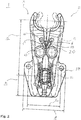
- FIG. 2 a technical drawing of a gripping device with the gripping arms according to the invention Fig. 1 shown.
- control cam 11 is shown as a control means, in particular a locking means, which is rotatably mounted in a carrier element 18 and is arranged between the end sections, in particular the spring bars, of the pair of gripper arms.
- the gripping arms 2, 3 are rotatably mounted by means of fastening screws and fastened to the carrier element 18. Both the gripping position and the opening position of the gripping device are shown in the drawing.
- the spring tongues 6 of the gripping arms 2, 3 act on one another and thereby bend elastically or exert a force on one another due to the deflection.
- Fig. 3 is a perspective view of the gripping device Fig. 2 , both in an exploded view and in an assembled state.
- the recesses in which the control cam 11 and the fastening screws 20 can be inserted can additionally be seen in the carrier element 18.
- the fastening screws 20 have a thread on the lower part for fastening in the carrier element 18, a cylindrical shape in the central region as a bearing for the bore of the gripping arm 2, 3 and a screw head on the upper part.
- Fig. 4 shows a representation of the spring tongues 6, 6 'as an advantageous embodiment from a gripping arm 2 according to the invention Fig. 1 or. Fig. 2 and a gripping arm 3 of opposite design Fig. 2 which are suitable to come into active engagement in the form of a cross overlay. Due to the active engagement, the spring tongues 6, 6 'are always connected to one another and can act as closing means. A notch / notch 19, 19 'is formed in each of the end pieces 13, 13' of the spring tongues 6, 6 '.
- the width of the notch 19 in the direction of the length of the spring tongue web 15 corresponds to the thickness / depth of the end piece 13 'or of the notch 19' perpendicular to the direction of the length of the spring tongue web 15 '(see dashed lines running in parallel). The same applies in reverse for the width of the notch 19 '. Since the spring tongues 6, 6 'are identical and mirror-inverted to each other and the notches 19, 19' are formed in the same position in the spring tongue 6, 6 ', the thickness and width of the notches 19, 19' are the same in this case or the base of the notches 19, 19 'is square. Dimensions in Fig. 1 Dimensions in Fig.
Description
Die vorliegende Erfindung betrifft einen Greifarm für eine Vorrichtung zum Greifen, Halten und Führen von insbesondere flaschenartigen Behältern sowie eine Greifvorrichtung mit derartigen Greifarmen. Hierbei bildet der Greifarm einen Teil einer Vorrichtung, welche zum Bewegen eines Greifabschnitts des Greifarms von einer Öffnungsstellung in eine Greifstellung oder umgekehrt ein Steuermittel aufweist. Der Greifarm selbst weist eine Bohrung zur Lagerung eines Lagerbolzens zum schwenkbaren Befestigen des Greifarms in der Vorrichtung, und einen Kraftspeicher zum Bewegen des Greifabschnitts des Greifarms von der Greifstellung in die Öffnungsstellung oder umgekehrt auf.The present invention relates to a gripping arm for a device for gripping, holding and guiding, in particular bottle-like containers, and a gripping device with such gripping arms. Here, the gripping arm forms part of a device which has a control means for moving a gripping section of the gripping arm from an open position to a gripping position or vice versa. The gripping arm itself has a bore for mounting a bearing pin for pivotably fastening the gripping arm in the device, and an energy store for moving the gripping section of the gripping arm from the gripping position to the open position or vice versa.
Unter dem Begriff "Behälter" sind nachstehend insbesondere, aber nicht ausschließlich flaschenartige Behälter zu verstehen, also zum Beispiel Getränkeflaschen aus Glas oder Kunststoff, aber auch Fläschchen für Arzneimittel oder Parfüm. Unter den Begriff fallen ebenfalls andere Glas- oder Kunststoffbehälter, die ähnlich zu einer Flasche insbesondere einen Hals oder eine zur Öffnung verjüngende Struktur aufweisen.The term “container” is to be understood in the following in particular, but not exclusively, as bottle-like containers, for example beverage bottles made of glass or plastic, but also bottles for pharmaceuticals or perfume. The term also includes other glass or plastic containers which, similar to a bottle, in particular have a neck or a structure tapering towards the opening.
Ein solcher Greifarm ist dem Grunde nach aus dem Stand der Technik bekannt und wird bei der fließbandtechnischen Bearbeitung von Behältern verwendet. Insbesondere beim Reinigen, Befüllen oder Verschließen werden die Behälter bei einer Eingangsstation mittels einer Greifvorrichtung mit mindestens einem Greifarmpaar ergriffen und zur nächsten Station im Prozess transportiert.Such a gripper arm is basically known from the prior art and is used in the assembly line processing of containers. In particular when cleaning, filling or closing, the containers are used by one Entrance station gripped by means of a gripping device with at least one pair of gripping arms and transported to the next station in the process.
Eine solche Vorrichtung ist beispielsweise in der Patentanmeldeschrift
Eine ähnliche und ebenfalls bekannte Greifvorrichtung wird in der Deutschen Gebrauchsmusterschrift
Allerdings bringen die zuvor genannten Greifvorrichtungen des Standes der Technik in einer nicht staubfreien Umgebung Hygieneprobleme mit sich, was sich insbesondere beim Einsatz in hygienesensitiven Bereichen wie dem Abfüllen von Getränken, Säften oder Babynahrung als nachteilig erweist. Denn die vorstehend beschriebenen Einzelteile eines aus dem Stand der Technik bekannten Greifarms, insbesondere die Spiralfeder und die Blattfeder mit ihren jeweiligen Befestigungsmitteln, aber auch die einzusetzenden Magnete, sammeln Staub und/oder andere Verschmutzungen an, wodurch sich unerwünschte Keime festsetzen können.However, the above-mentioned gripping devices of the prior art bring with them hygiene problems in a non-dust-free environment, which proves to be disadvantageous in particular when used in hygiene-sensitive areas such as the filling of drinks, juices or baby food. This is because the above-described individual parts of a gripper arm known from the prior art, in particular the spiral spring and the leaf spring with their respective fastening means, but also the magnets to be used, collect dust and / or other contaminants, as a result of which undesirable germs can become lodged.
Ebenso ist die Anzahl der Einzelteile des Greifarms sowohl für die Herstellung und Montage, als auch für die Wartung und Reinigung von Nachteil. Hierbei müssen logistische Aufträge und Lieferungen erfolgen, um alle Komponenten zu erhalten und den Greifarm fertigstellen bzw. warten zu können. Außerdem bedarf es zusätzlicher Montageschritte, um den Greifarm zusammenzusetzen.Likewise, the number of individual parts of the gripper arm is disadvantageous both for manufacture and assembly, and for maintenance and cleaning. Here, logistical orders and deliveries must be made in order to receive all components and to be able to complete or maintain the gripper arm. In addition, additional assembly steps are required to assemble the gripper arm.
Der Erfindung liegt die Aufgabe zugrunde, einen Greifarm bereitzustellen, der ohne weiteres ausreichend frei von Verschmutzungen und Keimen gehalten werden kann und so wenige Einzelteile wie möglich aufweist.The invention has for its object to provide a gripping arm that can be easily kept free of dirt and germs and has as few individual parts as possible.
Die gestellte Aufgabe wird bei einem eingangs genannten Greifarm dadurch gelöst, dass der Kraftspeicher eine integral am Greifarm ausgebildete und elastisch auslenkbare Federzunge aufweist, die mit einer Federzunge eines gegengleich ausgebildeten Greifarms der Vorrichtung in Wirkeingriff steht oder kommt.The object is achieved in a gripper arm mentioned at the outset in that the energy store has an integrally formed and elastically deflectable spring tongue on the gripper arm, which is or comes into active engagement with a spring tongue of an oppositely configured gripper arm of the device.
Unter dem Begriff "integral" versteht man insbesondere dazugehörend oder zusammenhängend. Unter dem Begriff "Federzunge" versteht man insbesondere, aber nicht ausschließlich ein elastisches oder gefedertes Endstück, das auf Grund seiner materiellen und/oder strukturellen Beschaffenheit entlang mindestens eines Teils seiner Länge biegbar ist und im Falle keiner äußeren Krafteinwirkung wieder in eine Ausgangs-/Grundposition zurückgeht bzw. -fällt. Hierbei ist ein Ende der Federzunge frei bzw. ungebunden ausgebildet und das gegenüberliegende Ende an einem Gegenstand, in diesem Fall dem Greifarm, befestigt oder ausgebildet. Vorzugsweise hat die Federzunge lediglich einen Biegefreiheitsgrad, d.h. die Federzunge lässt sich im Wesentlichen nur entlang einer Ebene biegen. Dabei ist die Federzunge vorzugsweise derart beschaffen, dass unabhängig vom Ort der Krafteinwirkung an der Federzunge im Wesentlichen die komplette Breite gleichmäßig ausgelenkt wird und somit keine, zumindest keine beträchtliche, Verdrehung entlang der Achse bzw. der Länge der Federzunge erfolgt. Dadurch agiert die als Kraftspeicher fungierende Federzunge bei einem Wirkeingriff stabiler und wirkt im gespannten oder ausgelenktem Zustand eine Kraft auf oder vom Greifarm weg.The term "integral" means in particular belonging or connected. The term "spring tongue" means in particular but not exclusively an elastic or spring-loaded end piece, which due to its material and / or structural nature can be bent along at least part of its length and, in the case of no external force, returns or falls back to a starting / basic position. In this case, one end of the spring tongue is designed free or unbound and the opposite end is fastened or designed to an object, in this case the gripping arm. The spring tongue preferably has only one degree of freedom of bending, ie the spring tongue can essentially only be bent along one plane. The spring tongue is preferably designed such that, regardless of the location of the force acting on the spring tongue, essentially the entire width is deflected uniformly and thus there is no, at least no significant, rotation along the axis or the length of the spring tongue. As a result, the spring tongue, which acts as an energy store, acts more stably in the event of an active intervention and acts in a tensioned or deflected state on or away from the gripping arm.
Die bei herkömmlichen Greifarmen regelmäßig zum Einsatz kommenden separaten Federn oder Magnetpaare entfallen somit, wodurch eine wesentlich hygienischere, einteilige Bauform des Greifarms ohne Verschmutzungen anziehende Querbohrungen, Sacklöchern oder ähnlicher Aufnahmen für Kraftspeicher erzielbar ist. Damit einher geht eine erhebliche Reduzierung der Herstellungskosten, der Wartungs- und Reparaturanfälligkeit, da die herkömmlichen Kraftspeicher mit den notwendigen Montageschritten am Greifarm nicht mehr benötigt werden. Im Ergebnis werden die Anzahl der Bauteile eines Greifarms und die Ansatzflächen für Keime und Verschmutzungen wie z.B. Oberflächenvertiefungen und Schlitze erheblich reduziert.The separate springs or magnet pairs that are regularly used in conventional gripper arms are therefore no longer required, which means that a much more hygienic, one-piece design of the gripper arm can be achieved without cross holes, blind holes or similar receptacles for energy stores that attract dirt. This goes hand in hand with a considerable reduction in manufacturing costs and the need for maintenance and repairs, since conventional energy storage devices with the necessary assembly steps on the gripper arm are no longer required. As a result, the number of components of a gripper arm and the attachment areas for germs and dirt such as Surface recesses and slots significantly reduced.
In einer vorteilhaften Ausgestaltung der Erfindung weist die Federzunge ein Endstück und einen sich zum Endstück verjüngenden Federzungensteg auf. Dadurch ist die Federzunge bei einer Biegung ausreichend flexibel und gleichzeitig stabil an dem Greifarm angeordnet bzw. ausgebildet, um frühzeitige Risse oder Brüche im Material zu vermeiden. Des Weiteren übernimmt der Federzungensteg aufgrund seiner elastischen Biegefähigkeit hauptsächlich die Funktion des Kraftspeichers, während das Endstück stabil und/oder steif genug ausgebildet ist, um die Kraft gerichtet und ohne Schwankung auszuüben bzw. zu übertragen.In an advantageous embodiment of the invention, the spring tongue has an end piece and a spring tongue web tapering towards the end piece. As a result, the spring tongue is sufficiently flexible and at the same time stably arranged or formed on the gripping arm in order to avoid premature cracks or breaks in the material. Furthermore, due to its elastic bending ability, the spring tongue web mainly takes over the function of the energy store, while the end piece is designed to be stable and / or stiff enough to exert or transmit the force in a directed manner and without fluctuation.
Damit die Federzunge als Schließmittel für das Greifarmpaar dienen kann, müssen die Federzungen der beiden Greifarme miteinander verbunden werden. Hierzu weist die Federzunge, insbesondere deren Endstück, vorteilhafterweise einen Schlitz (oder auch Kerbe/Einschnitt) auf, der ausgebildet ist, mit einer Federzunge, insbesondere deren Schlitz, eines gegengleich ausgebildeten Greifarms der Greifvorrichtung in Wirkeingriff zu kommen. Der Wirkeingriff ist hierbei insbesondere als Kreuzüberblattung ausbildbar.So that the spring tongue can serve as a closing means for the pair of gripper arms, the spring tongues of the two gripper arms must be connected to one another. For this the spring tongue, in particular its end piece, advantageously has a slot (or notch / notch) which is designed to come into active engagement with a spring tongue, in particular its slot, of a gripping arm of the gripping device of opposite design. The active intervention can be configured in particular as a cross-overlay.
Es hat sich ebenfalls als vorteilhaft herausgestellt, wenn die Federzunge in axialer Richtung der Bohrung im Wesentlichen die gleiche Breite wie der Greifarm aufweist. Dadurch können die Federzungen nicht ohne weiteres voneinander abrutschen und ihren Wirkeingriff verlieren.It has also proven to be advantageous if the spring tongue has essentially the same width as the gripping arm in the axial direction of the bore. As a result, the spring tongues cannot easily slide off one another and lose their operative engagement.
Vorzugsweise ist die Federzunge, insbesondere deren Endstück, im entspannten oder nicht ausgelenkten Zustand von einer dem gegengleich ausgebildeten Greifarm zugewandten Seitenfläche des Greifarms beabstandet. Diese vorteilhafte Ausgestaltung erlaubt es, dass die Federzunge als Öffnungsmittel dienen kann, da sie zum Greifarm hin, insbesondere zu dessen Seitenfläche, ausgelenkt werden kann.In the relaxed or undeflected state, the spring tongue, in particular its end piece, is preferably spaced apart from a side face of the gripping arm facing the gripping arm of opposite design. This advantageous embodiment allows the spring tongue to serve as an opening means, since it can be deflected towards the gripping arm, in particular towards its side surface.
Um verschiedene Steuermittel verwenden zu können, die entweder am Vorderabschnitt oder am Endabschnitt des Greifarms wirken können, ist der Kraftspeicher zwischen der Bohrung und dem Greifabschnitt und/oder zwischen der Bohrung und einem Endabschnitt des Greifarms ausgebildet.In order to be able to use various control means which can act either on the front section or on the end section of the gripping arm, the energy accumulator is formed between the bore and the gripping section and / or between the bore and an end section of the gripping arm.
Die Herstellung eines Gegenstands aus Kunststoff ist günstig und schnell. Daher ist der Greifarm vorteilhafterweise einstückig aus insbesondere faserverstärktem Kunststoff gefertigt und somit sofort in einer Greifvorrichtung einsetzbar. Die Faserverstärkung ermöglicht einen Faser-Kunststoff-Verbund aus hoher spezifischer Steifigkeit und Festigkeit. Herkömmliche Greifarme bestehen aus Edelstahl und sind deshalb relativ teuer. Darüber hinaus hat sich im Betrieb der in Rede stehenden Vorrichtungen gezeigt, dass sich die metallischen Greifarme gelegentlich verbiegen, was zum einen beim Betrieb der Vorrichtung schwer erkennbar ist und zum anderen zu Beschädigungen der zu greifenden und transportierenden Behälter und/oder der gegenüberliegenden Greifarme, welche den Behälter übergeben bzw. übernehmen, und/oder anderer Armaturen führen kann. Werden die Greifarme hingegen aus Kunststoff gefertigt, lassen sie sich sehr günstig als Wegwerfartikel im Spritzgussverfahren herstellen. Des Weiteren weist Kunststoff für diesen Einsatz bessere Eigenschaften gegenüber Edelstahl auf, so dass eine Überbeanspruchung des Greifarms nicht zum Verbiegen, sondern zum sofortigen Bruch führt, was keine Folgebeschädigung der Flasche nach sich zieht und ein sofortiges Erkennen des überbeanspruchten Greifarms ermöglicht. Dann kann der Greifarm aufgrund seiner einstückigen Ausbildung sehr rasch und kostengünstig ersetzt werden. Ebenso zeigt Kunststoff im Gegensatz zu herkömmlich verwendetem Metall bzw. Edelstahl kaum Verschleißerscheinungen bei der Reinigung mit Wasser. Durch einen aus Kunststoff geformten Greifarm entsteht ein leicht austauschbares Produkt, dass nach seiner Abnutzung ohne Probleme entfernt und ohne große Kosten oder Lieferzeiten und ohne großen Stillstand der Anlage, deren Bestandteil die Greifvorrichtung ist, ersetzt werden kann.The manufacture of a plastic item is inexpensive and quick. Therefore, the gripping arm is advantageously made in one piece from, in particular, fiber-reinforced plastic and can therefore be used immediately in a gripping device. The fiber reinforcement enables a fiber-plastic composite of high specific rigidity and strength. Conventional gripper arms are made of stainless steel and are therefore relatively expensive. In addition, it has been shown in the operation of the devices in question that the metallic gripping arms occasionally bend, which is difficult to recognize on the one hand during operation of the device and on the other hand, which damage the containers to be gripped and transported and / or the opposite gripping arms hand over or take over the container and / or other fittings. If, on the other hand, the gripper arms are made of plastic, they can be manufactured very cheaply as disposable items by injection molding. In addition, plastic has better properties than stainless steel for this application, so that an overloading of the gripper arm does not cause it to bend, but rather to break immediately leads, which does not result in consequential damage to the bottle and enables immediate identification of the overstressed gripper arm. Then the gripper arm can be replaced very quickly and inexpensively due to its one-piece design. In contrast to conventionally used metal or stainless steel, plastic also shows hardly any signs of wear when cleaning with water. A gripping arm molded from plastic creates an easily replaceable product that can be easily removed after its wear and tear and can be replaced without great costs or delivery times and without major downtime of the system, of which the gripping device is a component.
In einer weiteren vorteilhaften Ausgestaltung weist der Greifabschnitt ein sich von der Unterseite zur Oberseite des Greifarms verjüngendes und/oder stufenförmiges Profil auf. Dies hat den Vorteil, Flaschenhälse und insbesondere Flaschen unterhalb deren Neckring oder Flaschenhalskragen zu greifen und somit stabil transportieren zu können.In a further advantageous embodiment, the gripping section has a tapering and / or stepped profile tapering from the underside to the top of the gripping arm. This has the advantage of being able to grip bottle necks and in particular bottles below their neck ring or bottle neck collar and thus to be able to transport them stably.
Vorzugsweise weist der Greifarm einen integral am Greifarm ausgebildeten und elastisch auslenkbaren Federsteg zum Kompensieren der Kraft und/oder Auslenkung durch das Steuermittel auf, wobei der Federsteg mit dem Greifarm eine geschlossen umlaufende Ausnehmung bildet.Preferably, the gripping arm has an integrally formed and elastically deflectable spring bar for compensating the force and / or deflection by the control means, the spring bar forming a closed circumferential recess with the gripping arm.
Die Erfindung betrifft ebenfalls eine Greifvorrichtung mit mindestens einem Paar aus einem Greifarm gemäß einer der zuvor genannten Ansprüche und einem gegengleich ausgebildeten Greifarm und mit einem Steuermittel zum Bewegen eines Greifabschnitts des Greifarms von einer Öffnungsstellung in eine Greifstellung oder umgekehrt.The invention also relates to a gripping device with at least one pair of a gripping arm according to one of the aforementioned claims and a gripping arm of opposite design and with a control means for moving a gripping section of the gripping arm from an open position to a gripping position or vice versa.
Im Folgenden werden weitere, vorteilhafte Ausgestaltungen der Ausführungsformen des Greifarms und der Greifvorrichtung erläutert:
Das Steuermittel/-einheit kann, wie zuvor beschrieben, als Steuernocken zwischen einem Greifarmpaar ausgebildet sein. Dabei fungiert es abhängig von seiner Positionierung entweder als Öffnungsmittel (Positionierung zwischen Bohrung und Greifabschnitt) oder als Schließmittel (Positionierung zwischen Bohrung und Endabschnitt) der Greifvorrichtung.Further advantageous configurations of the embodiments of the gripping arm and the gripping device are explained below:
As described above, the control means / unit can be designed as a control cam between a pair of gripper arms. Depending on its positioning, it acts either as an opening means (positioning between the hole and the gripping section) or as a closing means (positioning between the hole and the end section) of the gripping device.
Alternativ kann der Greifarm direkt über den Lagerbolzen angesteuert werden, wenn der Greifarm verdrehsicher auf dem Lagerbolzen angeordnet ist. Hierzu ist am oberen oder unteren Ende des drehbar gelagerten Lagerbolzens ein Hebel ausgebildet, durch dessen Betätigung bzw. Drehung gleichzeitig der Greifarm geschwenkt werden kann. Der gegengleich ausgebildete Greifarm wird dabei mit einem eigenen Hebel oder mit einem Verzahnungselement des Lagerbolzens, das mit einem Verzahnungselement des anderen Lagerbolzens in Wirkeingriff steht, synchron angesteuert.Alternatively, the gripper arm can be controlled directly via the bearing pin if the gripper arm is arranged on the bearing pin in a manner that prevents it from rotating. This is At the upper or lower end of the rotatably mounted bearing pin, a lever is formed, by the actuation or rotation of which the gripping arm can be pivoted at the same time. The oppositely designed gripping arm is controlled synchronously with its own lever or with a toothing element of the bearing pin, which is in operative engagement with a toothing element of the other bearing pin.
Abhängig davon, ob das Steuermittel als Öffnungsmittel oder Schließmittel ausgebildet ist, fungiert der Kraftspeicher umgekehrt als Schließmittel oder Öffnungsmittel, um die Greifvorrichtung automatisch in eine Ausgangsstellung zu bringen. Die Ausgangsstellung kann abhängig von der Funktion des Kraftspeichers entweder die Greifstellung oder die Öffnungsstellung sein.Depending on whether the control means is designed as an opening means or a closing means, the energy store functions in reverse as a closing means or opening means in order to automatically bring the gripping device into a starting position. The starting position can be either the gripping position or the open position depending on the function of the energy accumulator.
Die Federzunge kann geradlinig oder gebogen ausgebildet und entweder in die Richtung des Endabschnitts oder des Greifabschnitts des Greifarms gerichtet sein. Da z.B. in der Greifstellung die Federzungen, insbesondere deren Endstück, im Wesentlichen am Greifarm anliegen, kann die elastische Federkraft dadurch erhöht werden, dass die Federzunge im nicht ausgelenkten bzw. nicht verbogenen Zustand stärker von dem Greifarm weggerichtet ist oder das Endstück von der Seitenfläche des Greifarms weiterweg beabstandet ist.The spring tongue can be rectilinear or curved and can be directed either in the direction of the end section or the gripping section of the gripping arm. Because e.g. In the gripping position, the spring tongues, in particular their end piece, essentially rest on the gripping arm, the elastic spring force can be increased in that the spring tongue is directed more away from the gripping arm in the non-deflected or non-bent state or the end piece continues away from the side surface of the gripping arm is spaced.
Anhand der folgenden Zeichnungen wird ein bevorzugtes Ausführungsbeispiel des erfindungsgemäßen Greifarms beschrieben und im Detail erläutert. Es zeigen
- Fig. 1
- eine technische Zeichnung die Oberseite eines erfindungsgemäßen Greifarmes;
- Fig. 2
- eine technische Zeichnung einer Greifvorrichtung mit den erfindungsgemäßen Greifarmen aus
Fig. 1 ; - Fig. 3
- eine perspektivische Ansicht der Greifvorrichtung aus
Fig. 2 , sowohl in einer Explosionsansicht als auch in einem zusammengesetzten Zustand; und - Fig. 4
- eine Darstellung der Federzungen in einer weiteren Ausgestaltung von einem erfindungsgemäßen Greifarm aus
Fig. 1 bzw.Fig. 2 und einem gegengleich ausgebildeten Greifarm ausFig. 2 , die für eine Kreuzüberblattung geeignet sind.
- Fig. 1
- a technical drawing the top of a gripper arm according to the invention;
- Fig. 2
- a technical drawing of a gripping device with the gripping arms according to the invention
Fig. 1 ; - Fig. 3
- a perspective view of the gripping device
Fig. 2 , both in an exploded view and in an assembled state; and - Fig. 4
- a representation of the spring tongues in a further embodiment of a gripping arm according to the invention
Fig. 1 or.Fig. 2 and a gripping arm of opposite designFig. 2 that are suitable for a cross overlay.
In der perspektivischen Ansicht von
Der Greifarm 2 ist vorzugsweise länglich geformt und ist in einen Vorderabschnitt 12 und einen Endabschnitt 14 unterteilt. Der Greifarm 2 ist für eine Vorrichtung zum Greifen, Halten und Führen von insbesondere flaschenartigen Behältern vorgesehen, welche zum Bewegen eines Greifabschnitts 5 des Greifarms 2 von einer Öffnungsstellung in eine Greifstellung einen - hier nicht dargestellten - drehbar gelagerten Steuernocken aufweist. Zwischen den beiden Abschnitten 12 und 14 ist eine Bohrung 10 zur Lagerung eines - hier nicht dargestellten - Lagerbolzens zum schwenkbaren Befestigen des Greifarms 2 in der Vorrichtung angeordnet bzw. liegt auf der Grenze zwischen beiden Abschnitten. Im Vorderabschnitt 12 ist eine Federzunge 6 als ein Öffnungsmittel zum Bewegen des Greifabschnitts 5 des Greifarms 2 von der Greifstellung in die Öffnungsstellung ausgebildet. Zwischen der Federzunge 6 und dem Greifarm 2, insbesondere dem Vorderabschnitt 12, ist eine Ausnehmung 8 ausgebildet, die zum Endstück der Federzunge 6 hin zur Seite des Greifarms 2 offen ist. Diese Öffnung hat eine Breite, die im Wesentlichen die maximale Auslenkung der Federzunge 2 zum Greifarm 2 definiert. Durch das Zusammenwirken des Greifabschnitts 5 mit einem Greifabschnitt eines - hier nicht dargestellten - gegengleich ausgebildeten zweiten Greifarms wird der Greifvorrichtung das Greifen und Halten eines Behälters ermöglicht. Im Endabschnitt 14 ist ein Federsteg 16 zum Abfedern und Ausgleichen der durch den Steuernocken auf den Greifarm 2 ausgeübten Kraft und/oder Auslenkung ausgebildet. Dabei ist der Federsteg 16 integral in einem Endabschnitt 14 des Greifarmkörpers ausgebildet. Der Federsteg 16 bildet mit dem Endabschnitt 14 eine geschlossene Ausnehmung 9, welche dem Federsteg 16 Raum für den erforderlichen Federweg bzw. eine elastische Auslenkung bietet. Der Greifarm 2 ist einstückig aus Kunststoff, vorzugsweise aus faserverstärktem Polyetheretherketon, gefertigt. Der Greifabschnitt 5 weist ein sich von einer Unterseite zu einer Oberseite des Greifarms 2 verjüngendes und stufenförmiges Profil auf. Die Bohrung 10 entspricht einer durchgehenden Bohrung von der Oberseite zur Unterseite des Greifarms 2, hat einen kreisförmigen Querschnitt und definiert eine Schwenkachse 4, die einer Symmetrieachse der Bohrung 10 entspricht. Dabei verläuft die Schwenkachse 4 senkrecht zur Oberseite und zur Unterseite. Der Greifarm 2 ist abgesehen von dem Öffnungsmittel 6 einstückig in einem Spritzgussverfahren aus Kunststoff herstellbar.The
In
Neben dem Greifarmpaar aus den Greifarmen 2, 3 wird der Steuernocken 11 als Steuermittel, insbesondere Schließmittel, gezeigt, der in einem Trägerelement 18 drehbar gelagert ist und zwischen den Endabschnitten, insbesondere den Federstegen, des Greifarmpaars angeordnet ist. Die Greifarme 2, 3 sind mittels Befestigungsschrauben drehbar gelagert und an dem Trägerelement 18 befestigt. In der Zeichnung wird sowohl die Greifstellung als auch die Öffnungsstellung der Greifvorrichtung gezeigt. In der Greifstellung wirken die Federzungen 6 der Greifarme 2, 3 aufeinander und verbiegen sich hierbei elastisch bzw. üben eine Kraft auf Grund der Auslenkung aufeinander aus. Sobald die Kraft des Steuernockens 11 nicht mehr auf den Endabschnitt der Greifarme 2, 3 wirkt, drücken sich die Federzungen 6, 6' voneinander weg, um ihre ursprünglich geradlinige Form wieder einnehmen zu können.In addition to the pair of gripper arms from the
In
- 11
- GreifvorrichtungGripping device
- 22nd
- GreifarmGripper arm
- 33rd
- Gegengleich ausgebildeter GreifarmGripping arm trained in the same way
- 44th
- Schwenkachse des GreifarmsSwivel axis of the gripper arm
- 55
- GreifabschnittGripping section
- 66
-
Federzunge von Greifarm 2Spring tongue of
gripper arm 2 - 6'6 '
-
Federzunge von Greifarm 3Spring tongue of
gripper arm 3 - 77
- SteuerachseControl axis
- 88th
- Ausnehmung für FederzungeRecess for spring tongue
- 99
- Ausnehmung für FederstegRecess for spring bar
- 1010th
- Bohrungdrilling
- 1111
- SteuernockenControl cam
- 1212th
- VorderabschnittFore section
- 1313
-
Endstück von Federzunge 6End piece of
spring tongue 6 - 13'13 '
- Endstück von Federzunge 6'End piece of spring tongue 6 '
- 1414
- EndabschnittEnd section
- 1515
-
Federzungensteg von Federzunge 6Spring tongue web of
spring tongue 6 - 15'15 '
- Federzungensteg von Federzunge 6'Spring tongue bridge from spring tongue 6 '
- 1616
- FederstegSpring bar
- 1717th
-
Seitenfläche von Greifarm 2Side surface of
gripper arm 2 - 1818th
- TrägerelementCarrier element
- 1919th
-
Kerbe/Einschnitt von Federzunge 6Notch / incision of
spring tongue 6 - 19'19 '
- Kerbe/Einschnitt von Federzunge 6'Notch / incision of spring tongue 6 '
- 2020
- BefestigungsschraubeMounting screw
Claims (10)
- A gripper arm (2) for a device for gripping, holding and guiding in particular bottle-like containers comprising a control means (11) for moving a gripping section (5) of the gripper arm from an open position into a gripping position or vice versa, having a bore (10) for the supporting of a bearing pin (20) for pivotably fixing the gripper arm (2) in the device, and an energy store for the moving of the gripping section (5) of the gripper arm from the gripping position into the open position or vice versa,
characterized in that
the energy store comprises a spring tongue (6) which is integrally formed on the gripper arm and elastically deflectable, which is or comes into operative engagement with a spring tongue (6') of a gripper arm (3) of a device of mirror-inverted configuration. - The gripper arm (2) according to claim 1,
characterized in that
the spring tongue (6) comprises an end piece (13) and a spring tongue bar (15) tapering to the end piece (13). - The gripper arm (2) according to claim 1 or 2,
characterized in that
the spring tongue (6), in particular its end piece (13), is configured so as to come into operative engagement with the spring tongue (6') of the mirror-inverted gripper arm (3), in particular its end piece, as a cross-lap joint. - The gripper arm (2) according to one of claims 1 to 3,
characterized in that
the spring tongue (6) has substantially the same width in the axial direction of the bore (10) as the gripper arm (2). - The gripper arm (2) according to one of claims 1 to 4,
characterized in that
the spring tongue (6), in particular its end piece (13) is distanced from a side surface (17) of the gripper arm (2) facing the mirror-inverted gripper arm (3) in the relaxed or non-deflected state. - The gripper arm (2) according to one of claims 1 to 5,
characterized in that
the energy store is formed between the bore (10) and the gripping section (5) and/or between the bore (10) and an end section (14) of the gripper arm (2). - The gripper arm (2) according to one of claims 1 to 6,
characterized in that
the gripper arm (2) is produced in one piece from in particular fiber-reinforced plastic. - The gripper arm (2) according to one of claims 1 to 7,
characterized in that
the gripping section (5) exhibits a tapered and/or stepped profile from the lower side to the upper side of the gripper arm (2). - The gripper arm (2) according to one of claims 1 to 8,
characterized in that
the gripper arm (2) comprises a spring bar (16) which is integrally formed on the gripper arm and elastically deflectable to compensate the force and/or deflection from the control means, wherein the spring bar (16) forms a closed circumferential recess (9) with the gripper arm (2). - A gripping device (1) having at least one pair of a gripper arm (2) according to one of the aforementioned claims and a gripper arm (3) of mirror-inverted configuration and a control means (11) for moving a gripping section (5) of each gripper arm (2, 3) from an open position into a gripping position or vice versa.
Applications Claiming Priority (1)
| Application Number | Priority Date | Filing Date | Title |
|---|---|---|---|
| PCT/EP2017/050383 WO2018130266A1 (en) | 2017-01-10 | 2017-01-10 | Gripper arm for containers and gripper device having such gripper arms |
Publications (2)
| Publication Number | Publication Date |
|---|---|
| EP3397577A1 EP3397577A1 (en) | 2018-11-07 |
| EP3397577B1 true EP3397577B1 (en) | 2020-08-05 |
Family
ID=57796342
Family Applications (1)
| Application Number | Title | Priority Date | Filing Date |
|---|---|---|---|
| EP17700320.9A Active EP3397577B1 (en) | 2017-01-10 | 2017-01-10 | Gripper arm for containers and gripper device having such gripper arms |
Country Status (7)
| Country | Link |
|---|---|
| US (1) | US10865055B2 (en) |
| EP (1) | EP3397577B1 (en) |
| JP (1) | JP6924835B2 (en) |
| CN (1) | CN110167855B (en) |
| BR (1) | BR112019014032B1 (en) |
| MX (1) | MX2019006846A (en) |
| WO (1) | WO2018130266A1 (en) |
Families Citing this family (8)
| Publication number | Priority date | Publication date | Assignee | Title |
|---|---|---|---|---|
| US11292709B2 (en) * | 2017-12-29 | 2022-04-05 | Coravin, Inc. | Beverage dispenser with container engagement features |
| US11795046B2 (en) * | 2015-11-25 | 2023-10-24 | Coravin, Inc. | Beverage dispenser with container engagement features |
| WO2018108370A1 (en) * | 2016-12-13 | 2018-06-21 | Tyrolon-Schulnig Gmbh | Modular bearing device for at least one pair of gripping arms, and method for assembling same |
| DE102018121092A1 (en) | 2018-08-29 | 2020-03-05 | Khs Gmbh | Device for gripping containers |
| DE102019131587A1 (en) * | 2019-11-22 | 2021-05-27 | Krones Aktiengesellschaft | Clamping device for holding a container |
| US11415449B2 (en) * | 2020-04-15 | 2022-08-16 | Worthington Cylinders Corporation | Cylinder attachment |
| IT202000018796A1 (en) * | 2020-07-31 | 2022-01-31 | Gd Spa | CLAMP DEVICE AND RELATED TRANSFER DEVICE |
| DE102021107294A1 (en) * | 2021-03-24 | 2022-09-29 | Krones Aktiengesellschaft | Clamping device and method for transporting a container |
Family Cites Families (15)
| Publication number | Priority date | Publication date | Assignee | Title |
|---|---|---|---|---|
| DE59601245D1 (en) * | 1995-05-13 | 1999-03-18 | Hermann Kronseder | Transport star for vessels |
| DE19542337A1 (en) | 1995-11-14 | 1997-05-15 | Hermann Kronseder | Transporting turntable for bottles |
| CN1163226A (en) * | 1996-03-13 | 1997-10-29 | 赫尔曼·克朗塞德 | Star conveyer for container |
| ATE227687T1 (en) * | 1996-03-13 | 2002-11-15 | Hermann Kronseder | TRANSPORT STAR FOR VESSELS |
| DE29712066U1 (en) * | 1997-07-09 | 1997-10-23 | Tretter Hermann | Gripping device for bottles |
| DE19740892A1 (en) * | 1997-09-17 | 1999-03-25 | Kettner Gmbh | Transport star for bottles with clamp device which can be quickly and reliably opened and closed |
| DE29915927U1 (en) * | 1999-09-10 | 2000-02-17 | Krones Ag | Bottle gripper |
| FR2838712B1 (en) * | 2002-04-22 | 2004-06-25 | Serac Group | DEVICE FOR PREVENTING RECIPIENTS WITH ECCENTRIC CONTROL |
| DE202005002924U1 (en) | 2005-02-23 | 2006-03-30 | Krones Ag | Clip gripper for a vascular transport system |
| DE102008032923A1 (en) * | 2008-07-12 | 2010-01-14 | Krones Ag | clip |
| DE102010009364B4 (en) * | 2010-02-25 | 2017-05-18 | Khs Gmbh | Bottle clamp with lock |
| DE102010052348A1 (en) * | 2010-11-25 | 2012-05-31 | Khs Gmbh | PET bottle-gripping device |
| KR101186256B1 (en) * | 2011-11-03 | 2012-09-27 | 피엔에스테크놀러지(주) | Apparatus for inspecting preform with gripper module |
| US8672376B1 (en) | 2012-11-16 | 2014-03-18 | Morrison Container Handling Solutions, Inc. | Gripping device |
| FR3004982B1 (en) * | 2013-04-24 | 2015-05-01 | Serac Group | DEVICE FOR HOLDING A CONTAINER COMPRISING A SPRING BLADE AND CONTAINER TREATING PLANT INCLUDING SUCH A DEVICE |
-
2017
- 2017-01-10 WO PCT/EP2017/050383 patent/WO2018130266A1/en active Application Filing
- 2017-01-10 EP EP17700320.9A patent/EP3397577B1/en active Active
- 2017-01-10 CN CN201780081818.2A patent/CN110167855B/en active Active
- 2017-01-10 BR BR112019014032-8A patent/BR112019014032B1/en active IP Right Grant
- 2017-01-10 JP JP2019537221A patent/JP6924835B2/en active Active
- 2017-01-10 MX MX2019006846A patent/MX2019006846A/en unknown
- 2017-01-10 US US16/474,869 patent/US10865055B2/en active Active
Non-Patent Citations (1)
| Title |
|---|
| None * |
Also Published As
| Publication number | Publication date |
|---|---|
| CN110167855B (en) | 2020-12-25 |
| JP2020505289A (en) | 2020-02-20 |
| BR112019014032A2 (en) | 2020-02-04 |
| BR112019014032B1 (en) | 2023-02-14 |
| JP6924835B2 (en) | 2021-08-25 |
| US20190322466A1 (en) | 2019-10-24 |
| MX2019006846A (en) | 2019-08-16 |
| EP3397577A1 (en) | 2018-11-07 |
| CN110167855A (en) | 2019-08-23 |
| US10865055B2 (en) | 2020-12-15 |
| WO2018130266A1 (en) | 2018-07-19 |
Similar Documents
| Publication | Publication Date | Title |
|---|---|---|
| EP3397577B1 (en) | Gripper arm for containers and gripper device having such gripper arms | |
| EP2769941B1 (en) | Gripper arm for containers and method for manufacturing this gripper arm | |
| EP2769942B1 (en) | Gripper arm for a gripping device and machine for transporting containers by means of such gripping arms | |
| EP3224165B1 (en) | Device for transporting containers | |
| EP1868746B1 (en) | Clamp for holding vessels | |
| DE102017105015B4 (en) | Gripping and transport device | |
| EP2143674B1 (en) | Clamp for holding containers | |
| EP2949608B1 (en) | Gripping arm for container, gripping device and transportation device | |
| EP1999048B1 (en) | Gripping element | |
| DE102014111564B4 (en) | Gripping arm for containers, control cams, storage unit and gripping device | |
| EP3239078B1 (en) | Device for regulating the height of a gripping and transport device for gripping, holding, guiding and transporting objects, in particular bottle-like containers | |
| EP3505469A2 (en) | Active clamping device | |
| EP2774876B1 (en) | Gripper device for gripping and holding bottles and transport device with such a gripping device | |
| EP3433189A1 (en) | Gripping apparatus and transporting device for transporting containers | |
| EP3755648B1 (en) | Gripper for a container transport system | |
| EP3433192B1 (en) | Bearing device | |
| EP2352692A1 (en) | Device for gripping pet bottles in bottle-filling systems or the like | |
| EP3433191B1 (en) | Carrying apparatus and cam control shaft for gripping devices | |
| EP3554976B1 (en) | Modular bearing device for at least one pair of gripping arms, and method for assembling same | |
| EP3887292A1 (en) | Device for gripping, retaining and guiding containers, and method for actuating such a device | |
| EP2774877B1 (en) | Gripper device for gripping and holding bottles, cans or similar fluid containers, transport star wheel with such a gripper device and manufacturing method | |
| EP2774878B1 (en) | Gripping arm for a gripping device and machine for transporting containers by means of such gripping arms | |
| EP3816076A1 (en) | Gripping device and transport device for gripping, holding and guiding in particular bottle-type containers | |
| DE4111475C2 (en) | Pneumatic tube rifle | |
| DE102017108930A1 (en) | Device for transporting containers |
Legal Events
| Date | Code | Title | Description |
|---|---|---|---|
| STAA | Information on the status of an ep patent application or granted ep patent |
Free format text: STATUS: UNKNOWN |
|
| STAA | Information on the status of an ep patent application or granted ep patent |
Free format text: STATUS: THE INTERNATIONAL PUBLICATION HAS BEEN MADE |
|
| PUAI | Public reference made under article 153(3) epc to a published international application that has entered the european phase |
Free format text: ORIGINAL CODE: 0009012 |
|
| STAA | Information on the status of an ep patent application or granted ep patent |
Free format text: STATUS: REQUEST FOR EXAMINATION WAS MADE |
|
| 17P | Request for examination filed |
Effective date: 20180802 |
|
| AK | Designated contracting states |
Kind code of ref document: A1 Designated state(s): AL AT BE BG CH CY CZ DE DK EE ES FI FR GB GR HR HU IE IS IT LI LT LU LV MC MK MT NL NO PL PT RO RS SE SI SK SM TR |
|
| AX | Request for extension of the european patent |
Extension state: BA ME |
|
| DAV | Request for validation of the european patent (deleted) | ||
| DAX | Request for extension of the european patent (deleted) | ||
| GRAP | Despatch of communication of intention to grant a patent |
Free format text: ORIGINAL CODE: EPIDOSNIGR1 |
|
| STAA | Information on the status of an ep patent application or granted ep patent |
Free format text: STATUS: GRANT OF PATENT IS INTENDED |
|
| INTG | Intention to grant announced |
Effective date: 20200424 |
|
| GRAS | Grant fee paid |
Free format text: ORIGINAL CODE: EPIDOSNIGR3 |
|
| GRAA | (expected) grant |
Free format text: ORIGINAL CODE: 0009210 |
|
| STAA | Information on the status of an ep patent application or granted ep patent |
Free format text: STATUS: THE PATENT HAS BEEN GRANTED |
|
| AK | Designated contracting states |
Kind code of ref document: B1 Designated state(s): AL AT BE BG CH CY CZ DE DK EE ES FI FR GB GR HR HU IE IS IT LI LT LU LV MC MK MT NL NO PL PT RO RS SE SI SK SM TR |
|
| REG | Reference to a national code |
Ref country code: GB Ref legal event code: FG4D Free format text: NOT ENGLISH |
|
| REG | Reference to a national code |
Ref country code: CH Ref legal event code: EP |
|
| REG | Reference to a national code |
Ref country code: AT Ref legal event code: REF Ref document number: 1298438 Country of ref document: AT Kind code of ref document: T Effective date: 20200815 |
|
| REG | Reference to a national code |
Ref country code: DE Ref legal event code: R096 Ref document number: 502017006554 Country of ref document: DE |
|
| REG | Reference to a national code |
Ref country code: IE Ref legal event code: FG4D Free format text: LANGUAGE OF EP DOCUMENT: GERMAN |
|
| REG | Reference to a national code |
Ref country code: LT Ref legal event code: MG4D |
|
| REG | Reference to a national code |
Ref country code: NL Ref legal event code: MP Effective date: 20200805 |
|
| PG25 | Lapsed in a contracting state [announced via postgrant information from national office to epo] |
Ref country code: PT Free format text: LAPSE BECAUSE OF FAILURE TO SUBMIT A TRANSLATION OF THE DESCRIPTION OR TO PAY THE FEE WITHIN THE PRESCRIBED TIME-LIMIT Effective date: 20201207 Ref country code: HR Free format text: LAPSE BECAUSE OF FAILURE TO SUBMIT A TRANSLATION OF THE DESCRIPTION OR TO PAY THE FEE WITHIN THE PRESCRIBED TIME-LIMIT Effective date: 20200805 Ref country code: SE Free format text: LAPSE BECAUSE OF FAILURE TO SUBMIT A TRANSLATION OF THE DESCRIPTION OR TO PAY THE FEE WITHIN THE PRESCRIBED TIME-LIMIT Effective date: 20200805 Ref country code: LT Free format text: LAPSE BECAUSE OF FAILURE TO SUBMIT A TRANSLATION OF THE DESCRIPTION OR TO PAY THE FEE WITHIN THE PRESCRIBED TIME-LIMIT Effective date: 20200805 Ref country code: FI Free format text: LAPSE BECAUSE OF FAILURE TO SUBMIT A TRANSLATION OF THE DESCRIPTION OR TO PAY THE FEE WITHIN THE PRESCRIBED TIME-LIMIT Effective date: 20200805 Ref country code: NO Free format text: LAPSE BECAUSE OF FAILURE TO SUBMIT A TRANSLATION OF THE DESCRIPTION OR TO PAY THE FEE WITHIN THE PRESCRIBED TIME-LIMIT Effective date: 20201105 Ref country code: BG Free format text: LAPSE BECAUSE OF FAILURE TO SUBMIT A TRANSLATION OF THE DESCRIPTION OR TO PAY THE FEE WITHIN THE PRESCRIBED TIME-LIMIT Effective date: 20201105 Ref country code: GR Free format text: LAPSE BECAUSE OF FAILURE TO SUBMIT A TRANSLATION OF THE DESCRIPTION OR TO PAY THE FEE WITHIN THE PRESCRIBED TIME-LIMIT Effective date: 20201106 Ref country code: ES Free format text: LAPSE BECAUSE OF FAILURE TO SUBMIT A TRANSLATION OF THE DESCRIPTION OR TO PAY THE FEE WITHIN THE PRESCRIBED TIME-LIMIT Effective date: 20200805 |
|
| PG25 | Lapsed in a contracting state [announced via postgrant information from national office to epo] |
Ref country code: IS Free format text: LAPSE BECAUSE OF FAILURE TO SUBMIT A TRANSLATION OF THE DESCRIPTION OR TO PAY THE FEE WITHIN THE PRESCRIBED TIME-LIMIT Effective date: 20201205 Ref country code: NL Free format text: LAPSE BECAUSE OF FAILURE TO SUBMIT A TRANSLATION OF THE DESCRIPTION OR TO PAY THE FEE WITHIN THE PRESCRIBED TIME-LIMIT Effective date: 20200805 Ref country code: RS Free format text: LAPSE BECAUSE OF FAILURE TO SUBMIT A TRANSLATION OF THE DESCRIPTION OR TO PAY THE FEE WITHIN THE PRESCRIBED TIME-LIMIT Effective date: 20200805 Ref country code: PL Free format text: LAPSE BECAUSE OF FAILURE TO SUBMIT A TRANSLATION OF THE DESCRIPTION OR TO PAY THE FEE WITHIN THE PRESCRIBED TIME-LIMIT Effective date: 20200805 Ref country code: LV Free format text: LAPSE BECAUSE OF FAILURE TO SUBMIT A TRANSLATION OF THE DESCRIPTION OR TO PAY THE FEE WITHIN THE PRESCRIBED TIME-LIMIT Effective date: 20200805 |
|
| PG25 | Lapsed in a contracting state [announced via postgrant information from national office to epo] |
Ref country code: DK Free format text: LAPSE BECAUSE OF FAILURE TO SUBMIT A TRANSLATION OF THE DESCRIPTION OR TO PAY THE FEE WITHIN THE PRESCRIBED TIME-LIMIT Effective date: 20200805 Ref country code: CZ Free format text: LAPSE BECAUSE OF FAILURE TO SUBMIT A TRANSLATION OF THE DESCRIPTION OR TO PAY THE FEE WITHIN THE PRESCRIBED TIME-LIMIT Effective date: 20200805 Ref country code: RO Free format text: LAPSE BECAUSE OF FAILURE TO SUBMIT A TRANSLATION OF THE DESCRIPTION OR TO PAY THE FEE WITHIN THE PRESCRIBED TIME-LIMIT Effective date: 20200805 Ref country code: SM Free format text: LAPSE BECAUSE OF FAILURE TO SUBMIT A TRANSLATION OF THE DESCRIPTION OR TO PAY THE FEE WITHIN THE PRESCRIBED TIME-LIMIT Effective date: 20200805 Ref country code: EE Free format text: LAPSE BECAUSE OF FAILURE TO SUBMIT A TRANSLATION OF THE DESCRIPTION OR TO PAY THE FEE WITHIN THE PRESCRIBED TIME-LIMIT Effective date: 20200805 |
|
| REG | Reference to a national code |
Ref country code: DE Ref legal event code: R097 Ref document number: 502017006554 Country of ref document: DE |
|
| PG25 | Lapsed in a contracting state [announced via postgrant information from national office to epo] |
Ref country code: AL Free format text: LAPSE BECAUSE OF FAILURE TO SUBMIT A TRANSLATION OF THE DESCRIPTION OR TO PAY THE FEE WITHIN THE PRESCRIBED TIME-LIMIT Effective date: 20200805 |
|
| PLBE | No opposition filed within time limit |
Free format text: ORIGINAL CODE: 0009261 |
|
| STAA | Information on the status of an ep patent application or granted ep patent |
Free format text: STATUS: NO OPPOSITION FILED WITHIN TIME LIMIT |
|
| PG25 | Lapsed in a contracting state [announced via postgrant information from national office to epo] |
Ref country code: SK Free format text: LAPSE BECAUSE OF FAILURE TO SUBMIT A TRANSLATION OF THE DESCRIPTION OR TO PAY THE FEE WITHIN THE PRESCRIBED TIME-LIMIT Effective date: 20200805 |
|
| 26N | No opposition filed |
Effective date: 20210507 |
|
| PG25 | Lapsed in a contracting state [announced via postgrant information from national office to epo] |
Ref country code: SI Free format text: LAPSE BECAUSE OF FAILURE TO SUBMIT A TRANSLATION OF THE DESCRIPTION OR TO PAY THE FEE WITHIN THE PRESCRIBED TIME-LIMIT Effective date: 20200805 Ref country code: MC Free format text: LAPSE BECAUSE OF FAILURE TO SUBMIT A TRANSLATION OF THE DESCRIPTION OR TO PAY THE FEE WITHIN THE PRESCRIBED TIME-LIMIT Effective date: 20200805 |
|
| REG | Reference to a national code |
Ref country code: CH Ref legal event code: PL |
|
| GBPC | Gb: european patent ceased through non-payment of renewal fee |
Effective date: 20210110 |
|
| PG25 | Lapsed in a contracting state [announced via postgrant information from national office to epo] |
Ref country code: LU Free format text: LAPSE BECAUSE OF NON-PAYMENT OF DUE FEES Effective date: 20210110 |
|
| REG | Reference to a national code |
Ref country code: BE Ref legal event code: MM Effective date: 20210131 |
|
| PG25 | Lapsed in a contracting state [announced via postgrant information from national office to epo] |
Ref country code: GB Free format text: LAPSE BECAUSE OF NON-PAYMENT OF DUE FEES Effective date: 20210110 Ref country code: LI Free format text: LAPSE BECAUSE OF NON-PAYMENT OF DUE FEES Effective date: 20210131 Ref country code: CH Free format text: LAPSE BECAUSE OF NON-PAYMENT OF DUE FEES Effective date: 20210131 |
|
| PG25 | Lapsed in a contracting state [announced via postgrant information from national office to epo] |
Ref country code: IE Free format text: LAPSE BECAUSE OF NON-PAYMENT OF DUE FEES Effective date: 20210110 |
|
| PG25 | Lapsed in a contracting state [announced via postgrant information from national office to epo] |
Ref country code: IS Free format text: LAPSE BECAUSE OF FAILURE TO SUBMIT A TRANSLATION OF THE DESCRIPTION OR TO PAY THE FEE WITHIN THE PRESCRIBED TIME-LIMIT Effective date: 20201205 |
|
| PG25 | Lapsed in a contracting state [announced via postgrant information from national office to epo] |
Ref country code: BE Free format text: LAPSE BECAUSE OF NON-PAYMENT OF DUE FEES Effective date: 20210131 |
|
| PGFP | Annual fee paid to national office [announced via postgrant information from national office to epo] |
Ref country code: FR Payment date: 20230124 Year of fee payment: 7 Ref country code: AT Payment date: 20230118 Year of fee payment: 7 |
|
| PGFP | Annual fee paid to national office [announced via postgrant information from national office to epo] |
Ref country code: IT Payment date: 20230120 Year of fee payment: 7 Ref country code: DE Payment date: 20230130 Year of fee payment: 7 |
|
| PG25 | Lapsed in a contracting state [announced via postgrant information from national office to epo] |
Ref country code: CY Free format text: LAPSE BECAUSE OF FAILURE TO SUBMIT A TRANSLATION OF THE DESCRIPTION OR TO PAY THE FEE WITHIN THE PRESCRIBED TIME-LIMIT Effective date: 20200805 |
|
| PG25 | Lapsed in a contracting state [announced via postgrant information from national office to epo] |
Ref country code: HU Free format text: LAPSE BECAUSE OF FAILURE TO SUBMIT A TRANSLATION OF THE DESCRIPTION OR TO PAY THE FEE WITHIN THE PRESCRIBED TIME-LIMIT; INVALID AB INITIO Effective date: 20170110 |
|
| PGFP | Annual fee paid to national office [announced via postgrant information from national office to epo] |
Ref country code: AT Payment date: 20240118 Year of fee payment: 8 |