EP3505469A2 - Active clamping device - Google Patents
Active clamping device Download PDFInfo
- Publication number
- EP3505469A2 EP3505469A2 EP18211558.4A EP18211558A EP3505469A2 EP 3505469 A2 EP3505469 A2 EP 3505469A2 EP 18211558 A EP18211558 A EP 18211558A EP 3505469 A2 EP3505469 A2 EP 3505469A2
- Authority
- EP
- European Patent Office
- Prior art keywords
- holding
- control
- arm
- arms
- active
- Prior art date
- Legal status (The legal status is an assumption and is not a legal conclusion. Google has not performed a legal analysis and makes no representation as to the accuracy of the status listed.)
- Pending
Links
Images


Classifications
-
- B—PERFORMING OPERATIONS; TRANSPORTING
- B25—HAND TOOLS; PORTABLE POWER-DRIVEN TOOLS; MANIPULATORS
- B25J—MANIPULATORS; CHAMBERS PROVIDED WITH MANIPULATION DEVICES
- B25J15/00—Gripping heads and other end effectors
- B25J15/0028—Gripping heads and other end effectors with movable, e.g. pivoting gripping jaw surfaces
-
- B—PERFORMING OPERATIONS; TRANSPORTING
- B25—HAND TOOLS; PORTABLE POWER-DRIVEN TOOLS; MANIPULATORS
- B25J—MANIPULATORS; CHAMBERS PROVIDED WITH MANIPULATION DEVICES
- B25J15/00—Gripping heads and other end effectors
- B25J15/02—Gripping heads and other end effectors servo-actuated
- B25J15/0206—Gripping heads and other end effectors servo-actuated comprising articulated grippers
- B25J15/0226—Gripping heads and other end effectors servo-actuated comprising articulated grippers actuated by cams
-
- B—PERFORMING OPERATIONS; TRANSPORTING
- B25—HAND TOOLS; PORTABLE POWER-DRIVEN TOOLS; MANIPULATORS
- B25J—MANIPULATORS; CHAMBERS PROVIDED WITH MANIPULATION DEVICES
- B25J9/00—Programme-controlled manipulators
- B25J9/0009—Constructional details, e.g. manipulator supports, bases
- B25J9/0015—Flexure members, i.e. parts of manipulators having a narrowed section allowing articulation by flexion
-
- B—PERFORMING OPERATIONS; TRANSPORTING
- B65—CONVEYING; PACKING; STORING; HANDLING THIN OR FILAMENTARY MATERIAL
- B65G—TRANSPORT OR STORAGE DEVICES, e.g. CONVEYORS FOR LOADING OR TIPPING, SHOP CONVEYOR SYSTEMS OR PNEUMATIC TUBE CONVEYORS
- B65G47/00—Article or material-handling devices associated with conveyors; Methods employing such devices
- B65G47/74—Feeding, transfer, or discharging devices of particular kinds or types
- B65G47/84—Star-shaped wheels or devices having endless travelling belts or chains, the wheels or devices being equipped with article-engaging elements
- B65G47/846—Star-shaped wheels or wheels equipped with article-engaging elements
- B65G47/847—Star-shaped wheels or wheels equipped with article-engaging elements the article-engaging elements being grippers
-
- B—PERFORMING OPERATIONS; TRANSPORTING
- B65—CONVEYING; PACKING; STORING; HANDLING THIN OR FILAMENTARY MATERIAL
- B65G—TRANSPORT OR STORAGE DEVICES, e.g. CONVEYORS FOR LOADING OR TIPPING, SHOP CONVEYOR SYSTEMS OR PNEUMATIC TUBE CONVEYORS
- B65G47/00—Article or material-handling devices associated with conveyors; Methods employing such devices
- B65G47/74—Feeding, transfer, or discharging devices of particular kinds or types
- B65G47/90—Devices for picking-up and depositing articles or materials
-
- B—PERFORMING OPERATIONS; TRANSPORTING
- B67—OPENING, CLOSING OR CLEANING BOTTLES, JARS OR SIMILAR CONTAINERS; LIQUID HANDLING
- B67C—CLEANING, FILLING WITH LIQUIDS OR SEMILIQUIDS, OR EMPTYING, OF BOTTLES, JARS, CANS, CASKS, BARRELS, OR SIMILAR CONTAINERS, NOT OTHERWISE PROVIDED FOR; FUNNELS
- B67C3/00—Bottling liquids or semiliquids; Filling jars or cans with liquids or semiliquids using bottling or like apparatus; Filling casks or barrels with liquids or semiliquids
- B67C3/02—Bottling liquids or semiliquids; Filling jars or cans with liquids or semiliquids using bottling or like apparatus
- B67C3/22—Details
- B67C3/24—Devices for supporting or handling bottles
- B67C3/242—Devices for supporting or handling bottles engaging with bottle necks
-
- B—PERFORMING OPERATIONS; TRANSPORTING
- B65—CONVEYING; PACKING; STORING; HANDLING THIN OR FILAMENTARY MATERIAL
- B65G—TRANSPORT OR STORAGE DEVICES, e.g. CONVEYORS FOR LOADING OR TIPPING, SHOP CONVEYOR SYSTEMS OR PNEUMATIC TUBE CONVEYORS
- B65G2201/00—Indexing codes relating to handling devices, e.g. conveyors, characterised by the type of product or load being conveyed or handled
- B65G2201/02—Articles
- B65G2201/0235—Containers
- B65G2201/0244—Bottles
- B65G2201/0247—Suspended bottles
Definitions
- the present invention relates to an active stapler for holding a container in a container treating apparatus and a container treating apparatus.
- active clip devices in which opening and closing of the respective holding sections of the clip device is actively performed by means of an actuator.
- Such active stapling devices serve, in particular, to enable a secure and gentle transfer of the respective containers from a preceding stapling device or an equally secure and container-friendly transfer of the containers to a subsequent stapling device To ensure stapling device.
- the active opening and closing of the respective clamping device increased friction on the respective container, which could for example lead to scratching of the container, and on the other hand, a predetermined holding force or clamping force can be adjusted, which complies with a predetermined tolerance range of the container dimension can be.
- Such active clamping devices are composed of a plurality of individual parts, for example clip arms, bushings, spring elements, biasing elements and corresponding connecting elements for securely connecting the aforementioned parts together.
- Such active clamping devices are therefore expensive to clean and have a correspondingly high production cost.
- a bottle gripper in which a gripping device is provided which has two gripping arms, which can be brought by means of a control cam in a holding position or a release position.
- the control cam interacts with a contact surface formed on each gripping arm and the abutment surface is formed as part of an elastic cushion which is arranged on the respective gripping arm.
- an active stapler for holding containers in which two gripper arms or staple arms with separate magnet assemblies are held in an open position.
- the bracket arms have rearwardly oriented locking levers which cooperate with a locking cam therebetween to bring the bracket arms from the open position to a closed position.
- the DE 10 2005 014 838 A1 shows an active stapling device for holding vessels with two staple arms which are movable for opening and closing relative to each other.
- one gripping arm of the clip is dimensionally stable and the other gripping arm is formed elastically.
- the gripping arms are biased by means of magnets arranged thereon in an open position and pivoted by means of a control cam in the closed position.
- an active clamping device for holding a container in a container treatment device, preferably for holding a beverage container at a neck portion having the features of claim 1.
- an active stapling apparatus for holding a container in a container treating apparatus, preferably for holding a beverage container in a neck portion, the active stapling apparatus comprising two staple arms each having a holding portion for holding the container to be held and a control portion for interacting with a control cam for actively moving the respective holding section, and comprising a biasing element for biasing the holding sections into a predetermined position.
- the clamp arms and the biasing element are integrally formed.
- clamp arms are connected to each other via the biasing member and the clamp arms and the biasing member formed integrally.
- an active clamping device can be provided with a particularly simple structure.
- an active clamping device with the features according to claim 1 can be particularly easily mounted on a container treatment device, since it does not have to be paid attention to a correct alignment of a plurality of individual parts to each other.
- the biasing member biases the staple arms in an opening position of the holding portions, the control portions being adapted to interact with the control cam to actively move the holding portions to a closed position.
- the clamping arms are always held in the open position and only when the control sections are actively moved by the control cam, for example by shifting the control sections out of their starting position, which is generated by pivoting the control cam, the clamping arms accordingly swing over and change to the closed position of the holding sections. If the control cam pivots back, the clamping arms are moved back into the opening position and held in the opening position due to the tension in the biasing element. Consequently, the clamping device always has an open position and only closes when the control sections are actively activated so that the clamping device only engages when it is actively activated for this purpose. Furthermore, by the displacement of the staple arms by the control cam a particularly secure holding the container can be achieved.
- the biasing member biases the staple arms in a closed position of the holding portions, the control portions being configured to interact with the control cam to actively move the holding portions to an open position.
- the clamping device always has a closed position and only opens when the control sections are actively activated, so that the clamping device is biased to grip the container. Since in container treatment plants usually in a large part of the range of movement of the clamp devices mounted on it to be treated containers are kept, can be dispensed with additional elements that otherwise to Holding the staplers in the closed position would be necessary. Correspondingly, control cams, which are required for actively opening the clamping devices, can only be provided in the regions in which the holding sections must be in the open position, for example for taking over or transferring a container.
- the staple arms can each be pivotable about a pivot axis. Due to the pivoting about the predetermined pivot axes, the opening position and the closing position can be taken particularly accurate.
- control sections are formed on the bracket arms in the form of a lever arm in each case, the interaction with the control cam can take place in a particularly simple manner.
- the clamping arms are pivoted about the pivot axes, so that the control cam relative to the clamp arms can have a fixedly positioned pivot point and is only to be rotated.
- the biasing element is designed as a bow spring, wherein the biasing element is preferably in the form of an extending from one clamp arm to the other bracket arm arc.
- Such a trained biasing element has an easy-to-clean shape, which can also be produced in a simple manner.
- a biasing force with which the biasing element biases the clamping arms particularly precisely predetermined and / or adapted to the particular application over a length of the bow spring or the bow and its profile.
- control sections and the biasing element are arranged according to a further preferred embodiment on a side opposite the holding portions of the clamp arms, it can be achieved that there are no disturbing the holding of the container parts in the region of the holding region. In addition, this reduces the likelihood that the control sections and the biasing element will reach a treatment medium, for example a filling product to be filled or filled into the container, onto the control sections and the biasing element.
- a treatment medium for example a filling product to be filled or filled into the container
- the holding sections are each arranged on one side of the clamp arms and arranged the control sections and / or the biasing member on the other side.
- At least the staple arms can have oblique surfaces for discharging liquids at their upper side.
- the oblique surfaces are preferably designed such that they enclose an angle of at least 3 ° with a plane oriented perpendicular to the pivot axes and / or with respect to an installation position of the stapling device on a container treatment device with a plane oriented perpendicular to the direction of gravitational acceleration at least 3 °.
- the inclined surfaces are preferably oriented in such a way that a sliding of particles is provided to the outside, thus away from a center or center plane of the stapler.
- at least the clip arms are each bevelled outwardly.
- the clamping arms each have mutually spaced support members for supporting the position of the clamping arms with respect to an installation position of the clamping device, preferably with respect to the pivot axes, against tilting, wherein preferably in each case a support element in the region of the respective pivot axis or to this around and / or a support element spaced from the respective pivot axis, preferably at one end of the control region, particularly preferably at a free end of the control arm formed as a support portion, and / or on the biasing member, is formed.
- the support elements preferably cooperate with corresponding support areas or support surfaces of the container treatment device, on which they are supported and thus support the clamping device with respect to the pivot axes against tilting.
- One yourself In a storage of the stapler on the pivot axes forming bearing clearance can thereby be almost or even completely prevented.
- control sections are elastically formed, wherein an elastic element, preferably in one piece, is preferably formed on a control arm forming the control section, and / or the control sections are formed elastically, wherein preferably the lever arm has a length and a profile, in such a way that the lever arm is preferably elastically deformable at least within a default range.
- control portion can follow the force applied by the control cam, and by means of the biasing force correspondingly a gentle application of this force to the holding portion via the clamping arms, enables a smooth yet reliable holding of the container.
- a gentle actuation of the clamping device can be achieved by means of the control cam, and on the other hand tolerances can be compensated in the container size over the elastic deformation capacity of the control sections achieved thereby, so that holding containers within a certain tolerance range is certainly possible. This also allows within certain limits the secure holding of incorrectly grasped containers.
- clamping arms preferably together with holding sections and control sections and the biasing element integrally formed as a 3D printing part or injection molded part, a simple and cost-effective production and at the same time a high freedom of form can be achieved.
- shape of the staple arms and the biasing element may be integrally formed and yet be adapted specifically to the requirements of the particular application.
- the clamping arms are preferably formed together with holding sections and control sections and the biasing element in one piece from a plastic, particularly preferably from a technical plastic or a high-performance plastic, most preferably made of PEEK.
- the active clamping device on the one hand have the required mechanical properties, for example, can be provided by the choice of plastic, preferably PA, in particular PA6 or PA66, or PEEK, a high durability against mechanical failure and sufficient bias.
- bearing bushes by means of which usually metal clamp arms are stored, are omitted because in the bracket arms itself due to the properties, in particular the sliding properties of the selected plastic, especially in PEEK, a bearing bore with the required tolerances and sliding properties can be introduced in a simple manner.
- an easy to be manufactured and easy to install and dismantle replacement part can be provided. Worn or old parts can be granulated and the resulting material used again for the production of new parts, so that the use of materials is reduced.
- an active clamping device formed in this way has a low weight.
- a stapling arm for holding a container in a stapling device, comprising a holding portion for holding the container to be held and a control portion for interacting with a cam for actively moving the holding portion.
- the stapling arm has at least two spaced supporting members for supporting the position of the stapling arm with respect to a pivoting axis of the stapling arm against tilting with respect to an installation position in the stapling device.
- the support elements preferably cooperate with corresponding support areas or support surfaces of a container treatment device, on which they are supported and thus support the staple arm or a stapling arm having stapling device with respect to the pivot axes against tilting.
- a bearing clearance forming in a bearing of the clamp arm on the pivot axis can thereby be almost or even completely prevented.
- an active clamp apparatus having a particularly simple structure can be provided.
- the clamp arm itself has the at least two spaced-apart support elements, the number of parts can be reduced in comparison to conventional clamping devices.
- separate units or devices for supporting the staple arms in the stapler and / or for supporting the container held in the stapler can be dispensed with, whereby assembly of the staple arms having stapler and / or container treatment device is less expensive and due to a reduction of Columns and cracks between the individual parts of the cleaning effort of such a clamping device and / or container treatment device is reduced.
- a stapling arm with the features according to claim 12 can be mounted particularly easily on a stapler and / or on a container treatment device, since care must be taken not to a correct alignment between the stapling arm and a separate support device to each other according to another preferred embodiment of the stapler in each case a support element in the region of the pivot axis and a support element spaced from the pivot axis, preferably at one end of the control region, particularly preferably formed at a free end of a control region designed as a support arm.
- control portion is formed elastically, wherein preferably an elastic element is formed on a control portion forming the lever arm and / or the control portion is formed elastically, wherein preferably the lever arm has a length and a profile, such that the lever arm preferably at least within a default range is elastically deformable.
- control portion can follow the force applied by the control cam, and by means of the biasing force correspondingly a gentle application of this force to the holding portion, enables a smooth and reliable holding of the container.
- a gentle actuation of the clamping device can be achieved by means of the control cam, and on the other hand tolerances can be compensated in the container size over the elastic deformation capacity of the control sections achieved thereby, so that holding containers within a certain tolerance range is certainly possible. This also allows within certain limits the secure holding of incorrectly grasped containers.
- clamp arm and at least one support element are integrally formed, a simple and cost-effective production and at the same time a high freedom of form can be achieved.
- the clamp arm and at least one support element are designed as 3D printing part or injection molded part, preferably made of a plastic, more preferably of a technical plastic or a high performance plastic, most preferably of PEEK.
- the stapling arm can have the required mechanical properties; for example, by choosing the plastic, preferably PA, in particular PA6 or PA66, or PEEK, a high durability against mechanical failure and sufficient preload can be provided.
- the clamp arm and / or the at least one support element made of the plastic an easy-to-manufacture and easy to assemble and disassemble exchange part can be provided. Worn or old parts can be granulated and the resulting material used again for the production of new parts, so that the use of materials is reduced.
- a trained clamp arm and / or a support element formed in this way due to the plastic, in particular in comparison to conventional Clamping devices with metal clamp arms and separate support devices, light weight.
- At least one support element may comprise a material other than the clamp arm, preferably a metal or a metal alloy and / or at least one support element may be provided as a separate part, preferably as a bearing bush.
- this is at least one support element having a different material than the staple arm, inserted into the staple arm and / or injected as an insert or reprinted three-dimensionally.
- an upper side of the stapling arm may have at least one inclined surface for discharging liquids.
- the oblique surfaces are preferably designed such that they enclose an angle of at least 3 ° with a plane oriented perpendicular to the pivot axes and / or with respect to an installation position of the stapling device on a container treatment device with a plane oriented perpendicular to the direction of gravitational acceleration at least 3 °.
- the oblique surfaces are preferably oriented in such a way that a sliding away of particles towards the outside, that is to say away from a center or median plane of a stapling device having at least one stapling arm, is provided.
- the bracket arms are then beveled outwardly.
- a container treatment apparatus for treating containers which has a staple carrier and at least one arranged thereon active stapling device according to one of the preceding embodiments and / or a stapling device with at least one stapling arm according to one of the preceding embodiments.
- bracket arms and the biasing member may be provided as individual parts in the aforementioned embodiments.
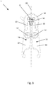
- FIG. 1 schematically shows a perspective top view of an active stapling device 1 for holding a container, not shown here.
- the active stapling device 1 has two staple arms 10 each having a holding portion 11 for holding the container to be held.
- the holding portion 11 typically engages a neck portion of the container to be held - for example, directly under a support ring.
- the active stapling device 1 can accordingly be advantageously provided for neck handling of containers in a container treatment device.
- the clamp arms 10 furthermore each have a control section 13 for interacting with a control cam (not shown here) for actively moving the clamp arms 10 and thus also the holding sections 11.
- Each clamp arm 10 has between the holding portion 11 and the control portion 13 has a bore 120 through which a pivot axis 12 extends. Accordingly, a pivoting about the pivot axis 12 can be achieved by a pivotable attachment of the clamp arms 10 to a container treatment device, for example by means of bolts guided in each case through the bores 120.
- the control sections 13 of the clamp arms 10 are each in the form of a lever arm 130 extending from the region of the pivot axis 12 to the rear, that is, with respect to the pivot axis 12, on the side opposite the holding section 11.
- the clamp arms 10 are connected to each other via a biasing member 14 in the form of an arc 140 extending from one clamp arm 10 to the other clamp arm 10.
- the clamp arms 10 and the biasing member 14 are integrally formed with each other.
- the arc 140 extends from the region of the pivot axes 12 to the rear and spans the lever arms 130th
- the biasing member 14 biases the clamp arms 10 in an opening position of the holding portions 11.
- the clamp arms 10 are held by the biasing member 14 in a position to each other, in which the holding portions 11 as in FIG. 1 shown occupy the opening position.
- annular support member 15 Around the holes 120 around an annular support member 15 is provided in each case. At a free end 132 of the respective lever arm 130, a further support element 15 'is provided in each case.
- the support members 15, 15 ' serve to support the position of the staple arms 10 with respect to an installation position of the stapler 1 on the container treatment apparatus, as further explained in detail FIG. 6 is described.
- the clamping arms 10 have on their upper side inclined surfaces 16 for the discharge of liquids. It is thereby achieved that particles and / or liquids impinging on the inclined surfaces 16 slide off the inclined surface 16 due to gravity and the formation of permanent contaminants such as a microbiological film is reduced or even completely prevented.
- the inclined surfaces 16 extend at least in the region of the active clamping device 1, in which they protrude into the treatment area of the container treatment device. This is typically the case at least in the region between the holding section 11 and the pivot axis 12. This is in the FIGS. 4 to 6 shown again below.
- the oblique surfaces extend substantially over the entire upper side of the clamp arms 10 and, to a large extent, also over the prestressing element 14 designed as a bow 140.
- FIG. 2 schematically shows a front view of the active stapler 1 from FIG. 1 , Clearly visible are the inclined surfaces 16 on the top of the staple arms 10th
- the oblique surfaces 16 are oriented in such a way that, viewed in relation to a central longitudinal plane or central axis 2, they slide outward of particles, thus from the Center longitudinal plane or central axis 2 of the stapler 1 is provided away.
- at least the tops of the staple arms 10 are each tapered outwardly.
- Excluded from the bevel are the support members 15, 15 'whose surfaces extend perpendicular to the pivot axes 12 to allow a stable abutment on a not shown mounting area of the container treatment device.
- FIG. 3 is a schematic plan view of the active stapling device 1 of the FIGS. 1 and 2 shown in interaction with a control cam 3.
- the control cam 3 extends with its greatest extent parallel to the central longitudinal axis 20 of the active clamping device 1.
- the biasing member 14 biases the clamp arms 10 in the opening position of the holding portions 11.
- the control cam 3 displaces the lever arms 130 outwardly from their position, so that the clamping arms 10 pivot about their respective pivot axis 12 and against the tension of the biasing member 14 in the closed position of the holding elements 11 are pivoted.
- the holding portions 11 are thus actively moved to its closed position. Consequently, by interacting with the control cam 3, an active gripping of a container to be held can take place.
- the control cam 3 is again in the in FIG. 3 to turn shown position. Due to the voltage generated by the giving away of the bracket arms 10 in the biasing member 14, the bracket arms 10 are returned to the in FIG. 3 pivoted position shown and the holding portions 11 moves back into its opening position accordingly.
- the clamp arms 10, together with their holding sections 11 and control sections 13 and the biasing element 14 are integrally formed from a plastic, in the present case PEEK. Due to the elasticity of the PEEK and the shape of the lever arms 130, in this case their length and their cross-sectional profile, the control sections 13 are formed elastically. In other words, the lever arms 130 are formed as elastic bending beams based on the elasticity of the PEEK. As a result, the control section 13 can follow the force applied by the control cam 3, and by means of the pretension, correspondingly a gentle application of this force via the clamp arms 10 to the holding section 11, enables a smooth and reliable holding of the container.
- a gentle actuation of the stapling device 1 can be achieved by means of the control cam 3, and on the other hand can be reached over the thereby achieved elastic deformation capacity of the control sections 13 tolerances are compensated in the container size, so that accordingly holding a container within a certain tolerance range is possible. This also allows within certain limits the safe and damage-free holding wrongly gripped or incorrectly oriented containers.
- the one-piece part which comprises the clamp arms 10 together with holding sections 11 and control sections 13 and the biasing element 14, is produced in the present case by means of a 3D printing method. Alternatively, it may for example also be produced by means of injection molding.
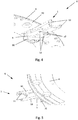
- FIG. 4 is a schematic side view from below of a portion of a container treatment device 6 with an active stapling device 1 according to FIG. 1 shown.
- the container treatment device 6 can be, for example, a rinsing carousel, a filler carousel, a capper carousel or a transport carousel.
- the container treatment device 6 has a staple carrier 4 rotatable about an axis, not shown.
- On its underside 40 is a plurality of active clamping devices 1 according to the FIGS. 1 to 3 , wherein one of the active clamping devices 1 is shown here by way of example by way of example.
- the active stapling device 1 is arranged between the underside 40 and a counter plate 5 fastened to the staple carrier 4 with fastening elements, not shown here.
- bolts which are inserted into the holes 120 of the bracket arms 10 and corresponding receiving holes on the staple carrier 4 and corresponding receiving holes 52 on the back plate 5, and thus to the Swivel axes 12 pivotally mounted around.
- the control cam 3 has below the counter-plate 5 on a lever member 30 which can be rotated by interaction with an actuator, not shown, the container treatment device 6 by 90 °, so that the control cam 3 between the in FIG. 3 shown position and a position rotated by 90 ° to this position is movable.
- the control cam 3 may also be profiled such that a rotation angle other than the 90 °, for example 30 °, 45 °, 50 ° or 66 ° for moving the clamp arms 10 in the closed position of the holding portions 11 by the interaction of the control areas 13 with allows the control cam 3.
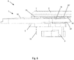
- FIG. 5 is the portion of the container treatment device 4 from FIG. 5 schematically shown again in a perspective side view from above. It can be clearly seen that only the part of the clamp arms 10, which seen from the pivot axes 12 in Direction of the holding portions 11 extends, protrude beyond the staple carrier 4 to the outside.
- the control sections 13 and the biasing element 14 as well as the control cam 3 together with the lever element 30 are arranged under the staple carrier 4.
- a protection of the control sections 13 and the biasing member 14 and the control cam 3 together with the lever member 30 is achieved against contamination, on the other hand protrude no receiving and holding the container disturbing parts in the area below the holding areas eleventh
- FIG. 6 schematically shows a side view of the portion of the container treatment device 6 from FIG. 4 , It can be seen that the bracket arms 10 are supported with their support elements 15 about the pivot axes 12 on the underside 40 of the staple carrier 4 and on a cover side 50 of the counter-plate 5. Further, the bracket arms 10 are supported by means of the spaced from the pivot axes 12 support member 15 'in a rear portion of the active clamping device 6 also on the bottom 40 and the top 50 side. As a result, in the formed of pins and holes 120 storage of the bracket arms 10 game is reduced. In particular, by the support by means of the support elements 15 'so a tilting of the bracket arms 10 with respect to the pivot axes 12 can be prevented.
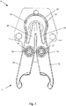
- FIG. 7 schematically shows a plan view of a container treatment device 6 with an active stapling device 1 according to another embodiment, which is essentially that of FIG. 1 equivalent.
- the spaced from the pivot axes 12 supporting elements 15 ' are provided on the biasing member 14 on both sides of the central longitudinal axis 20. Any interfering interaction, such as a disturbing sliding over a ring insert of the cam, can be avoided.
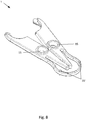
- FIG. 8 schematically shows a perspective side view of the active stapling device 1 from FIG. 7 , Clearly visible are the integrally formed, raised areas, which form the support elements 15 and 15 '.
- FIG. 9 is a schematic side view of the stapler 1 from FIG. 8 shown. Due to the distance 17 between the support elements 15 in the region of the pivot axis 12 and the support elements 15 'spaced therefrom, displacement of a support element 15' parallel to the pivot axis 12 will cause only a marginal tilt corresponding to the tilt angle indicated by reference numeral 18.
- the small play in the direction of the pivot axis 12 between the support elements 15 'and the support areas or support surfaces due to the distance 17 conditions or allows only such a small tilt angle 18 that tilting of the bracket arms 10 can be almost completely avoided in a simple manner. As a result, despite the simple structure of the staple arms 10 and the stapling device 1, a nearly tilt-free storage can be provided.
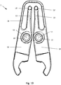
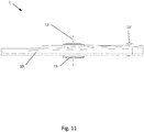
- FIG. 10 and 11 schematically an active clamping device 1 according to a further embodiment can be seen.
- the biasing member 14 has an arcuate shape with straight portions.
- the support members 15, 15 ' are provided as separate parts of a metal.
- the support elements 15 in the region of the pivot axes 12 are presently designed as bearing bushes and inserted into holes or recesses provided for this purpose in the clamp arms 10.
- the outer diameter of the support elements 15 is selected such that the clamping arms 10 are pivotable about the bearing bushes.
- the bushings can be firmly clamped so when installed in a container treatment device 6.
- the support elements are designed as inserts or inserts.
- bracket arms 10 and the biasing member 14 may also be provided as individual parts in the aforementioned embodiments.
Abstract
Die vorliegende Erfindung betrifft aktive Klammervorrichtung (1) zum Halten eines Behälters in einer Behälterbehandlungsvorrichtung, bevorzugt zum Halten eines Getränkebehälters in einem Halsabschnitt, umfassend zwei Klammerarme (10), die jeweils einen Halteabschnitt (11) zum Halten des zu haltenden Behälters und jeweils einen Steuerabschnitt (13) zur Interaktion mit einem Steuernocken (3) zum aktiven Bewegen des jeweiligen Halteabschnitts (11) aufweisen, und ein Vorspannelement (14) zum Vorspannen der Halteabschnitte (11) in eine vorgegebene Position, wobei die Klammerarme (10) und das Vorspannelement (14) einstückig ausgebildet sind, sowie einen Klammerarm und eine Behälterbehandlungsvorrichtung.

Description
Die vorliegende Erfindung betrifft eine aktive Klammervorrichtung zum Halten eines Behälters in einer Behälterbehandlungsvorrichtung und eine Behälterbehandlungsvorrichtung.The present invention relates to an active stapler for holding a container in a container treating apparatus and a container treating apparatus.
Es ist bekannt, in Getränkeabfüllanlagen die jeweils zu befüllenden Behälter beziehungsweise bereits befüllte Behälter mittels Klammervorrichtungen durch die einzelnen Behandlungsstationen der Behälterbehandlungsvorrichtung zu transportieren. Dabei sind unterschiedliche Klammervorrichtungen bekannt, welche die jeweiligen zu behandelnden Behälter auf unterschiedliche Art und Weise halten.It is known to transport in beverage filling the respective containers to be filled or already filled containers by means of stapling devices through the individual treatment stations of the container treatment device. In this case, different stapling devices are known which hold the respective containers to be treated in different ways.
So sind beispielsweise passive Klammervorrichtungen bekannt, welche lediglich durch das Einschieben des jeweiligen Behälters in die Klammervorrichtung elastisch vorgespannt werden und dann den Behälter halten. Aus der
Weiterhin bekannt sind aktive Klammervorrichtungen, bei welchen ein Öffnen und Schließen der jeweiligen Halteabschnitte der Klammervorrichtung mittels eines Aktuators aktiv durchgeführt wird. Solche aktiven Klammervorrichtungen dienen insbesondere dazu, eine sichere und schonende Übernahme der jeweiligen Behälter von einer vorhergehenden Klammervorrichtung zu ermöglichen oder eine ebenso sichere und behälterschonende Übergabe der Behälter an eine nachfolgende Klammervorrichtung zu gewährleisten. Insbesondere kann durch das aktive Öffnen und Schließen der jeweiligen Klammervorrichtung eine erhöhte Reibung an dem jeweiligen Behälter, welche beispielsweise zu einem Verkratzen des Behälters führen könnte, vermieden werden und andererseits kann eine vorgegebene Haltekraft beziehungsweise Klemmkraft eingestellt werden, welche innerhalb eines vorgegebenen Toleranzbereichs der Behälterdimension eingehalten werden kann. Solche aktiven Klammervorrichtungen setzen sich aus einer Vielzahl von Einzelteilen, beispielsweise Klammerarmen, Buchsen, Federelementen, Vorspannelementen und entsprechenden Verbindungselementen zum sicheren Verbinden der vorgenannten Teile, zusammen. Derart aufgebaute Klammervorrichtungen sind mithin aufwendig zu reinigen und weisen einen entsprechend hohen Fertigungsaufwand auf.Also known are active clip devices in which opening and closing of the respective holding sections of the clip device is actively performed by means of an actuator. Such active stapling devices serve, in particular, to enable a secure and gentle transfer of the respective containers from a preceding stapling device or an equally secure and container-friendly transfer of the containers to a subsequent stapling device To ensure stapling device. In particular, can be avoided by the active opening and closing of the respective clamping device increased friction on the respective container, which could for example lead to scratching of the container, and on the other hand, a predetermined holding force or clamping force can be adjusted, which complies with a predetermined tolerance range of the container dimension can be. Such active clamping devices are composed of a plurality of individual parts, for example clip arms, bushings, spring elements, biasing elements and corresponding connecting elements for securely connecting the aforementioned parts together. Thus constructed stapling devices are therefore expensive to clean and have a correspondingly high production cost.
Aus der
Aus der
Die
Ausgehend von dem bekannten Stand der Technik ist es eine Aufgabe der vorliegenden Erfindung, eine verbesserte Klammervorrichtung zum Halten eines Behälters in einer Behälterbehandlungsvorrichtung bereitzustellen.Starting from the known state of the art, it is an object of the present invention to provide an improved clip device for holding a container in a container treatment device.
Die Aufgabe wird durch eine aktive Klammervorrichtung zum Halten eines Behälters in einer Behälterbehandlungsvorrichtung, bevorzugt zum Halten eines Getränkebehälters an einem Halsabschnitt mit den Merkmalen des Anspruchs 1 gelöst. Vorteilhafte Weiterbildungen ergeben sich aus den Unteransprüchen, der Beschreibung und den beigefügten Figuren.The object is achieved by an active clamping device for holding a container in a container treatment device, preferably for holding a beverage container at a neck portion having the features of
Entsprechend wird eine aktive Klammervorrichtung zum Halten eines Behälters in einer Behälterbehandlungsvorrichtung, bevorzugt zum Halten eines Getränkebehälters in einem Halsabschnitt, vorgeschlagen, wobei die aktive Klammervorrichtung zwei Klammerarme, die jeweils einen Halteabschnitt zum Halten des zu haltenden Behälters und jeweils einen Steuerabschnitt zur Interaktion mit einem Steuernocken zum aktiven Bewegen des jeweiligen Halteabschnitts aufweisen, und ein Vorspannelement zum Vorspannen der Halteabschnitte in eine vorgegebene Position umfasst. Erfindungsgemäß sind die Klammerarme und das Vorspannelement einstückig ausgebildet.Accordingly, there is proposed an active stapling apparatus for holding a container in a container treating apparatus, preferably for holding a beverage container in a neck portion, the active stapling apparatus comprising two staple arms each having a holding portion for holding the container to be held and a control portion for interacting with a control cam for actively moving the respective holding section, and comprising a biasing element for biasing the holding sections into a predetermined position. According to the invention, the clamp arms and the biasing element are integrally formed.
Damit sind die Klammerarme über das Vorspannelement miteinander verbunden und die Klammerarme und das Vorspannelement einstückig ausgebildet.Thus, the clamp arms are connected to each other via the biasing member and the clamp arms and the biasing member formed integrally.
Dadurch, dass die Klammerarme über das Vorspannelement miteinander verbunden sind und die Klammerarme und das Vorspannelement einstückig ausgebildet sind, kann eine aktive Klammervorrichtung mit einem besonders einfachen Aufbau bereitgestellt werden.Characterized in that the clamping arms are connected to each other via the biasing member and the clamping arms and the biasing member are integrally formed, an active clamping device can be provided with a particularly simple structure.
Aufgrund der einstückigen Ausbildung ist die Teileanzahl im Vergleich zu herkömmlichen aktiven Klammervorrichtungen signifikant reduziert. Anstatt wie bisher eine Vielzahl an Einzelteilen, beispielsweise einzelne Klammerarme, separater Vorspannelemente mitsamt der zum Verbinden der vorgenannten Teile benötigten Verbindungselemente, vorsehen zu müssen, was einen aufwendigen Zusammenbau sowie aufgrund der vielen Spalte und Ritzen zwischen den einzelnen Teilen einen hohen Reinigungsaufwand bedingt, wird ein einziges Teil bereitgestellt.Due to the one-piece design, the number of parts is significantly reduced compared to conventional active clip devices. Instead, as before, a variety of items, such as individual bracket arms, separate biasing elements together with the need for connecting the aforementioned parts fasteners to provide, which requires a complex assembly and due to the many gaps and cracks between the parts a high cleaning effort, is a single part provided.
Mithin entfällt auch der Aufwand eines Zusammenbaus, zudem sind einstückig aufgebaute Teile besonders einfach zu reinigen, so dass sich die vorgeschlagene aktive Klammervorrichtung insbesondere auch für Einsatz in Anlagen mit hohen Hygieneanforderungen eignet. Zudem kann eine aktive Klammervorrichtung mit den Merkmalen gemäß Anspruch 1 besonders einfach an eine Behälterbehandlungsvorrichtung montiert werden, da nicht auf eine korrekte Ausrichtung einer Vielzahl von einzelnen Teilen zueinander geachtet werden muss.Consequently, eliminates the hassle of assembly, also integrally constructed parts are particularly easy to clean, so that the proposed active stapling device is particularly suitable for use in plants with high hygiene requirements. In addition, an active clamping device with the features according to
Gemäß einer bevorzugten weiteren Ausführungsform spannt das Vorspannelement die Klammerarme in einer Öffnungsposition der Halteabschnitte vor, wobei die Steuerabschnitte zur Interaktion mit dem Steuernocken zum aktiven Bewegen der Halteabschnitte in eine Schließposition ausgebildet sind.According to a preferred further embodiment, the biasing member biases the staple arms in an opening position of the holding portions, the control portions being adapted to interact with the control cam to actively move the holding portions to a closed position.
Dadurch ist erreicht, dass die Klammerarme stets in der Öffnungsposition gehalten sind und nur dann, wenn die Steuerabschnitte aktiv mittels des Steuernockens bewegt werden, beispielsweise durch ein Verschieben der Steuerabschnitte aus ihrer Ausgangslage heraus, welches durch ein Schwenken des Steuernockens erzeugt wird, die Klammerarme entsprechend umschwenken und in die Schließposition der Halteabschnitte wechseln. Schwenkt der Steuernocken zurück, so werden die Klammerarme aufgrund der Spannung in dem Vorspannelement wieder in die Öffnungsposition zurückbewegt und in dieser gehalten. Die Klammervorrichtung weist mithin stets eine geöffnete Position auf und schließt nur dann, wenn die Steuerabschnitte aktiv angesteuert werden, so dass die Klammervorrichtung auch nur dann greift, wenn sie aktiv dazu angesteuert wird. Ferner kann durch das Verschieben der Klammerarme durch den Steuernocken ein besonders sicheres Halten der Behälter erreicht werden.As a result, it is achieved that the clamping arms are always held in the open position and only when the control sections are actively moved by the control cam, for example by shifting the control sections out of their starting position, which is generated by pivoting the control cam, the clamping arms accordingly swing over and change to the closed position of the holding sections. If the control cam pivots back, the clamping arms are moved back into the opening position and held in the opening position due to the tension in the biasing element. Consequently, the clamping device always has an open position and only closes when the control sections are actively activated so that the clamping device only engages when it is actively activated for this purpose. Furthermore, by the displacement of the staple arms by the control cam a particularly secure holding the container can be achieved.
Gemäß einer weiteren bevorzugten Ausführungsform spannt das Vorspannelement die Klammerarme in einer Schließposition der Halteabschnitte vor, wobei die Steuerabschnitte zur Interaktion mit dem Steuernocken zum aktiven Bewegen der Halteabschnitte in eine Öffnungsposition ausgebildet sind.According to another preferred embodiment, the biasing member biases the staple arms in a closed position of the holding portions, the control portions being configured to interact with the control cam to actively move the holding portions to an open position.
Dadurch ist erreicht, dass die Klammerarme stets in die Schließposition vorgespannt sind und nur dann, wenn die Steuerabschnitte aktiv mittels des Steuernockens bewegt werden, beispielsweise durch ein Verschieben der Steuerabschnitte aus ihrer Ausgangslage heraus, welches durch ein Schwenken des Steuernockens erzeugt wird, die Klammerarme entsprechend umschwenken und in die Öffnungsposition der Halteabschnitte wechseln. Schwenkt der Steuernocken zurück, so werden die Klammerarme aufgrund der Vorspannung in dem Vorspannelement wieder in die Schließposition zurückbewegt und in dieser gehalten.This ensures that the clamping arms are always biased into the closed position and only when the control sections are actively moved by the control cam, for example, by moving the control sections out of their initial position, which is generated by a pivoting of the control cam, the clamping arms accordingly swing over and change to the opening position of the holding sections. If the control cam pivots back, the clamping arms are moved back into the closed position due to the bias in the biasing member and held in this.
Die Klammervorrichtung weist mithin stets eine geschlossene Position auf und öffnet nur dann, wenn die Steuerabschnitte aktiv angesteuert werden, so dass die Klammervorrichtung zum Greifen des Behälters vorgespannt ist. Da bei Behälterbehandlungsanlagen zumeist in einem Großteil des Bewegungsbereichs der an daran montierten Klammervorrichtungen zu behandelnde Behälter gehalten werden, kann so auf zusätzliche Elemente verzichtet werden, welche anderweitig zum Halten der Klammervorrichtungen in der geschlossenen Position notwendig wären. Entsprechend können Steuernocken, welche zum aktiven Öffnen der Klammervorrichtungen vonnöten sind, nur in den Bereichen vorgesehen werden, in welchen die Halteabschnitte in der Öffnungsposition vorliegen müssen, beispielsweise zur Übernahme oder Übergabe eines Behälters.Consequently, the clamping device always has a closed position and only opens when the control sections are actively activated, so that the clamping device is biased to grip the container. Since in container treatment plants usually in a large part of the range of movement of the clamp devices mounted on it to be treated containers are kept, can be dispensed with additional elements that otherwise to Holding the staplers in the closed position would be necessary. Correspondingly, control cams, which are required for actively opening the clamping devices, can only be provided in the regions in which the holding sections must be in the open position, for example for taking over or transferring a container.
Um einen besonders vorteilhaften Aufbau der Klammervorrichtung bereitzustellen, können die Klammerarme jeweils um eine Schwenkachse herum schwenkbar sein. Aufgrund des Schwenkens um die vorgegebenen Schwenkachsen können die Öffnungsposition und die Schließposition besonders genau eingenommen werden.In order to provide a particularly advantageous construction of the stapling device, the staple arms can each be pivotable about a pivot axis. Due to the pivoting about the predetermined pivot axes, the opening position and the closing position can be taken particularly accurate.
Wenn die Steuerabschnitte entsprechend einer weiteren bevorzugten Ausführungsform an dem Klammerarmen jeweils in Form eines Hebelarms ausgebildeten sind, kann das Interagieren mit dem Steuernocken auf besonders einfache Weise erfolgen.If, according to a further preferred embodiment, the control sections are formed on the bracket arms in the form of a lever arm in each case, the interaction with the control cam can take place in a particularly simple manner.
Durch ein Bewegen der Hebelarme erfolgt ein Schwenken der Klammerarme um die Schwenkachsen, so dass die Steuernocke relativ zu den Klammerarmen einen fest positionierten Drehpunkt aufweisen kann und lediglich zu verdrehen ist.By moving the lever arms, the clamping arms are pivoted about the pivot axes, so that the control cam relative to the clamp arms can have a fixedly positioned pivot point and is only to be rotated.
Gemäß einer weiteren bevorzugten Ausführungsform ist das Vorspannelement als Bügelfeder ausgebildet, wobei das Vorspannelement bevorzugt in Form eines sich von einem Klammerarm zum anderen Klammerarm erstreckenden Bogens ausgebildet ist.According to a further preferred embodiment, the biasing element is designed as a bow spring, wherein the biasing element is preferably in the form of an extending from one clamp arm to the other bracket arm arc.
Ein derart ausgebildetes Vorspannelement weist eine leicht zu reinigende Form auf, welche zudem in einfacher Weise hergestellt werden kann. Zudem kann über eine Länge der Bügelfeder beziehungsweise des Bogens sowie deren beziehungsweise dessen Profil eine Vorspannkraft, mit welcher das Vorspannelement die Klammerarme vorspannt, besonders genau vorgegeben und/oder an den jeweiligen Anwendungsfall angepasst sein.Such a trained biasing element has an easy-to-clean shape, which can also be produced in a simple manner. In addition, a biasing force with which the biasing element biases the clamping arms, particularly precisely predetermined and / or adapted to the particular application over a length of the bow spring or the bow and its profile.
Wenn die Steuerabschnitte und das Vorspannelement entsprechend einer weiteren bevorzugten Ausführungsform auf einer den Halteabschnitten gegenüberliegenden Seite der Klammerarme angeordnet sind, kann erreicht werden, dass im Bereich des Haltebereichs keine das Halten des Behälters störenden Teile vorliegen. Zudem ist dadurch die Wahrscheinlichkeit, dass die Steuerabschnitte und das Vorspannelement einem Behandlungsmedium, beispielsweise einem in den Behälter zu füllendes oder gefülltes Füllprodukt auf die Steuerabschnitte und das Vorspannelement gelangen, reduziert.If the control sections and the biasing element are arranged according to a further preferred embodiment on a side opposite the holding portions of the clamp arms, it can be achieved that there are no disturbing the holding of the container parts in the region of the holding region. In addition, this reduces the likelihood that the control sections and the biasing element will reach a treatment medium, for example a filling product to be filled or filled into the container, onto the control sections and the biasing element.
Bevorzugt sind bezogen auf die Schwenkachsen die Halteabschnitte jeweils auf einer Seite der Klammerarme angeordnet und die Steuerabschnitte und/oder das Vorspannelement auf der jeweils anderen Seite angeordnet.Preferably, based on the pivot axes, the holding sections are each arranged on one side of the clamp arms and arranged the control sections and / or the biasing member on the other side.
Um die aktive Klammervorrichtung zum Einsatz bei Anwendungen mit erhöhter oder hohen Hygieneanwendungen, beispielsweise aseptische Anwendungen, als besonders geeignet auszubilden, können zumindest die Klammerarme an ihrer Oberseite schräge Flächen zum Ableiten von Flüssigkeiten aufweisen.In order to make the active stapling device particularly suitable for use in applications with elevated or high hygiene applications, for example aseptic applications, at least the staple arms can have oblique surfaces for discharging liquids at their upper side.
Dadurch ist erreicht, dass auf die schrägen Flächen auftreffende Partikel und/oder Flüssigkeiten von der schrägen Fläche schwerkraftbedingt abgleiten und das Ausbilden dauerhafter Verschmutzungen wie etwa ein mikrobiologischer Film vermindert oder gar gänzlich verhindert ist.As a result, it is achieved that particles and / or liquids impinging on the inclined surfaces slide off the oblique surface due to gravity and the formation of permanent contaminants such as a microbiological film is reduced or even completely prevented.
Bevorzugt sind die schrägen Flächen dabei derart ausgebildet, dass sie mit einer senkrecht zu den Schwenkachsen orientierten Ebene einen Winkel von mindestens 3° einschließen und/oder bezogen auf eine Einbauposition der Klammervorrichtung an einer Behälterbehandlungsvorrichtung mit einer senkrecht zur Richtung der Erdbeschleunigung orientierten Ebene einen Winkel von mindestens 3° einschließen.In this case, the oblique surfaces are preferably designed such that they enclose an angle of at least 3 ° with a plane oriented perpendicular to the pivot axes and / or with respect to an installation position of the stapling device on a container treatment device with a plane oriented perpendicular to the direction of gravitational acceleration at least 3 °.
Ferner sind die schrägen Flächen bevorzugt derart orientiert, dass ein Abgleiten von Partikeln nach außen, mithin von einer Mitte oder Mittelebene der Klammervorrichtung weg bereitgestellt ist. Mit anderen Worten sind zumindest die Klammerarme jeweils nach außen hin abgeschrägt.Furthermore, the inclined surfaces are preferably oriented in such a way that a sliding of particles is provided to the outside, thus away from a center or center plane of the stapler. In other words, at least the clip arms are each bevelled outwardly.
Gemäß einer weiteren bevorzugten Ausführungsform weisen die Klammerarme jeweils voneinander beabstandete Stützelemente zum Stützen der Position der Klammerarme in Bezug auf eine Einbauposition der Klammervorrichtung, bevorzugt in Bezug auf die Schwenkachsen, gegen ein Verkippen auf, wobei bevorzugt jeweils ein Stützelement im Bereich der jeweiligen Schwenkachse beziehungsweise um diese herum und/oder ein Stützelement beabstandet von der jeweiligen Schwenkachse, bevorzugt an einem Ende des Steuerbereichs, besonders bevorzugt an einem freien Ende des als Haltearm ausgebildeten Steuerbereichs, und/oder an dem Vorspannelement, ausgebildet ist.According to a further preferred embodiment, the clamping arms each have mutually spaced support members for supporting the position of the clamping arms with respect to an installation position of the clamping device, preferably with respect to the pivot axes, against tilting, wherein preferably in each case a support element in the region of the respective pivot axis or to this around and / or a support element spaced from the respective pivot axis, preferably at one end of the control region, particularly preferably at a free end of the control arm formed as a support portion, and / or on the biasing member, is formed.
Die Stützelemente wirken bevorzugt mit entsprechenden Abstützbereichen beziehungsweise Abstützflächen der Behälterbehandlungsvorrichtung zusammen, an welchen sie sich abstützen und so die Klammervorrichtung bezogen auf die Schwenkachsen gegen ein Verkippen stützen. Ein sich in einer Lagerung der Klammervorrichtung an den Schwenkachsen ausbildenden Lagerspiel kann hierdurch nahezu oder gar gänzlich verhindert werden.The support elements preferably cooperate with corresponding support areas or support surfaces of the container treatment device, on which they are supported and thus support the clamping device with respect to the pivot axes against tilting. One yourself In a storage of the stapler on the pivot axes forming bearing clearance can thereby be almost or even completely prevented.
Gemäß einer weiteren bevorzugten Ausführungsform sind die Steuerabschnitte elastisch ausgebildet, wobei bevorzugt jeweils an einem den Steuerabschnitt ausbildenden Hebelarm ein elastisches Element, bevorzugt einstückig, ausgebildet ist und/oder die Steuerabschnitte formelastisch ausgebildet sind, wobei bevorzugt der Hebelarm eine Länge und ein Profil aufweist, derart dass der Hebelarm bevorzugt zumindest innerhalb eines Vorgabebereichs elastisch verformbar ist.According to a further preferred embodiment, the control sections are elastically formed, wherein an elastic element, preferably in one piece, is preferably formed on a control arm forming the control section, and / or the control sections are formed elastically, wherein preferably the lever arm has a length and a profile, in such a way that the lever arm is preferably elastically deformable at least within a default range.
Dadurch kann der Steuerabschnitt entsprechend der von dem Steuernocken aufgebrachten Kraft folgen, und mittels der Vorspannung entsprechend ein sanftes Aufbringen dieser Kraft über die Klammerarme auf den Halteabschnitt ein sanftes und gleichzeitig zuverlässiges Halten des Behälters ermöglichen. Ferner kann zum einen ein sanftes Betätigen der Klammervorrichtung mittels der Steuernocke erreicht werden, und zum anderen können über das dadurch erreichte elastische Verformungsvermögen der Steuerabschnitte Toleranzen in der Behältergröße ausgeglichen werden, so dass entsprechend ein Halten von Behältern innerhalb eines bestimmten Toleranzbereiches sicher möglich ist. Dies ermöglicht auch in bestimmten Grenzen das sichere Halten von falsch gegriffenen Behältern.Thereby, the control portion can follow the force applied by the control cam, and by means of the biasing force correspondingly a gentle application of this force to the holding portion via the clamping arms, enables a smooth yet reliable holding of the container. Furthermore, on the one hand, a gentle actuation of the clamping device can be achieved by means of the control cam, and on the other hand tolerances can be compensated in the container size over the elastic deformation capacity of the control sections achieved thereby, so that holding containers within a certain tolerance range is certainly possible. This also allows within certain limits the secure holding of incorrectly grasped containers.
Wenn die Klammerarme bevorzugt samt Halteabschnitten und Steuerabschnitten und das Vorspannelement einteilig als 3D-Druck-Teil oder Spritzgussteil, ausgebildet sind, kann eine einfache und kostengünstige Herstellung und gleichzeitig eine hohe Formfreiheit erreicht werden. Mithin kann die Form der Klammerarme und des Vorspannelement einstückig ausgebildet sein und dennoch gezielt an die Erfordernisse des jeweiligen Anwendungsfalls angepasst werden.If the clamping arms preferably together with holding sections and control sections and the biasing element integrally formed as a 3D printing part or injection molded part, a simple and cost-effective production and at the same time a high freedom of form can be achieved. Thus, the shape of the staple arms and the biasing element may be integrally formed and yet be adapted specifically to the requirements of the particular application.
Gemäß einer weiteren bevorzugten Ausführungsform sind die Klammerarme bevorzugt samt Halteabschnitten und Steuerabschnitten und das Vorspannelement einteilig aus einem Kunststoff, besonders bevorzugt aus einem technischen Kunststoff oder einem Hochleistungskunststoff, ganz besonders bevorzugt aus PEEK, ausgebildet.According to a further preferred embodiment, the clamping arms are preferably formed together with holding sections and control sections and the biasing element in one piece from a plastic, particularly preferably from a technical plastic or a high-performance plastic, most preferably made of PEEK.
Aufgrund der guten Verarbeitbarkeit von Kunststoffen ist eine einfache Fertigung erreicht. Zudem kann die aktive Klammervorrichtung einerseits die benötigten mechanischen Eigenschaften aufweisen, beispielsweise kann durch die Wahl des Kunststoffs, bevorzugt PA, insbesondere PA6 oder PA66, oder PEEK, eine hohe Dauerbeständigkeit gegen mechanisches Versagen und eine genügende Vorspannung bereitgestellt werden.Due to the good processability of plastics, a simple production is achieved. In addition, the active clamping device on the one hand have the required mechanical properties, for example, can be provided by the choice of plastic, preferably PA, in particular PA6 or PA66, or PEEK, a high durability against mechanical failure and sufficient bias.
Zudem ist es möglich, auf bei herkömmlichen aktiven Klammervorrichtungen notwendige Lagerbuchsen, mittels welchen in der Regel metallene Klammerarme gelagert sind, verzichtet werden, da in die Klammerarme selbst aufgrund der Eigenschaften, insbesondere der Gleiteigenschaften des ausgewählten Kunststoffs, insbesondere bei PEEK, eine Lagerbohrung mit den erforderlichen Toleranzen und Gleiteigenschaften in einfacher Weise einbringbar ist.In addition, it is possible to be necessary in conventional active clamping devices bearing bushes, by means of which usually metal clamp arms are stored, are omitted because in the bracket arms itself due to the properties, in particular the sliding properties of the selected plastic, especially in PEEK, a bearing bore with the required tolerances and sliding properties can be introduced in a simple manner.
Mithin kann durch die einstückige Ausbildung von Klammerarmen und Vorspannelement aus dem Kunststoff ein einfach zu fertigendes und leicht zu montierendes und demontierendes Austauschteil bereitgestellt werden. Verschlissene oder alte Teile können granuliert und das daraus gewonnen Material wieder für die Herstellung neuer Teile verwendet werden, so dass sich der Materialeinsatz verringert. Zudem weist eine derart ausgebildete aktive Klammervorrichtung aufgrund des Kunststoffs der Klammerarme und des Vorspannelements, insbesondere in Vergleich zu herkömmlichen Klammervorrichtungen mit Klammerarmen und/oder Vorspannelementen aus Metall, ein geringes Gewicht auf.Thus, by the one-piece design of clip arms and biasing element from the plastic an easy to be manufactured and easy to install and dismantle replacement part can be provided. Worn or old parts can be granulated and the resulting material used again for the production of new parts, so that the use of materials is reduced. In addition, due to the plastic of the clamping arms and the biasing element, in particular in comparison to conventional clamping devices with clamp arms and / or biasing elements made of metal, an active clamping device formed in this way has a low weight.
Die oben gestellte Aufgabe wird ferner durch einen Klammerarm zum Halten eines Behälters in einer Klammervorrichtung mit den Merkmalen des Anspruchs 12 gelöst. Vorteilhafte Weiterbildungen ergeben sich aus den Unteransprüchen, der Beschreibung und den beigefügten Figuren.The above object is further achieved by a stapling arm for holding a container in a stapling device having the features of
Entsprechend wird ein Klammerarm zum Halten eines Behälters in einer Klammervorrichtung vorgeschlagen, umfassend einen Halteabschnitt zum Halten des zu haltenden Behälters und einen Steuerabschnitt zur Interaktion mit einem Steuernocken zum aktiven Bewegen des Halteabschnitts. Erfindungsgemäß weist der Klammerarm mindestens zwei voneinander beabstandete Stützelemente zum Stützen der Position des Klammerarms in Bezug auf eine Schwenkachse des Klammerarms gegen ein Verkippen in Bezug auf eine Einbauposition in der Klammervorrichtung auf.Accordingly, there is proposed a stapling arm for holding a container in a stapling device, comprising a holding portion for holding the container to be held and a control portion for interacting with a cam for actively moving the holding portion. According to the invention, the stapling arm has at least two spaced supporting members for supporting the position of the stapling arm with respect to a pivoting axis of the stapling arm against tilting with respect to an installation position in the stapling device.
Die Stützelemente wirken bevorzugt mit entsprechenden Abstützbereichen beziehungsweise Abstützflächen einer Behälterbehandlungsvorrichtung zusammen, an welchen sie sich abstützen und so den Klammerarm beziehungsweise eine den Klammerarm aufweisende Klammervorrichtung bezogen auf die Schwenkachsen gegen ein Verkippen stützen. Ein sich in einer Lagerung des Klammerarms an der Schwenkachse ausbildendes Lagerspiel kann hierdurch nahezu oder gar gänzlich verhindert werden.The support elements preferably cooperate with corresponding support areas or support surfaces of a container treatment device, on which they are supported and thus support the staple arm or a stapling arm having stapling device with respect to the pivot axes against tilting. A bearing clearance forming in a bearing of the clamp arm on the pivot axis can thereby be almost or even completely prevented.
Dadurch, dass der Klammerarm mindestens zwei voneinander beabstandete Stützelemente zum Stützen der Position des Klammerarms in Bezug auf eine Schwenkachse des Klammerarms gegen ein Verkippen in Bezug auf eine Einbauposition in der Klammervorrichtung aufweist, kann eine aktive Klammervorrichtung mit einem besonders einfachen Aufbau bereitgestellt werden.By having the clamp arm at least two spaced support members for supporting the position of the clamp arm with respect to a pivot axis of the clamp arm against tilting with respect to an installation position in the clamp apparatus, an active clamp apparatus having a particularly simple structure can be provided.
Da der Klammerarm selbst die mindestens zwei voneinander beabstandeten Stützelemente aufweist, kann die Teileanzahl im Vergleich zu herkömmlichen Klammervorrichtungen reduziert werden. Auf bisher erforderliche gesonderte Einheiten oder Vorrichtungen zum Abstützen der Klammerarme in der Klammervorrichtung und/oder zum Abstützten des in der Klammervorrichtung gehaltenen Behälters kann mithin verzichtet werden, wodurch ein Zusammenbau einer die Klammerarme aufweisenden Klammervorrichtung und/oder Behälterbehandlungsvorrichtung weniger aufwendig ist und aufgrund einer Reduzierung von Spalten und Ritzen zwischen den einzelnen Teilen der Reinigungsaufwand einer solchen Klammervorrichtung und/oder Behälterbehandlungsvorrichtung reduziert ist.Since the clamp arm itself has the at least two spaced-apart support elements, the number of parts can be reduced in comparison to conventional clamping devices. Thus far required separate units or devices for supporting the staple arms in the stapler and / or for supporting the container held in the stapler can be dispensed with, whereby assembly of the staple arms having stapler and / or container treatment device is less expensive and due to a reduction of Columns and cracks between the individual parts of the cleaning effort of such a clamping device and / or container treatment device is reduced.
Zudem kann ein Klammerarm mit den Merkmalen gemäß Anspruch 12 besonders einfach an eine Klammervorrichtung und/oder an eine Behälterbehandlungsvorrichtung montiert werden, da nicht auf eine korrekte Ausrichtung zwischen dem Klammerarm und einer separaten Stützvorrichtung zueinander geachtet werden muss.Gemäß einer weiteren bevorzugten Ausführungsform des Klammerarms ist jeweils ein Stützelement im Bereich der Schwenkachse und ein Stützelement beabstandet von der Schwenkachse, bevorzugt an einem Ende des Steuerbereichs, besonders bevorzugt an einem freien Ende eines als Haltearm ausgebildeten Steuerbereichs, ausgebildet. Dadurch ist eine effektive Lagerung des Klammerarms und ein besonders effektiver Schutz gegen ein Verkippen bereitgestellt.In addition, a stapling arm with the features according to claim 12 can be mounted particularly easily on a stapler and / or on a container treatment device, since care must be taken not to a correct alignment between the stapling arm and a separate support device to each other according to another preferred embodiment of the stapler in each case a support element in the region of the pivot axis and a support element spaced from the pivot axis, preferably at one end of the control region, particularly preferably formed at a free end of a control region designed as a support arm. As a result, an effective storage of the stapling arm and a particularly effective protection against tilting is provided.
Mit zunehmendem Abstand zwischen dem Stützelement im Bereich der Schwenkachse und dem davon beabstandeten Stützelement ist ein in der Lagerung des Klammerarms mögliches Spiel zunehmend reduziert. Ein Verschieben des beanstandeten Stützelements in Richtung der Schwenkachse resultiert mit zunehmenden Abstand, mithin mit einer zunehmenden Länge, die zwischen den beiden Stützelementen vorliegt, einen entsprechend kleineren Verkippwinkel.With increasing distance between the support member in the region of the pivot axis and the support member spaced therefrom a possible in the storage of the stapling arm game is increasingly reduced. A displacement of the objected support element in the direction of the pivot axis results with increasing distance, thus with an increasing length, which is present between the two support elements, a correspondingly smaller tilt angle.
Bevorzugt ist der Steuerabschnitt elastisch ausgebildet, wobei bevorzugt an einem den Steuerabschnitt ausbildenden Hebelarm ein elastisches Element ausgebildet ist und/oder der Steuerabschnitt formelastisch ausgebildet ist, wobei bevorzugt der Hebelarm eine Länge und ein Profil aufweist, derart dass der Hebelarm bevorzugt zumindest innerhalb eines Vorgabebereichs elastisch verformbar ist. Dadurch kann der Steuerabschnitt entsprechend der von dem Steuernocken aufgebrachten Kraft folgen, und mittels der Vorspannung entsprechend ein sanftes Aufbringen dieser Kraft auf den Halteabschnitt ein sanftes und gleichzeitig zuverlässiges Halten des Behälters ermöglichen. Ferner kann zum einen ein sanftes Betätigen der Klammervorrichtung mittels der Steuernocke erreicht werden, und zum anderen können über das dadurch erreichte elastische Verformungsvermögen der Steuerabschnitte Toleranzen in der Behältergröße ausgeglichen werden, so dass entsprechend ein Halten von Behältern innerhalb eines bestimmten Toleranzbereiches sicher möglich ist. Dies ermöglicht auch in bestimmten Grenzen das sichere Halten von falsch gegriffenen Behältern.Preferably, the control portion is formed elastically, wherein preferably an elastic element is formed on a control portion forming the lever arm and / or the control portion is formed elastically, wherein preferably the lever arm has a length and a profile, such that the lever arm preferably at least within a default range is elastically deformable. Thereby, the control portion can follow the force applied by the control cam, and by means of the biasing force correspondingly a gentle application of this force to the holding portion, enables a smooth and reliable holding of the container. Furthermore, on the one hand, a gentle actuation of the clamping device can be achieved by means of the control cam, and on the other hand tolerances can be compensated in the container size over the elastic deformation capacity of the control sections achieved thereby, so that holding containers within a certain tolerance range is certainly possible. This also allows within certain limits the secure holding of incorrectly grasped containers.
Wenn der Klammerarm und zumindest ein Stützelement einteilig ausgebildet sind, kann eine einfache und kostengünstige Herstellung und gleichzeitig eine hohe Formfreiheit erreicht werden.If the clamp arm and at least one support element are integrally formed, a simple and cost-effective production and at the same time a high freedom of form can be achieved.
Gemäß einer weiteren bevorzugten Ausführungsform sind der Klammerarm und zumindest ein Stützelement als 3D-Druck-Teil oder Spritzgussteil ausgebildet, bevorzugt aus einem Kunststoff, besonders bevorzugt aus einem technischen Kunststoff oder einem Hochleistungskunststoff, ganz besonders bevorzugt aus PEEK.According to a further preferred embodiment, the clamp arm and at least one support element are designed as 3D printing part or injection molded part, preferably made of a plastic, more preferably of a technical plastic or a high performance plastic, most preferably of PEEK.
Aufgrund der guten Verarbeitbarkeit von Kunststoffen ist eine einfache Fertigung erreicht. Zudem kann der Klammerarm einerseits die benötigten mechanischen Eigenschaften aufweisen, beispielsweise kann durch die Wahl des Kunststoffs, bevorzugt PA, insbesondere PA6 oder PA66, oder PEEK, eine hohe Dauerbeständigkeit gegen mechanisches Versagen und eine genügende Vorspannung bereitgestellt werden.Due to the good processability of plastics, a simple production is achieved. In addition, on the one hand, the stapling arm can have the required mechanical properties; for example, by choosing the plastic, preferably PA, in particular PA6 or PA66, or PEEK, a high durability against mechanical failure and sufficient preload can be provided.
Zudem ist es möglich, auf bei herkömmlichen Klammerarmen notwendige Lagerbuchsen, mittels welchen in der Regel metallene Klammerarme gelagert sind, zu verzichten, da in die Klammerarme selbst aufgrund der Eigenschaften, insbesondere der Gleiteigenschaften des ausgewählten Kunststoffs, insbesondere bei PEEK, eine Lagerbohrung mit den erforderlichen Toleranzen und Gleiteigenschaften in einfacher Weise einbringbar ist.In addition, it is possible to dispense with necessary in conventional clamp arms bearing bushes by means of which usually metal clamp arms are stored, since in the bracket arms itself due to the properties, in particular the sliding properties of the selected plastic, especially in PEEK, a bearing bore with the required Tolerances and sliding properties can be introduced in a simple manner.
Mithin kann durch die Ausbildung des Klammerarms und/oder des zumindest einen Stützelements aus dem Kunststoff ein einfach zu fertigendes und leicht zu montierendes und demontierendes Austauschteil bereitgestellt werden. Verschlissene oder alte Teile können granuliert und das daraus gewonnen Material wieder für die Herstellung neuer Teile verwendet werden, so dass sich der Materialeinsatz verringert. Zudem weist ein derart ausgebildeter Klammerarm und/oder ein derart ausgebildetes Stützelement aufgrund des Kunststoffs, insbesondere in Vergleich zu herkömmlichen Klammervorrichtungen mit Klammerarmen aus Metall und separaten Stützvorrichtungen, ein geringes Gewicht auf.Thus, by the formation of the clamp arm and / or the at least one support element made of the plastic, an easy-to-manufacture and easy to assemble and disassemble exchange part can be provided. Worn or old parts can be granulated and the resulting material used again for the production of new parts, so that the use of materials is reduced. In addition, such a trained clamp arm and / or a support element formed in this way due to the plastic, in particular in comparison to conventional Clamping devices with metal clamp arms and separate support devices, light weight.
Alternativ und/oder zusätzlich kann gemäß einer weiteren bevorzugten Ausführungsform zumindest ein Stützelement ein anderes Material als der Klammerarm aufweisen, bevorzugt ein Metall beziehungsweise eine Metalllegierung und/oder kann zumindest ein Stützelement als separates Teil, bevorzugt als Lagerbuchse, bereitgestellt sein. Dadurch ist es möglich, das Stützelement mit den erforderlichen mechanischen Eigenschaften, insbesondere einer erforderlichen Verformungsfestigkeit und Abriebfestigkeit bereitzustellen, und andere, weniger beanspruchte Bereiche des Klammerarms aus einem anderen Material, das beispielsweise leichter und/oder günstiger ist, auszubilden.Alternatively and / or additionally, according to a further preferred embodiment, at least one support element may comprise a material other than the clamp arm, preferably a metal or a metal alloy and / or at least one support element may be provided as a separate part, preferably as a bearing bush. This makes it possible to provide the support element with the required mechanical properties, in particular a required deformation resistance and abrasion resistance, and other, less stressed areas of the staple arm of another material, which is for example lighter and / or cheaper form.
Bevorzugt ist das zumindest eine Stützelement, das ein anderes Material aufweist, als der Klammerarm, in den Klammerarm eingeschoben und/oder als Einsatz eingespritzt beziehungsweise dreidimensional umdruckt.Preferably, this is at least one support element having a different material than the staple arm, inserted into the staple arm and / or injected as an insert or reprinted three-dimensionally.
Um die aktive Klammervorrichtung zum Einsatz bei Anwendungen mit erhöhter oder hohen Hygieneanforderungen, beispielsweise zum Einsatz in aseptischen Anwendungen, als besonders geeignet auszubilden, kann eine Oberseite des Klammerarms zumindest eine schräg verlaufende Fläche zum Ableiten von Flüssigkeiten aufweisen.To make the active stapling device particularly suitable for use in applications with increased or high hygiene requirements, for example for use in aseptic applications, an upper side of the stapling arm may have at least one inclined surface for discharging liquids.
Dadurch ist erreicht, dass auf die schrägen Flächen auftreffende Partikel und/oder Flüssigkeiten von der schrägen Fläche schwerkraftbedingt abgleiten und das Ausbilden dauerhafter Verschmutzungen wie etwa ein mikrobiologischer Film vermindert oder gar gänzlich verhindert ist.As a result, it is achieved that particles and / or liquids impinging on the inclined surfaces slide off the oblique surface due to gravity and the formation of permanent contaminants such as a microbiological film is reduced or even completely prevented.
Bevorzugt sind die schrägen Flächen dabei derart ausgebildet, dass sie mit einer senkrecht zu den Schwenkachsen orientierten Ebene einen Winkel von mindestens 3° einschließen und/oder bezogen auf eine Einbauposition der Klammervorrichtung an einer Behälterbehandlungsvorrichtung mit einer senkrecht zur Richtung der Erdbeschleunigung orientierten Ebene einen Winkel von mindestens 3° einschließen.In this case, the oblique surfaces are preferably designed such that they enclose an angle of at least 3 ° with a plane oriented perpendicular to the pivot axes and / or with respect to an installation position of the stapling device on a container treatment device with a plane oriented perpendicular to the direction of gravitational acceleration at least 3 °.
Ferner sind die schrägen Flächen bevorzugt derart orientiert, dass ein Abgleiten von Partikeln nach außen, mithin von einer Mitte oder Mittelebene einer zumindest einen Klammerarm aufweisenden Klammervorrichtung weg bereitgestellt ist. Mit anderen Worten sind die Klammerarme dann jeweils nach außen hin abgeschrägt.Furthermore, the oblique surfaces are preferably oriented in such a way that a sliding away of particles towards the outside, that is to say away from a center or median plane of a stapling device having at least one stapling arm, is provided. In other words, the bracket arms are then beveled outwardly.
Die oben gestellte Aufgabe wird weiterhin durch eine Behälterbehandlungsvorrichtung zum Behandeln von Behältern gelöst, welche einen Klammerträger und zumindest eine an diesem angeordnete aktive Klammervorrichtung gemäß einer der vorstehenden Ausführungsformen und/oder eine Klammervorrichtung mit zumindest einem Klammerarm gemäß einer der vorstehenden Ausführungsformen aufweist. Vorteilhafte Weiterbildungen der Behälterbehandlungsvorrichtung ergeben sich aus der vorliegenden Beschreibung und den Figuren.The above object is further achieved by a container treatment apparatus for treating containers, which has a staple carrier and at least one arranged thereon active stapling device according to one of the preceding embodiments and / or a stapling device with at least one stapling arm according to one of the preceding embodiments. Advantageous developments of the container treatment device will become apparent from the present description and the figures.
Alternativ können die Klammerarme und das Vorspannelement in den vorgenannten Ausführungsformen auch als Einzelteile bereitgestellt sein.Alternatively, the bracket arms and the biasing member may be provided as individual parts in the aforementioned embodiments.
Bevorzugte weitere Ausführungsformen der Erfindung werden durch die nachfolgende Beschreibung der Figuren näher erläutert. Dabei zeigen:
Figur 1- schematisch eine perspektivische Seitenansicht einer aktiven Klammervorrichtung zum Halten eines Behälters;
Figur 2- schematisch eine Vorderansicht der aktiven Klammervorrichtung aus
Figur 1 ; Figur 3- schematisch eine Draufsicht der aktiven Klammervorrichtung aus
Figur 1 in Interaktion mit einem Steuernocken; Figur 4- schematisch eine perspektivische Seitenansicht von unten eines Teilbereichs einer Behälterbehandlungsvorrichtung mit einer aktiven Klammervorrichtung gemäß
Figur 1 ; Figur 5- schematisch eine perspektivische Seitenansicht von oben des Teilbereichs der Behälterbehandlungsvorrichtung aus
Figur 4 ; Figur 6- schematisch eine Seitenansicht des Teilbereichs der Behälterbehandlungsvorrichtung aus
Figur 4 ; - Figur 7
- schematisch eine Draufsicht einer Behälterbehandlungsvorrichtung mit einer aktiven Klammervorrichtung gemäß einer weiteren Ausführungsform;
- Figur 8
- schematisch eine perspektivische Seitenansicht der aktiven Klammervorrichtung aus
Figur 7 ; - Figur 9
- schematisch eine Seitenansicht der Klammervorrichtung aus
Figur 8 ; Figur 10- schematisch eine aktive Klammervorrichtung gemäß einer weiteren Ausführungsform; und
Figur 11- schematisch die aktive Klammervorrichtung aus
Figur 10 in einer Seitenansicht.
- FIG. 1
- schematically a perspective side view of an active clamping device for holding a container;
- FIG. 2
- schematically a front view of the active stapling device
FIG. 1 ; - FIG. 3
- schematically a plan view of the active stapling device
FIG. 1 in interaction with a control cam; - FIG. 4
- schematically a perspective side view from below of a portion of a container treatment device with an active stapling device according to
FIG. 1 ; - FIG. 5
- schematically a perspective side view from above of the portion of the container treatment device
FIG. 4 ; - FIG. 6
- schematically a side view of the portion of the container treatment device
FIG. 4 ; - FIG. 7
- schematically a top view of a container treatment device with an active stapler according to another embodiment;
- FIG. 8
- schematically a perspective side view of the active stapling device
FIG. 7 ; - FIG. 9
- schematically a side view of the stapler
FIG. 8 ; - FIG. 10
- schematically an active clamping device according to another embodiment; and
- FIG. 11
- schematically the active stapler
FIG. 10 in a side view.
Im Folgenden werden bevorzugte Ausführungsbeispiele anhand der Figuren beschrieben. Dabei werden gleiche, ähnliche oder gleichwirkende Elemente in den unterschiedlichen Figuren mit identischen Bezugszeichen versehen, und auf eine wiederholte Beschreibung dieser Elemente wird teilweise verzichtet, um Redundanzen zu vermeiden.In the following, preferred embodiments will be described with reference to the figures. In this case, identical, similar or equivalent elements in the different figures are provided with identical reference numerals, and a repeated description of these elements is partially omitted in order to avoid redundancies.
In
Die aktive Klammervorrichtung 1 weist zwei Klammerarme 10 mit jeweils einem Halteabschnitt 11 zum Halten des zu haltenden Behälters auf. Der Halteabschnitt 11 greift dabei typischer Weise an einem Halsabschnitt des zu haltenden Behälters an - beispielsweise direkt unter einem Tragring. Die aktive Klammervorrichtung 1 kann entsprechend vorteilhaft für ein "neck handling" von Behältern in einer Behälterbehandlungsvorrichtung vorgesehen seni.The
Die Klammerarme 10 weisen weiterhin jeweils einen Steuerabschnitt 13 zur Interaktion mit einem hier nicht gezeigten Steuernocken zum aktiven Bewegen der Klammerarme 10 und damit auch der Halteabschnitte 11 auf.The
Jeder Klammerarm 10 weist zwischen dem Halteabschnitt 11 und dem Steuerabschnitt 13 eine Bohrung 120 auf, durch die eine Schwenkachse 12 verläuft. Entsprechend kann durch eine schwenkbare Anbringung der Klammerarme 10 an einer Behälterbehandlungsvorrichtung beispielsweise mittels jeweils durch die Bohrungen 120 geführten Bolzen eine Verschwenkung um die Schwenkachse 12 erreicht werden.Each
Die Steuerabschnitte 13 der Klammerarme 10 sind jeweils in Form eines sich von dem Bereich der Schwenkachse 12 nach hinten, mithin bezogen auf die Schwenkachse 12 auf die dem Halteabschnitt 11 gegenüberliegenden Seite, erstreckenden Hebelarms 130 ausgebildet.The
Die Klammerarme 10 sind über ein Vorspannelement 14 in Form eines sich von einem Klammerarm 10 zum anderen Klammerarm 10 erstreckenden Bogens 140 miteinander verbunden. Die Klammerarme 10 und das Vorspannelement 14 sind dabei einstückig miteinander ausgebildet. Der Bogen 140 erstreckt sich von dem Bereich der Schwenkachsen 12 nach hinten und umspannt die Hebelarme 130.The
Das Vorspannelement 14 spannt die Klammerarme 10 in einer Öffnungsposition der Halteabschnitte 11 vor. Mithin sind die Klammerarme 10 durch das Vorspannelement 14 in einer Position zueinander gehalten, in welcher die Halteabschnitte 11 wie in
Um die Bohrungen 120 herum ist jeweils ein ringförmiges Stützelement 15 vorgesehen. An einem freien Ende 132 des jeweiligen Hebelarms 130 ist jeweils ein weiteres Stützelement 15' vorgesehen. Die Stützelemente 15, 15' dienen dazu, die Position der Klammerarme 10 in Bezug auf eine Einbauposition der Klammervorrichtung 1 an der Behälterbehandlungsvorrichtung abzustützen, wie weiter im Detail zu
Ferner weisen die Klammerarme 10 an ihrer Oberseite schräge Flächen 16 zum Ableiten von Flüssigkeiten auf. Dadurch wird erreicht, dass auf die schrägen Flächen 16 auftreffende Partikel und/oder Flüssigkeiten von der schrägen Fläche 16 schwerkraftbedingt abgleiten und das Ausbilden dauerhafter Verschmutzungen wie etwa ein mikrobiologischer Film vermindert oder gar gänzlich verhindert ist. Die schrägen Flächen 16 erstrecken sich zumindest in dem Bereich der aktiven Klammervorrichtung 1, in der diese in den Behandlungsbereich der Behälterbehandlungsvorrichtung hereinragen. Dies ist typischer Weise zumindest im Bereich zwischen dem Halteabschnitt 11 und der Schwenkachse 12 der Fall. Dies ist in den
In einer bevorzugten Weiterbildung erstrecken sich die schrägen Flächen im Wesentlichen über die gesamte Oberseite der Klammerarme 10 und zu großen Teilen auch über das als Bogen 140 ausgebildete Vorspannelement 14.In a preferred embodiment, the oblique surfaces extend substantially over the entire upper side of the
Die schrägen Flächen 16 sind dabei derart orientiert, dass sie in Bezug auf eine Mittellängsebene beziehungsweise Mittelachse 2 gesehen ein Abgleiten von Partikeln nach außen, mithin von der Mittellängsebene beziehungsweise Mittelachse 2 der Klammervorrichtung 1 weg bereitgestellt ist. Mit anderen Worten sind zumindest die Oberseiten der Klammerarme 10 jeweils nach außen hin abgeschrägt. Von der Abschrägung ausgenommen sind die Stützelemente 15, 15' deren Oberflächen sich senkrecht zu den Schwenkachsen 12 erstrecken, um ein stabiles Anliegen an einem hier nicht gezeigten Befestigungsbereich der Behälterbehandlungsvorrichtung zu ermöglichen.The oblique surfaces 16 are oriented in such a way that, viewed in relation to a central longitudinal plane or
In
Zum Öffnen der Klammervorrichtung 1 beziehungsweise, um die Haltebereiche 11 wieder in ihre Öffnungsposition zu bewegen, ist der Steuernocken 3 wieder in die in
Die Klammerarme 10 sind mitsamt ihrer Halteabschnitte 11 und Steuerabschnitte 13 und dem Vorspannelement 14 einteilig aus einem Kunststoff, vorliegend PEEK, ausgebildet. Aufgrund der Elastizität des PEEK und der Form der Hebelarme 130, vorliegend ihrer Länge und ihres Querschnittprofils, sind die Steuerabschnitte 13 formelastisch ausgebildet. Mit anderen Worten sind die Hebelarme 130 basierend auf der Elastizität des PEEK als elastische Biegebalken ausgebildet. Dadurch kann der Steuerabschnitt 13 entsprechend der von dem Steuernocken 3 aufgebrachten Kraft folgen, und mittels der Vorspannung entsprechend ein sanftes Aufbringen dieser Kraft über die Klammerarme 10 auf den Halteabschnitt 11 ein sanftes und gleichzeitig zuverlässiges Halten des Behälters ermöglichen. Ferner kann zum einen ein sanftes Betätigen der Klammervorrichtung 1 mittels des Steuernockens 3 erreicht werden, und zum anderen können über das dadurch erreichte elastische Verformungsvermögen der Steuerabschnitte 13 Toleranzen in der Behältergröße ausgeglichen werden, so dass entsprechend ein Halten von Behältern innerhalb eines bestimmten Toleranzbereiches sicher möglich ist. Dies ermöglicht auch in bestimmten Grenzen das sichere und beschädigungsfreie Halten von falsch gegriffenen oder falsch orientiert zugeführten Behältern.The
Das einstückige Teil, welches die Klammerarme 10 samt Halteabschnitten 11 und Steuerabschnitten 13 und das Vorspannelement 14 umfasst, ist vorliegend mittels eines 3D-DruckVerfahrens hergestellt. Alternativ kann es beispielsweise auch mittels Spritzgießen hergestellt sein.The one-piece part, which comprises the
Aus
Die Behälterbehandlungsvorrichtung 6 weist einen um eine nicht gezeigte Achse drehbaren Klammerträger 4 auf. An dessen Unterseite 40 ist eine Vielzahl von aktiven Klammervorrichtungen 1 gemäß den
Der Steuernocken 3 weist unterhalb der Gegenplatte 5 ein Hebelelement 30 auf, welches durch Interaktion mit einem nicht gezeigten Aktuator der Behälterbehandlungsvorrichtung 6 um 90° gedreht werden kann, so dass der Steuernocken 3 zwischen der in
In
In
Den
Die von den Schwenkachsen 12 beabstandeten, hier ebenfalls metallenen Stützelemente 15' sind vorliegend an den Enden der Steuerabschnitte 13 von dem Material der Steuerabschnitte 13 umspritzt. Mit anderen Worten sind die Stützelemente als Einsätze beziehungsweise Inserts ausgebildet. Die Stirnseiten der Stützelemente15' sind frei von dem Material der Steuerabschnitte 13 und weisen eine abriebfeste Gleitfläche auf.The distance from the pivot axes 12, here also metal support elements 15 'are presently encapsulated at the ends of the
Alternativ können die Klammerarme 10 und das Vorspannelement 14 in den vorgenannten Ausführungsformen auch als Einzelteile bereitgestellt sein.Alternatively, the
Soweit anwendbar, können alle einzelnen Merkmale, die in den Ausführungsbeispielen dargestellt sind, miteinander kombiniert und/oder ausgetauscht werden, ohne den Bereich der Erfindung zu verlassen.Where applicable, all individual features illustrated in the embodiments may be combined and / or interchanged without departing from the scope of the invention.
- 11
- Klammervorrichtungstapler
- 1010
- Klammerarmclamp arm
- 1111
- Halteabschnittholding section
- 1212
- Schwenkachseswivel axis
- 120120
- Bohrungdrilling
- 1313
- Steuerabschnittcontrol section
- 130130
- Hebelarmlever arm
- 132132
- Freies EndeFree end
- 1414
- Vorspannelementbiasing member
- 140140
- Bogenarc
- 15, 15'15, 15 '
- Stützelementsupport element
- 1616
- Schräge FlächeSloping surface
- 1717
- Abstanddistance
- 1818
- Verkippwinkeltilt angle
- 22
- Mittelachsecentral axis
- 2020
- Mittellängsachsecentral longitudinal axis
- 33
- Steuernockencontrol cam
- 3030
- Hebelelementlever member
- 3232
- Drehachseaxis of rotation
- 44
- Klammerträgerrefill
- 4040
- Unterseitebottom
- 55
- Gegenplattecounterplate
- 5050
- Deckseitecover page
- 5252
- Aufnahmebohrunglocation hole
- 66
- BehälterbehandlungsvorrichtungContainer treatment device
Claims (15)
dadurch gekennzeichnet, dass
die Klammerarme (10) und das Vorspannelement (14) einstückig ausgebildet sind.An active stapler (1) for holding a container in a container treatment apparatus, preferably for holding a beverage container in a neck portion, comprising two staple arms (10) each having a holding portion (11) for holding the container to be held and a control portion (13) for each Interacting with a control cam (3) for actively moving the respective holding portion (11), and a biasing member (14) for biasing the holding portions (11) into a predetermined position,
characterized in that
the clamping arms (10) and the biasing element (14) are integrally formed.
gekennzeichnet durch
mindestens zwei voneinander beabstandete Stützelemente (15, 15') zum Stützen der Position des Klammerarms (10) in Bezug auf eine Schwenkachse (12) des Klammerarms (10) gegen ein Verkippen in Bezug auf eine Einbauposition in der Klammervorrichtung (1).A stapling arm (10) for holding a container in a stapling device (1), comprising a holding portion (11) for holding the container to be held, and a control portion (13) for interacting with a cam (3) for actively moving the holding portion (11);
marked by
at least two spaced apart support members (15, 15 ') for supporting the position of the clamp arm (10) with respect to a pivot axis (12) of the clamp arm (10) against tilting relative to an installation position in the clamp apparatus (1).
Applications Claiming Priority (1)
| Application Number | Priority Date | Filing Date | Title |
|---|---|---|---|
| DE102017129506.2A DE102017129506A1 (en) | 2017-12-11 | 2017-12-11 | Active clamp device |
Publications (2)
| Publication Number | Publication Date |
|---|---|
| EP3505469A2 true EP3505469A2 (en) | 2019-07-03 |
| EP3505469A3 EP3505469A3 (en) | 2019-11-13 |
Family
ID=64664654
Family Applications (1)
| Application Number | Title | Priority Date | Filing Date |
|---|---|---|---|
| EP18211558.4A Pending EP3505469A3 (en) | 2017-12-11 | 2018-12-11 | Active clamping device |
Country Status (5)
| Country | Link |
|---|---|
| US (1) | US10766146B2 (en) |
| EP (1) | EP3505469A3 (en) |
| JP (1) | JP7278762B2 (en) |
| CN (1) | CN109895126B (en) |
| DE (1) | DE102017129506A1 (en) |
Cited By (1)
| Publication number | Priority date | Publication date | Assignee | Title |
|---|---|---|---|---|
| EP3789323A1 (en) * | 2019-09-05 | 2021-03-10 | Krones Ag | Container gripper and container transport device |
Families Citing this family (11)
| Publication number | Priority date | Publication date | Assignee | Title |
|---|---|---|---|---|
| JP6384769B1 (en) * | 2017-07-10 | 2018-09-05 | 大日本印刷株式会社 | Conveying device, adjusting rotation conveying unit and conveying method |
| DE102019209755B4 (en) * | 2019-07-03 | 2021-08-05 | Festo Se & Co. Kg | Connection between the base body and the gripping unit of a gripping device |
| DE102019125603A1 (en) * | 2019-09-24 | 2021-03-25 | Khs Gmbh | Device for transporting containers |
| CN110907655B (en) * | 2019-12-12 | 2020-10-30 | 山东美医林电子仪器有限公司 | Full-automatic thrombus elastogram detection equipment |
| DE102020113604A1 (en) | 2020-05-20 | 2021-11-25 | Krones Aktiengesellschaft | Clamping device for holding a container and container handling device |
| DE102020113601A1 (en) | 2020-05-20 | 2021-11-25 | Krones Aktiengesellschaft | Clamping device and container handling device |
| DE102020114905A1 (en) * | 2020-06-04 | 2021-12-09 | Krones Aktiengesellschaft | Device for holding a container and container treatment device |
| US20220212824A1 (en) * | 2021-01-07 | 2022-07-07 | Bartelt Packaging Llc | Magnetic pouch clamp assembly and related methods |
| DE102021107294A1 (en) * | 2021-03-24 | 2022-09-29 | Krones Aktiengesellschaft | Clamping device and method for transporting a container |
| EP4173998A1 (en) * | 2021-10-29 | 2023-05-03 | Tonejet Limited | Device and apparatus for conveying objects |
| DE102021131002A1 (en) * | 2021-11-25 | 2023-05-25 | Krones Aktiengesellschaft | Control cam for a clamp device and clamp device for holding a container |
Family Cites Families (26)
| Publication number | Priority date | Publication date | Assignee | Title |
|---|---|---|---|---|
| JPS606707B2 (en) * | 1976-06-28 | 1985-02-20 | 太平洋セメント株式会社 | gripper for bottles |
| US4169621A (en) * | 1977-10-25 | 1979-10-02 | A-T-O, Inc. | Bottle gripping device |
| DE9101063U1 (en) * | 1991-01-31 | 1991-04-18 | Rico-Maschinenbau Max Appel Kg, 7080 Aalen, De | |
| EP0743267B1 (en) * | 1995-05-13 | 1999-02-03 | Hermann Kronseder | Star coneyor for vessels |
| DE19808058A1 (en) | 1998-02-26 | 1999-09-02 | Kronseder | Bottle gripper |
| US7431364B2 (en) * | 2004-09-01 | 2008-10-07 | National Koasiung University Of Applied Sciences | Microgripper device for a micro-mechanism |
| DE202005002924U1 (en) * | 2005-02-23 | 2006-03-30 | Krones Ag | Clip gripper for a vascular transport system |
| DE102005014838A1 (en) | 2005-03-30 | 2006-10-05 | Krones Ag | Clamp for holding vessels |
| DE102006003142A1 (en) * | 2006-01-24 | 2007-08-16 | Sig Technology Ltd. | Device for blow molding containers |
| FR2915475B1 (en) * | 2007-04-30 | 2009-07-31 | Sidel Participations | TRANSFER DEVICE AND LINEAR TYPE INSTALLATION FOR MANUFACTURING CONTAINERS |
| EP2138434B1 (en) | 2008-06-26 | 2012-05-30 | Wild Parma S.r.l. | Gripper and related apparatus for handling objects |
| DE102008032923A1 (en) | 2008-07-12 | 2010-01-14 | Krones Ag | clip |
| DE102009050393B4 (en) * | 2009-10-22 | 2011-07-28 | KHS GmbH, 44143 | Container clip or clip |
| DE102010009364B4 (en) * | 2010-02-25 | 2017-05-18 | Khs Gmbh | Bottle clamp with lock |
| DE102010052348A1 (en) * | 2010-11-25 | 2012-05-31 | Khs Gmbh | PET bottle-gripping device |
| CN102069501A (en) * | 2011-01-28 | 2011-05-25 | 李�杰 | Manipulator paw structure and manipulator |
| DE102012103525A1 (en) * | 2012-04-20 | 2013-10-24 | Krones Ag | Device for receiving bottles provided with a neck ring in a capper |
| DE102012218204A1 (en) * | 2012-10-05 | 2014-04-10 | Krones Ag | Clamp gripper for containers |
| US8672376B1 (en) * | 2012-11-16 | 2014-03-18 | Morrison Container Handling Solutions, Inc. | Gripping device |
| ES2531199T3 (en) * | 2013-02-20 | 2015-03-11 | Tyrolon Schulnig Gmbh | Grip arm for containers and procedure for the production of such a grab arm |
| FR3004982B1 (en) * | 2013-04-24 | 2015-05-01 | Serac Group | DEVICE FOR HOLDING A CONTAINER COMPRISING A SPRING BLADE AND CONTAINER TREATING PLANT INCLUDING SUCH A DEVICE |
| WO2015069709A1 (en) * | 2013-11-06 | 2015-05-14 | Abb Technology Ag | Method and apparatus for using vibration to release parts held by a robotic gripper |
| CN203650528U (en) * | 2013-12-23 | 2014-06-18 | 苏州博众精工科技有限公司 | Multifunctional mechanical manipulator gripper mechanism |
| DE102015106103B4 (en) | 2015-04-21 | 2018-01-18 | Khs Gmbh | Container gripper and transport device for transporting containers |
| DE102015218204A1 (en) | 2015-09-22 | 2017-03-23 | Henkel Ag & Co. Kgaa | skin cosmetic |
| FR3045584B1 (en) | 2015-12-16 | 2018-01-12 | Sidel Participations | PREVENTION FORCE OF HOLLOW BODY SUCH AS PREFORM OF CONTAINER OR CONTAINER |
-
2017
- 2017-12-11 DE DE102017129506.2A patent/DE102017129506A1/en active Pending
-
2018
- 2018-12-07 US US16/213,972 patent/US10766146B2/en active Active
- 2018-12-10 JP JP2018230878A patent/JP7278762B2/en active Active
- 2018-12-11 EP EP18211558.4A patent/EP3505469A3/en active Pending
- 2018-12-11 CN CN201811510894.3A patent/CN109895126B/en active Active
Cited By (1)
| Publication number | Priority date | Publication date | Assignee | Title |
|---|---|---|---|---|
| EP3789323A1 (en) * | 2019-09-05 | 2021-03-10 | Krones Ag | Container gripper and container transport device |
Also Published As
| Publication number | Publication date |
|---|---|
| US10766146B2 (en) | 2020-09-08 |
| US20190176343A1 (en) | 2019-06-13 |
| JP7278762B2 (en) | 2023-05-22 |
| CN109895126B (en) | 2023-08-29 |
| DE102017129506A1 (en) | 2019-06-13 |
| CN109895126A (en) | 2019-06-18 |
| EP3505469A3 (en) | 2019-11-13 |
| JP2019150944A (en) | 2019-09-12 |
Similar Documents
| Publication | Publication Date | Title |
|---|---|---|
| EP3505469A2 (en) | Active clamping device | |
| EP1868746B1 (en) | Clamp for holding vessels | |
| EP3286118B1 (en) | Container gripper and transporting device for transporting containers | |
| EP2858793B1 (en) | Gripper | |
| EP2497744B1 (en) | Locking tool | |
| EP3397577B1 (en) | Gripper arm for containers and gripper device having such gripper arms | |
| EP1474348B1 (en) | Conveyor | |
| EP2143674A2 (en) | Clamp for holding containers | |
| DE102016123640B3 (en) | Gripper for container transport | |
| DE102018121092A1 (en) | Device for gripping containers | |
| DE102017116921A1 (en) | Device for holding a container and treatment device | |
| EP3433192A1 (en) | Bearing device | |
| EP2004532B1 (en) | Gripper for holding and conveying flat objects | |
| DE19542337A1 (en) | Transporting turntable for bottles | |
| EP3919419A1 (en) | Device for holding a container and container treatment device | |
| EP3964461B1 (en) | Clamp device for holding a container and container treatment device | |
| EP0686586A1 (en) | Actuating device for tilting a construction element | |
| EP3907161A1 (en) | Passive clamp device and passive clamp | |
| DE19536692A1 (en) | Transport star for vessels | |
| EP3708523B1 (en) | Passive clamp device, one-piece passive clamp and container handling apparatus | |
| EP3912939A1 (en) | Clamp device and container handling apparatus | |
| DE102021131001A1 (en) | Clamping device for holding a container | |
| DE102017108930A1 (en) | Device for transporting containers | |
| DE102017114158A1 (en) | Clamping device for holding a container in a container treatment plant | |
| EP1342678A1 (en) | Starwheel for containers |
Legal Events
| Date | Code | Title | Description |
|---|---|---|---|
| PUAI | Public reference made under article 153(3) epc to a published international application that has entered the european phase |
Free format text: ORIGINAL CODE: 0009012 |
|
| STAA | Information on the status of an ep patent application or granted ep patent |
Free format text: STATUS: THE APPLICATION HAS BEEN PUBLISHED |
|
| AK | Designated contracting states |
Kind code of ref document: A2 Designated state(s): AL AT BE BG CH CY CZ DE DK EE ES FI FR GB GR HR HU IE IS IT LI LT LU LV MC MK MT NL NO PL PT RO RS SE SI SK SM TR |
|
| AX | Request for extension of the european patent |
Extension state: BA ME |
|
| PUAL | Search report despatched |
Free format text: ORIGINAL CODE: 0009013 |
|
| AK | Designated contracting states |
Kind code of ref document: A3 Designated state(s): AL AT BE BG CH CY CZ DE DK EE ES FI FR GB GR HR HU IE IS IT LI LT LU LV MC MK MT NL NO PL PT RO RS SE SI SK SM TR |
|
| AX | Request for extension of the european patent |
Extension state: BA ME |
|
| RIC1 | Information provided on ipc code assigned before grant |
Ipc: B65G 47/86 20060101AFI20191004BHEP |
|
| STAA | Information on the status of an ep patent application or granted ep patent |
Free format text: STATUS: REQUEST FOR EXAMINATION WAS MADE |
|
| 17P | Request for examination filed |
Effective date: 20200416 |
|
| RBV | Designated contracting states (corrected) |
Designated state(s): AL AT BE BG CH CY CZ DE DK EE ES FI FR GB GR HR HU IE IS IT LI LT LU LV MC MK MT NL NO PL PT RO RS SE SI SK SM TR |
|
| STAA | Information on the status of an ep patent application or granted ep patent |
Free format text: STATUS: EXAMINATION IS IN PROGRESS |
|
| 17Q | First examination report despatched |
Effective date: 20211216 |