EP2767720B1 - Elektrohydraulischessystem für eine baumaschine - Google Patents
Elektrohydraulischessystem für eine baumaschine Download PDFInfo
- Publication number
- EP2767720B1 EP2767720B1 EP11873826.9A EP11873826A EP2767720B1 EP 2767720 B1 EP2767720 B1 EP 2767720B1 EP 11873826 A EP11873826 A EP 11873826A EP 2767720 B1 EP2767720 B1 EP 2767720B1
- Authority
- EP
- European Patent Office
- Prior art keywords
- hydraulic cylinder
- hydraulic
- displacement
- value
- electric motor
- Prior art date
- Legal status (The legal status is an assumption and is not a legal conclusion. Google has not performed a legal analysis and makes no representation as to the accuracy of the status listed.)
- Not-in-force
Links
- 238000010276 construction Methods 0.000 title claims description 14
- 238000006073 displacement reaction Methods 0.000 claims description 75
- 238000001514 detection method Methods 0.000 claims description 14
- 238000005259 measurement Methods 0.000 claims description 3
- 238000000034 method Methods 0.000 description 9
- 239000012530 fluid Substances 0.000 description 6
- 238000004146 energy storage Methods 0.000 description 2
- 238000010586 diagram Methods 0.000 description 1
- 230000000694 effects Effects 0.000 description 1
- 238000004519 manufacturing process Methods 0.000 description 1
Images

Classifications
-
- E—FIXED CONSTRUCTIONS
- E02—HYDRAULIC ENGINEERING; FOUNDATIONS; SOIL SHIFTING
- E02F—DREDGING; SOIL-SHIFTING
- E02F9/00—Component parts of dredgers or soil-shifting machines, not restricted to one of the kinds covered by groups E02F3/00 - E02F7/00
- E02F9/26—Indicating devices
- E02F9/264—Sensors and their calibration for indicating the position of the work tool
- E02F9/265—Sensors and their calibration for indicating the position of the work tool with follow-up actions (e.g. control signals sent to actuate the work tool)
-
- E—FIXED CONSTRUCTIONS
- E02—HYDRAULIC ENGINEERING; FOUNDATIONS; SOIL SHIFTING
- E02F—DREDGING; SOIL-SHIFTING
- E02F9/00—Component parts of dredgers or soil-shifting machines, not restricted to one of the kinds covered by groups E02F3/00 - E02F7/00
- E02F9/20—Drives; Control devices
- E02F9/2058—Electric or electro-mechanical or mechanical control devices of vehicle sub-units
- E02F9/2095—Control of electric, electro-mechanical or mechanical equipment not otherwise provided for, e.g. ventilators, electro-driven fans
-
- E—FIXED CONSTRUCTIONS
- E02—HYDRAULIC ENGINEERING; FOUNDATIONS; SOIL SHIFTING
- E02F—DREDGING; SOIL-SHIFTING
- E02F9/00—Component parts of dredgers or soil-shifting machines, not restricted to one of the kinds covered by groups E02F3/00 - E02F7/00
- E02F9/20—Drives; Control devices
- E02F9/22—Hydraulic or pneumatic drives
- E02F9/2264—Arrangements or adaptations of elements for hydraulic drives
- E02F9/2271—Actuators and supports therefor and protection therefor
-
- F—MECHANICAL ENGINEERING; LIGHTING; HEATING; WEAPONS; BLASTING
- F15—FLUID-PRESSURE ACTUATORS; HYDRAULICS OR PNEUMATICS IN GENERAL
- F15B—SYSTEMS ACTING BY MEANS OF FLUIDS IN GENERAL; FLUID-PRESSURE ACTUATORS, e.g. SERVOMOTORS; DETAILS OF FLUID-PRESSURE SYSTEMS, NOT OTHERWISE PROVIDED FOR
- F15B15/00—Fluid-actuated devices for displacing a member from one position to another; Gearing associated therewith
- F15B15/20—Other details, e.g. assembly with regulating devices
- F15B15/28—Means for indicating the position, e.g. end of stroke
- F15B15/2815—Position sensing, i.e. means for continuous measurement of position, e.g. LVDT
- F15B15/2838—Position sensing, i.e. means for continuous measurement of position, e.g. LVDT with out using position sensors, e.g. by volume flow measurement or pump speed
-
- F—MECHANICAL ENGINEERING; LIGHTING; HEATING; WEAPONS; BLASTING
- F15—FLUID-PRESSURE ACTUATORS; HYDRAULICS OR PNEUMATICS IN GENERAL
- F15B—SYSTEMS ACTING BY MEANS OF FLUIDS IN GENERAL; FLUID-PRESSURE ACTUATORS, e.g. SERVOMOTORS; DETAILS OF FLUID-PRESSURE SYSTEMS, NOT OTHERWISE PROVIDED FOR
- F15B21/00—Common features of fluid actuator systems; Fluid-pressure actuator systems or details thereof, not covered by any other group of this subclass
- F15B21/08—Servomotor systems incorporating electrically operated control means
-
- F—MECHANICAL ENGINEERING; LIGHTING; HEATING; WEAPONS; BLASTING
- F15—FLUID-PRESSURE ACTUATORS; HYDRAULICS OR PNEUMATICS IN GENERAL
- F15B—SYSTEMS ACTING BY MEANS OF FLUIDS IN GENERAL; FLUID-PRESSURE ACTUATORS, e.g. SERVOMOTORS; DETAILS OF FLUID-PRESSURE SYSTEMS, NOT OTHERWISE PROVIDED FOR
- F15B15/00—Fluid-actuated devices for displacing a member from one position to another; Gearing associated therewith
- F15B15/20—Other details, e.g. assembly with regulating devices
- F15B15/28—Means for indicating the position, e.g. end of stroke
- F15B15/2807—Position switches, i.e. means for sensing of discrete positions only, e.g. limit switches
-
- F—MECHANICAL ENGINEERING; LIGHTING; HEATING; WEAPONS; BLASTING
- F15—FLUID-PRESSURE ACTUATORS; HYDRAULICS OR PNEUMATICS IN GENERAL
- F15B—SYSTEMS ACTING BY MEANS OF FLUIDS IN GENERAL; FLUID-PRESSURE ACTUATORS, e.g. SERVOMOTORS; DETAILS OF FLUID-PRESSURE SYSTEMS, NOT OTHERWISE PROVIDED FOR
- F15B2211/00—Circuits for servomotor systems
- F15B2211/20—Fluid pressure source, e.g. accumulator or variable axial piston pump
- F15B2211/205—Systems with pumps
- F15B2211/20507—Type of prime mover
- F15B2211/20515—Electric motor
-
- F—MECHANICAL ENGINEERING; LIGHTING; HEATING; WEAPONS; BLASTING
- F15—FLUID-PRESSURE ACTUATORS; HYDRAULICS OR PNEUMATICS IN GENERAL
- F15B—SYSTEMS ACTING BY MEANS OF FLUIDS IN GENERAL; FLUID-PRESSURE ACTUATORS, e.g. SERVOMOTORS; DETAILS OF FLUID-PRESSURE SYSTEMS, NOT OTHERWISE PROVIDED FOR
- F15B2211/00—Circuits for servomotor systems
- F15B2211/20—Fluid pressure source, e.g. accumulator or variable axial piston pump
- F15B2211/205—Systems with pumps
- F15B2211/2053—Type of pump
- F15B2211/20561—Type of pump reversible
-
- F—MECHANICAL ENGINEERING; LIGHTING; HEATING; WEAPONS; BLASTING
- F15—FLUID-PRESSURE ACTUATORS; HYDRAULICS OR PNEUMATICS IN GENERAL
- F15B—SYSTEMS ACTING BY MEANS OF FLUIDS IN GENERAL; FLUID-PRESSURE ACTUATORS, e.g. SERVOMOTORS; DETAILS OF FLUID-PRESSURE SYSTEMS, NOT OTHERWISE PROVIDED FOR
- F15B2211/00—Circuits for servomotor systems
- F15B2211/20—Fluid pressure source, e.g. accumulator or variable axial piston pump
- F15B2211/27—Directional control by means of the pressure source
-
- F—MECHANICAL ENGINEERING; LIGHTING; HEATING; WEAPONS; BLASTING
- F15—FLUID-PRESSURE ACTUATORS; HYDRAULICS OR PNEUMATICS IN GENERAL
- F15B—SYSTEMS ACTING BY MEANS OF FLUIDS IN GENERAL; FLUID-PRESSURE ACTUATORS, e.g. SERVOMOTORS; DETAILS OF FLUID-PRESSURE SYSTEMS, NOT OTHERWISE PROVIDED FOR
- F15B2211/00—Circuits for servomotor systems
- F15B2211/30—Directional control
- F15B2211/305—Directional control characterised by the type of valves
- F15B2211/30505—Non-return valves, i.e. check valves
- F15B2211/30515—Load holding valves
-
- F—MECHANICAL ENGINEERING; LIGHTING; HEATING; WEAPONS; BLASTING
- F15—FLUID-PRESSURE ACTUATORS; HYDRAULICS OR PNEUMATICS IN GENERAL
- F15B—SYSTEMS ACTING BY MEANS OF FLUIDS IN GENERAL; FLUID-PRESSURE ACTUATORS, e.g. SERVOMOTORS; DETAILS OF FLUID-PRESSURE SYSTEMS, NOT OTHERWISE PROVIDED FOR
- F15B2211/00—Circuits for servomotor systems
- F15B2211/50—Pressure control
- F15B2211/505—Pressure control characterised by the type of pressure control means
- F15B2211/50509—Pressure control characterised by the type of pressure control means the pressure control means controlling a pressure upstream of the pressure control means
- F15B2211/50518—Pressure control characterised by the type of pressure control means the pressure control means controlling a pressure upstream of the pressure control means using pressure relief valves
-
- F—MECHANICAL ENGINEERING; LIGHTING; HEATING; WEAPONS; BLASTING
- F15—FLUID-PRESSURE ACTUATORS; HYDRAULICS OR PNEUMATICS IN GENERAL
- F15B—SYSTEMS ACTING BY MEANS OF FLUIDS IN GENERAL; FLUID-PRESSURE ACTUATORS, e.g. SERVOMOTORS; DETAILS OF FLUID-PRESSURE SYSTEMS, NOT OTHERWISE PROVIDED FOR
- F15B2211/00—Circuits for servomotor systems
- F15B2211/60—Circuit components or control therefor
- F15B2211/63—Electronic controllers
- F15B2211/6303—Electronic controllers using input signals
- F15B2211/6306—Electronic controllers using input signals representing a pressure
- F15B2211/6309—Electronic controllers using input signals representing a pressure the pressure being a pressure source supply pressure
-
- F—MECHANICAL ENGINEERING; LIGHTING; HEATING; WEAPONS; BLASTING
- F15—FLUID-PRESSURE ACTUATORS; HYDRAULICS OR PNEUMATICS IN GENERAL
- F15B—SYSTEMS ACTING BY MEANS OF FLUIDS IN GENERAL; FLUID-PRESSURE ACTUATORS, e.g. SERVOMOTORS; DETAILS OF FLUID-PRESSURE SYSTEMS, NOT OTHERWISE PROVIDED FOR
- F15B2211/00—Circuits for servomotor systems
- F15B2211/60—Circuit components or control therefor
- F15B2211/63—Electronic controllers
- F15B2211/6303—Electronic controllers using input signals
- F15B2211/633—Electronic controllers using input signals representing a state of the prime mover, e.g. torque or rotational speed
-
- F—MECHANICAL ENGINEERING; LIGHTING; HEATING; WEAPONS; BLASTING
- F15—FLUID-PRESSURE ACTUATORS; HYDRAULICS OR PNEUMATICS IN GENERAL
- F15B—SYSTEMS ACTING BY MEANS OF FLUIDS IN GENERAL; FLUID-PRESSURE ACTUATORS, e.g. SERVOMOTORS; DETAILS OF FLUID-PRESSURE SYSTEMS, NOT OTHERWISE PROVIDED FOR
- F15B2211/00—Circuits for servomotor systems
- F15B2211/60—Circuit components or control therefor
- F15B2211/63—Electronic controllers
- F15B2211/6303—Electronic controllers using input signals
- F15B2211/6336—Electronic controllers using input signals representing a state of the output member, e.g. position, speed or acceleration
-
- F—MECHANICAL ENGINEERING; LIGHTING; HEATING; WEAPONS; BLASTING
- F15—FLUID-PRESSURE ACTUATORS; HYDRAULICS OR PNEUMATICS IN GENERAL
- F15B—SYSTEMS ACTING BY MEANS OF FLUIDS IN GENERAL; FLUID-PRESSURE ACTUATORS, e.g. SERVOMOTORS; DETAILS OF FLUID-PRESSURE SYSTEMS, NOT OTHERWISE PROVIDED FOR
- F15B2211/00—Circuits for servomotor systems
- F15B2211/60—Circuit components or control therefor
- F15B2211/665—Methods of control using electronic components
- F15B2211/6651—Control of the prime mover, e.g. control of the output torque or rotational speed
-
- F—MECHANICAL ENGINEERING; LIGHTING; HEATING; WEAPONS; BLASTING
- F15—FLUID-PRESSURE ACTUATORS; HYDRAULICS OR PNEUMATICS IN GENERAL
- F15B—SYSTEMS ACTING BY MEANS OF FLUIDS IN GENERAL; FLUID-PRESSURE ACTUATORS, e.g. SERVOMOTORS; DETAILS OF FLUID-PRESSURE SYSTEMS, NOT OTHERWISE PROVIDED FOR
- F15B2211/00—Circuits for servomotor systems
- F15B2211/70—Output members, e.g. hydraulic motors or cylinders or control therefor
- F15B2211/765—Control of position or angle of the output member
- F15B2211/7656—Control of position or angle of the output member with continuous position control
Definitions
- the present invention relates to an actuator displacement measuring system in an electro-hydraulic system for a construction machine. More particularly, the present invention relates to an actuator displacement measuring system in an electro-hydraulic system for a construction machine, which can control an actuator or a displacement of the actuator through detection of the displacement of actuator (hydraulic cylinder or the like) using the characteristics of the electro-hydraulic system that drives a hydraulic pump using an electric motor as a power source.
- a hydraulic excavator that adopts a hydraulic system to drive an actuator, such as a boom cylinder, by means of hydraulic fluid discharged from a hydraulic pump that is driven by an engine
- the displacement of a boom cylinder or the like is measured by a displacement sensor, an AD converter, and a data acquisition system (DAQ), which are separately mounted on the excavator.
- DAQ data acquisition system
- JP 2002-323005 (which defines the preamble of claim 1) discloses a hydraulic cylinder drive unit comprising an electric motor, an oil pump driven by the motor, a hydraulic cylinder with a piston movably housed therein, piston position detecting sensors arranged at the entrances of speed control sections in the neighborhood of stroke-end of the hydraulic cylinder.
- US 2010/0308179 A1 discloses an electric power actuator.
- the actuator includes means for limiting the pressure difference in both chambers of a hydraulic jack of the actuator to a limit pressure which is lower than an opening pressure of a pressure relief valve of the actuator.
- US 2006/06064971 discloses a hydraulic cylinder and a flow control device operatively connected to the hydraulic cylinder.
- a controller supplies an actuating signal to the flow control device.
- the controller monitors a characteristic associated with the actuating signal, determines a hydraulic fluid flow rate in the hydraulic cylinder based on stored information relating the hydraulic fluid flow rate to the characteristic associated with the actuating signal, calculates a position of a component associated with the hydraulic cylinder based on the hydraulic fluid flow rate, and updates the stored information when the determined position deviates from an actual position of the component.
- the present invention has been made to solve the above-mentioned problems occurring in the related art, and the present invention is directed to an electro-hydraulic system for a construction machine, which can simplify the measurement of a cylinder displacement can precisely control the driving of an electro-hydraulic system through detection of the displacement of a hydraulic cylinder using the characteristics (e.g., a rotating speed of an electric motor, pressure of a hydraulic cylinder, and capacity of a hydraulic pump) of the hydraulic system.
- characteristics e.g., a rotating speed of an electric motor, pressure of a hydraulic cylinder, and capacity of a hydraulic pump
- an electro-hydraulic system for a construction machine having an electric motor, a hydraulic pump driven by the electric motor, a hydraulic actuator connected to the hydraulic pump, a load holding valve installed in a flow path between the hydraulic pump and the actuator, a relief valve installed in a branch flow path connected in parallel to the flow path, and a controller controlling driving of the electric motor
- the actuator displacement measuring system including controlling the driving of the electric motor according to a control signal from the controller; determining whether the electric motor is driven, and if the electric motor is driven, calculating a flow rate of the hydraulic pump; determining whether a displacement value of the actuator that is always detected by a detection signal input from a position detection sensor to the controller deviates from a zero value that is set as a reference position; determining whether a set pressure value of the relief valve is larger than or equal to a measured pressure value of the hydraulic system if the actuator displacement value deviates from the set zero value; setting the actuator displacement value to a
- the hydraulic actuator may be a hydraulic cylinder.
- the actuator displacement measuring system may further include a first sensor for sensing positions that is mounted on a piston of the hydraulic cylinder, and second and third sensors for sensing positions that are mounted on a tube of the hydraulic cylinder during a stroke end of the hydraulic cylinder, wherein an accumulated error of displacement values of the hydraulic cylinder that are calculated by detection signals input from the second and third sensors to the controller is removed, and the displacement value of the hydraulic cylinder is reset to a zero value when the first sensor coincides with any one of the second and third sensors.
- the hydraulic pump may be composed of a fixed displacement hydraulic pump.
- the electro-hydraulic system for a construction machine according to the present invention as configured above has the following advantages.
- the displacement of the hydraulic cylinder is detected using the characteristics of the electro-hydraulic system, a separate displacement sensor is unnecessary, and thus the hydraulic cylinder displacement measuring device can be simplified. Further, due to the accuracy of the values of displacement detection of the hydraulic cylinder, the driving of the hydraulic cylinder can be precisely controlled to heighten the work efficiency.
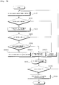
- an actuator displacement measuring system in an electro-hydraulic system for a construction machine having an electric motor 10, a hydraulic pump 11 driven by the electric motor 10, a hydraulic actuator (hereinafter referred to as a "hydraulic cylinder") 12 connected to the hydraulic pump 11, a load holding valve 13, 14 installed in a flow path between the hydraulic pump 11 and the hydraulic cylinder 12, a relief valve 15, 16 installed in a branch flow path connected in parallel to the flow path, and a controller 17 controlling driving of the electric motor 10,
- the actuator displacement measuring system includes controlling the driving of the electric motor 10 according to a control signal from the controller 17 (S100); determining whether the electric motor 10 is driven (S200); if the electric motor 10 is driven, calculating a flow rate Q of the hydraulic pump 11 (S300); determining whether a displacement value of the hydraulic cylinder 12 that is always detected by a detection signal input from second and third sensors 21 and 22 for sensing positions to the controller 17 deviates from a zero value (in
- an accumulated error of displacement values of the hydraulic cylinder 12, which are calculated by detection signals input from first to third sensors 19, 21, and 22 for sensing positions that are mounted on a hydraulic cylinder tube to the controller 17 during a stroke end of a piston 18 of the hydraulic cylinder 12, is removed, and the displacement value of the hydraulic cylinder 12 is reset to a zero value when the first sensor 19 coincides with any one of the second and third sensors 21 and 22.
- the hydraulic pump 11 may be composed of a fixed displacement hydraulic pump.
- unexplained reference numeral 23 denotes an energy storage system
- 24 denotes an AD converter
- 25 and 26 denote pressure sensors detecting the pressure of the hydraulic system and transmitting a detection signal to the controller 17.
- electric energy of an AC voltage of the energy storage system 23 is converted into a DC voltage by the AD converter 24, and the converted DC voltage is supplied to the electric motor 10 to drive the electric motor 10.
- the electric motor 10 is driven by a control signal from the controller 17, and the electric motor 10 drives the hydraulic pump 11.
- the speed V of the hydraulic cylinder 12 is determined from the correlation between the supply flow rate Q of the hydraulic pump 11 and the sectional area A of the hydraulic cylinder 12.
- the driving of the electric motor 10 is controlled by the control signal from the controller 17.
- the supply flow rate Q of the hydraulic pump 11 is calculated using the speed value of the electric motor 10 (the rotating speed of the electric motor is detected by a rotating speed detector (not illustrated)) and the capacity value of the hydraulic pump 11.
- the detection signals that are detected by the second and third sensors 21 and 22 for sensing positions mounted on the hydraulic cylinder 12 are always input to the controller 17. If the first sensor 19 for sensing positions that is mounted on the hydraulic cylinder piston 18 comes in contact with any one of the second and third sensors 21 and 22 for sensing positions that are mounted on the hydraulic cylinder tube (if a limit switch is in an on state), the hydraulic cylinder piston 18 is in the stroke end state, and the controller 17 sets the displacement D of the hydraulic cylinder 12 to a zero value (initial value). Through this, the accumulated error of displacement values of the hydraulic cylinder 12, which is continuously accumulated due to the use of an integrator in a process of calculating the displacement of the hydraulic cylinder 12, can be removed. That is, by resetting the initial value at a specific position, the precision in measuring the displacement of the hydraulic cylinder 12 can be enhanced.
- the process proceeds to S600C, while if the limit switch is in an off state (if the first sensor 19 for sensing positions does not come in contact with the second and third sensors 21 and 22 for sensing positions), the process proceeds to S500.
- the set pressure value of the relief valve 15, 16 is compared with the pressure value of the hydraulic system that is detected by the pressure sensor 25, 26. If the pressure value of the hydraulic system is larger than or equal to the pressure value of the relief valve 15, 16, the process proceeds to S600B, while if the pressure value of the hydraulic system is smaller than the pressure value of the relief valve 15, 16, the process proceeds to S600A.
- the displacement value of the hydraulic cylinder 12 is set to the previous value. This is because when the detected pressure of the hydraulic system is higher than the set pressure of the relief valve 15, 16, all the hydraulic fluid that is discharged from the hydraulic pump 11 returns to a hydraulic tank T via the relief valve 15, 16, and thus the hydraulic cylinder 12 is not driven. Accordingly, by keeping the displacement value of the hydraulic cylinder 12 as the previous value, the displacement value of the hydraulic cylinder 12 can be calculated.
- the displacement D of the hydraulic cylinder 12 is calculated using the rotating speed of the electric motor 10, the sectional area of the hydraulic cylinder 12, and the supply flow rate of the hydraulic pump 11.
- the displacement of the hydraulic cylinder is detected using the characteristics of the electro-hydraulic system, and thus a separate displacement sensor is unnecessary. Further, due to the accuracy of the values of displacement detection of the hydraulic cylinder, the driving of the hydraulic cylinder can be precisely controlled.
Landscapes
- Engineering & Computer Science (AREA)
- General Engineering & Computer Science (AREA)
- Mining & Mineral Resources (AREA)
- Civil Engineering (AREA)
- Structural Engineering (AREA)
- Physics & Mathematics (AREA)
- Fluid Mechanics (AREA)
- Mechanical Engineering (AREA)
- Chemical & Material Sciences (AREA)
- Analytical Chemistry (AREA)
- Fluid-Pressure Circuits (AREA)
- Operation Control Of Excavators (AREA)
Claims (3)
- Ein elektrohydraulisches System für eine Baumaschine mit einem Hydraulikzylinderverschiebungsmesssystem, das einen Elektromotor (10), eine durch den Elektromotor (10) angetriebene Hydraulikpumpe (11), einen mit der Hydraulikpumpe (11) verbundenen Hydraulikzylinder (12), ein Überdruckventil (15, 16), das in einem Zweigdurchflussweg installiert ist, der parallel zu dem Durchflussweg geschaltet ist, und eine Steuerung (17), die das Antreiben des Elektromotors (10) steuert, umfasst,
dadurch gekennzeichnet, dass das System ferner folgende Merkmale aufweist:ein Lasthalteventil, das in einem Durchflussweg zwischen der Hydraulikpumpe und dem Hydraulikzylinder (12) installiert ist;einen ersten Sensor (19) zum Erfassen von Positionen, der an einem Kolben (18) des Hydraulikzylinders (12) angebracht ist; undeinen zweiten und einen dritten Sensor (21, 22) zum Erfassen von Positionen, die an einem Hydraulikzylinderrohr (20) angebracht sind, während eines Hubendes des Hydraulikzylinders (12);wobei das Verschiebungsmesssystem folgende Schritte aufweist:Steuern des Antriebs des Elektromotors (10) gemäß einem Steuersignal von der Steuerung (17);Bestimmen, ob der Elektromotor (10) angetrieben wird, und falls der Elektromotor (10) angetrieben wird, Berechnen einer Durchflussrate der Hydraulikpumpe (11);Bestimmen, ob ein Verschiebungswert des Hydraulikzylinders (12), der immer durch ein Detektionssignal von den Positionsdetektionssensoren (19, 21, 22) an die Steuerung (19) detektiert wird, von einem Nullwert abweicht, der als Referenzposition eingestellt ist;Bestimmen, ob ein eingestellter Druckwert des Überdruckventils (15, 16) größer als ein oder gleich einem gemessenen Druckwert des Hydrauliksystems ist, falls der Hydraulikzylinderverschiebungswert von dem Nullwert abweicht;Einstellen des Hydraulikzylinderverschiebungswerts auf einen vorherigen Wert, falls der Druckwert des Hydrauliksystems größer als der oder gleich dem Druckwert des Überdruckventils (15, 16) ist, und Berechnen des Hydraulikzylinderverschiebungswerts unter Verwendung einer Drehzahl des Elektromotors (10), einer Querschnittfläche des Hydraulikzylinders (12) und einer Versorgungsdurchflussrate der Hydraulikpumpe (11), falls der Druckwert des Hydrauliksystems kleiner als der Druckwert des Überdruckventils (15, 16) ist; undBeenden der Berechnung nach dem Speichern des bisher berechneten Hydraulikzylinderverschiebungswerts in der Steuerung (17), falls eine Abschaltanforderung des Hydrauliksystems eingegeben wird, und Übergehen zu einer Anfangsstufe, falls die Abschaltanforderung des Hydrauliksystems nicht eingegeben wird,wobei ein aufgelaufener Fehler von Verschiebungswerten des Hydraulikzylinders (12), die durch Detektionssignale an die Steuerung (17) berechnet werden, die von dem zweiten und dem dritten Sensor (21, 22) eingegeben werden, beseitigt wird und der Verschiebungswert des Hydraulikzylinders (12) auf den Nullwert zurückgesetzt wird, wenn der erste Sensor (19) zum Erfassen von Positionen mit dem zweiten oder dem dritten Sensor (21, 22) zum Erfassen von Positionen während eines Hubendes des Hydraulikzylinders (12) in Kontakt kommt. - Das elektrohydraulische System gemäß Anspruch 1, bei dem der Verschiebungswert D des Hydraulikzylinders (12) mittels D = ∫Vdt = ∫(Q/A)dt berechnet wird (wobei V eine Antriebsgeschwindigkeit des Hydraulikzylinders ist, Q eine Durchflussrate der Hydraulikpumpe ist und A eine Querschnittsfläche des Hydraulikzylinders ist).
- Das elektrohydraulische System gemäß Anspruch 1, bei dem die Hydraulikpumpe (11) aus einer feststehenden Verschiebungshydraulikpumpe gebildet ist.
Applications Claiming Priority (1)
| Application Number | Priority Date | Filing Date | Title |
|---|---|---|---|
| PCT/KR2011/007534 WO2013054954A1 (ko) | 2011-10-11 | 2011-10-11 | 건설기계의 전자 유압시스템에서의 액츄에이터 변위 측정시스템 |
Publications (3)
| Publication Number | Publication Date |
|---|---|
| EP2767720A1 EP2767720A1 (de) | 2014-08-20 |
| EP2767720A4 EP2767720A4 (de) | 2015-06-24 |
| EP2767720B1 true EP2767720B1 (de) | 2019-04-03 |
Family
ID=48081993
Family Applications (1)
| Application Number | Title | Priority Date | Filing Date |
|---|---|---|---|
| EP11873826.9A Not-in-force EP2767720B1 (de) | 2011-10-11 | 2011-10-11 | Elektrohydraulischessystem für eine baumaschine |
Country Status (6)
| Country | Link |
|---|---|
| US (1) | US9506225B2 (de) |
| EP (1) | EP2767720B1 (de) |
| JP (1) | JP5916870B2 (de) |
| KR (1) | KR101889779B1 (de) |
| CN (1) | CN103857927B (de) |
| WO (1) | WO2013054954A1 (de) |
Cited By (1)
| Publication number | Priority date | Publication date | Assignee | Title |
|---|---|---|---|---|
| WO2024184063A1 (de) * | 2023-03-03 | 2024-09-12 | Hydac Systems & Services Gmbh | Verfahren zum ansteuern eines fluidischen aktors nebst vorrichtung zum durchführen des verfahrens |
Families Citing this family (36)
| Publication number | Priority date | Publication date | Assignee | Title |
|---|---|---|---|---|
| KR101545677B1 (ko) * | 2011-12-16 | 2015-08-19 | 볼보 컨스트럭션 이큅먼트 에이비 | 전자 유압 액츄에이터 시스템을 이용한 운전자 자가 튜닝 방법 |
| WO2015131196A1 (en) | 2014-02-28 | 2015-09-03 | Project Phoenix, LLC | Pump integrated with two independently driven prime movers |
| EP3149342B1 (de) | 2014-06-02 | 2020-04-15 | Project Phoenix LLC | Linearaktuatoranordnung und -system |
| KR102316426B1 (ko) | 2014-07-22 | 2021-10-21 | 프로젝트 피닉스, 엘엘씨 | 독립적으로 구동되는 2개의 원동기와 통합된 외부 기어 펌프 |
| US9562547B2 (en) | 2014-08-29 | 2017-02-07 | Abb Schweiz Ag | Electric hydraulic actuator |
| US9682473B2 (en) | 2014-08-29 | 2017-06-20 | Abb Schweiz Ag | Electric fluidic rotary joint actuator with pump |
| US10072676B2 (en) | 2014-09-23 | 2018-09-11 | Project Phoenix, LLC | System to pump fluid and control thereof |
| EP3896314B1 (de) | 2014-10-06 | 2024-03-27 | Project Phoenix, LLC | Linearaktuatoranordnung und -system |
| US11137000B2 (en) * | 2014-10-10 | 2021-10-05 | MEA Inc. | Self-contained energy efficient hydraulic actuator system |
| US9835217B2 (en) | 2015-02-12 | 2017-12-05 | Nhk Spring Co., Ltd. | Coil spring modeling apparatus and method utilizing a torsion detection to control an actuator unit |
| US9811067B2 (en) * | 2015-02-12 | 2017-11-07 | Nhk Spring Co., Ltd. | Coil spring modeling apparatus and method of the same |
| JP2016147754A (ja) * | 2015-02-13 | 2016-08-18 | 株式会社タダノ | アクチュエータ制御装置及び作業車両 |
| JP6448403B2 (ja) * | 2015-02-17 | 2019-01-09 | 住友精密工業株式会社 | 航空機の脚揚降用電動油圧アクチュエータシステム |
| TWI712744B (zh) | 2015-09-02 | 2020-12-11 | 美商鳳凰計劃股份有限公司 | 泵送流體之系統及其控制 |
| EP3344853B1 (de) | 2015-09-02 | 2020-11-04 | Project Phoenix LLC | System zum pumpen einer flüssigkeit und steuerung dafür |
| CN106640844B (zh) * | 2015-10-30 | 2018-02-09 | 中石化石油工程技术服务有限公司 | 旋转导向液压系统电磁阀组测试装置 |
| DE102016109801A1 (de) * | 2016-05-27 | 2017-11-30 | Still Gmbh | Verfahren zur Feststellung der Endlagenposition eines Hydraulikzylinders einer Arbeitshydraulik einer mobilen Arbeitsmaschine, insbesondere eines Flurförderzeugs |
| CN106246617B (zh) * | 2016-08-24 | 2018-05-04 | 浙江工业大学 | 往复机械的高性能组合密封圈性能测试系统 |
| KR101943396B1 (ko) * | 2017-09-04 | 2019-01-30 | 하이드로텍(주) | 복동실린더용 유압구동시스템 |
| KR101940278B1 (ko) * | 2017-09-04 | 2019-01-21 | 하이드로텍(주) | 압력보상기능을 갖는 유압구동시스템 |
| CN108071629B (zh) * | 2017-12-14 | 2020-06-19 | 北京航天发射技术研究所 | 一种双多级油缸同步升降液压系统 |
| CN108757642B (zh) * | 2018-05-30 | 2019-11-05 | 凤阳县万明电子信息科技有限公司 | 一种用于液压缸生产流水线的放置测试装置 |
| CN109183892B (zh) * | 2018-09-21 | 2021-05-14 | 柳州柳工挖掘机有限公司 | 工作装置驱动油路及挖掘机 |
| CN110905869A (zh) * | 2019-12-16 | 2020-03-24 | 广东志成电液科技有限公司 | 具备自定位功能的总线式电液缸及其控制方法 |
| JP7306699B2 (ja) * | 2020-04-03 | 2023-07-11 | 株式会社ササキコーポレーション | 作業機 |
| JP7265777B2 (ja) * | 2020-04-03 | 2023-04-27 | 株式会社ササキコーポレーション | 作業機 |
| DE102020207864A1 (de) * | 2020-06-25 | 2021-12-30 | Robert Bosch Gesellschaft mit beschränkter Haftung | Verfahren zum Betreiben eines hydraulischen Antriebs |
| EP4179211A1 (de) | 2020-07-08 | 2023-05-17 | Project Phoenix, LLC | Dynamische steuerung von zahnrädern in einer zahnradpumpe mit einer antriebskonfiguration |
| WO2022011022A1 (en) | 2020-07-08 | 2022-01-13 | Project Phoenix, LLC | Dynamic control of gears in a gear pump having a drive-drive configuration |
| IT202100027911A1 (it) * | 2021-11-02 | 2023-05-02 | Jp Tech Srl | Metodo e sistema per mantenimento e controllo di posizione anche in assenza di alimentazione. |
| DE102022211393A1 (de) * | 2022-10-27 | 2024-05-02 | Robert Bosch Gesellschaft mit beschränkter Haftung | Hydraulische Anordnung mit Lasthaltefunktion und Steuerungsverfahren der hydraulischen Anordnung |
| CN115573967B (zh) * | 2022-12-07 | 2023-03-21 | 太原理工大学 | 阀控液压缸速度位置复合控制系统及流量控制方法 |
| DE102024101061A1 (de) * | 2024-01-15 | 2025-07-17 | Liebherr-Aerospace Lindenberg Gmbh | Elektro-hydrostatische Aktuatoranordnung mit Entlüftung |
| DE102024001777A1 (de) * | 2024-05-31 | 2025-12-04 | HYDAC KineSys GmbH | Verfahren zur Positionierung eines Aktors |
| CN118515200B (zh) * | 2024-07-23 | 2024-09-27 | 中联重科股份有限公司 | 臂架变幅系统、多液压执行器同步控制方法及作业机械 |
| CN119288950B (zh) * | 2024-12-16 | 2025-04-18 | 浙江大学 | 高稳定可控液压旋转执行器低速稳定性能测试装置及方法 |
Family Cites Families (16)
| Publication number | Priority date | Publication date | Assignee | Title |
|---|---|---|---|---|
| JPS6323005A (ja) * | 1986-07-15 | 1988-01-30 | Japan Steel Works Ltd:The | 射出成形機の射出装置の移動量制御方法 |
| JP2580483B2 (ja) * | 1994-02-18 | 1997-02-12 | 株式会社小松製作所 | 静油圧−機械式変速機の制御装置 |
| JPH116501A (ja) * | 1997-06-18 | 1999-01-12 | Fujitsu Ltd | シリンダ制御方法及び半導体製造装置の制御方法 |
| AT409656B (de) * | 1999-10-18 | 2002-10-25 | Hoerbiger Hydraulik | Hydraulische betätigungsanordnung |
| JP4578017B2 (ja) | 2001-04-26 | 2010-11-10 | 住友建機株式会社 | 油圧シリンダ駆動装置 |
| US7114430B2 (en) * | 2004-09-30 | 2006-10-03 | Caterpillar Inc. | Adaptive position determining system for hydraulic cylinder |
| KR200377929Y1 (ko) * | 2004-10-05 | 2005-03-11 | 일림유압 주식회사 | 아이피엠 모터와 피아이디제어 기능이 내장된 인버터를 이용한 에너지 절약형 유압유니트 |
| US7240604B2 (en) * | 2005-07-29 | 2007-07-10 | Caterpillar Inc | Electro-hydraulic metering valve with integral flow control |
| SE531309C2 (sv) * | 2006-01-16 | 2009-02-17 | Volvo Constr Equip Ab | Styrsystem för en arbetsmaskin och förfarande för styrning av en hydraulcylinder hos en arbetsmaskin |
| CN100424361C (zh) * | 2006-03-07 | 2008-10-08 | 太原理工大学 | 闭式电液控制系统 |
| JP2008151299A (ja) * | 2006-12-19 | 2008-07-03 | Riken Kiki Kk | サーボ弁による油圧シリンダの制御装置 |
| DE102009023168A1 (de) | 2009-05-29 | 2010-12-02 | Festo Ag & Co. Kg | Positionsmesseinrichtung zur Erfassung der Position wenigstens eines Stellglieds eines fluidischen Systems ohne Positionssensor |
| FR2946401B1 (fr) | 2009-06-03 | 2015-10-16 | Airbus France | Actionneur a puissance electrique et procede de commande d'un tel actionneur. |
| CN101718291B (zh) * | 2009-11-13 | 2012-12-19 | 浙江工业大学 | 大流量高频电液激振控制阀驱动系统 |
| CN102092662B (zh) * | 2010-12-15 | 2012-12-19 | 三一集团有限公司 | 举升液压系统及具有该液压系统的举升机械 |
| US8944103B2 (en) * | 2011-08-31 | 2015-02-03 | Caterpillar Inc. | Meterless hydraulic system having displacement control valve |
-
2011
- 2011-10-11 EP EP11873826.9A patent/EP2767720B1/de not_active Not-in-force
- 2011-10-11 WO PCT/KR2011/007534 patent/WO2013054954A1/ko not_active Ceased
- 2011-10-11 US US14/349,153 patent/US9506225B2/en not_active Expired - Fee Related
- 2011-10-11 JP JP2014535627A patent/JP5916870B2/ja active Active
- 2011-10-11 CN CN201180074006.8A patent/CN103857927B/zh not_active Expired - Fee Related
- 2011-10-11 KR KR1020147007836A patent/KR101889779B1/ko not_active Expired - Fee Related
Non-Patent Citations (1)
| Title |
|---|
| None * |
Cited By (1)
| Publication number | Priority date | Publication date | Assignee | Title |
|---|---|---|---|---|
| WO2024184063A1 (de) * | 2023-03-03 | 2024-09-12 | Hydac Systems & Services Gmbh | Verfahren zum ansteuern eines fluidischen aktors nebst vorrichtung zum durchführen des verfahrens |
Also Published As
| Publication number | Publication date |
|---|---|
| US20140230643A1 (en) | 2014-08-21 |
| EP2767720A1 (de) | 2014-08-20 |
| WO2013054954A1 (ko) | 2013-04-18 |
| US9506225B2 (en) | 2016-11-29 |
| KR101889779B1 (ko) | 2018-09-28 |
| JP2014534394A (ja) | 2014-12-18 |
| EP2767720A4 (de) | 2015-06-24 |
| CN103857927B (zh) | 2016-08-17 |
| JP5916870B2 (ja) | 2016-05-11 |
| KR20140079381A (ko) | 2014-06-26 |
| CN103857927A (zh) | 2014-06-11 |
Similar Documents
| Publication | Publication Date | Title |
|---|---|---|
| EP2767720B1 (de) | Elektrohydraulischessystem für eine baumaschine | |
| US8718880B2 (en) | Hydraulic system calibration method and apparatus | |
| KR102490904B1 (ko) | 건설 기계 | |
| US9303659B2 (en) | Method of controlling the flow rate of a variable capacity hydraulic pump for a construction apparatus | |
| US8838349B2 (en) | Drive control system for construction machinery | |
| US8950180B2 (en) | Hybrid construction machine | |
| JP4574406B2 (ja) | 油圧作業機械における油圧シリンダのストローク位置計測装置 | |
| US20240200581A1 (en) | Velocity And Position Compound Control System For Pump-Valve Dual-Source Driven Hydraulic Cylinder | |
| KR101693386B1 (ko) | 편로드 유압실린더용 적응 제어식 유압장치 | |
| KR20090092616A (ko) | 유압실린더의 위치에너지 회생용 유압회로 | |
| US10767345B2 (en) | Device and method for controlling work machine | |
| JP2004212128A (ja) | 油圧装置の異常監視方法 | |
| JP2008133848A (ja) | アキュムレータの蓄積液量計測システム | |
| JP5511009B2 (ja) | 可変容量型油圧モータの制御装置 | |
| WO2023068115A1 (ja) | 目詰まり算定システム、目詰まり算定方法、および目詰まり算定プログラム | |
| JP2013072454A (ja) | 油圧ユニット | |
| JP5398647B2 (ja) | ハイブリッド式建設機械 | |
| JP2008163594A (ja) | 建設機械の制御装置 | |
| JP5563173B1 (ja) | 液圧装置および液圧装置の制御方法 | |
| JP2001240381A (ja) | ブーム伸縮用シリンダの保持圧補償装置 | |
| EP4332310A1 (de) | Verfahren zur überwachung des betriebs eines hydrauliksystems | |
| KR101177179B1 (ko) | 직동력 유압 액츄에이터 구동 시스템 | |
| EP3763949B1 (de) | Verfahren zur steuerung eines hydrauliksystems, hydrauliksystem und kran | |
| CN117345703A (zh) | 液压传动系统及液压缸无杆腔和有杆腔工作压力计算方法 | |
| JP2006220243A (ja) | 液圧アクチュエーター制御方法及びその装置 |
Legal Events
| Date | Code | Title | Description |
|---|---|---|---|
| PUAI | Public reference made under article 153(3) epc to a published international application that has entered the european phase |
Free format text: ORIGINAL CODE: 0009012 |
|
| 17P | Request for examination filed |
Effective date: 20140331 |
|
| AK | Designated contracting states |
Kind code of ref document: A1 Designated state(s): AL AT BE BG CH CY CZ DE DK EE ES FI FR GB GR HR HU IE IS IT LI LT LU LV MC MK MT NL NO PL PT RO RS SE SI SK SM TR |
|
| DAX | Request for extension of the european patent (deleted) | ||
| RA4 | Supplementary search report drawn up and despatched (corrected) |
Effective date: 20150522 |
|
| RIC1 | Information provided on ipc code assigned before grant |
Ipc: F15B 15/28 20060101ALI20150518BHEP Ipc: E02F 9/22 20060101ALI20150518BHEP Ipc: E02F 9/20 20060101ALI20150518BHEP Ipc: F15B 21/08 20060101ALI20150518BHEP Ipc: E02F 9/26 20060101ALI20150518BHEP Ipc: F15B 19/00 20060101AFI20150518BHEP Ipc: G01B 21/00 20060101ALI20150518BHEP |
|
| 17Q | First examination report despatched |
Effective date: 20160727 |
|
| STAA | Information on the status of an ep patent application or granted ep patent |
Free format text: STATUS: EXAMINATION IS IN PROGRESS |
|
| GRAP | Despatch of communication of intention to grant a patent |
Free format text: ORIGINAL CODE: EPIDOSNIGR1 |
|
| STAA | Information on the status of an ep patent application or granted ep patent |
Free format text: STATUS: GRANT OF PATENT IS INTENDED |
|
| INTG | Intention to grant announced |
Effective date: 20181015 |
|
| GRAS | Grant fee paid |
Free format text: ORIGINAL CODE: EPIDOSNIGR3 |
|
| GRAA | (expected) grant |
Free format text: ORIGINAL CODE: 0009210 |
|
| STAA | Information on the status of an ep patent application or granted ep patent |
Free format text: STATUS: THE PATENT HAS BEEN GRANTED |
|
| AK | Designated contracting states |
Kind code of ref document: B1 Designated state(s): AL AT BE BG CH CY CZ DE DK EE ES FI FR GB GR HR HU IE IS IT LI LT LU LV MC MK MT NL NO PL PT RO RS SE SI SK SM TR |
|
| REG | Reference to a national code |
Ref country code: GB Ref legal event code: FG4D |
|
| REG | Reference to a national code |
Ref country code: CH Ref legal event code: EP Ref country code: AT Ref legal event code: REF Ref document number: 1116087 Country of ref document: AT Kind code of ref document: T Effective date: 20190415 |
|
| REG | Reference to a national code |
Ref country code: DE Ref legal event code: R096 Ref document number: 602011057854 Country of ref document: DE |
|
| REG | Reference to a national code |
Ref country code: IE Ref legal event code: FG4D |
|
| REG | Reference to a national code |
Ref country code: NL Ref legal event code: MP Effective date: 20190403 |
|
| REG | Reference to a national code |
Ref country code: LT Ref legal event code: MG4D |
|
| REG | Reference to a national code |
Ref country code: AT Ref legal event code: MK05 Ref document number: 1116087 Country of ref document: AT Kind code of ref document: T Effective date: 20190403 |
|
| PG25 | Lapsed in a contracting state [announced via postgrant information from national office to epo] |
Ref country code: NL Free format text: LAPSE BECAUSE OF FAILURE TO SUBMIT A TRANSLATION OF THE DESCRIPTION OR TO PAY THE FEE WITHIN THE PRESCRIBED TIME-LIMIT Effective date: 20190403 |
|
| PG25 | Lapsed in a contracting state [announced via postgrant information from national office to epo] |
Ref country code: CZ Free format text: LAPSE BECAUSE OF FAILURE TO SUBMIT A TRANSLATION OF THE DESCRIPTION OR TO PAY THE FEE WITHIN THE PRESCRIBED TIME-LIMIT Effective date: 20190403 Ref country code: PT Free format text: LAPSE BECAUSE OF FAILURE TO SUBMIT A TRANSLATION OF THE DESCRIPTION OR TO PAY THE FEE WITHIN THE PRESCRIBED TIME-LIMIT Effective date: 20190803 Ref country code: FI Free format text: LAPSE BECAUSE OF FAILURE TO SUBMIT A TRANSLATION OF THE DESCRIPTION OR TO PAY THE FEE WITHIN THE PRESCRIBED TIME-LIMIT Effective date: 20190403 Ref country code: AL Free format text: LAPSE BECAUSE OF FAILURE TO SUBMIT A TRANSLATION OF THE DESCRIPTION OR TO PAY THE FEE WITHIN THE PRESCRIBED TIME-LIMIT Effective date: 20190403 Ref country code: HR Free format text: LAPSE BECAUSE OF FAILURE TO SUBMIT A TRANSLATION OF THE DESCRIPTION OR TO PAY THE FEE WITHIN THE PRESCRIBED TIME-LIMIT Effective date: 20190403 Ref country code: SE Free format text: LAPSE BECAUSE OF FAILURE TO SUBMIT A TRANSLATION OF THE DESCRIPTION OR TO PAY THE FEE WITHIN THE PRESCRIBED TIME-LIMIT Effective date: 20190403 Ref country code: NO Free format text: LAPSE BECAUSE OF FAILURE TO SUBMIT A TRANSLATION OF THE DESCRIPTION OR TO PAY THE FEE WITHIN THE PRESCRIBED TIME-LIMIT Effective date: 20190703 Ref country code: ES Free format text: LAPSE BECAUSE OF FAILURE TO SUBMIT A TRANSLATION OF THE DESCRIPTION OR TO PAY THE FEE WITHIN THE PRESCRIBED TIME-LIMIT Effective date: 20190403 Ref country code: LT Free format text: LAPSE BECAUSE OF FAILURE TO SUBMIT A TRANSLATION OF THE DESCRIPTION OR TO PAY THE FEE WITHIN THE PRESCRIBED TIME-LIMIT Effective date: 20190403 |
|
| PG25 | Lapsed in a contracting state [announced via postgrant information from national office to epo] |
Ref country code: BG Free format text: LAPSE BECAUSE OF FAILURE TO SUBMIT A TRANSLATION OF THE DESCRIPTION OR TO PAY THE FEE WITHIN THE PRESCRIBED TIME-LIMIT Effective date: 20190703 Ref country code: GR Free format text: LAPSE BECAUSE OF FAILURE TO SUBMIT A TRANSLATION OF THE DESCRIPTION OR TO PAY THE FEE WITHIN THE PRESCRIBED TIME-LIMIT Effective date: 20190704 Ref country code: PL Free format text: LAPSE BECAUSE OF FAILURE TO SUBMIT A TRANSLATION OF THE DESCRIPTION OR TO PAY THE FEE WITHIN THE PRESCRIBED TIME-LIMIT Effective date: 20190403 Ref country code: RS Free format text: LAPSE BECAUSE OF FAILURE TO SUBMIT A TRANSLATION OF THE DESCRIPTION OR TO PAY THE FEE WITHIN THE PRESCRIBED TIME-LIMIT Effective date: 20190403 Ref country code: LV Free format text: LAPSE BECAUSE OF FAILURE TO SUBMIT A TRANSLATION OF THE DESCRIPTION OR TO PAY THE FEE WITHIN THE PRESCRIBED TIME-LIMIT Effective date: 20190403 |
|
| PG25 | Lapsed in a contracting state [announced via postgrant information from national office to epo] |
Ref country code: IS Free format text: LAPSE BECAUSE OF FAILURE TO SUBMIT A TRANSLATION OF THE DESCRIPTION OR TO PAY THE FEE WITHIN THE PRESCRIBED TIME-LIMIT Effective date: 20190803 Ref country code: AT Free format text: LAPSE BECAUSE OF FAILURE TO SUBMIT A TRANSLATION OF THE DESCRIPTION OR TO PAY THE FEE WITHIN THE PRESCRIBED TIME-LIMIT Effective date: 20190403 |
|
| REG | Reference to a national code |
Ref country code: DE Ref legal event code: R097 Ref document number: 602011057854 Country of ref document: DE |
|
| PG25 | Lapsed in a contracting state [announced via postgrant information from national office to epo] |
Ref country code: RO Free format text: LAPSE BECAUSE OF FAILURE TO SUBMIT A TRANSLATION OF THE DESCRIPTION OR TO PAY THE FEE WITHIN THE PRESCRIBED TIME-LIMIT Effective date: 20190403 Ref country code: EE Free format text: LAPSE BECAUSE OF FAILURE TO SUBMIT A TRANSLATION OF THE DESCRIPTION OR TO PAY THE FEE WITHIN THE PRESCRIBED TIME-LIMIT Effective date: 20190403 Ref country code: DK Free format text: LAPSE BECAUSE OF FAILURE TO SUBMIT A TRANSLATION OF THE DESCRIPTION OR TO PAY THE FEE WITHIN THE PRESCRIBED TIME-LIMIT Effective date: 20190403 Ref country code: SK Free format text: LAPSE BECAUSE OF FAILURE TO SUBMIT A TRANSLATION OF THE DESCRIPTION OR TO PAY THE FEE WITHIN THE PRESCRIBED TIME-LIMIT Effective date: 20190403 |
|
| PLBE | No opposition filed within time limit |
Free format text: ORIGINAL CODE: 0009261 |
|
| STAA | Information on the status of an ep patent application or granted ep patent |
Free format text: STATUS: NO OPPOSITION FILED WITHIN TIME LIMIT |
|
| PG25 | Lapsed in a contracting state [announced via postgrant information from national office to epo] |
Ref country code: SM Free format text: LAPSE BECAUSE OF FAILURE TO SUBMIT A TRANSLATION OF THE DESCRIPTION OR TO PAY THE FEE WITHIN THE PRESCRIBED TIME-LIMIT Effective date: 20190403 Ref country code: IT Free format text: LAPSE BECAUSE OF FAILURE TO SUBMIT A TRANSLATION OF THE DESCRIPTION OR TO PAY THE FEE WITHIN THE PRESCRIBED TIME-LIMIT Effective date: 20190403 |
|
| 26N | No opposition filed |
Effective date: 20200106 |
|
| PG25 | Lapsed in a contracting state [announced via postgrant information from national office to epo] |
Ref country code: TR Free format text: LAPSE BECAUSE OF FAILURE TO SUBMIT A TRANSLATION OF THE DESCRIPTION OR TO PAY THE FEE WITHIN THE PRESCRIBED TIME-LIMIT Effective date: 20190403 |
|
| REG | Reference to a national code |
Ref country code: DE Ref legal event code: R119 Ref document number: 602011057854 Country of ref document: DE |
|
| PG25 | Lapsed in a contracting state [announced via postgrant information from national office to epo] |
Ref country code: SI Free format text: LAPSE BECAUSE OF FAILURE TO SUBMIT A TRANSLATION OF THE DESCRIPTION OR TO PAY THE FEE WITHIN THE PRESCRIBED TIME-LIMIT Effective date: 20190403 Ref country code: MC Free format text: LAPSE BECAUSE OF FAILURE TO SUBMIT A TRANSLATION OF THE DESCRIPTION OR TO PAY THE FEE WITHIN THE PRESCRIBED TIME-LIMIT Effective date: 20190403 |
|
| REG | Reference to a national code |
Ref country code: CH Ref legal event code: PL |
|
| PG25 | Lapsed in a contracting state [announced via postgrant information from national office to epo] |
Ref country code: LI Free format text: LAPSE BECAUSE OF NON-PAYMENT OF DUE FEES Effective date: 20191031 Ref country code: LU Free format text: LAPSE BECAUSE OF NON-PAYMENT OF DUE FEES Effective date: 20191011 Ref country code: CH Free format text: LAPSE BECAUSE OF NON-PAYMENT OF DUE FEES Effective date: 20191031 Ref country code: DE Free format text: LAPSE BECAUSE OF NON-PAYMENT OF DUE FEES Effective date: 20200501 |
|
| REG | Reference to a national code |
Ref country code: BE Ref legal event code: MM Effective date: 20191031 |
|
| PG25 | Lapsed in a contracting state [announced via postgrant information from national office to epo] |
Ref country code: BE Free format text: LAPSE BECAUSE OF NON-PAYMENT OF DUE FEES Effective date: 20191031 |
|
| GBPC | Gb: european patent ceased through non-payment of renewal fee |
Effective date: 20191011 |
|
| PG25 | Lapsed in a contracting state [announced via postgrant information from national office to epo] |
Ref country code: FR Free format text: LAPSE BECAUSE OF NON-PAYMENT OF DUE FEES Effective date: 20191031 Ref country code: IE Free format text: LAPSE BECAUSE OF NON-PAYMENT OF DUE FEES Effective date: 20191011 Ref country code: GB Free format text: LAPSE BECAUSE OF NON-PAYMENT OF DUE FEES Effective date: 20191011 |
|
| PG25 | Lapsed in a contracting state [announced via postgrant information from national office to epo] |
Ref country code: CY Free format text: LAPSE BECAUSE OF FAILURE TO SUBMIT A TRANSLATION OF THE DESCRIPTION OR TO PAY THE FEE WITHIN THE PRESCRIBED TIME-LIMIT Effective date: 20190403 |
|
| PG25 | Lapsed in a contracting state [announced via postgrant information from national office to epo] |
Ref country code: HU Free format text: LAPSE BECAUSE OF FAILURE TO SUBMIT A TRANSLATION OF THE DESCRIPTION OR TO PAY THE FEE WITHIN THE PRESCRIBED TIME-LIMIT; INVALID AB INITIO Effective date: 20111011 Ref country code: MT Free format text: LAPSE BECAUSE OF FAILURE TO SUBMIT A TRANSLATION OF THE DESCRIPTION OR TO PAY THE FEE WITHIN THE PRESCRIBED TIME-LIMIT Effective date: 20190403 |
|
| PG25 | Lapsed in a contracting state [announced via postgrant information from national office to epo] |
Ref country code: MK Free format text: LAPSE BECAUSE OF FAILURE TO SUBMIT A TRANSLATION OF THE DESCRIPTION OR TO PAY THE FEE WITHIN THE PRESCRIBED TIME-LIMIT Effective date: 20190403 |