EP2767365B1 - Compressed air nail gun with a manually actuated trigger and a contact sensor - Google Patents
Compressed air nail gun with a manually actuated trigger and a contact sensor Download PDFInfo
- Publication number
- EP2767365B1 EP2767365B1 EP13000843.6A EP13000843A EP2767365B1 EP 2767365 B1 EP2767365 B1 EP 2767365B1 EP 13000843 A EP13000843 A EP 13000843A EP 2767365 B1 EP2767365 B1 EP 2767365B1
- Authority
- EP
- European Patent Office
- Prior art keywords
- chamber
- pneumatic nailer
- valve
- control valve
- trigger
- Prior art date
- Legal status (The legal status is an assumption and is not a legal conclusion. Google has not performed a legal analysis and makes no representation as to the accuracy of the status listed.)
- Active
Links
- 238000000034 method Methods 0.000 claims description 18
- 230000008569 process Effects 0.000 claims description 16
- 230000001960 triggered effect Effects 0.000 claims description 15
- 230000000284 resting effect Effects 0.000 claims 1
- 230000000903 blocking effect Effects 0.000 description 30
- 238000013022 venting Methods 0.000 description 14
- 230000005540 biological transmission Effects 0.000 description 6
- 239000000523 sample Substances 0.000 description 6
- 238000009423 ventilation Methods 0.000 description 6
- 230000000977 initiatory effect Effects 0.000 description 5
- 230000004913 activation Effects 0.000 description 4
- 230000008878 coupling Effects 0.000 description 3
- 238000010168 coupling process Methods 0.000 description 3
- 238000005859 coupling reaction Methods 0.000 description 3
- 210000003746 feather Anatomy 0.000 description 3
- 238000013459 approach Methods 0.000 description 2
- 238000010276 construction Methods 0.000 description 2
- 230000001276 controlling effect Effects 0.000 description 2
- 238000006073 displacement reaction Methods 0.000 description 2
- 238000007789 sealing Methods 0.000 description 2
- 208000027418 Wounds and injury Diseases 0.000 description 1
- 230000001680 brushing effect Effects 0.000 description 1
- 230000006378 damage Effects 0.000 description 1
- 238000005553 drilling Methods 0.000 description 1
- 230000000694 effects Effects 0.000 description 1
- 208000014674 injury Diseases 0.000 description 1
- 230000007257 malfunction Effects 0.000 description 1
- 230000007246 mechanism Effects 0.000 description 1
- 230000001105 regulatory effect Effects 0.000 description 1
- 238000011144 upstream manufacturing Methods 0.000 description 1
Images


Classifications
-
- B—PERFORMING OPERATIONS; TRANSPORTING
- B25—HAND TOOLS; PORTABLE POWER-DRIVEN TOOLS; MANIPULATORS
- B25C—HAND-HELD NAILING OR STAPLING TOOLS; MANUALLY OPERATED PORTABLE STAPLING TOOLS
- B25C1/00—Hand-held nailing tools; Nail feeding devices
- B25C1/008—Safety devices
-
- B—PERFORMING OPERATIONS; TRANSPORTING
- B25—HAND TOOLS; PORTABLE POWER-DRIVEN TOOLS; MANIPULATORS
- B25C—HAND-HELD NAILING OR STAPLING TOOLS; MANUALLY OPERATED PORTABLE STAPLING TOOLS
- B25C1/00—Hand-held nailing tools; Nail feeding devices
- B25C1/04—Hand-held nailing tools; Nail feeding devices operated by fluid pressure, e.g. by air pressure
Definitions
- the invention relates to a Druck Kunststoffnagler with a working piston which is connected to a drive ram for driving a fastener and is applied in triggering a driving operation with compressed air, and a triggering device having a hand-actuated trigger and a touch sensor, wherein a common actuation of trigger and embarksetztler controls a first control valve and can trigger a driving operation.
- a pneumatic nailer is off US 3,964 . 659 a known.
- the touch sensor is a mechanical component which is held by a spring in a position overhanging a nozzle tool of the pneumatic nailer. If the air rod is attached to a workpiece, the touch sensor is displaced against the force of the spring until the muzzle tool rests against the workpiece. Only with such actuated embarkal Tartler a driving operation can be triggered. As a result, the known compressed air nailers offer a significantly improved security against unintentional release compared to devices without Aufsetzryler.
- Pneumatic nailer with a triggering device of the type described can be used in two different modes.
- the pneumatic nailer is first attached to a workpiece and thereby actuated the landing sensor. Subsequently, the trigger is actuated by hand, thereby triggering a single drive.
- the user In the so-called contact release, also referred to as touch, the user already holds the trigger while pressing the pneumatic nailer against the workpiece.
- the pneumatic nailer can be repeated in rapid sequence can be recognized, which allows a very fast working, especially if many fasteners must be driven for a sufficient attachment to the positioning accuracy only small demands are made.
- the contact triggering procedure entails an increased risk of injury.
- the user wishes to hold the manual trigger not only to place the pneumatic nailer on one and the same workpiece a few centimeters away from the last driven fastener, but also to move to another, possibly remotely located, workpiece, can be triggered in an accidental contact of an object or body part with the Aufsetzrler a driving operation.
- accidents can occur when a user (in disregard of important safety regulations) climbs a ladder with the pneumatic nailer while holding the trigger and accidentally brushing his leg with the touch probe.
- the pneumatic rodger is used to drive fasteners such as nails, pins or staples.
- the pneumatic nailer can have a magazine for the fastening means, from which in each case a fastening means is supplied to a receptacle of a necking tool of the pneumatic nailer.
- Both the drive and the control of the pneumatic nailer can be done completely pneumatically, a supply of electrical energy is therefore not required.
- a working piston of the pneumatic nailer When initiating a driving operation, a working piston of the pneumatic nailer is pressurized with compressed air.
- the working piston drives a Eintreibst Schemeel, which is connected to the working piston.
- the tappet meets a rear one End of the fastener in the receptacle of the muzzle tool and drives the fastener into the workpiece.
- the triggering device has a hand-operated trigger, for example in the form of a tilt or push button, and a touch sensor.
- the touch sensor may be a mechanical component that projects beyond the front end of the muzzle tool and is held in this position by a spring until the pneumatic nailer is attached to a workpiece. Then the Aufsetzfiihler is displaced against the direction of the spring force and against the driving direction. If this actuation of the touch probe together with an actuation of the trigger, a first control valve is actuated, whereby a driving operation can be triggered.
- the first control valve With a common actuation of trigger and Aufsetzr the first control valve is activated. If only one of the manually actuable release and the touch sensor is actuated, the first control valve will not be actuated. For a joint actuation of trigger and embarkateler it is sufficient if both the trigger and the touch sensor at a certain time both at the same time in the actuated state. This can be achieved on the one hand by a simultaneous operation, but also in any order. For example, as is typical for a single trigger, first the touchdown sensor can be actuated and then the manually operated trigger. Inêtaüslinate Malawi, however, the hand-actuated trigger and then the touch sensor can be operated first.
- the control of the first control valve can be achieved by a mechanical coupling of the manually operated release and the Aufsetztlers.
- a control pin of the first control valve only at a common Actuation of trigger and Aufsetzmler shifts and the first control valve thereby controlled.
- the activation of the first control valve can trigger a drive-in process. This is done in the invention, when the locking piston is in its rest position. On the other hand, when the blocking piston is in its blocking position, the triggering of a driving-in process is prevented when the first control valve is activated.
- a second control valve is actuated upon actuation of the manually actuable trigger independently of an actuation of the Aufsetzterlers.
- the second control valve is thus activated with each actuation of the trigger.
- a control pin of the second control valve may be arranged so that it is displaced from its rest position with each actuation of the trigger.
- a chamber is vented via a throttle or vented.
- venting is always meant that a connection is made to a compressed air leading room.
- ventilation is always meant that a connection to a non-pressurized space, in particular to the outside air, is produced.
- the chamber In a pneumatic nailer, the chamber is vented upon actuation of the second control valve, the pneumatic nailer on a line which the chamber connects with a compressed air leading room.
- the chamber In a pneumatic nailer, the chamber is vented when driving the second control valve, has the Pneumatic nailer on a line that connects the chamber with a non-pressurized space, especially with outside air.
- the throttle and the second control valve may be located in the respective line. If the chamber is to be ventilated, the chamber is depressurized in an initial state of the pneumatic nailer.
- the second control valve When the second control valve is actuated, air then flows via the throttle, so that the pressure in the chamber increases. If the chamber is to be vented, it is in an initial state of the pneumatic nailer under increased pressure. When the second control valve is actuated, the air in the chamber flows slowly through the throttle, so that the pressure in the chamber drops.
- the pressure in the chamber after a certain time passes a predetermined pressure threshold.
- the pressure exceeds the pressure threshold.
- the pressure drops below the predetermined pressure threshold.
- passing the predetermined pressure threshold causes the blocking piston to be displaced from a rest position to a blocking position. In the blocking position the triggering of a drive-in process is prevented.
- a driving operation after actuation of the trigger can be triggered only as long as the pressure in the chamber has not yet passed the predetermined pressure threshold. If the trigger is thus actuated for a longer period of time and the pressure in the chamber has consequently passed the pressure threshold, actuation of the attachment sensor does not trigger a driving operation, because this is prevented by the blocking piston which is then in the blocking position. It is thus prevented that a driving operation is triggered by a long after the actuation of the trigger taking place actuation of the touch sensor. This allows most unintentional Trips where the user has accidentally pressed the release button longer than necessary can be reliably prevented.
- the chamber is vented or vented when not actuated trigger. If the pneumatic nailer has a chamber which is vented when the second control valve is actuated, the chamber is vented when the trigger is not actuated. If the pneumatic nailer has a chamber which is vented when the second control valve is actuated, the chamber is ventilated when the trigger is not actuated.
- the venting or ventilation of the chamber when not actuated trigger can be done via the second control valve, possibly also via the second control valve and the throttle. In this case, the line used in the control of the second control valve for venting or venting the chamber, in which the throttle is arranged, also be used for venting or venting the chamber when not actuated trigger.
- the above-mentioned embodiment means that the desired pressure, which corresponds to an initial state of the pneumatic nailer, is established in the chamber when the trigger is not actuated.
- the compressed air nailer is always in its initial state after a certain time when the trigger is not actuated.
- the throttle is also in the line used for venting or venting the chamber when the trigger is not actuated, this initial state is only reached again after a certain time, if the pressure in the chamber had previously passed the predetermined pressure threshold.
- a further driving operation by pressing the Aufsetzers can only be done when the trigger has remained unactuated for a certain time.
- the pneumatic nailer is locked. If this locked state is perceived as annoying by a user, this can happen in the future counteract a careless continuous operation of the trigger and thus further improve the safety of the application of the pneumatic nailer.
- an opening cross section of the throttle is dimensioned such that during operation of the pneumatic nailer with a designated operating pressure, the pressure in the chamber, the predetermined pressure threshold in a period of 0.1 s to 10 s after activation of the second control valve happens.
- the pressure threshold can be passed in a period between 1 s and 5 s after activation of the second control valve, for example after approximately 4 s.
- the opening cross-section of the throttle can be adjustable, so that the period can be individually regulated. Preferably, this regulation takes place only once by the manufacturer of the pneumatic nailer and can only be changed by impermissible manipulation by a user. In any case, the pneumatic nailer is locked in time to prevent in many typical application situations a driving operation as a result of unintentional actuation of the Aufsetznchlers.
- the pneumatic nailer has a valve through which the chamber is vented or vented when triggering a Eintreibvorgangs. If the chamber is vented when controlling the second control valve, it should be vented when a Eintreibvorgangs. If the chamber is vented when the second control valve is actuated, it should be ventilated when a drive-in process is triggered. As a result, the initial state is restored upon initiation of a driving operation with respect to the pressure in the chamber. This can happen very fast. If, after the drive-in operation, the trigger is still kept pressed, the pressure in the chamber approaches in the manner described at the beginning again the pressure threshold, which is passed after the predetermined period of time. Until then, at any time, another trip through Actuation of the touch probe is possible, so that the pneumatic nailer is suitable without restriction for fast successive driving operations in the contact triggering method.
- a control chamber when a drive-in operation is triggered, a control chamber is vented or vented as a result of the actuation of the first control valve, the valve being a check valve which connects the chamber to the control chamber.
- the control chamber may in particular be located in or on a pilot valve, with which a main valve, which is responsible for the ventilation of the working cylinder, is controlled. It can also be a control room in or on the main valve. To trigger a drive-in process, the pressure in the control room must be changed. This is done by venting or venting as a result of the control of the first control valve.
- the valve which is responsible for restoring the initial state in the chamber upon initiation of a drive-in operation is a check valve which connects the chamber to the control chamber. If the pressure in the control chamber corresponds to an initial state of the pneumatic nailer, the check valve is closed so that the pressure in the chamber approaches the pressure threshold in the desired manner when the second control valve is actuated. When a drive-in process is triggered, the pressure in the control chamber changes, the check valve opens and the pressure in the chamber returns to the initial state.
- the check valve has an O-ring, which is arranged in an internal piercing of a sleeve and closes a bore leading from the internal pierce to an outer side of the sleeve.
- the sleeve may for example be a guide sleeve for a control piston of a pilot valve.
- the blocking piston switches the compressed air nailer completely depressurized in the blocking position.
- the blocking piston can be arranged so that it controls one or more further valves with which a central compressed air connection of the device is shut off and the interior of the pneumatic nailer is completely vented.
- This solution is structurally relatively expensive, but reliably prevents that another driving operation can be triggered.
- the complete ventilation of the pneumatic nailer does not go unnoticed, so that the user is made aware of the security reasons not optimal continuous operation of the shutter.
- the blocking piston in the blocking position closes a vent opening, via which a control chamber is vented when a Eintreibvorgangs.
- the necessary for the initiation of the driving process venting of the control room can not be done. In this way, an accidental release can be reliably prevented.
- the blocking piston blocks off a line which is vented or vented when the first control valve is actuated.
- the conduit may connect to the first control valve a control room which must be vented or vented to initiate a drive-in operation.
- the locking piston is designed to interrupt a frictional connection between the touch sensor and the first control valve. By this interruption, the first control valve is therefore no longer actuated when pressing the Aufsetztlers when the shutter button is pressed.
- a mechanical coupling between the Aufsetzchler and the first control valve can be canceled by the locking piston.
- This can be achieved for example by a three-part coupling between the Aufsetzchler and the first control valve, wherein the force exerted on the Aufsetzmeler force is passed through all three parts to the first control valve.
- the displacement of the locking piston in the blocking position for example, remove the middle of the three parts from its required for power transmission position. Even so, unintentional triggering can be prevented.
- the locking piston is biased by a spring in the blocking position.
- the locking piston To bring the locking piston in its rest position, in which a release of the pneumatic nailer can take place, the locking piston must be displaced against the force of the spring. If there is no pressure build-up due to a malfunction of the pneumatic nailer, it is not possible to trigger the device.
- a biased in the blocking position locking piston is therefore particularly safe.
- the blocking piston in the blocking position blocks a valve element to be moved to trigger a driving operation.
- the necessary to trigger a driving operation movement of the valve element is thus prevented, and thus an unintentional triggering.
- the blocking of a valve element requires a relatively small force and accordingly allows a simple and robust construction of the locking piston.
- no additional seals are required for the blocking of the existing valve element. This also favors a particularly simple and safe construction.
- valve element to be moved is a control piston of a pilot control valve.
- the advantages described in connection with the blocking of a valve element to be moved for triggering a driving operation apply in a special way to the control piston of a pilot control valve.
- the valve to be moved is a main valve actuator that closes a working volume above the working piston. If movement of the main valve actuator is blocked by the blocking piston, tripping is ruled out.
- the locking piston is guided in a cylinder and arranged on a first side of the locking piston cylinder chamber is connected to the chamber or forms the chamber.
- the cylinder space contributes to the volume of the chamber.
- the locking piston can be made hollow. The larger the volume of the chamber, the less problematic a sufficient limitation of the air flow through the throttle can be achieved.
- a second, the first side of the locking piston opposite side of the piston is acted upon in an initial state of the pneumatic nailer with compressed air.
- initial state is always meant a state in which the pneumatic nailer is connected to a compressed air supply and neither the touch sensor nor the trigger are actuated.
- compressed air second side of the piston of the locking piston is pressed into its rest position.
- This embodiment is particularly advantageous for a chamber to be ventilated when the second control valve is actuated. Any leaks in the seal of the locking piston, the chamber is then additionally vented through the leak, resulting in an early crossing the predetermined pressure threshold and thus to a blockage of the pneumatic nailer leads. This is advantageous for safety reasons, because the failure of the seal is noticed immediately. Otherwise, a leakage of the chamber could easily go unnoticed because of the upstream throttle and the compressed air nailer be operated despite the resulting failure of the safety mechanism according to the invention.
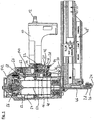
- the pneumatic nailer has a handle 10, at the rear end of a central compressed air port 12 is arranged.
- the handle 10 is located on a lower housing part 140, which is closed at the top by a housing cap 142.
- the manually operable trigger 14 is pivotally mounted about a pivot axis 16 on the housing of the pneumatic nailer and arranged so that it from a User holding the pneumatic nailer on the handle 10 can be conveniently operated with the index finger.
- a button 18 located at the top of the trigger 14 engages a switching pin 20 of a second control valve 22, displaces the switching pin 20 upwardly and thereby controls the second control valve 22. Since this activation of the second control valve 22 is effected directly by the button 18 fixedly arranged on the trigger 14, it takes place independently of the actuation of a touch sensor 24.
- the attachment probe 24 projects downwards over the mouth 26 of a necking tool 28 by a few millimeters. If the pneumatic nailer is attached to a workpiece, the touch sensor 24 is displaced upward against the force of a spring, not shown, until it is flush with the mouth 26.
- the Aufsetzmlers 24 is mechanically coupled to a power transmission element 30 which moves with the movement of the Aufsetzmlers 24 upwards.
- the power transmission element 30 is movably guided on the housing of the pneumatic nailer and has a slot 32 through which the pivot axis 16 of the trigger 14 is passed.
- the force transmission element 30 moves from the initial position drawn upwards and takes with a fixed to the power transmission element 30 stop pin 34, the free end of a lever 36, the fixed end pivotally inside the trigger 14 and near the free End hinged.
- the lever 36 is then arranged approximately parallel to the longitudinal direction of the trigger 14 and its upper side acts as a button 40, the joint operation of the Aufsetzrs 24 and the trigger 14 displaces a switching pin 42 of a first control valve 44 upwards and thus activates the first control valve 44.
- the mouth tool 28 has a receptacle 46, to which a fastening means is supplied from a magazine 48 in each case. From this position within the receptacle 46, the fastening means - for example, a nail, a pin or a clip - driven by a driving ram 50 which is connected to a working piston 52 of the pneumatic nailer.
- the working piston 52 is guided in a working cylinder 54.
- Above the working cylinder 54 and this sealingly closing a main valve 56 is arranged, to the right thereof a pilot valve 58 and to the right again a throttle 60 and a chamber 62. Details of these elements and the function of the device are based on the detail enlargements FIGS. 2 to 4 explained in more detail.
- the housing of the pneumatic nailer has a housing interior 64 which is ventilated in the initial state of the pneumatic nailer, that is connected to the compressed air connection 12 and standing under operating pressure.
- a second control line 68 is connected via an annular gap 70 with radial bores 72 of the second control valve 22.
- an upper O-ring 74 of the second control valve 22 seals the control pin 20 relative to the sleeve 66, so that a connection to a conduit 78 which is connected to the housing interior 64 is shut off.
- a lower O-ring 76 of the second control valve 22 is not in seal, so that the radial bores 72 and thus the second control line 68 are connected via the annular gap between the switching pin 20 and the sleeve 66 with outside air.
- the second control line 68 is thus vented.
- the switch pin 20 is displaced upwardly by the button 18 so that the upper O-ring 74 moves out of the seal and the lower O-ring 76 seals the switch pin 20 against the sleeve 66.
- the connection of the second control line 68 is shut off with the outside air.
- the second control line 68 is connected via the radial bores 72 with the conduit 78 and thus ventilated.
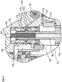
- the switching pin 42 of the first control valve 44 is also guided in a sleeve 80 inserted into the housing and sealed with respect thereto. Upon a joint actuation of the trigger 14 and the Aufsetzmans 24, the switching pin 42 of the first control valve 44 is actuated via the lever 36. In the non-actuated state of the first control valve 42 shown, a first control line 82 is used to control the pilot control valve 58 (more on this in connection with FIGS Figures 3 and 4 ), vented, via an obliquely arranged bore 90 in the housing of the pneumatic nailer and two radial bores 86 in the sleeve 80 of the first control valve 44.
- the radial bores 86 are connected via an annular gap between the sleeve 80 and the switching pin 42 of the first control valve 44 with outside air connected as long as the lower O-ring 88 of the first control valve 44 is not in seal, corresponding to the initial state as in FIG. 2 shown.
- an upper O-ring 90 which is disposed above the radial bores 86, in sealing and thus blocks a connection via a line 92 to the housing interior 64 from.
- the lower O-ring 88 Upon actuation of the first control valve 44, the lower O-ring 88 succeeded in sealing and blocks the connection of the first control line 42 to the outside air. At the same time, the upper O-ring 90 moves out of the seal, so that the first control line 82 is connected via the obliquely arranged bore 84, the radial bores 86 and the line 92 to the ventilated housing interior 64.
- the pilot valve 58 is best in the FIG. 3 recognizable. It has a control piston 94, which is guided in a guide sleeve 96. The lower end of the control piston 94 is guided in an integral with the housing intermediate sleeve 98 and sealed with respect to this with an O-ring 100. In the initial state of the pneumatic nailer, so with vented first control line 82, the control piston 94 is in the lower position shown. In this position, it is held by the force of a spring 102.
- the spool 94 has a middle O-ring 104 and an upper O-ring 106 in addition to the lower O-ring 100.
- the upper O-ring 106 seals the control piston from the guide sleeve 96 thereby closing a connection to the vent opening 108 connected to outside air.
- the middle O-ring 104 is not in the seal, so that a main control line 110 is connected via radial bores 112 in the guide sleeve 96 and the annular gap between the control piston 94 and guide sleeve 96 on the middle O-ring 104 with the vented housing interior 64.
- the main control line 110 is connected to a space 114 above an actuator 116 of the main valve 56, so that the actuator 116 is acted upon by a downward force and thereby seals the upper edge of the working cylinder 54 by means of a further O-ring 118 relative to the housing interior 64.
- the actuator 116 is acted upon by a spring 120 with a force in the direction of this, the working cylinder 54 occluding position.
- FIG. 3 on the right of the control piston 94 a locking piston 124 guided horizontally in a bore of the housing cap 142 is shown. He is drawn, according to the initial state of the pneumatic nailer, in a rest position in which he is in the FIG. 3 right. In this rest position is an end 126 of the locking piston 124 at a distance from the control piston 94 and does not collide in the case of ventilation of the first control line 82 with the upward movement of the control piston 94th
- the locking piston 124 is hollow and its interior forms together with the in the FIG. 3 To the right of the O-ring 126 of the locking piston 124 located annular gap around the locking piston 124 around the chamber 62.
- a spring 128 is arranged, which is the locking piston 124 with a force in its blocking position, which is shifted from the drawn rest position to the left, acted upon.
- the end 126 of the locking piston 124 is in the path of a diameter-expanded, lower portion 130 of the control piston 94 into it, so that a displacement of the triggering a Eintreibvorgangs up to moving control piston 94 is prevented.
- the coming from the second control valve 22 second control line 68 is connected via a throttle 60 and an oblique bore 132 with the chamber 62. Therefore, venting the second control line 68 as a result of actuation of the second control valve 22 results in slow ventilation of the chamber 62 via the throttle 60. If the pressure in the chamber 62 exceeds a predetermined pressure threshold, the pressure applied by the spring 128 and pressure in FIG the chamber 62 on the locking piston 124 in the direction towards its locking position towards exerted forces greater than that on the left surface of the locking piston 124 by the pressure in the housing interior 64 to the right, d. H. in the direction of its rest position, forces exerted, and the locking piston 124 moves in its blocking position. As a result, the triggering of a driving operation is prevented when the pressure in the chamber 62 exceeds the predetermined pressure threshold.
- the obliquely arranged bore 132 which is vented via the throttle 60, on one side of the throttle 60 leads to the chamber 62 and continues on the other side to a radial bore 134 in the guide sleeve 96 of the pilot valve 58th
- This radial bore 134 is connected to an internal pierce 136 in the inner bore of the guide sleeve 96.
- the internal pierce 136 is located between the upper O-ring 106 and the middle O-ring 104 of the control piston 94.
- an O-ring 138 In the internal pierce 136 is an O-ring 138 arranged, the one Forms check valve, which seals the radial bore 134 relative to the annular gap between the control piston 94 and guide sleeve 96.
- the middle O-ring 104 is not in seal, so that the control chamber 144 forming an annular gap is connected to the housing interior 64 and is under compressed air.
- the pressure in the radial bore 134 corresponds to the pressure within the chamber 62, so that the O-ring 138 is pressed into the internal piercing 136 and the radial bore 134 closes.
Landscapes
- Engineering & Computer Science (AREA)
- Mechanical Engineering (AREA)
- Physics & Mathematics (AREA)
- Fluid Mechanics (AREA)
- Portable Nailing Machines And Staplers (AREA)
Description
Die Erfindung betrifft einen Druckluftnagler mit einem Arbeitskolben, der mit einem Eintreibstößel zum Eintreiben eines Befestigungsmittels verbunden ist und beim Auslösen eines Eintreibvorgangs mit Druckluft beaufschlagt wird, und einer Auslöseeinrichtung, die einen handbetätigbaren Auslöser und einen Aufsetzfühler aufweist, wobei eine gemeinsame Betätigung von Auslöser und Aufsetzfühler ein erstes Steuerventil ansteuert und einen Eintreibvorgang auslösen kann. Ein solcher Druckluftnagler ist aus
Derartige Druckluftnager sind aus dem Stand der Technik bekannt. Bei dem Aufsetzfühler handelt es sich um ein mechanisches Bauteil, das von einer Feder in einer über ein Mündungswerkzeug des Druckluftnaglers überstehenden Position gehalten wird. Wird der Druckluftnager an ein Werkstück angesetzt, wird der Aufsetzfühler gegen die Kraft der Feder verlagert, bis das Mündungswerkzeug an dem Werkstück anliegt. Nur bei derart betätigtem Aufsetzfühler kann ein Eintreibvorgang ausgelöst werden. Dadurch bieten die bekannten Druckluftnagler gegenüber Geräten ohne Aufsetzfühler eine erheblich verbesserte Sicherheit gegen unbeabsichtigte Auslösungen.Such Druckluftnager are known from the prior art. The touch sensor is a mechanical component which is held by a spring in a position overhanging a nozzle tool of the pneumatic nailer. If the air rod is attached to a workpiece, the touch sensor is displaced against the force of the spring until the muzzle tool rests against the workpiece. Only with such actuated Aufsetzfühler a driving operation can be triggered. As a result, the known compressed air nailers offer a significantly improved security against unintentional release compared to devices without Aufsetzfühler.
Druckluftnagler mit einer Auslöseeinrichtung der beschriebenen Art können in zwei unterschiedlichen Betriebsarten eingesetzt werden. Bei der sogenannten Einzelauslösung wird der Druckluftnagler zunächst an ein Werkstück angesetzt und dadurch der Aufsetzfühler betätigt. Nachfolgend wird von Hand der Auslöser betätigt und dadurch ein einzelner Eintreibvorgang ausgelöst.Pneumatic nailer with a triggering device of the type described can be used in two different modes. In the so-called single release the pneumatic nailer is first attached to a workpiece and thereby actuated the landing sensor. Subsequently, the trigger is actuated by hand, thereby triggering a single drive.
Bei der sogenannten Kontaktauslösung, auch als "Touchen" bezeichnet, hält der Benutzer den Auslöser bereits gedrückt, während er den Druckluftnagler an das Werkstück ansetzt. Beim Ansetzen an das Werkstück wird der Aufsetzfühler betätigt und dadurch ein Eintreibvorgang auslöst. Der Druckluftnagler kann wiederholt in schneller Folge angesetzt werden, was ein sehr schnelles Arbeiten ermöglicht, insbesondere wenn für eine ausreichende Befestigung viele Befestigungsmittel eingetrieben werden müssen, an deren Positioniergenauigkeit nur geringe Anforderungen gestellt werden.In the so-called contact release, also referred to as touch, the user already holds the trigger while pressing the pneumatic nailer against the workpiece. When attaching to the workpiece of the touch sensor is actuated, thereby initiating a drive-in. The pneumatic nailer can be repeated in rapid sequence can be recognized, which allows a very fast working, especially if many fasteners must be driven for a sufficient attachment to the positioning accuracy only small demands are made.
In bestimmten Situationen geht von dem Kontaktauslöseverfahren jedoch ein erhöhtes Verletzungsrisiko aus. Hält der Benutzer den handbetätigten Auslöser beispielsweise nicht nur dann gedrückt, wenn er den Druckluftnaglers auf ein und demselben Werkstück in einem Abstand von einigen Zentimetern vom zuletzt eingetriebenen Befestigungsmittel aufsetzen will, sondern auch dann, wenn er zu einem anderen, möglicherweise entfernt angeordnetem Werkstück wechselt, kann bei einer unbeabsichtigten Berührung eines Gegenstands oder Körperteils mit dem Aufsetzfühler ein Eintreibvorgang ausgelöst werden. Beispielsweise kann es zu Unfällen kommen, wenn ein Benutzer (unter Missachtung wichtiger Sicherheitsvorschriften) mit dem Druckluftnagler auf eine Leiter steigt, dabei den Auslöser gedrückt hält und versehentlich mit dem Aufsetzfühler sein Bein streift.In certain situations, however, the contact triggering procedure entails an increased risk of injury. For example, if the user wishes to hold the manual trigger not only to place the pneumatic nailer on one and the same workpiece a few centimeters away from the last driven fastener, but also to move to another, possibly remotely located, workpiece, can be triggered in an accidental contact of an object or body part with the Aufsetzfühler a driving operation. For example, accidents can occur when a user (in disregard of important safety regulations) climbs a ladder with the pneumatic nailer while holding the trigger and accidentally brushing his leg with the touch probe.
Davon ausgehend ist es die Aufgabe der Erfindung, einen Druckluftnagler der eingangs genannten Art so zu verbessern, dass er weiterhin im Kontaktauslöseverfahren verwendet werden kann, jedoch eine größere Sicherheit gegen unbeabsichtigte Auslösungen bietet.On this basis, it is the object of the invention to improve a pneumatic nailer of the type mentioned so that it can continue to be used in the contact triggering process, but offers greater security against accidental tripping.
Diese Aufgabe wird gelöst durch den Druckluftnagler mit den Merkmalen des Anspruchs 1. Vorteilhafte Ausgestaltungen sind in den sich anschließenden Unteransprüchen angegeben.This object is achieved by the pneumatic nailer with the features of
Der Druckluftnagler hat
- einen Arbeitskolben, der mit einem Eintreibstößel zum Eintreiben eines Befestigungsmittels verbunden ist und beim Auslösen eines Eintreibvorgangs mit Druckluft beaufschlagt wird,
- eine Auslöseeinrichtung, die einen handbetätigbaren Auslöser und einen Aufsetzfühler aufweist, wobei eine gemeinsame Betätigung von Auslöser und Aufsetzfühler ein erstes Steuerventil ansteuert und einen Eintreibvorgang auslösen kann,
- ein zweites Steuerventil, das bei einer Betätigung des Auslösers unabhängig von einer Betätigung des Aufsetzfühlers angesteuert wird,
- eine Kammer, die über eine Drossel bei Ansteuerung des zweiten Steuerventils entweder belüftet oder entlüftet wird, und
- einen Sperrkolben, der von einer Ruhestellung in eine Sperrstellung verlagert wird, wenn der Druck der Kammer eine vorgegebene Druckschwelle passiert und der in der Sperrstellung das Auslösen eines Eintreibvorgangs verhindert.
- a working piston, which is connected to a driving ram for driving in a fastening means and is subjected to the triggering of a driving operation with compressed air,
- a triggering device having a hand-operated trigger and a touchdown sensor, wherein a common actuation of the trigger and Aufsetzfühler controls a first control valve and can trigger a drive-in,
- a second control valve, which is actuated upon actuation of the trigger independently of an actuation of the Aufsetzfühlers,
- a chamber which is either vented or vented via a throttle in the control of the second control valve, and
- a blocking piston, which is displaced from a rest position to a blocking position when the pressure of the chamber passes a predetermined pressure threshold and prevents the triggering of a driving operation in the blocking position.
Der Druckluftnager wird zum Eintreiben von Befestigungsmitteln wie Nägeln, Stiften oder Klammern verwendet. Hierzu kann der Druckluftnagler ein Magazin für die Befestigungsmittel aufweisen, aus dem jeweils ein Befestigungsmittel einer Aufnahme eines Mündungswerkzeugs des Druckluftnaglers zugeführt wird.The pneumatic rodger is used to drive fasteners such as nails, pins or staples. For this purpose, the pneumatic nailer can have a magazine for the fastening means, from which in each case a fastening means is supplied to a receptacle of a necking tool of the pneumatic nailer.
Sowohl der Antrieb als auch die Steuerung des Druckluftnaglers können vollständig pneumatisch erfolgen, eine Versorgung mit elektrischer Energie ist daher nicht erforderlich.Both the drive and the control of the pneumatic nailer can be done completely pneumatically, a supply of electrical energy is therefore not required.
Beim Auslösen eines Eintreibvorgangs wird ein Arbeitskolben des Druckluftnaglers mit Druckluft beaufschlagt. Dabei treibt der Arbeitskolben einen Eintreibstößel an, der mit dem Arbeitskolben verbunden ist. Der Eintreibstößel trifft auf ein hinteres Ende des Befestigungsmittels in der Aufnahme des Mündungswerkzeugs auf und treibt das Befestigungsmittel in das Werkstück ein.When initiating a driving operation, a working piston of the pneumatic nailer is pressurized with compressed air. In this case, the working piston drives a Eintreibstößel, which is connected to the working piston. The tappet meets a rear one End of the fastener in the receptacle of the muzzle tool and drives the fastener into the workpiece.
Die Auslöseeinrichtung hat einen handbetätigbaren Auslöser, beispielsweise in Form eines Kipp- oder Schiebetasters, und einen Aufsetzfühler. Bei dem Aufsetzfühler kann es sich um ein mechanisches Bauelement handeln, das über das vordere Ende des Mündungswerkzeugs übersteht und von einer Feder in dieser Stellung gehalten wird, bis der Druckluftnagler an ein Werkstück angesetzt wird. Dann wird der Aufsetzfiihler entgegen der Richtung der Federkraft und entgegen der Eintreibrichtung verlagert. Erfolgt diese Betätigung des Aufsetzfühlers gemeinsam mit einer Betätigung des Auslösers, wird ein erstes Steuerventil angesteuert, wodurch ein Eintreibvorgang ausgelöst werden kann.The triggering device has a hand-operated trigger, for example in the form of a tilt or push button, and a touch sensor. The touch sensor may be a mechanical component that projects beyond the front end of the muzzle tool and is held in this position by a spring until the pneumatic nailer is attached to a workpiece. Then the Aufsetzfiihler is displaced against the direction of the spring force and against the driving direction. If this actuation of the touch probe together with an actuation of the trigger, a first control valve is actuated, whereby a driving operation can be triggered.
Bei einer gemeinsamen Betätigung von Auslöser und Aufsetzfühler wird das erste Steuerventil angesteuert. Wird nur entweder der handbetätigbare Auslöser oder der Aufsetzfühler betätigt, wird das erste Steuerventil nicht angesteuert. Für eine gemeinsame Betätigung von Auslöser und Aufsetzfühler reicht es aus, wenn sowohl der Auslöser als auch der Aufsetzfühler zu einem bestimmten Zeitpunkt beide zugleich im betätigten Zustand sind. Dies kann einerseits durch eine gleichzeitige Betätigung erreicht werden, aber auch in einer beliebigen Reihenfolge. Beispielsweise kann, wie es für eine Einzelauslösung typisch ist, zunächst der Aufsetzfühler betätigt werden und anschließend der handbetätigbare Auslöser. Im Kontaktaüslösebetrieb kann hingegen zuerst der handbetätigbare Auslöser und dann der Aufsetzfühler betätigt werden.With a common actuation of trigger and Aufsetzfühler the first control valve is activated. If only one of the manually actuable release and the touch sensor is actuated, the first control valve will not be actuated. For a joint actuation of trigger and Aufsetzfühler it is sufficient if both the trigger and the touch sensor at a certain time both at the same time in the actuated state. This can be achieved on the one hand by a simultaneous operation, but also in any order. For example, as is typical for a single trigger, first the touchdown sensor can be actuated and then the manually operated trigger. In Kontaktaüslösebetrieb, however, the hand-actuated trigger and then the touch sensor can be operated first.
Die Ansteuerung des ersten Steuerventils kann durch eine mechanische Kopplung des handbetätigbaren Auslösers und des Aufsetzfühlers erreicht werden. Beispielsweise kann ein Steuerstift des ersten Steuerventils erst bei einer gemeinsamen Betätigung von Auslöser und Aufsetzfühler verlagert und das erste Steuerventil dadurch angesteuert werden.The control of the first control valve can be achieved by a mechanical coupling of the manually operated release and the Aufsetzfühlers. For example, a control pin of the first control valve only at a common Actuation of trigger and Aufsetzfühler shifts and the first control valve thereby controlled.
Die Ansteuerung des ersten Steuerventils kann einen Eintreibvorgang auslösen. Dies geschieht bei der Erfindung, wenn sich der Sperrkolben in seiner Ruhestellung befindet. Befindet sich der Sperrkolben hingegen in seiner Sperrstellung, wird das Auslösen eines Eintreibvorgangs bei einer Ansteuerung des ersten Steuerventils verhindert.The activation of the first control valve can trigger a drive-in process. This is done in the invention, when the locking piston is in its rest position. On the other hand, when the blocking piston is in its blocking position, the triggering of a driving-in process is prevented when the first control valve is activated.
Bei der Erfindung wird ein zweites Steuerventil bei einer Betätigung des handbetätigbaren Auslösers unabhängig von einer Betätigung des Aufsetzfühlers angesteuert. Das zweite Steuerventil wird also bei jeder Betätigung des Auslösers angesteuert. Hierzu kann beispielsweise ein Steuerstift des zweiten Steuerventils so angeordnet sein, dass er bei jeder Betätigung des Auslösers aus seiner Ruhestellung verlagert wird.In the invention, a second control valve is actuated upon actuation of the manually actuable trigger independently of an actuation of the Aufsetzfühlers. The second control valve is thus activated with each actuation of the trigger. For this purpose, for example, a control pin of the second control valve may be arranged so that it is displaced from its rest position with each actuation of the trigger.
Bei einer solchen Ansteuerung des zweiten Steuerventils wird eine Kammer über eine Drossel belüftet oder entlüftet. Mit "Belüften" ist stets gemeint, dass eine Verbindung zu einem Druckluft führenden Raum hergestellt wird. Mit "Entlüften" ist stets gemeint, dass eine Verbindung zu einem drucklosen Raum, insbesondere zur Außenluft, hergestellt wird.In such a control of the second control valve, a chamber is vented via a throttle or vented. By "venting" is always meant that a connection is made to a compressed air leading room. By "venting" is always meant that a connection to a non-pressurized space, in particular to the outside air, is produced.
Ob bei der Erfindung bei Ansteuerung des zweiten Steuerventils eine Belüftung oder eine Entlüftung der Kammer erfolgt, hängt von der Bauart des Druckluftnaglers ab: Bei einem Druckluftnagler, dessen Kammer bei Ansteuerung des zweiten Steuerventils belüftet wird, weist der Druckluftnagler eine Leitung auf, die die Kammer mit einem Druckluft führenden Raum verbindet. Bei einem Druckluftnagler, dessen Kammer bei Ansteuerung des zweiten Steuerventils entlüftet wird, weist der Druckluftnagler eine Leitung auf, die die Kammer mit einem drucklosen Raum, insbesondere mit Außenluft, verbindet. In beiden Fällen können sich die Drossel und das zweite Steuerventil in der jeweiligen Leitung befinden. Soll die Kammer belüftet werden, ist die Kammer in einem Ausgangszustand des Druckluftnaglers drucklos. Bei Ansteuerung des zweiten Steuerventils strömt dann Luft über die Drossel zu, sodass sich der Druck in der Kammer erhöht. Soll die Kammer entlüftet werden, steht sie in einem Ausgangszustand des Druckluftnaglers unter erhöhtem Druck. Bei Ansteuerung des zweiten Steuerventils strömt die in der Kammer befindliche Luft langsam über die Drossel ab, sodass der Druck in der Kammer sinkt.Whether in the invention when controlling the second control valve, ventilation or venting of the chamber takes place, depends on the design of the pneumatic nailer: In a pneumatic nailer, the chamber is vented upon actuation of the second control valve, the pneumatic nailer on a line which the chamber connects with a compressed air leading room. In a pneumatic nailer, the chamber is vented when driving the second control valve, has the Pneumatic nailer on a line that connects the chamber with a non-pressurized space, especially with outside air. In both cases, the throttle and the second control valve may be located in the respective line. If the chamber is to be ventilated, the chamber is depressurized in an initial state of the pneumatic nailer. When the second control valve is actuated, air then flows via the throttle, so that the pressure in the chamber increases. If the chamber is to be vented, it is in an initial state of the pneumatic nailer under increased pressure. When the second control valve is actuated, the air in the chamber flows slowly through the throttle, so that the pressure in the chamber drops.
In beiden Fällen passiert der Druck in der Kammer nach einer gewissen Zeit eine vorgegebene Druckschwelle. Bei einer durch Ansteuerung des zweiten Steuerventils belüfteten Kammer übersteigt der Druck die Druckschwelle. Bei einer bei Ansteuerung des zweiten Steuerventils entlüfteten Kammer sinkt der Druck unter die vorgegebene Drückschwelle. In beiden Fälle führt das Passieren der vorgegebenen Druckschwelle dazu, dass der Sperrkolben von einer Ruhestellung in eine Sperrstellung verlagert wird. In der Sperrstellung wird das Auslösen eines Eintreibvorgangs verhindert.In both cases, the pressure in the chamber after a certain time passes a predetermined pressure threshold. In a ventilated by driving the second control valve chamber, the pressure exceeds the pressure threshold. When a chamber is vented when the second control valve is actuated, the pressure drops below the predetermined pressure threshold. In both cases, passing the predetermined pressure threshold causes the blocking piston to be displaced from a rest position to a blocking position. In the blocking position the triggering of a drive-in process is prevented.
Daher kann bei der Erfindung ein Eintreibvorgang nach dem Betätigen des Auslösers nur so lange ausgelöst werden, wie der Druck in der Kammer die vorgegebene Druckschwelle noch nicht passiert hat. Wird der Auslöser also für einen längeren Zeitraum betätigt und hat der Druck in der Kammer infolgedessen die Druckschwelle passiert, kommt es durch Betätigen des Aufsetzfühlers nicht zur Auslösung eines Eintreibvorgangs, weil dies durch den sich dann in der Sperrstellung befindlichen Sperrkolben verhindert wird. Es wird also verhindert, dass durch eine erst lange nach der Betätigung des Auslösers erfolgende Betätigung des Aufsetzfühlers ein Eintreibvorgang ausgelöst wird. Dadurch können die meisten unbeabsichtigten Auslösungen, bei denen der Benutzer den Auslöser aus Unachtsamkeit länger als nötig betätigt hat, zuverlässig verhindert werden.Therefore, in the invention, a driving operation after actuation of the trigger can be triggered only as long as the pressure in the chamber has not yet passed the predetermined pressure threshold. If the trigger is thus actuated for a longer period of time and the pressure in the chamber has consequently passed the pressure threshold, actuation of the attachment sensor does not trigger a driving operation, because this is prevented by the blocking piston which is then in the blocking position. It is thus prevented that a driving operation is triggered by a long after the actuation of the trigger taking place actuation of the touch sensor. This allows most unintentional Trips where the user has accidentally pressed the release button longer than necessary can be reliably prevented.
In einer Ausgestaltung wird die Kammer bei nicht betätigtem Auslöser entlüftet bzw. belüftet. Weist der Druckluftnagler eine Kammer auf, die bei Ansteuerung des zweiten Steuerventils belüftet wird, wird die Kammer bei nicht betätigtem Auslöser entlüftet. Weist der Druckluftnagler eine Kammer auf, die bei Ansteuerung des zweiten Steuerventils entlüftet wird, wird die Kammer bei nicht betätigtem Auslöser belüftet. Die Entlüftung bzw. Belüftung der Kammer bei nicht betätigtem Auslöser kann über das zweite Steuerventil erfolgen, gegebenenfalls auch über das zweite Steuerventil und die Drossel. In diesem Fall kann die bei Ansteuerung des zweiten Steuerventils zum Belüften bzw. Entlüften der Kammer verwendete Leitung, in der auch die Drossel angeordnet ist, auch für das Entlüften bzw. Belüften der Kammer bei nicht betätigtem Auslöser genutzt werden.In one embodiment, the chamber is vented or vented when not actuated trigger. If the pneumatic nailer has a chamber which is vented when the second control valve is actuated, the chamber is vented when the trigger is not actuated. If the pneumatic nailer has a chamber which is vented when the second control valve is actuated, the chamber is ventilated when the trigger is not actuated. The venting or ventilation of the chamber when not actuated trigger can be done via the second control valve, possibly also via the second control valve and the throttle. In this case, the line used in the control of the second control valve for venting or venting the chamber, in which the throttle is arranged, also be used for venting or venting the chamber when not actuated trigger.
In jedem Fall führt die genannte Ausgestaltung dazu, dass sich in der Kammer bei nicht betätigtem Auslöser der gewünschte, einem Ausgangszustand des Druckluftnaglers entsprechende Druck einstellt. Dadurch befindet sich der Druckluftnagler bei nicht betätigtem Auslöser jedenfalls nach einer gewissen Zeit stets in seinem Ausgangszustand. Befindet sich auch die Drossel in der für das Entlüften bzw. Belüften der Kammer bei nicht betätigtem Auslöser verwendeten Leitung, wird dieser Ausgangszustand erst nach einer gewissen Zeit wieder erreicht, falls zuvor der Druck in der Kammer die vorgegebene Druckschwelle passiert hatte. Hatte ein Benutzer also zuvor den Auslöser für eine längere Zeit betätigt, sodass die Druckschwelle passiert wurde, kann ein weiterer Eintreibvorgang durch des Betätigen des Aufsetzfühlers erst dann erfolgen, wenn der Auslöser für eine gewisse Zeit unbetätigt geblieben ist. Bis dahin ist der Druckluftnagler gesperrt. Wird dieser gesperrte Zustand von einem Benutzer als lästig empfunden, kann dies in Zukunft einer unbedachten Dauerbetätigung des Auslösers entgegenwirken und somit die Anwendungssicherheit des Druckluftnaglers weiter verbessern.In any case, the above-mentioned embodiment means that the desired pressure, which corresponds to an initial state of the pneumatic nailer, is established in the chamber when the trigger is not actuated. As a result, the compressed air nailer is always in its initial state after a certain time when the trigger is not actuated. If the throttle is also in the line used for venting or venting the chamber when the trigger is not actuated, this initial state is only reached again after a certain time, if the pressure in the chamber had previously passed the predetermined pressure threshold. Thus, if a user had previously pressed the trigger for a long time, so that the pressure threshold was passed, a further driving operation by pressing the Aufsetzfühlers can only be done when the trigger has remained unactuated for a certain time. Until then, the pneumatic nailer is locked. If this locked state is perceived as annoying by a user, this can happen in the future counteract a careless continuous operation of the trigger and thus further improve the safety of the application of the pneumatic nailer.
In einer Ausgestaltung ist ein Öffnungsquerschnitt der Drossel so bemessen, dass bei Betrieb des Druckluftnaglers mit einem dafür vorgesehenen Betriebsdruck der Druck in der Kammer die vorgegebene Druckschwelle in einem Zeitraum von 0,1 s bis 10s nach Ansteuerung des zweiten Steuerventils passiert. Insbesondere kann die Druckschwelle in einem Zeitraum zwischen 1 s und 5 s nach Ansteuerung des zweiten Steuerventils passiert werden, zum Beispiel nach ungefähr 4 s. Der Öffnungsquerschnitt der Drossel kann einstellbar sein, sodass der Zeitraum individuell reguliert werden kann. Bevorzugt erfolgt diese Regulierung nur einmalig durch den Hersteller des Druckluftnaglers und ist nur durch unzulässige Manipulation durch einen Anwender veränderbar. In jedem Fall wird der Druckluftnagler rechtzeitig gesperrt, um in vielen typischen Anwendungssituationen einen Eintreibvorgang in Folge einer unbeabsichtigten Betätigung des Aufsetzfühlers zu verhindern.In one embodiment, an opening cross section of the throttle is dimensioned such that during operation of the pneumatic nailer with a designated operating pressure, the pressure in the chamber, the predetermined pressure threshold in a period of 0.1 s to 10 s after activation of the second control valve happens. In particular, the pressure threshold can be passed in a period between 1 s and 5 s after activation of the second control valve, for example after approximately 4 s. The opening cross-section of the throttle can be adjustable, so that the period can be individually regulated. Preferably, this regulation takes place only once by the manufacturer of the pneumatic nailer and can only be changed by impermissible manipulation by a user. In any case, the pneumatic nailer is locked in time to prevent in many typical application situations a driving operation as a result of unintentional actuation of the Aufsetzfühlers.
In einer Ausgestaltung weist der Druckluftnagler ein Ventil auf, über das die Kammer beim Auslösen eines Eintreibvorgangs entlüftet bzw. belüftet wird. Wird die Kammer bei Ansteuerung des zweiten Steuerventils belüftet, soll sie beim Auslösen eines Eintreibvorgangs entlüftet werden. Wird die Kammer bei Ansteuerung des zweiten Steuerventils entlüftet, soll sie beim Auslösen eines Eintreibvorgangs belüftet werden. Dadurch wird beim Auslösen eines Eintreibvorgangs hinsichtlich des Drucks in der Kammer der Ausgangszustand wieder hergestellt. Dies kann sehr schnell geschehen. Wird nach dem Eintreibvorgang der Auslöser weiterhin gedrückt gehalten, nähert sich der Druck in der Kammer in der eingangs geschilderten Weise wieder der Druckschwelle, welche nach dem vorgegebenen Zeitraum passiert wird. Bis dahin ist jederzeit eine weitere Auslösung durch Betätigen des Aufsetzfühlers möglich, sodass der Druckluftnagler ohne Beschränkung für schnell aufeinanderfolgende Eintreibvorgängen im Kontaktauslöseverfahren geeignet ist.In one embodiment, the pneumatic nailer has a valve through which the chamber is vented or vented when triggering a Eintreibvorgangs. If the chamber is vented when controlling the second control valve, it should be vented when a Eintreibvorgangs. If the chamber is vented when the second control valve is actuated, it should be ventilated when a drive-in process is triggered. As a result, the initial state is restored upon initiation of a driving operation with respect to the pressure in the chamber. This can happen very fast. If, after the drive-in operation, the trigger is still kept pressed, the pressure in the chamber approaches in the manner described at the beginning again the pressure threshold, which is passed after the predetermined period of time. Until then, at any time, another trip through Actuation of the touch probe is possible, so that the pneumatic nailer is suitable without restriction for fast successive driving operations in the contact triggering method.
In einer Ausgestaltung wird beim Auslösen eines Eintreibvorgangs ein Steuerraum infolge der Ansteuerung des ersten Steuerventils entlüftet bzw. belüftet, wobei das Ventil ein Rückschlagventil ist, das die Kammer mit dem Steuerraum verbindet. Der Steuerraum kann sich insbesondere in oder an einem Vorsteuerventil befinden, mit dem ein Hauptventil, das für die Belüftung des Arbeitszylinders zuständig ist, angesteuert wird. Es kann sich auch um einen Steuerraum im oder am Hauptventil handeln. Um einen Eintreibvorgang auszulösen, muss der Druck in dem Steuerraum verändert werden. Dies geschieht durch Entlüften bzw. Belüften infolge der Ansteuerung des ersten Steuerventils. Bei dieser Ausgestaltung ist das Ventil, das für das Wiederherstellen des Ausgangszustands in der Kammer beim Auslösen eines Eintreibvorgangs zuständig ist, ein Rückschlagventil, das die Kammer mit dem Steuerraum verbindet. Entspricht der Druck in dem Steuerraum einem Ausgangszustand des Druckluftnaglers, ist das Rückschlagventil geschlossen, sodass sich der Druck in der Kammer bei Betätigung des zweiten Steuerventils in der gewünschten Weise der Druckschwelle nähert. Wird ein Eintreibvorgang ausgelöst, ändert sich der Druck in dem Steuerraum, das Rückschlagventil öffnet und der Druck in der Kammer nimmt wieder den Ausgangszustand an.In one embodiment, when a drive-in operation is triggered, a control chamber is vented or vented as a result of the actuation of the first control valve, the valve being a check valve which connects the chamber to the control chamber. The control chamber may in particular be located in or on a pilot valve, with which a main valve, which is responsible for the ventilation of the working cylinder, is controlled. It can also be a control room in or on the main valve. To trigger a drive-in process, the pressure in the control room must be changed. This is done by venting or venting as a result of the control of the first control valve. In this embodiment, the valve which is responsible for restoring the initial state in the chamber upon initiation of a drive-in operation is a check valve which connects the chamber to the control chamber. If the pressure in the control chamber corresponds to an initial state of the pneumatic nailer, the check valve is closed so that the pressure in the chamber approaches the pressure threshold in the desired manner when the second control valve is actuated. When a drive-in process is triggered, the pressure in the control chamber changes, the check valve opens and the pressure in the chamber returns to the initial state.
In einer Ausgestaltung weist das Rückschlagventil einen O-Ring auf, der in einem Inneneinstich einer Hülse angeordnet und eine von dem Inneneinstich zu einer Außenseite der Hülse führende Bohrung verschließt. Die Hülse kann beispielsweise eine Führungshülse für einen Steuerkolben eines Vorsteuerventils sein. Die genannte Ausgestaltung des Rückschlagventils ermöglicht einen besonders kompakten Aufbau.In one embodiment, the check valve has an O-ring, which is arranged in an internal piercing of a sleeve and closes a bore leading from the internal pierce to an outer side of the sleeve. The sleeve may for example be a guide sleeve for a control piston of a pilot valve. The aforementioned embodiment of the check valve allows a particularly compact design.
In einer Ausgestaltung schaltet der Sperrkolben in der Sperrstellung den Druckluftnagler vollständig drucklos. Hierzu kann der Sperrkolben so angeordnet sein, dass er eines oder mehrere weitere Ventile ansteuert, mit denen ein zentraler Druckluftanschluss des Geräts abgesperrt und der Innenraum des Druckluftnaglers komplett entlüftet wird. Diese Lösung ist konstruktiv relativ aufwendig, verhindert jedoch zuverlässig, dass ein weiterer Eintreibvorgang ausgelöst werden kann. Außerdem bleibt insbesondere die vollständige Entlüftung des Druckluftnaglers nicht unbemerkt, sodass der Benutzer auf die aus Sicherheitsgründen nicht optimale Dauerbetätigung des Auslösers aufmerksam gemacht wird.In one embodiment, the blocking piston switches the compressed air nailer completely depressurized in the blocking position. For this purpose, the blocking piston can be arranged so that it controls one or more further valves with which a central compressed air connection of the device is shut off and the interior of the pneumatic nailer is completely vented. This solution is structurally relatively expensive, but reliably prevents that another driving operation can be triggered. In addition, in particular, the complete ventilation of the pneumatic nailer does not go unnoticed, so that the user is made aware of the security reasons not optimal continuous operation of the shutter.
In einer Ausgestaltung verschließt der Sperrkolben in der Sperrstellung eine Entlüftungsöffnung, über die ein Steuerraum beim Auslösen eines Eintreibvorgangs entlüftet wird. Die für das Auslösen des Eintreibvorgangs notwendige Entlüftung des Steuerraums kann daher nicht erfolgen. Auch auf diese Weise kann eine unbeabsichtigte Auslösung zuverlässig verhindert werden.In one embodiment, the blocking piston in the blocking position closes a vent opening, via which a control chamber is vented when a Eintreibvorgangs. The necessary for the initiation of the driving process venting of the control room can not be done. In this way, an accidental release can be reliably prevented.
In einer Ausgestaltung sperrt der Sperrkolben eine Leitung ab, die bei Ansteuerung des ersten Steuerventils belüftet oder entlüftet wird. Die Leitung kann beispielsweise einen Steuerraum, der zum Auslösen eines Eintreibvorgangs belüftet oder entlüftet werden muss, mit dem ersten Steuerventil verbinden. Durch das Absperren dieser Leitung mit dem Sperrkolben hat das Ansteuern des ersten Steuerventils nicht mehr die zum Auslösen eines Eintreibvorgangs erforderliche Wirkung. Dadurch wird das Auslösen eines unbeabsichtigten Eintreibvorgangs verhindert.In one embodiment, the blocking piston blocks off a line which is vented or vented when the first control valve is actuated. For example, the conduit may connect to the first control valve a control room which must be vented or vented to initiate a drive-in operation. By shutting off this line with the blocking piston, the control of the first control valve no longer has the effect required to trigger a driving operation. This prevents the triggering of an unintentional drive-in process.
In einer Ausgestaltung ist der Sperrkolben dazu ausgebildet, einen Kraftschluss zwischen dem Aufsetzfühler und dem ersten Steuerventil zu unterbrechen. Durch diese Unterbrechung wird das erste Steuerventil also beim Betätigen des Aufsetzfühlers auch dann nicht mehr betätigt, wenn der Auslöser betätigt ist.In one embodiment, the locking piston is designed to interrupt a frictional connection between the touch sensor and the first control valve. By this interruption, the first control valve is therefore no longer actuated when pressing the Aufsetzfühlers when the shutter button is pressed.
Insbesondere kann eine mechanische Kopplung zwischen dem Aufsetzfühler und dem ersten Steuerventil durch den Sperrkolben aufgehoben werden. Dies kann beispielsweise durch eine dreiteilige Kopplung zwischen dem Aufsetzfühler und dem ersten Steuerventil erreicht werden, wobei die auf den Aufsetzfühler ausgeübte Kraft über alle drei Teile zum ersten Steuerventil weitergeleitet wird. Die Verlagerung des Sperrkolbens in die Sperrstellung kann beispielsweise das mittlere der drei Teile aus seiner für die Kraftübertragung erforderlichen Stellung entfernen. Auch so kann ein unbeabsichtigtes Auslösen verhindert werden.In particular, a mechanical coupling between the Aufsetzfühler and the first control valve can be canceled by the locking piston. This can be achieved for example by a three-part coupling between the Aufsetzfühler and the first control valve, wherein the force exerted on the Aufsetzfühler force is passed through all three parts to the first control valve. The displacement of the locking piston in the blocking position, for example, remove the middle of the three parts from its required for power transmission position. Even so, unintentional triggering can be prevented.
In einer Ausgestaltung ist der Sperrkolben durch eine Feder in die Sperrstellung vorgespannt. Um den Sperrkolben in seine Ruhestellung zu bringen, in der eine Auslösung des Druckluftnaglers erfolgen kann, muss der Sperrkolben gegen die Kraft der Feder verlagert werden. Unterbleibt der hierfür erforderliche Druckaufbau infolge einer Fehlfunktion des Druckluftnaglers, ist eine Auslösung des Geräts also nicht möglich. Ein in die Sperrstellung vorgespannter Sperrkolben ist daher besonders sicher.In one embodiment, the locking piston is biased by a spring in the blocking position. To bring the locking piston in its rest position, in which a release of the pneumatic nailer can take place, the locking piston must be displaced against the force of the spring. If there is no pressure build-up due to a malfunction of the pneumatic nailer, it is not possible to trigger the device. A biased in the blocking position locking piston is therefore particularly safe.
In einer Ausgestaltung blockiert der Sperrkolben in der Sperrstellung ein zum Auslösen eines Eintreibvorgangs zu bewegendes Ventilelement. Die zum Auslösen eines Eintreibvorgangs notwendige Bewegung des Ventilelements wird also verhindert, und damit auch eine unbeabsichtigte Auslösung. Die Blockierung eines Ventilelements erfordert einen relativ geringen Kraftaufwand und ermöglicht dementsprechend eine einfache und robuste Konstruktion des Sperrkolbens. Im Gegensatz zu einer Absperrung einer Steuerleitung mit dem Sperrkolben oder zur Betätigung eines gesonderten Ventils sind für die Blockierung des vorhandenen Ventilelements keine zusätzlichen Dichtungen erforderlich. Auch dies begünstigt eine besonders einfache und sichere Konstruktion.In one embodiment, the blocking piston in the blocking position blocks a valve element to be moved to trigger a driving operation. The necessary to trigger a driving operation movement of the valve element is thus prevented, and thus an unintentional triggering. The blocking of a valve element requires a relatively small force and accordingly allows a simple and robust construction of the locking piston. In contrast to a shut-off of a control line with the locking piston or to operate a separate valve no additional seals are required for the blocking of the existing valve element. This also favors a particularly simple and safe construction.
In einer Ausgestaltung ist das zu bewegende Ventilelement ein Steuerkolben eines Vorsteuerventils. Die im Zusammenhang mit der Blockierung eines zum Auslösen eines Eintreibvorgangs zu bewegenden Ventilelements geschilderten Vorteile gelten für den Steuerkolben eines Vorsteuerventils in besonderer Weise.In one embodiment, the valve element to be moved is a control piston of a pilot control valve. The advantages described in connection with the blocking of a valve element to be moved for triggering a driving operation apply in a special way to the control piston of a pilot control valve.
In einer Ausgestaltung ist das zu bewegende Ventil ein Hauptventil-Stellglied, das ein Arbeitsvolumen oberhalb des Arbeitskolbens verschließt. Wird eine Bewegung des Hauptventil-Stellglieds durch den Sperrkolben blockiert, ist eine Auslösung ausgeschlossen.In one embodiment, the valve to be moved is a main valve actuator that closes a working volume above the working piston. If movement of the main valve actuator is blocked by the blocking piston, tripping is ruled out.
In einer Ausgestaltung ist der Sperrkolben in einem Zylinder geführt und der auf einer ersten Seite des Sperrkolbens angeordnete Zylinderraum ist mit der Kammer verbunden oder bildet die Kammer. In beiden Fällen trägt der Zylinderraum zum Volumen der Kammer bei. Um das Volumen der Kammer weiter zu vergrößern, kann der Sperrkolben hohl ausgeführt sein. Je größer das Volumen der Kammer ist, desto unproblematischer kann eine hinreichende Begrenzung des Luftstroms durch die Drossel erreicht werden.In one embodiment, the locking piston is guided in a cylinder and arranged on a first side of the locking piston cylinder chamber is connected to the chamber or forms the chamber. In both cases, the cylinder space contributes to the volume of the chamber. To further increase the volume of the chamber, the locking piston can be made hollow. The larger the volume of the chamber, the less problematic a sufficient limitation of the air flow through the throttle can be achieved.
In einer Ausgestaltung ist eine zweite, der ersten Seite des Sperrkolbens gegenüberliegende Seite des Kolbens in einem Ausgangszustand des Druckluftnaglers mit Druckluft beaufschlagt. Mit "Ausgangszustand" ist stets ein Zustand gemeint, in dem der Druckluftnaglers an eine Druckluftversorgung angeschlossen ist und weder der Aufsetzfühler noch der Auslöser betätigt sind. Durch die mit Druckluft beaufschlagte zweite Seite des Kolbens wird der Sperrkolben in seine Ruhestellung gepresst. Diese Ausgestaltung ist besonders vorteilhaft für eine bei Ansteuerung des zweiten Steuerventils zu belüftende Kammer. Bei jeglicher Undichtigkeit im Bereich der Dichtung des Sperrkolbens wird dann die Kammer zusätzlich über die Undichtigkeit belüftet, was zu einem frühzeitigen Überschreiten der vorgegebenen Druckschwelle und somit zu einer Sperrung des Druckluftnaglers führt. Dies ist aus Sicherheitsüberlegungen vorteilhaft, weil das Versagen der Dichtung sofort bemerkt wird. Anderenfalls könnte eine Undichtigkeit der Kammer wegen der vorgeschalteten Drossel leicht unbemerkt bleiben und der Druckluftnagler trotz des resultierenden Versagens des erfindungsgemäßen Sicherheitsmechanismus weiterbetrieben werden.In one embodiment, a second, the first side of the locking piston opposite side of the piston is acted upon in an initial state of the pneumatic nailer with compressed air. By "initial state" is always meant a state in which the pneumatic nailer is connected to a compressed air supply and neither the touch sensor nor the trigger are actuated. By acting on compressed air second side of the piston of the locking piston is pressed into its rest position. This embodiment is particularly advantageous for a chamber to be ventilated when the second control valve is actuated. Any leaks in the seal of the locking piston, the chamber is then additionally vented through the leak, resulting in an early crossing the predetermined pressure threshold and thus to a blockage of the pneumatic nailer leads. This is advantageous for safety reasons, because the failure of the seal is noticed immediately. Otherwise, a leakage of the chamber could easily go unnoticed because of the upstream throttle and the compressed air nailer be operated despite the resulting failure of the safety mechanism according to the invention.
Nachfolgend wird die Erfindung anhand eines in vier Figuren dargestellten Ausführungsbeispiels näher erläutert. Es zeigen:
- Fig. 1
- einen erfindungsgemäßen Druckluftnagler in einer teilweise geschnittenen Darstellung,
- Fig. 2
- eine vergrößerte Ausschnittsdarstellung aus
Figur 1 mit dem handbetätigbaren Auslöser sowie dem ersten und zweiten Steuerventil, - Fig. 3
- eine weitere vergrößerte Ausschnittsdarstellung aus
Figur 1 mit dem Vorsteuerventil und dem Hauptventil, - Fig. 4
- eine weitere vergrößerte Ausschnittsdarstellung aus der
Figur 1 mit wesentlichen Elementen des Vorsteuerventils.
- Fig. 1
- a compressed air nailer according to the invention in a partially sectioned illustration,
- Fig. 2
- an enlarged detail view
FIG. 1 with the manually actuable trigger and the first and second control valve, - Fig. 3
- another enlarged detail view
FIG. 1 with the pilot valve and the main valve, - Fig. 4
- a further enlarged detail of the
FIG. 1 with essential elements of the pilot valve.
Zunächst werden anhand der
Der handbetätigbare Auslöser 14 ist um eine Schwenkachse 16 schwenkbar am Gehäuse des Druckluftnaglers gelagert und so angeordnet, dass er von einem Benutzer, der den Druckluftnagler am Handgriff 10 hält, bequem mit dem Zeigefinger betätigt werden kann. Bei dieser Betätigung gelangt eine an der Oberseite des Auslösers 14 angeordnete Schaltfläche 18 in Anlage mit einem Schaltstift 20 eines zweiten Steuerventils 22, verlagert den Schaltstift 20 nach oben und steuert dadurch das zweite Steuerventil 22 an. Da diese Ansteuerung des zweiten Steuerventils 22 unmittelbar von der fest am Auslöser 14 angeordneten Schaltfläche 18 bewirkt wird, erfolgt sie unabhängig von der Betätigung eines Aufsetzfühlers 24.The manually
In dem in allen Figuren gezeigten Ausgangszustand des Druckluftnaglers steht der Aufsatzfühler 24 über die Mündung 26 eines Mündungswerkzeugs 28 um einige Millimeter nach unten über. Wird der Druckluftnagler an ein Werkstück angesetzt, wird der Aufsetzfühler 24 gegen die Kraft einer nicht gezeigten Feder nach oben verlagert, bis er bündig mit der Mündung 26 abschließt. Der Aufsetzfühlers 24 ist mechanisch gekoppelt mit einem Kraftübertragungselement 30, das sich bei der Bewegung des Aufsetzfühlers 24 nach oben mitbewegt. Das Kraftübertragungselement 30 ist am Gehäuse des Druckluftnagler beweglich geführt und weist ein Langloch 32 auf, durch das die Schwenkachse 16 des Auslösers 14 hindurchgeführt ist.In the initial state of the pneumatic nailer shown in all figures, the
Bei einer Betätigung des Aufsetzfühlers 24 verlagert sich das Kraftübertragungselement 30 aus der gezeichneten Ausgangsstellung nach oben und nimmt dabei mit einem an dem Kraftübertragungselement 30 befestigten Anschlagstift 34 das freie Ende eines Hebels 36 mit, dessen festes Ende schwenkbar im Inneren des Auslösers 14 und nahe dessen freiem Ende angelenkt ist. Der Hebel 36 ist dann annähernd parallel zur Längsrichtung des Auslösers 14 angeordnet und seine Oberseite wirkt als Schaltfläche 40, die bei gemeinsamer Betätigung des Aufsetzfühlers 24 und des Auslösers 14 einen Schaltstift 42 eines ersten Steuerventils 44 nach oben verlagert und das erste Steuerventil 44 somit ansteuert.Upon actuation of the
Das Mündungswerkzeug 28 weist eine Aufnahme 46 auf, der jeweils ein Befestigungsmittel aus einem Magazin 48 zugeführt wird. Aus dieser Position innerhalb der Aufnahme 46 wird das Befestigungsmittel - beispielsweise ein Nagel, ein Stift oder eine Klammer - von einem Eintreibstößel 50, der mit einem Arbeitskolben 52 des Druckluftnaglers verbunden ist, eingetrieben. Hierzu ist der Arbeitskolben 52 in einem Arbeitszylinder 54 geführt. Oberhalb des Arbeitszylinders 54 und diesen dichtend verschließend ist ein Hauptventil 56 angeordnet, rechts davon ein Vorsteuerventil 58 und nochmals rechts davon eine Drossel 60 und eine Kammer 62. Einzelheiten dieser Elemente sowie die Funktion des Gerätes werden anhand der Ausschnittsvergrößerungen der
Gut erkennbar in der
Eine zweite Steuerleitung 68 ist über einen Ringspalt 70 mit radialen Bohrungen 72 des zweiten Steuerventils 22 verbunden. Im gezeigten, nicht betätigten Zustand des zweiten Steuerventils 22 dichtet ein oberer O-Ring 74 des zweiten Steuerventils 22 den Steuerstift 20 gegenüber der Hülse 66 ab, sodass eine Verbindung zu einer Leitung 78, die mit dem Gehäuseinnenraum 64 verbunden ist, abgesperrt ist. Gleichzeitig befindet sich ein unterer O-Ring 76 des zweiten Steuerventils 22 nicht in Dichtung, sodass die radialen Bohrungen 72 und damit die zweite Steuerleitung 68 über den Ringspalt zwischen dem Schaltstift 20 und der Hülse 66 mit Außenluft verbunden sind. Im nicht betätigten Zustand des zweiten Steuerventils 22 ist die zweite Steuerleitung 68 somit entlüftet.A
Bei jeder Betätigung des Auslösers 14 wird der Schaltstift 20 durch die Schaltfläche 18 nach oben verlagert, sodass der obere O-Ring 74 aus der Dichtung fährt und der untere O-Ring 76 den Schaltstift 20 gegenüber der Hülse 66 abdichtet. Dadurch wird die Verbindung der zweiten Steuerleitung 68 mit der Außenluft abgesperrt. Gleichzeitig wird die zweite Steuerleitung 68 über die radialen Bohrungen 72 mit der Leitung 78 verbunden und somit belüftet.Each time the
Der Schaltstift 42 des ersten Steuerventils 44 ist ebenfalls in einer in das Gehäuse eingesetzten und gegenüber diesem abgedichteten Hülse 80 geführt. Bei einer gemeinsamen Betätigung des Auslösers 14 und des Aufsetzfühlers 24 wird der Schaltstift 42 des ersten Steuerventils 44 über den Hebel 36 angesteuert. Im gezeigten, nicht angesteuerten Zustand des ersten Steuerventils 42 ist eine erste Steuerleitung 82, die zur Ansteuerung des Vorsteuerventils 58 dient (hierzu mehr im Zusammenhang mit den
Bei einer Betätigung des ersten Steuerventils 44 gelang der untere O-Ring 88 in Dichtung und sperrt die Verbindung der ersten Steuerleitung 42 zur Außenluft ab. Gleichzeitig fährt der obere O-Ring 90 aus der Dichtung, sodass die erste Steuerleitung 82 über die schräg angeordnete Bohrung 84, die radialen Bohrungen 86 und die Leitung 92 mit dem belüfteten Gehäuseinnenraum 64 verbunden wird.Upon actuation of the
Das Vorsteuerventil 58 ist am besten in der
Der Steuerkolben 94 weist zusätzlich zu dem unteren O-Ring 100 einen mittleren O-Ring 104 und einen oberen O-Ring 106 auf. In der gezeigten, unteren Stellung des Steuerkolbens 94 dichtet der obere O-Ring 106 den Steuerkolben gegenüber der Führungshülse 96 ab und verschließt dadurch eine Verbindung zu der Entlüftungsöffnung 108, die mit Außenluft verbunden ist. Der mittlere O-Ring 104 befindet sich nicht in Dichtung, sodass eine Hauptsteuerleitung 110 über radiale Bohrungen 112 in der Führungshülse 96 und den Ringspalt zwischen Steuerkolben 94 und Führungshülse 96 am mittleren O-Ring 104 vorbei mit dem belüfteten Gehäuseinnenraum 64 verbunden ist.The
Die Hauptsteuerleitung 110 ist mit einem Raum 114 oberhalb eines Stellglieds 116 des Hauptventils 56 verbunden, sodass das Stellglied 116 mit einer Kraft nach unten beaufschlagt wird und dadurch den oberen Rand des Arbeitszylinders 54 mittels eines weiteren O-Rings 118 gegenüber dem Gehäuseinnenraum 64 abdichtet.The
Zusätzlich wird das Stellglied 116 von einer Feder 120 mit einer Kraft in Richtung dieser, den Arbeitszylinder 54 verschließenden Stellung beaufschlagt.In addition, the
Wir das erste Steuerventil 44 betätigt und infolgedessen die erste Steuerleitung 82 belüftet, verlagert sich der Steuerkolben 94 nach oben, sodass der untere O-Ring 104 in Dichtung gelangt und der obere O-Ring 106 aus der Dichtung fährt. Dadurch wird die Verbindung der Hauptsteuerleitung 110 zum Gehäuseinnenraum 64 abgesperrt und gleichzeitig eine Verbindung zur Entlüftungsöffnung 108 hergestellt. Der Raum 114 oberhalb des Stellglieds 116 wird über die Entlüftungsöffnung 108 entlüftet und das Stellglied 116 wird durch den an seiner unteren, äußeren Ringfläche 122 anstehenden, im Gehäuseinnenraum herrschenden Druck gegen die Kraft der Feder 120 nach oben verlagert. Dadurch strömt Druckluft aus dem Gehäuseinnenraum 64 in den Arbeitszylinder 54 oberhalb des Arbeitskolbens 52 und treibt den Arbeitskolben 52 nach unten. Bei dieser Abwärtsbewegung treibt der mit dem Arbeitskolben 52 verbundene Eintreibstößel 50 ein Befestigungsmittel ein.When the
In der
Der Sperrkolben 124 ist hohl ausgeführt und sein Innenraum bildet gemeinsam mit dem in der
Die vom zweiten Steuerventil 22 kommende zweite Steüerleitung 68 ist über eine Drossel 60 und eine schräg verlaufende Bohrung 132 mit der Kammer 62 verbunden. Daher führt eine Belüftung der zweiten Steuerleitung 68 infolge einer Betätigung des zweiten Steuerventils 22 zu einer langsamen Belüftung der Kammer 62 über die Drossel 60. Übersteigt der Druck in der Kammer 62 eine vorgegebene Druckschwelle, sind die durch den durch die Feder 128 und den Druck in der Kammer 62 auf den Sperrkolben 124 in Richtung zu seiner Sperrstellung hin ausgeübten Kräfte größer als die auf die linke Fläche des Sperrkolbens 124 durch den Druck im Gehäuseinnenraum 64 nach rechts, d. h. in Richtung zu seiner Ruhestellung hin, ausgeübten Kräfte, und der Sperrkolben 124 verlagert sich in seine Sperrstellung. Dadurch wird das Auslösen eines Eintreibvorgangs verhindert, sobald der Druck in der Kammer 62 die vorgegebene Druckschwelle überschreitet.The coming from the
Weitere Einzelheiten sind am besten in der
In dem in der
Beim Auslösen eines Eintreibvorgangs wird der Steuerkolben 94 nach oben verlagert und der Ringspalt zwischen Steuerkolben 94 und Führungshülse 96 wird, wie bereits erläutert, über die Entlüftungsöffnung 108 entlüftet. Dann ist der Druck in der Kammer 62 und somit in der radialen Bohrung 134 größer als in dem Ringspalt zwischen Steuerkolben 94 und Führungshülse 96 und der O-Ring 138 bewegt sich nach innen, wodurch das Rückschlagventil öffnet und die Kammer 62 über die schräg verlaufende Bohrung 132 und die radiale Bohrung 134 entlüftet wird. Auf diese Weise wird beim Auslösen eines Eintreibvorgangs automatisch der drucklose Ausgangszustand in der Kammer 62 wiederhergestellt, sodass sich das Zeitfenster, in dem per Kontaktauslösung bei gedrückt gehaltenem Auslöser 14 weitere Eintreibvorgänge ausgelöst werden können, erneut öffnet.When a Eintreibvorgangs the
- 1010
- Handgriffhandle
- 1212
- DruckluftanschlussCompressed air connection
- 1414
- Auslösertrigger
- 1616
- Schwenkachseswivel axis
- 1818
- Schaltflächebutton
- 2020
- Schaltstiftswitch Probe
- 2222
- Zweites SteuerventilSecond control valve
- 2424
- AufsetzfühlerAufsetzfühler
- 2626
- Mündungmuzzle
- 2828
- Mündungswerkzeugmouth tool
- 3030
- KraftübertragungselementPower transmission element
- 3232
- LanglochLong hole
- 3434
- Anschlagstiftstop pin
- 3636
- Hebellever
- 3838
- Schwenkachseswivel axis
- 4040
- Schaltflächebutton
- 4242
- Schaltstiftswitch Probe
- 4444
- Erstes SteuerventilFirst control valve
- 4646
- Aufnahmeadmission
- 4848
- Magazinmagazine
- 5050
- Eintreibstößeldriving ram
- 5252
- Arbeitskolbenworking piston
- 5454
- Arbeitszylinderworking cylinder
- 5656
- Hauptventilmain valve
- 5858
- Vorsteuerventilpilot valve
- 6060
- Drosselthrottle
- 6262
- Kammerchamber
- 6464
- GehäuseinnenraumHousing interior
- 6666
- Hülseshell
- 6868
- Zweite SteuerleitungSecond control line
- 7070
- Ringspaltannular gap
- 7272
- Radiale BohrungRadial bore
- 7474
- Oberer O-RingUpper O-ring
- 7676
- Unterer O-RingLower O-ring
- 7878
- Leitungmanagement
- 8080
- Hülseshell
- 8282
- Erste SteuerleitungFirst control line
- 8484
- Bohrungdrilling
- 8686
- Radiale BohrungRadial bore
- 8888
- Unterer O-RingLower O-ring
- 9090
- Oberer O-RingUpper O-ring
- 9292
- Leitungmanagement
- 9494
- Steuerkolbenspool
- 9696
- Führungshülseguide sleeve
- 9898
- Zwischenhülseintermediate sleeve
- 100100
- Unterer O-RingLower O-ring
- 102102
- Federfeather
- 104104
- Mittlerer O-RingMiddle O-ring
- 106106
- Oberer O-RingUpper O-ring
- 108108
- Entlüftungsöffnungvent
- 110110
- HauptsteuerleitungMain control line
- 112112
- Radiale BohrungRadial bore
- 114114
- Raumroom
- 116116
- Hauptventil-StellgliedMain valve actuator
- 118118
- O-RingO-ring
- 120120
- Federfeather
- 122122
- Ringflächering surface
- 124124
- Sperrkolbenblocking piston
- 126126
- EndeThe End
- 128128
- Federfeather
- 130130
- Unterer AbschnittLower section
- 132132
- Schräge BohrungOblique hole
- 134134
- Radiale BohrungRadial bore
- 136136
- Inneneinstichinternal groove
- 138138
- O-RingO-ring
- 140140
- Unteres GehäuseteilLower housing part
- 142142
- Gehäusekappehousing cap
- 144144
- Steuerraumcontrol room
Claims (16)
- A pneumatic nailer comprising• a working piston (52) which is connected to a driving plunger (50) for driving in a fastening means and which is subjected to compressed air when a driving-in process is triggered, and• a triggering device which has a manually actuatable trigger (14) and a contact feeler (24), wherein actuating the trigger (14) and the contact feeler (24) together activates a first control valve (44) and can trigger a driving-in process, and• a second control valve (22) which is activated when actuating the trigger (14) independently of an actuation of the contact feeler (24),• a chamber (62) which is either aerated or deaerated via a throttle (60) when the second control valve (22) is activated, characterized by• a locking piston (124) which is displaced from a resting position into a locked position when the pressure in the chamber (62) passes a predetermined pressure threshold and which in the locked position prevents a driving-in process from being triggered.
- The pneumatic nailer as claimed in claim 1, characterized in that the chamber (62) is deaerated or respectively aerated when the trigger (14) is not actuated.
- The pneumatic nailer as claimed in claim 1 or 2, characterized in that an opening cross section of the throttle (60) is dimensioned so that, during operation of the pneumatic nailer at an operating pressure provided therefor, the pressure in the chamber (62) passes the predetermined pressure threshold in a time period of 0.1 s to 10 s after the second control valve (22) is activated.
- The pneumatic nailer as claimed in any one of claims 1 to 3, characterized by a valve, via which the chamber (62) is deaerated or respectively aerated when a driving-in process is triggered.
- The pneumatic nailer as claimed in claim 4, characterized in that when a driving-in process is triggered, a control chamber (144) is deaerated or respectively aerated as a result of the first control valve (44) being activated, wherein the valve is a non-return valve which connects the chamber (62) to the control chamber (144).
- The pneumatic nailer as claimed in claim 5, characterized in that the non-return valve has an O-Ring (138) which is arranged in an internal groove (136) of a sleeve and closes a bore (134) leading from the internal groove (136) to an outer face of the sleeve.
- The pneumatic nailer as claimed in any one of claims 1 to 6, characterized in that the locking piston (124) in the locked position switches the pneumatic nailer to the fully unpressurized state.
- The pneumatic nailer as claimed in any one of claims 1 to 6, characterized in that the locking piston (124) in the locked position closes a deaeration opening (108), via which a control chamber (144) is deaerated when a driving-in process is triggered.
- The pneumatic nailer as claimed in any one of claims 1 to 6, characterized in that the locking piston (124) blocks a line which is aerated or deaerated when the first control valve (44) is activated.
- The pneumatic nailer as claimed in any one of claims 1 to 6, characterized in that the locking piston (124) is configured to interrupt a non-positive connection between the contact feeler (124) and the first control valve (44).
- The pneumatic nailer as claimed in claim 10, characterized by a spring (128) which pretensions the locking piston (124) into the locked position.
- The pneumatic nailer as claimed in claim 10 or 11, characterized in that the locking piston (124) in the locked position blocks a valve element to be moved for triggering a driving-in process.
- The pneumatic nailer as claimed in claim 12, characterized in that the valve element to be moved is a control piston (94) of a pilot valve.
- The pneumatic nailer as claimed in claim 12, characterized in that the valve element to be moved is a main valve-actuating member (116) which closes a working volume above the working piston (52).
- The pneumatic nailer as claimed in any one of claims 1 to 14, characterized in that the locking piston (124) is guided in a cylinder and the cylinder chamber arranged on a first side of the locking piston (124) is connected to the chamber (62) or forms the chamber (62).
- The pneumatic nailer as claimed in claim 15, characterized in that a second side of the locking piston (124) opposing the first side of the locking piston (124) is subjected to compressed air in an initial state of the pneumatic nailer.
Priority Applications (5)
| Application Number | Priority Date | Filing Date | Title |
|---|---|---|---|
| ES13000843.6T ES2618859T3 (en) | 2013-02-19 | 2013-02-19 | Pneumatic nailer with a manually operated trigger and a contact sensor |
| PL13000843T PL2767365T3 (en) | 2013-02-19 | 2013-02-19 | Compressed air nail gun with a manually actuated trigger and a contact sensor |
| EP13000843.6A EP2767365B1 (en) | 2013-02-19 | 2013-02-19 | Compressed air nail gun with a manually actuated trigger and a contact sensor |
| AU2014200842A AU2014200842B2 (en) | 2013-02-19 | 2014-02-18 | Pneumatic nailer comprising a manually actuatable trigger and a contact feeler |
| US14/183,572 US9782879B2 (en) | 2013-02-19 | 2014-02-19 | Pneumatic nailer comprising a manually actuatable trigger and a contact feeler |
Applications Claiming Priority (1)
| Application Number | Priority Date | Filing Date | Title |
|---|---|---|---|
| EP13000843.6A EP2767365B1 (en) | 2013-02-19 | 2013-02-19 | Compressed air nail gun with a manually actuated trigger and a contact sensor |
Publications (2)
| Publication Number | Publication Date |
|---|---|
| EP2767365A1 EP2767365A1 (en) | 2014-08-20 |
| EP2767365B1 true EP2767365B1 (en) | 2016-12-28 |
Family
ID=47754280
Family Applications (1)
| Application Number | Title | Priority Date | Filing Date |
|---|---|---|---|
| EP13000843.6A Active EP2767365B1 (en) | 2013-02-19 | 2013-02-19 | Compressed air nail gun with a manually actuated trigger and a contact sensor |
Country Status (5)
| Country | Link |
|---|---|
| US (1) | US9782879B2 (en) |
| EP (1) | EP2767365B1 (en) |
| AU (1) | AU2014200842B2 (en) |
| ES (1) | ES2618859T3 (en) |
| PL (1) | PL2767365T3 (en) |
Cited By (5)
| Publication number | Priority date | Publication date | Assignee | Title |
|---|---|---|---|---|
| WO2019007575A1 (en) | 2017-07-07 | 2019-01-10 | Joh. Friedrich Behrens Ag | Compressed air nailer with automatic operating mode and a contact sensor |
| EP3446833A1 (en) | 2017-08-23 | 2019-02-27 | Joh. Friedrich Behrens AG | Pneumatic nail gun with safety valve assembly |
| EP3479963A1 (en) | 2017-11-01 | 2019-05-08 | Joh. Friedrich Behrens AG | Compressed air nail gun with safety valve assembly |
| EP3666469A1 (en) | 2018-12-12 | 2020-06-17 | Joh. Friedrich Behrens AG | Compressed air nailer with a safety feature |
| WO2021001477A1 (en) | 2019-07-02 | 2021-01-07 | Joh. Friedrich Behrens Ag | Pneumatic nailer having a safety device |
Families Citing this family (26)
| Publication number | Priority date | Publication date | Assignee | Title |
|---|---|---|---|---|
| DE102013106658A1 (en) | 2013-06-25 | 2015-01-08 | Illinois Tool Works Inc. | Driving tool for driving fasteners into a workpiece |
| DE102013106657A1 (en) | 2013-06-25 | 2015-01-08 | Illinois Tool Works Inc. | Driving tool for driving fasteners into a workpiece |
| US9662776B2 (en) | 2013-12-17 | 2017-05-30 | Illinois Tool Works Inc. | Fastener-driving tool including a reversion trigger with a damper |
| EP3090836A1 (en) | 2015-05-06 | 2016-11-09 | Illinois Tool Works Inc. | Tool for driving fixation means with improved safety device |
| JP6819045B2 (en) * | 2016-01-26 | 2021-01-27 | 工機ホールディングス株式会社 | Driving machine |
| TWI696527B (en) * | 2016-03-18 | 2020-06-21 | 鑽全實業股份有限公司 | Safety firing control device of pneumatic tool |
| ES2704139T3 (en) | 2016-06-15 | 2019-03-14 | Behrens Ag Friedrich Joh | Compressed air riveter with security control camera |
| EP3257632A1 (en) | 2016-06-15 | 2017-12-20 | Joh. Friedrich Behrens AG | Compressed air nail gun with single and contact triggering |
| TWI608911B (en) * | 2016-11-01 | 2017-12-21 | Lung Hui Chung | Ceiling nailer for construction |
| JP6824781B2 (en) * | 2017-03-01 | 2021-02-03 | 株式会社マキタ | Driving tool |
| JP6833565B2 (en) * | 2017-03-01 | 2021-02-24 | 株式会社マキタ | Driving tool |
| USD843803S1 (en) * | 2017-03-30 | 2019-03-26 | 7Rdd Limited | Cordless nailer |
| EP3473385A1 (en) | 2017-10-18 | 2019-04-24 | Joh. Friedrich Behrens AG | Compressed air nail gun with a safety element |
| US11420312B2 (en) * | 2018-12-03 | 2022-08-23 | Black & Decker Inc. | Fastener driving tool trigger assembly |
| TW202103864A (en) | 2019-07-30 | 2021-02-01 | 鑽全實業股份有限公司 | Throttle valve for pneumatic tool capable of constructing pores having a greatly reduced pore diameter |
| USD942237S1 (en) * | 2019-09-18 | 2022-02-01 | Zhejiang Prulde Electric Appliance Co., Ltd. | Pneumatic nailer |
| US11491623B2 (en) | 2019-10-02 | 2022-11-08 | Illinois Tool Works Inc. | Fastener driving tool |
| USD944067S1 (en) * | 2019-11-06 | 2022-02-22 | Illinois Tool Works Inc. | Nail gun |
| USD956502S1 (en) * | 2019-11-11 | 2022-07-05 | Zhejiang Prulde Electric Appliance Co., Ltd. | Nail gun |
| USD958625S1 (en) * | 2019-11-11 | 2022-07-26 | Zhejiang Prulde Electric Appliance Co., Ltd. | Nail gun |
| USD956500S1 (en) * | 2019-11-11 | 2022-07-05 | Zhejiang Prulde Electric Appliance Co., Ltd. | Nail gun |
| USD960676S1 (en) * | 2020-05-14 | 2022-08-16 | Illinois Tool Works Inc. | Nail gun |
| JP7435312B2 (en) * | 2020-06-30 | 2024-02-21 | マックス株式会社 | pneumatic tools |
| JP7435311B2 (en) * | 2020-06-30 | 2024-02-21 | マックス株式会社 | pneumatic tools |
| JP7435310B2 (en) | 2020-06-30 | 2024-02-21 | マックス株式会社 | pneumatic tools |
| CN112610583A (en) * | 2020-12-11 | 2021-04-06 | 浙江麦思登紧固件制造股份有限公司 | Direct-in type integrated shooting nail |
Family Cites Families (12)
| Publication number | Priority date | Publication date | Assignee | Title |
|---|---|---|---|---|
| US3685396A (en) * | 1970-06-15 | 1972-08-22 | Fastener Corp | Fastener driving tool |
| US3964659A (en) * | 1975-03-12 | 1976-06-22 | Senco Products, Inc. | Safety firing control means for a fluid operated tool |
| JPS601153B2 (en) * | 1979-02-28 | 1985-01-12 | マックス株式会社 | Safety devices for pneumatically driven impact tools |
| DE9216386U1 (en) * | 1992-12-02 | 1993-02-11 | Joh. Friedrich Behrens AG, 2070 Ahrensburg | Control valve device |
| DE9305760U1 (en) * | 1993-04-16 | 1993-06-17 | Joh. Friedrich Behrens AG, 2070 Ahrensburg | Trigger safety device on a fastener driving tool |
| US5522532A (en) * | 1995-03-14 | 1996-06-04 | Testo Industry Corp. | Single-shooting/continuous-shooting control switch for penumatic nail guns |
| DE19962598C2 (en) * | 1999-12-23 | 2002-03-14 | Hilti Ag | Portable, combustion-powered working device, in particular setting device for fastening elements and method for its operational control |
| US6745928B2 (en) * | 2000-01-24 | 2004-06-08 | Hitachi Co., Ltd | Trigger valve apparatus for pneumatic tool |
| US7673779B2 (en) * | 2004-02-09 | 2010-03-09 | Illinois Tool Works Inc. | Combustion chamber distance control combustion-powered fastener-driving tool |
| TW200740572A (en) * | 2006-04-17 | 2007-11-01 | Samson Power Tool Co Ltd | Serial switch structure for nail gun |
| US7556183B1 (en) * | 2008-02-04 | 2009-07-07 | De Poan Pneumatic Corp. | Control device for nail hitting of pneumatic nail guns |
| TWI404603B (en) * | 2009-04-03 | 2013-08-11 | Basso Ind Corp | Safety device for preventing a tool misfire |
-
2013
- 2013-02-19 EP EP13000843.6A patent/EP2767365B1/en active Active
- 2013-02-19 PL PL13000843T patent/PL2767365T3/en unknown
- 2013-02-19 ES ES13000843.6T patent/ES2618859T3/en active Active
-
2014
- 2014-02-18 AU AU2014200842A patent/AU2014200842B2/en active Active
- 2014-02-19 US US14/183,572 patent/US9782879B2/en active Active
Non-Patent Citations (1)
| Title |
|---|
| None * |
Cited By (9)
| Publication number | Priority date | Publication date | Assignee | Title |
|---|---|---|---|---|
| WO2019007575A1 (en) | 2017-07-07 | 2019-01-10 | Joh. Friedrich Behrens Ag | Compressed air nailer with automatic operating mode and a contact sensor |
| EP3446833A1 (en) | 2017-08-23 | 2019-02-27 | Joh. Friedrich Behrens AG | Pneumatic nail gun with safety valve assembly |
| WO2019038124A1 (en) | 2017-08-23 | 2019-02-28 | Joh. Friedrich Behrens Ag | Pneumatic nail gun having a safety valve assembly |
| US11628549B2 (en) | 2017-08-23 | 2023-04-18 | Joh. Friedrich Behrens Ag | Compressed air nailer with safety valve assembly |
| EP3479963A1 (en) | 2017-11-01 | 2019-05-08 | Joh. Friedrich Behrens AG | Compressed air nail gun with safety valve assembly |
| WO2019086180A1 (en) | 2017-11-01 | 2019-05-09 | Joh. Friedrich Behrens Ag | Pneumatic nail gun having a safety valve assembly |
| EP3666469A1 (en) | 2018-12-12 | 2020-06-17 | Joh. Friedrich Behrens AG | Compressed air nailer with a safety feature |
| US11364609B2 (en) | 2018-12-12 | 2022-06-21 | Joh. Friedrich Behrens Ag | Pneumatic nailer with a safety device |
| WO2021001477A1 (en) | 2019-07-02 | 2021-01-07 | Joh. Friedrich Behrens Ag | Pneumatic nailer having a safety device |
Also Published As
| Publication number | Publication date |
|---|---|
| PL2767365T3 (en) | 2017-07-31 |
| US9782879B2 (en) | 2017-10-10 |
| EP2767365A1 (en) | 2014-08-20 |
| AU2014200842B2 (en) | 2017-08-17 |
| AU2014200842A1 (en) | 2014-09-04 |
| ES2618859T3 (en) | 2017-06-22 |
| US20140231485A1 (en) | 2014-08-21 |
Similar Documents
| Publication | Publication Date | Title |
|---|---|---|
| EP2767365B1 (en) | Compressed air nail gun with a manually actuated trigger and a contact sensor | |
| EP3257633B1 (en) | Pneumatic nail gun with security control chamber | |
| EP3446833B1 (en) | Pneumatic nail gun with safety valve assembly | |
| DE2400672C3 (en) | Safety device for pneumatic nailers | |
| DE1703110C3 (en) | Pneumatic tools, in particular pneumatic nailers | |
| DE3014803C2 (en) | Pneumatic nailer | |
| DE3142237A1 (en) | PNEUMATICALLY ACTUATED FASTENER DRIVER | |
| EP3666469B1 (en) | Compressed air nailer with a safety feature | |
| DE102011111533A1 (en) | Pressure generator for a pulling or pressing device and pulling or pressing device | |
| EP3703911B1 (en) | Compressed air nail gun with safety valve assembly | |
| EP3509797B1 (en) | Compressed air nailer with automatic operating mode and a contact sensor | |
| EP3471921B1 (en) | Compressed air nail gun with single and contact triggering | |
| EP2564949B1 (en) | Riveting device with tiltable head | |
| DE2011890C3 (en) | Release protection on a Preßluftnag ler | |
| EP3697573B1 (en) | Compressed air nail gun with a safety element | |
| DE202013001537U1 (en) | Pneumatic nailer with a manually operated release and a touch probe | |
| EP3240489A1 (en) | Medical handle with pneumatic safety coupling | |
| DE102006024759B3 (en) | Surgical instrument e.g. pincer, has movable switching unit fixed in initial position by release unit and opened by actuation of release unit, and piston pneumatically sealed in operating chamber | |
| EP3760379B1 (en) | Compressed air nailer with a safety feature | |
| DE102011123106B3 (en) | Blind riveting tool | |
| DE202013104109U1 (en) | Hydraulic tool and hydraulically actuated tool holder | |
| DE202018105352U1 (en) | Safety ballast for a compressed air powered device | |
| DE202012101490U1 (en) | Rivetting tool with valve module | |
| DE1902196A1 (en) | Pressure driven tool | |
| DE1503068B1 (en) | Control device on a pneumatic nailer |
Legal Events
| Date | Code | Title | Description |
|---|---|---|---|
| PUAI | Public reference made under article 153(3) epc to a published international application that has entered the european phase |
Free format text: ORIGINAL CODE: 0009012 |
|
| 17P | Request for examination filed |
Effective date: 20130219 |
|
| AK | Designated contracting states |
Kind code of ref document: A1 Designated state(s): AL AT BE BG CH CY CZ DE DK EE ES FI FR GB GR HR HU IE IS IT LI LT LU LV MC MK MT NL NO PL PT RO RS SE SI SK SM TR |
|
| AX | Request for extension of the european patent |
Extension state: BA ME |
|
| R17P | Request for examination filed (corrected) |
Effective date: 20150203 |
|
| RBV | Designated contracting states (corrected) |
Designated state(s): AL AT BE BG CH CY CZ DE DK EE ES FI FR GB GR HR HU IE IS IT LI LT LU LV MC MK MT NL NO PL PT RO RS SE SI SK SM TR |
|
| GRAP | Despatch of communication of intention to grant a patent |
Free format text: ORIGINAL CODE: EPIDOSNIGR1 |
|
| GRAJ | Information related to disapproval of communication of intention to grant by the applicant or resumption of examination proceedings by the epo deleted |
Free format text: ORIGINAL CODE: EPIDOSDIGR1 |
|
| GRAP | Despatch of communication of intention to grant a patent |
Free format text: ORIGINAL CODE: EPIDOSNIGR1 |
|
| INTG | Intention to grant announced |
Effective date: 20160705 |
|
| INTG | Intention to grant announced |
Effective date: 20160715 |
|
| GRAS | Grant fee paid |
Free format text: ORIGINAL CODE: EPIDOSNIGR3 |
|
| GRAA | (expected) grant |
Free format text: ORIGINAL CODE: 0009210 |
|
| AK | Designated contracting states |
Kind code of ref document: B1 Designated state(s): AL AT BE BG CH CY CZ DE DK EE ES FI FR GB GR HR HU IE IS IT LI LT LU LV MC MK MT NL NO PL PT RO RS SE SI SK SM TR |
|
| REG | Reference to a national code |
Ref country code: GB Ref legal event code: FG4D Free format text: NOT ENGLISH |
|
| REG | Reference to a national code |
Ref country code: CH Ref legal event code: EP |
|
| REG | Reference to a national code |
Ref country code: AT Ref legal event code: REF Ref document number: 856882 Country of ref document: AT Kind code of ref document: T Effective date: 20170115 |
|
| REG | Reference to a national code |
Ref country code: IE Ref legal event code: FG4D Free format text: LANGUAGE OF EP DOCUMENT: GERMAN |
|
| REG | Reference to a national code |
Ref country code: DE Ref legal event code: R096 Ref document number: 502013005866 Country of ref document: DE |
|
| REG | Reference to a national code |
Ref country code: FR Ref legal event code: PLFP Year of fee payment: 5 |
|
| REG | Reference to a national code |
Ref country code: NL Ref legal event code: FP |
|
| PG25 | Lapsed in a contracting state [announced via postgrant information from national office to epo] |
Ref country code: LV Free format text: LAPSE BECAUSE OF FAILURE TO SUBMIT A TRANSLATION OF THE DESCRIPTION OR TO PAY THE FEE WITHIN THE PRESCRIBED TIME-LIMIT Effective date: 20161228 |
|
| REG | Reference to a national code |
Ref country code: RO Ref legal event code: EPE |
|
| REG | Reference to a national code |
Ref country code: SE Ref legal event code: TRGR |
|
| REG | Reference to a national code |
Ref country code: LT Ref legal event code: MG4D |
|
| PG25 | Lapsed in a contracting state [announced via postgrant information from national office to epo] |
Ref country code: GR Free format text: LAPSE BECAUSE OF FAILURE TO SUBMIT A TRANSLATION OF THE DESCRIPTION OR TO PAY THE FEE WITHIN THE PRESCRIBED TIME-LIMIT Effective date: 20170329 Ref country code: LT Free format text: LAPSE BECAUSE OF FAILURE TO SUBMIT A TRANSLATION OF THE DESCRIPTION OR TO PAY THE FEE WITHIN THE PRESCRIBED TIME-LIMIT Effective date: 20161228 Ref country code: NO Free format text: LAPSE BECAUSE OF FAILURE TO SUBMIT A TRANSLATION OF THE DESCRIPTION OR TO PAY THE FEE WITHIN THE PRESCRIBED TIME-LIMIT Effective date: 20170328 |
|
| PG25 | Lapsed in a contracting state [announced via postgrant information from national office to epo] |
Ref country code: RS Free format text: LAPSE BECAUSE OF FAILURE TO SUBMIT A TRANSLATION OF THE DESCRIPTION OR TO PAY THE FEE WITHIN THE PRESCRIBED TIME-LIMIT Effective date: 20161228 Ref country code: FI Free format text: LAPSE BECAUSE OF FAILURE TO SUBMIT A TRANSLATION OF THE DESCRIPTION OR TO PAY THE FEE WITHIN THE PRESCRIBED TIME-LIMIT Effective date: 20161228 Ref country code: HR Free format text: LAPSE BECAUSE OF FAILURE TO SUBMIT A TRANSLATION OF THE DESCRIPTION OR TO PAY THE FEE WITHIN THE PRESCRIBED TIME-LIMIT Effective date: 20161228 |
|
| REG | Reference to a national code |
Ref country code: ES Ref legal event code: FG2A Ref document number: 2618859 Country of ref document: ES Kind code of ref document: T3 Effective date: 20170622 |
|
| PG25 | Lapsed in a contracting state [announced via postgrant information from national office to epo] |
Ref country code: EE Free format text: LAPSE BECAUSE OF FAILURE TO SUBMIT A TRANSLATION OF THE DESCRIPTION OR TO PAY THE FEE WITHIN THE PRESCRIBED TIME-LIMIT Effective date: 20161228 Ref country code: IS Free format text: LAPSE BECAUSE OF FAILURE TO SUBMIT A TRANSLATION OF THE DESCRIPTION OR TO PAY THE FEE WITHIN THE PRESCRIBED TIME-LIMIT Effective date: 20170428 Ref country code: SK Free format text: LAPSE BECAUSE OF FAILURE TO SUBMIT A TRANSLATION OF THE DESCRIPTION OR TO PAY THE FEE WITHIN THE PRESCRIBED TIME-LIMIT Effective date: 20161228 |
|
| PG25 | Lapsed in a contracting state [announced via postgrant information from national office to epo] |
Ref country code: PT Free format text: LAPSE BECAUSE OF FAILURE TO SUBMIT A TRANSLATION OF THE DESCRIPTION OR TO PAY THE FEE WITHIN THE PRESCRIBED TIME-LIMIT Effective date: 20170428 Ref country code: BG Free format text: LAPSE BECAUSE OF FAILURE TO SUBMIT A TRANSLATION OF THE DESCRIPTION OR TO PAY THE FEE WITHIN THE PRESCRIBED TIME-LIMIT Effective date: 20170328 Ref country code: SM Free format text: LAPSE BECAUSE OF FAILURE TO SUBMIT A TRANSLATION OF THE DESCRIPTION OR TO PAY THE FEE WITHIN THE PRESCRIBED TIME-LIMIT Effective date: 20161228 |
|
| PG25 | Lapsed in a contracting state [announced via postgrant information from national office to epo] |
Ref country code: MC Free format text: LAPSE BECAUSE OF FAILURE TO SUBMIT A TRANSLATION OF THE DESCRIPTION OR TO PAY THE FEE WITHIN THE PRESCRIBED TIME-LIMIT Effective date: 20161228 |
|
| REG | Reference to a national code |
Ref country code: CH Ref legal event code: PL Ref country code: DE Ref legal event code: R097 Ref document number: 502013005866 Country of ref document: DE |
|
| PG25 | Lapsed in a contracting state [announced via postgrant information from national office to epo] |
Ref country code: CH Free format text: LAPSE BECAUSE OF NON-PAYMENT OF DUE FEES Effective date: 20170228 Ref country code: LI Free format text: LAPSE BECAUSE OF NON-PAYMENT OF DUE FEES Effective date: 20170228 |
|
| PLBE | No opposition filed within time limit |
Free format text: ORIGINAL CODE: 0009261 |
|
| STAA | Information on the status of an ep patent application or granted ep patent |
Free format text: STATUS: NO OPPOSITION FILED WITHIN TIME LIMIT |
|
| REG | Reference to a national code |
Ref country code: IE Ref legal event code: MM4A |
|
| PG25 | Lapsed in a contracting state [announced via postgrant information from national office to epo] |
Ref country code: DK Free format text: LAPSE BECAUSE OF FAILURE TO SUBMIT A TRANSLATION OF THE DESCRIPTION OR TO PAY THE FEE WITHIN THE PRESCRIBED TIME-LIMIT Effective date: 20161228 |
|
| 26N | No opposition filed |
Effective date: 20170929 |
|
| PG25 | Lapsed in a contracting state [announced via postgrant information from national office to epo] |
Ref country code: LU Free format text: LAPSE BECAUSE OF NON-PAYMENT OF DUE FEES Effective date: 20170219 |
|
| REG | Reference to a national code |
Ref country code: FR Ref legal event code: PLFP Year of fee payment: 6 |
|
| PG25 | Lapsed in a contracting state [announced via postgrant information from national office to epo] |
Ref country code: SI Free format text: LAPSE BECAUSE OF FAILURE TO SUBMIT A TRANSLATION OF THE DESCRIPTION OR TO PAY THE FEE WITHIN THE PRESCRIBED TIME-LIMIT Effective date: 20161228 Ref country code: IE Free format text: LAPSE BECAUSE OF NON-PAYMENT OF DUE FEES Effective date: 20170219 |
|
| PG25 | Lapsed in a contracting state [announced via postgrant information from national office to epo] |
Ref country code: MT Free format text: LAPSE BECAUSE OF FAILURE TO SUBMIT A TRANSLATION OF THE DESCRIPTION OR TO PAY THE FEE WITHIN THE PRESCRIBED TIME-LIMIT Effective date: 20161228 |
|
| REG | Reference to a national code |
Ref country code: AT Ref legal event code: MM01 Ref document number: 856882 Country of ref document: AT Kind code of ref document: T Effective date: 20180219 |
|
| PG25 | Lapsed in a contracting state [announced via postgrant information from national office to epo] |
Ref country code: AT Free format text: LAPSE BECAUSE OF NON-PAYMENT OF DUE FEES Effective date: 20180219 |
|
| PG25 | Lapsed in a contracting state [announced via postgrant information from national office to epo] |
Ref country code: HU Free format text: LAPSE BECAUSE OF FAILURE TO SUBMIT A TRANSLATION OF THE DESCRIPTION OR TO PAY THE FEE WITHIN THE PRESCRIBED TIME-LIMIT; INVALID AB INITIO Effective date: 20130219 |
|
| PG25 | Lapsed in a contracting state [announced via postgrant information from national office to epo] |
Ref country code: CY Free format text: LAPSE BECAUSE OF NON-PAYMENT OF DUE FEES Effective date: 20161228 |
|
| PG25 | Lapsed in a contracting state [announced via postgrant information from national office to epo] |
Ref country code: MK Free format text: LAPSE BECAUSE OF FAILURE TO SUBMIT A TRANSLATION OF THE DESCRIPTION OR TO PAY THE FEE WITHIN THE PRESCRIBED TIME-LIMIT Effective date: 20161228 |
|
| PG25 | Lapsed in a contracting state [announced via postgrant information from national office to epo] |
Ref country code: AL Free format text: LAPSE BECAUSE OF FAILURE TO SUBMIT A TRANSLATION OF THE DESCRIPTION OR TO PAY THE FEE WITHIN THE PRESCRIBED TIME-LIMIT Effective date: 20161228 |
|
| REG | Reference to a national code |
Ref country code: DE Ref legal event code: R081 Ref document number: 502013005866 Country of ref document: DE Owner name: BEA GMBH, DE Free format text: FORMER OWNER: JOH. FRIEDRICH BEHRENS AG, 22926 AHRENSBURG, DE Ref country code: DE Ref legal event code: R082 Ref document number: 502013005866 Country of ref document: DE Representative=s name: COHAUSZ & FLORACK PATENT- UND RECHTSANWAELTE P, DE |
|
| REG | Reference to a national code |
Ref country code: NL Ref legal event code: PD Owner name: BEA GMBH; DE Free format text: DETAILS ASSIGNMENT: CHANGE OF OWNER(S), ASSIGNMENT; FORMER OWNER NAME: JOH. FRIEDRICH BEHRENS AG Effective date: 20230214 |
|
| P01 | Opt-out of the competence of the unified patent court (upc) registered |
Effective date: 20230515 |
|
| REG | Reference to a national code |
Ref country code: GB Ref legal event code: 732E Free format text: REGISTERED BETWEEN 20230608 AND 20230614 |
|
| REG | Reference to a national code |
Ref country code: BE Ref legal event code: PD Owner name: BEA GMBH; DE Free format text: DETAILS ASSIGNMENT: CHANGE OF OWNER(S), ASSIGNMENT; FORMER OWNER NAME: JOH. FRIEDRICH BEHRENS AG Effective date: 20230424 |
|
| PGFP | Annual fee paid to national office [announced via postgrant information from national office to epo] |
Ref country code: NL Payment date: 20240220 Year of fee payment: 12 Ref country code: ES Payment date: 20240321 Year of fee payment: 12 |
|
| PGFP | Annual fee paid to national office [announced via postgrant information from national office to epo] |
Ref country code: RO Payment date: 20240205 Year of fee payment: 12 Ref country code: DE Payment date: 20240220 Year of fee payment: 12 Ref country code: CZ Payment date: 20240111 Year of fee payment: 12 Ref country code: GB Payment date: 20240220 Year of fee payment: 12 |
|
| REG | Reference to a national code |
Ref country code: ES Ref legal event code: PC2A Owner name: BEA GMBH Effective date: 20240510 |
|
| PGFP | Annual fee paid to national office [announced via postgrant information from national office to epo] |
Ref country code: TR Payment date: 20240109 Year of fee payment: 12 Ref country code: SE Payment date: 20240221 Year of fee payment: 12 Ref country code: PL Payment date: 20240109 Year of fee payment: 12 Ref country code: IT Payment date: 20240227 Year of fee payment: 12 Ref country code: FR Payment date: 20240220 Year of fee payment: 12 Ref country code: BE Payment date: 20240220 Year of fee payment: 12 |