EP3090836A1 - Tool for driving fixation means with improved safety device - Google Patents
Tool for driving fixation means with improved safety device Download PDFInfo
- Publication number
- EP3090836A1 EP3090836A1 EP15166582.5A EP15166582A EP3090836A1 EP 3090836 A1 EP3090836 A1 EP 3090836A1 EP 15166582 A EP15166582 A EP 15166582A EP 3090836 A1 EP3090836 A1 EP 3090836A1
- Authority
- EP
- European Patent Office
- Prior art keywords
- tool
- trigger
- connection
- standby
- state
- Prior art date
- Legal status (The legal status is an assumption and is not a legal conclusion. Google has not performed a legal analysis and makes no representation as to the accuracy of the status listed.)
- Withdrawn
Links
Images


Classifications
-
- B—PERFORMING OPERATIONS; TRANSPORTING
- B25—HAND TOOLS; PORTABLE POWER-DRIVEN TOOLS; MANIPULATORS
- B25C—HAND-HELD NAILING OR STAPLING TOOLS; MANUALLY OPERATED PORTABLE STAPLING TOOLS
- B25C1/00—Hand-held nailing tools; Nail feeding devices
- B25C1/008—Safety devices
-
- B—PERFORMING OPERATIONS; TRANSPORTING
- B25—HAND TOOLS; PORTABLE POWER-DRIVEN TOOLS; MANIPULATORS
- B25C—HAND-HELD NAILING OR STAPLING TOOLS; MANUALLY OPERATED PORTABLE STAPLING TOOLS
- B25C1/00—Hand-held nailing tools; Nail feeding devices
- B25C1/04—Hand-held nailing tools; Nail feeding devices operated by fluid pressure, e.g. by air pressure
- B25C1/047—Mechanical details
Definitions
- the invention relates to a driving tool for driving fasteners into a workpiece by means of driving cycles, in which a securing device is intended to prevent unintentional triggering when the trigger is actuated after a predetermined time.
- a generic driving tool is in valuable contribution to the prior art DE 10 2013 106 657 A1 shown.
- Eintreibwerkmaschine a safety device, referred to therein as a reset arrangement, activated by a first Eintreibzyklus, which is performed in the so-called single trip operation there.
- the safety device transfers the tool to a safe state after a predetermined delay time, provided that the trigger remains depressed and if no drive-in cycle takes place within the delay time.
- the EP 2 767 365 A1 relates to a pneumatic nailer, which has, inter alia, a second control valve which is actuated upon actuation of the trigger independently of actuation of the Aufsetzfactlers, a chamber which is either vented or vented via a throttle when driving the second control valve, and a locking piston, the is displaced from a rest position to a blocking position when the pressure in the chamber passes a predetermined pressure threshold, and prevents the triggering of a driving operation in the blocking position.
- Object of the present invention was to improve the disadvantages of the prior art, in particular to increase the flexibility of the tool use and to ensure a comparable security.
- the flexibility of the tool use is increased, since the securing device can be activated independently of the state of the workpiece contact element and thus not first a first single trip operation-driving cycle must be made to activate the safety device for the first time. From the beginning, the user can operate the tool in individual trip mode or in contact tripping mode. At the same time a comparable security is obtained since the safety device still transfers the tool to a secured state after a predetermined delay time, so that even if the user inadvertently presses the trigger element before triggering a first drive-in cycle, an unintentional triggering of a drive-in cycle only occurs within the predetermined delay time is possible, but not otherwise.
- the tool has an activation element, by means of which an activation of the securing device is coupled to the trigger movement, in that the displacement of the activation element by the trigger element is used when the trigger element is pressed to cause an activation of the safety device.
- Fasteners include nails, pins or special retractable screws.
- a workpiece for example, wood, metal or concrete into consideration.
- the actuator unit is preferably a pneumatic actuator unit, in which the force required for driving force is provided purely from pneumatic energy.
- the actuator unit preferably has a working piston guided in a working cylinder.
- the actuator unit preferably has a main triggering valve, preferably a check valve, by means of which the working cylinder can be suddenly filled with compressed air, so that the driving piston is moved in the direction of the tool tip.
- the working piston is preferably connected to a Eintreibstkov which acts on the Conspande fastener.
- a drive-in cycle is a recurring process that the actuator unit performs to sequentially drive fasteners.
- the triggering arrangement preferably has a triggering valve which is coupled purely mechanically via solids (without fluid) to the trigger element.
- the trigger valve is preferably accommodated in a trigger valve housing, which is separate from the housing of the tool and thus is easily replaceable or retrofittable.
- the activation element is received in the trigger valve housing.
- the activation element is preferably part of the triggering valve.
- the control volume is preferably an interior of the tool, which is set up for the temporary storage of pneumatic energy. It is preferably arranged directly on the working cylinder of the tool, which includes the working piston, adjacent in the tool. Preferably, it surrounds the lateral surface of the working cylinder at least in a region completely by 360 °. Preferably, the tool has a venting arrangement (e.g., openings in the working cylinder) by means of which the control volume can be filled with compressed air during a driving operation.
- a venting arrangement e.g., openings in the working cylinder
- the trigger element may e.g. be pivotable or linearly slidable, e.g. a lever or button. It is preferably biased by a spring in the resting state.
- the trigger element is set up (also) to activate the safety device by a change from its idle state to the depressed state when the workpiece contact element is unactuated.
- One of the first and the second position of the activation element is preferably an activation position for activating the safety device, ie that a Changing the activation element from the other position into the activation position can start the expiration of a delay time, before then the safety device transfers the tool in the secured state.
- the activation element is preferably in the activation position when the trigger element is in the depressed state.
- the pneumatic connection of charging connection and discharge connection which is provided by means of the activation element in the activation position, the compound having the smallest flow cross-section, which determines the delay time together with the gas pressure of the gas pressure source.
- This connection is preferably the discharge connection, ie via which air flows from the control volume to the pressure sink.
- the discharge connection extends through one, preferably two (preferably in a lateral surface of an activation element designed as a pipe piece) openings of the activation element.
- this opening forms a smallest flow cross-section, which defines the predetermined delay time together with the gas pressure.
- a setting needle is arranged in this opening, which is preferably tapered and thus the flow cross-section of the opening can be changed by moving the needle. Through the needle, a particularly small flow cross-section is achieved, preferably smaller than can be achieved with a conventional drill.
- one of the charging connection and the discharging connection Due to the smallest flow cross-section, one of the charging connection and the discharging connection has a high flow resistance, which enables slow discharging or charging (as the case may be).
- the securing device is set up to transfer the tool from the secured state into the ready-to-trigger state (and preferably to keep it stable therein) when the tool is connected to a power supply and the trigger element is in its idle state.
- An activation of the security device is preferably understood as an activation of a countdown, the countdown running as long as the security device is activated - the security device is preferably deactivated by is reset (either by a drive-in or by the trigger - or in a preferred variant) Fig. 10-12 Trigger element and workpiece contact element - is returned to the idle state) or by the predetermined time has expired.
- a countdown is running, while in the deactivated state no countdown is running.
- the tool can be in the secured or in the ready-to-release state - both are possible.
- the security device is resettable by a drive-in cycle (wherein the drive-in cycle is only possible as long as the safety device has not yet brought about a transfer of the tool to the secured state) or by a change of the trigger element - or in a preferred variant Fig. 10-12 : Trigger element and workpiece contact element - from the pressed state to its idle state.
- the user can keep the device in the ready state by means of each of these two actions.
- a continuous operation in the contact cycle can be realized without the trigger must be released and continue the safety device is also reset by releasing the trigger, which also takes place a transfer of the tool in the ready-to-release state, if the tool was in the secure state Has.
- the corresponding one of the charging connection and the discharging connection has a larger smallest flow area than the one of the charging connection and the discharging connection.
- a further inventive method flows through the corresponding other pneumatic connection at the same applied pressure a stronger gas flow, as in the one connection.
- the unsecured state can be resumed faster, ie within a shorter time than the delay time, which eg with a sufficiently large minimum flow cross-section of the other from the charging connection and the discharge connection can even be perceived as instantaneous. Due to the larger smallest flow cross section has the other from the charging connection and the discharge connection to a low flow resistance, which allows a fast discharging or charging (as the case may be).
- the tool comprises a pneumatic line which is both part of the loading connection and part of the discharge connection and which extends from the activation element to the control volume, and wherein the tool further comprises two separate lines, wherein a the separate lines is a part of the charging connection and extends from the activation element to the gas pressure source connection and the other of the separate lines is part of the discharge and extends from the activation element to the pressure sink, wherein the smallest flow cross-section, which together with the gas pressure Delay time of the safety device determined in exactly one of the separate lines is present.
- the tool preferably has a bypass line and the smallest flow cross-section is in the common line and is bridged by means of the bypass line in a position (first and second position) of the activation element or in parallel and in the other Position of the activation element not bridged or connected in parallel, so that in the one position results in a total of a larger flow cross-section than in the other position.
- the securing device is set up to transfer the tool into the secured state when the pressure falls below a pressure threshold in the control volume.
- the tool is correspondingly transferred to the secured state.
- the safety of the tool is further increased because a lower pressure represents a more stable state than a higher pressure and the tool, the stable state aspiring (also generally in case of malfunctions) thus locked more secure, unexpected failures should occur on any components.
- the charging connection is present when the trigger element (and preferably the workpiece contact element) is in its idle state.
- the control volume is filled with compressed air when the trigger element (and preferably the workpiece contact element) is in its idle state.
- control volume can be filled when the trigger element (and preferably the unactuated workpiece contact element) is released, so that in the ready-to-trigger state there is a high air pressure in the control volume.
- the activation element is additionally exchangeable between the first and the second position by means of the workpiece contact element. In a further method according to the invention, the activation element is additionally exchanged between these positions by means of the workpiece contact element.
- the security is further increased because the securing device can also be activated when only the workpiece contact element is actuated.
- the activation element can be brought into the one position (preferably activation position) by the trigger element or the workpiece contact element, i. it is sufficient to actuate one of these elements, it can also be operated both elements. By contrast, both elements must be unconfirmed, so that the activation element can take the other position again.
- the activation element is pneumatically resettable in that of its first and second positions, in which the activation element is in the resting state of the trigger element.
- the activation element is pneumatically moved in the direction of the corresponding position.
- the activation element preferably has a surface difference of areas that are acted upon by gas of the gas pressure source minus areas that are connected to the pressure sink, wherein the area difference is positive.
- the securing device has a standby element pneumatically displaceable in a securing position and a standby position, wherein the tool is in the secured state when the standby element is in the securing position, and wherein the tool is in the ready-to-release state is when the standby element is in the standby position.
- the securing device transfers the driving tool from the ready-to-release state into the secured state by means of a pneumatic displacement of a stand-by element from a standby position into a securing position.
- an embodiment of the securing device which enables the backup / readiness of the tool by means of pneumatic and the standby element.
- the standby element in particular pneumatically or fluidically, is arranged between the control volume and the gas pressure source connection and the charge connection is led through an opening of the standby element.
- gas is passed from the gas pressure source port through an opening of the standby element and on to the control volume.
- control volume via the standby element with air can be filled - in contrast to the aforementioned driving tool, in which a filling of the control volume is done solely on the working piston, it is thus possible to fill the control volume without a Eintreibzyklus.
- a construction is thereby obtained, by means of which a pneumatic backup can be achieved because the standby element is part of the charging connection.
- the position of the standby element is determined by two antagonistic surface areas and the pressure difference between the pressure in the control volume and the pressure in the gas pressure source. Since the gas pressure source is substantially constant, the position of the standby element is therefore substantially dependent on the change in the pressure in the control volume.
- the first area is larger than the second area.
- the standby element is designed as a tubular piece, which is open at both end faces and has a central through-channel.
- the pipe section preferably has different outer diameters. It is preferably mounted displaceably in a valve housing.
- the valve housing preferably also has analogously corresponding, different inner diameters. The different diameters enable a simple realization of antagonistic surface areas with different area contents.
- the pipe section has, in addition to the through-channel, an axial secondary channel, which has a preferably radially inner opening facing the through-channel and one of the axially spaced-apart, preferably radially outer, opening facing the outer environment of the pipe section.
- a gas flow is conducted from the gas pressure source connection through a corresponding axial auxiliary channel of the pipe section in order to load the control volume.
- the two openings preferably each form the end of the axial secondary channel.
- the activation element are arranged together with the standby element as a triggering valve or part of the triggering valve of the triggering arrangement in a trigger valve housing, which is insertable into a tool housing.
- the essential movable parts of the safety device (activation element, standby element) are summarized as a compact assembly, which is thus easy to install, save space and / or retrofitted.
- the activation element is movably guided on the standby element as well as relative to the standby element. In a further method according to the invention, the activation element is guided accordingly.
- the activation element is received by the standby element.
- a contour of the activating element or a sealing element (e.g., sealing rings) of the activating element abuts a contour of the standby element or a sealing element (e.g., sealing ring) of the standby element (directly).
- the activation element and the standby element are inserted into one another and preferably concentric.
- the design is very compact.
- the activating element is concentrically received in the standby element formed as a pipe section, wherein an outer contour of the activating element or outer sealing elements (e.g., sealing rings) of the activating element abut (directly) the inner contour of the standby element or inner sealing elements (e.g., sealing rings) of the standby element.
- the activation element is arranged in the second position to interrupt the charging connection.
- the charging connection is interrupted by the activation element in the second position.
- control volume is separated from the gas pressure source as a function of the trigger position by means of the activation element, so that the gas pressure in the control volume can change from that of the gas pressure source.
- the tool has a main triggering valve and the tool has a triggering element which is set up to interrupt a pneumatic connection, referred to below as a triggering connection, from the gas pressure source connection to the main triggering valve, when the standby element is in the standby position, and wherein by means of the standby element, a pneumatic bypass is provided, bypassing the trigger element between the main trigger valve and the gas pressure source port, when the standby element is in the safety position.
- a triggering connection is interrupted accordingly by means of a triggering element of a main triggering valve and a pneumatic secondary line is accordingly provided.
- the triggering element is arranged to define a pneumatic triggering discharge connection between the main triggering valve and a pressure sink (and not just to interrupt the triggering connection) when the standby element is in the ready position.
- the trigger element assumes a dual function, whereby a compact design is possible.
- the trigger element has a coupling element, which can be acted upon by the workpiece contact element, preferably in any position of the trigger element, and which mechanically couples the workpiece contact element with the trigger element.
- the triggering element is preferably a pin.
- the triggering element preferably has sealing surfaces (eg sealing rings).
- the triggering element preferably has a rest position and a triggering position.
- the trigger connection is interrupted only when the activation element is in one of its two position (eg the second position or the activation position) AND the trigger element is in the release position.
- the activation element has a triggering function when it is brought into the appropriate position, if the triggering element is already in the release position.
- the triggering element is preferably part of the triggering valve.
- the activation element defines a portion of the trip connection from the gas pressure source port to the main trigger valve.
- the triggering element is / are movably guided on the activating element and relative to the activating element.
- a contour of the activating element or a sealing element (e.g., sealing rings) of the activating element abuts a contour of the triggering element or a sealing element (e.g., sealing ring) of the triggering element (directly).
- the activation element and the trigger element are inserted into one another and preferably concentric.
- an outer contour of the trigger element or outer seal elements (e.g., seal rings) of the trigger element abut the inner contour of the activating element or inner sealing elements (e.g., sealing rings) of the activating element (directly).
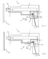
- the safety device 8 of the tool 1 functions as follows.
- Fig. 1a the control volume 15 is charged via the charging connection 27.1.
- the tool 1 is then placed in a ready-to-release state or a secured state.
- the tool 1 has a pneumatic line, which is both part of the charging connection 27.1 and part of the discharge connection 33.1 and which extends from the activation element 33 to the control volume 15.
- the tool 1 further has two separate lines, one of the separate lines being part of the charging connection 27.1 and extending from the activation element 33 to the gas pressure source connection 23 and the other of the separate lines being part of the discharge connection 33.1 and extending from the activation element 33 extends to the pressure sink 40.
- the smallest flow cross section, which determines the delay time of the securing device 8 together with the gas pressure, is present in exactly one of the separate lines, here in the line which extends from the activating element 33 to the pressure sink 40.
- the fast loading and slow unloading of the control volume 15 is thereby realized constructively very advantageous.
- the securing device 8 is set up to transfer the tool 1 into the secured state when the pressure falls below a threshold in the control volume and that the charging connection 27.1 is present when the trigger element 6 is in its idle state 600.
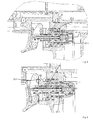
- Fig. 2-8 show sectional views of a still further preferred embodiment of a tool 1 based on Fig. 1a, 1b in different states. It rejects the in Fig. 1 a and 1 b shown and described features.
- FIGS. 2 and 3 show the tool 1 when no compressed air is connected, the standby element 27 is in the securing position.
- Fig. 4 shows the tool 1 with connected compressed air, wherein neither trigger element 6 nor workpiece contact element 7 are actuated - the standby element 27 is in the standby position.
- Fig. 5 shows the tool 1 with trigger element 6 pressed and with the standby element 27 still in the ready position, Fig. 6 the tool 1, after the predetermined time has expired and the tool 1 has been transferred to the secured state, the standby element 27 is now in the securing position.
- Fig. 7 shows the tool 1 in the state of triggering a driving operation, the standby element 27 is in the standby position, Fig. 8 the tool while pressed trigger element 6 and workpiece contact element 7, wherein it is in the secured state - the standby element 27 is in the safety position - and therefore no driving operation is triggered.
- the activation element 33 can be pneumatically reset to that from its first and second position, in which the activation element 33 is in the idle state 600 of the trigger element 6.
- the activation element 33 has a positive surface difference of areas, which are acted upon by gas of the gas pressure source minus surfaces which are connected to the pressure sink 40.
- the securing device 8 has a standby element 27 which can be displaced pneumatically into a securing position and a ready position.
- the tool 1 is in the secured state ( Fig. 2, 3rd . 6 . 8th ) when the standby element 27 is in the safing position and is in the ready to trip state 100 (FIG. Fig. 4, 5 . 7 ) when the standby element 27 is in the standby position.
- the standby element 27 is arranged between the control volume 15 and the gas pressure source connection 23, and the charge connection 27.1 is passed through at least two openings of the standby element 27 ( Fig. 4 ).
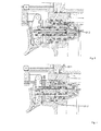
- the standby element 27 has a first surface area with a first surface area A1, which can be acted upon by gas pressure of the control volume 15 when the trigger element 6 is in its depressed state 601. It has a second surface area with a second area A2, which can be acted on by gas pressure of the gas pressure source when the trigger element 6 is in its depressed state 601 and when the trigger element 6 is in its idle state 600.
- the first and second surface areas are adapted to direct displacement forces applied to the standby element 27 upon application of pressure. For this they have opposite components of surface normals.
- the first and second surface areas are in a common pneumatic volume when the activation element 33 is in the first position (left or closer to the trigger element) and in two separate volumes when the activation element 33 is in the second Position (on the right or away from the trigger element).
- the first area A1 is greater than the second area A2.
- the standby element 27 is designed as a tube piece, which is open at both end faces and has a central passage 27.3.
- the pipe section has, in addition to the passage 27.3, an axial secondary passage 27.4 which has an opening facing the passage 27.3 and an opening axially spaced therefrom and facing the outside environment of the pipe section.
- the secondary channel 27.4 is part of the charging connection 27.1 (FIG. Fig. 4 ).
- the activation element 33 is movably guided on the standby element 27 as well as relative to the standby element 27.
- the activation element 33 and the standby element 27 are inserted into each other and concentric.
- Outer seal rings 33.2, 33.3, 33.4, 33.5, 33.6, 33.7 of the activation element 33 abut the inner contour of the standby element 27 directly.
- the activation element 33 is also formed as a pipe piece.
- the discharge connection 33.1 extends through two openings of the activation element 33 present in a lateral surface of the activation element 33.1 (FIG. Fig. 5 ). By the activation element 33, the discharge connection 33.1 is defined in the activation position (second position, right).
- the tool 1 has a main triggering valve 12 and a triggering element 21, which is set up to provide a pneumatic triggering connection 21.1 (FIG. Fig. 5 ) from the gas pressure source port 23 to the main trigger valve 12 when the standby element 27 is in the standby position.
- a pneumatic secondary line 27.2 is provided, bypassing the triggering element 21 between the main triggering valve 12 and the gas pressure source connection 23, when the standby element 27 is in the securing position ( Fig. 6 ) or when the activation element 33 in the first position, left ( Fig. 4 ) is located.
- the activation element 33 defines part of the triggering connection 21.1 from the gas pressure source connection 23 to the main triggering valve 12 (FIG. Fig. 5 ).
- the triggering element 21 is movably guided on the activating element 33 and relative to the activating element 33.
- the activation element 33 and the trigger element 21 are inserted into one another.
- the triggering element 21 is here set up to define a pneumatic triggering discharge connection 21.2 between the main triggering valve 12 and the pressure sink 40.
- the trigger element 6 has a coupling element 26 which can be acted upon by the workpiece contact element 7 in any position of the trigger element 21 and which mechanically couples the workpiece contact element 7 and the trigger element 6 to the trigger element 21.
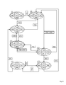
- FIG. 12 is a flowchart illustrating the use of the further preferred embodiment of a tool based on the previous figures in various states, some of which are illustrated in the previous figures (cross references indicated by Roman numerals). States are each circled, events outlined in an angular manner.
- state I the tool 1 is not connected to the gas pressure source. Therefore, the tool is in the locked state 101.
- the trigger element 6 is in the idle state 600, the workpiece contact element 7 in the unactuated state 700.
- the safety device 8 is not active, i. there is no time counter.
- the standby element 27 may be in either the backup position (left position) or the standby position (right position) in this state.
- the tool 1 is then used by connecting 230 to the gas pressure source, whereby the device assumes the triggering state 100.
- the standby element 27 (if it has not already been there in state I) is moved into its standby position. This is due to the area difference causes the surface areas A1 and A2, which are both acted upon in this state by the pressure of the gas pressure source.
- the control volume 15 is “charged” with gas pressure.
- there is a secondary line 27.2 in this state which represents a bridging of the trigger element 21.
- the secondary line 27.2 is thus a non-interruptible from the trigger element 21 connection from the gas pressure source port 23 to the main trigger valve 12th
- a next process state can be achieved (left, second line) in which the workpiece contact element 7 is then in its actuated state 701.
- Trigger element 6 is in the depressed state 601, workpiece contact element 7 in the actuated state 701.
- the trigger element 21 is in its release position, which is achieved by means of the coupling element 26.
- the trip connection 21.1 is made by the main trigger valve 12 to the pressure sink 40, so that the main trigger valve 12 is activated and the driving is performed.
- the driving volume 13 is acted upon by the gas pressure of the gas pressure source, so that the working piston moves in the direction of the tool tip (to the left).
- the working piston 11 moves back to its rest position, so that the control volume 15 then can not be loaded via the ventilation assembly 18 - the elastic Since the trigger element 6 is pressed, 601, and thus the discharge connection 33.1 is made, the pressure in the control volume 15 gradually decreases, ie the countdown is running, the safety device 8 is activated.
- state III can also be reached by pressing 610 of the trigger element 6 in state II, which also the safety device 8 is activated and thus starts a countdown for moving the tool 1 in the secure state 101.
- the control volume 15 has been charged by the charging connection 27.1 in state II and is then slowly discharged via the discharge connection 33.1.
- control volume 15 is separated from the gas pressure source (while, for example, in state II has a connection between these on the charging connection 27.1) and air escapes through the discharge connection 33.1, so that the standby element 27 abruptly after expiry of the predetermined time in the direction the securing position moves.
- the ready element 27 has arrived in the securing position (left position).
- the standby element 27 allows in this position, a secondary line 27.2, which connects the main trigger valve 12 with the gas pressure of the gas pressure source, so that no matter in which position is triggering element 21 or activation element 33, no interruption of this connection is possible.
- an interruption would be necessary to initiate a drive-in process. Therefore, no triggering is possible and thus the tool 1 is in the secured state 101.
- an operation 710 of the workpiece contact element 7, which leads to the state VI and shifts the triggering element into its triggering position can not cause a triggering, since the standby element 27 the secondary line 27.2 defines. In order to emerge from the saved state 101, the user must release the trigger element 6 620.
- Fig. 10-Fig. 12 show, based on the previous figures, a variant in which the activation element 33 is also displaceable by means of the workpiece contact element 7.
- the workpiece contact element 7 is mechanically coupled to the activation element 33 such that the workpiece contact element 7 can press the activation element 33 into the activation position (right position); this condition is in FIGS. 11 and 12 shown, wherein the standby element 27 in Fig. 11 is in the ready position and in Fig. 12 in the hedging position.
- This additional mechanical coupling to the activation element 33 is here by way of example and roughly indicated by means of an angled region of the workpiece contact element 7.
- the workpiece contact element 7 is as previously set up to press the triggering element 21 via the coupling element 26. Only when both elements of trigger element 6 and workpiece contact element 7 are unactuated or in the idle state, the activation element 33 can move out of the activation position.
- Fig. 13 shows a flowchart for this variant of Fig. 10-12 , where again states with Roman numbers are referenced - the states II-VI can the Fig. 2-8 are removed, with only the changed mechanical coupling between activation element 33 and workpiece contact element 7 makes a difference, the state otherwise, however, is the same.
- the process builds on the in Fig. 9 shown process;
- the securing device 8 is now already activated by pressing 710 of the workpiece contact element 7, so that it is now in the state VII in the activated state 801, because by the workpiece contact element 7, the activation element 33 is moved to the left position, so that the discharge connection 33.1 is made.
Abstract
Eintreibwerkzeug (1) zum Eintreiben von Befestigungsmitteln (90) in ein Werkstück (91) wobei das Werkzeug (1) insbesondere aufweist: - eine Sicherungseinrichtung (8), welche mit dem Triggerelement (6) gekoppelt ist und eingerichtet ist, nach Ablauf (820) einer von einer Aktivierung (810) der Sicherungseinrichtung (8) ausgehenden Verzögerungszeit eine Überführung des Eintreibwerkzeugs (1) von einem auslösebereiten Zustand (100) in einen gesicherten Zustand (101) zu bewirken, ª wobei die Sicherungseinrichtung (8) ein Steuervolumen (15) aufweist ª wobei die Sicherungseinrichtung (8) ein Aktivierungselement (33) aufweist, welches mittels des Triggerelements (6) zwischen einer ersten und einer zweiten Position wechselbar ist, wobei in der ersten Position des Aktivierungselements (33) eine erste pneumatische Verbindung zwischen dem Steuervolumen (15) und dem Gasdruckquellenanschluss (23) definiert ist, die im Folgenden Ladeverbindung (27.1) genannt wird, und wobei in der zweiten Position des Aktivierungselements (33) eine zweite pneumatische Verbindung zwischen dem Steuervolumen (15) und einer Drucksenke (40) definiert ist, die im Folgenden Entladeverbindung (33.1) genannt wird, wobei eine aus der Ladeverbindung (27.1) und der Entladeverbindung (33.1) einen kleinsten Strömungsquerschnitt aufweist, welcher zusammen mit einem Gasdruck der Gasdruckquelle die Verzögerungszeit der Sicherungseinrichtung (8) bestimmt. Die Erfindung betrifft weiterhin ein entsprechendes Verfahren zum Betreiben eines Eintreibwerkzeugs.Driving tool (1) for driving fasteners (90) into a workpiece (91), the tool (1) having in particular: - a safety device (8), which is coupled to the trigger element (6) and is set up, after expiry (820) of a delay time emanating from an activation (810) of the safety device (8), to transfer the driving tool (1) from a state ready for deployment (100) to bring about a secured state (101), ª wherein the safety device (8) has a control volume (15). ªª wherein the safety device (8) has an activation element (33) which can be changed between a first and a second position by means of the trigger element (6), wherein in the first position of the activation element (33) a first pneumatic connection is defined between the control volume (15) and the gas pressure source connection (23), which is referred to below as the charging connection (27.1), and wherein in the second position of the activation element (33) a second pneumatic connection is defined between the control volume (15) and a pressure sink (40), which is referred to below as the discharge connection (33.1), one of the charging connection (27.1) and the discharging connection (33.1) having a smallest flow cross-section which, together with a gas pressure from the gas pressure source, determines the delay time of the safety device (8). The invention also relates to a corresponding method for operating a driving tool.
Description
Die Erfindung betrifft ein Eintreibwerkzeug zum Eintreiben von Befestigungsmitteln in ein Werkstück mittels Eintreibzyklen, bei denen eine Sicherungseinrichtung ein unbeabsichtigtes Auslösen bei betätigtem Trigger nach einer vorbestimmten Zeit unterbinden soll.The invention relates to a driving tool for driving fasteners into a workpiece by means of driving cycles, in which a securing device is intended to prevent unintentional triggering when the trigger is actuated after a predetermined time.
Ein gattungsgemäßes Eintreibwerkzeug ist im wertvollen Beitrag zum Stand der Technik
Die
Der Erfinder befand den Stand der Technik insofern als nachteilig, als zur Erhöhung der Sicherheit die Flexibilität der Werkzeugnutzung eingeschränkt ist und/oder ein aufwendiger konstruktiver Aufbau notwendig ist. Aufgabe der vorliegenden Erfindung war es, die Nachteile des Stands der Technik zu verbessern, insbesondere die Flexibilität der Werkzeugnutzung zu erhöhen und dabei eine vergleichbare Sicherheit zu gewährleisten.The inventor found the prior art to be disadvantageous insofar as the flexibility of the use of tools is limited to increase the safety and / or a complicated structural design is necessary. Object of the present invention was to improve the disadvantages of the prior art, in particular to increase the flexibility of the tool use and to ensure a comparable security.
Die Aufgabe wird durch die unabhängigen Ansprüche gelöst. Vorteilhafte Weiterbildungen sind in den Unteransprüchen definiert.The object is solved by the independent claims. Advantageous developments are defined in the subclaims.
Insbesondere wird die Aufgabe gelöst durch ein Eintreibwerkzeug zum Eintreiben von Befestigungsmitteln in ein Werkstück wobei das Werkzeug aufweist:
- eine Aktuatoreinheit, mittels der die Befestigungsmittel in Eintreibzyklen in das Werkstück eintreibbar sind,
- eine Auslöseanordnung, mittels der die Eintreibzyklen der Aktuatoreinheit auslösbar sind, wobei die Auslöseanordnung ein Triggerelement aufweist, das handbetätigbar ist und einen Ruhezustand sowie einen gedrückten Zustand aufweist, wobei die Auslöseanordnung weiterhin ein Werkstückkontaktelement aufweist, das durch das Aufsetzen des Eintreibwerkzeugs auf das Werkstück betätigbar ist,
- einen Gasdruckquellenanschluss, an den eine Gasdruckquelle anschließbar ist,
- eine Sicherungseinrichtung, welche mit dem Triggerelement gekoppelt ist und eingerichtet ist, nach Ablauf einer von einer Aktivierung der Sicherungs-einrichtung ausgehenden Verzögerungszeit eine Überführung des Eintreibwerk-zeugs von einem auslösebereiten Zustand in einen gesicherten Zustand zu bewirken,
- ▪ wobei die Sicherungseinrichtung ein Steuervolumen aufweist,
- ▪ wobei die Sicherungseinrichtung ein Aktivierungselement aufweist, welches mittels des Triggerelements zwischen einer ersten und einer zweiten Position wechselbar ist, wobei in der ersten Position des Aktivierungselements eine pneumatische Verbindung zwischen dem Steuervolumen und dem Gasdruckquellenanschluss definiert ist, die im Folgenden Ladeverbindung genannt wird,
wobei, bevorzugt mindestens, eine aus der Ladeverbindung und der Entladeverbindung einen kleinsten Strömungsquerschnitt aufweist, welcher zusammen mit einem Gasdruck der Gasdruckquelle die Verzögerungszeit der Sicherungseinrichtung bestimmt.
- an actuator unit, by means of which the fastening means in drive-in cycles in the Workpiece can be driven in,
- a trigger arrangement by means of which the drive-in cycles of the actuator unit can be triggered, the trigger arrangement having a trigger element which is manually operable and has an idle state and a pressed state, wherein the trigger arrangement further comprises a workpiece contact element that can be actuated by placing the drive-in tool on the workpiece .
- a gas pressure source connection, to which a gas pressure source can be connected,
- a safety device, which is coupled to the trigger element and is set up to effect a transfer of the drive-in tool from a trigger-ready state into a secured state after the expiry of a delay time which is triggered by activation of the safety device,
- ▪ wherein the securing device has a control volume,
- Wherein the securing device has an activation element, which is exchangeable by means of the trigger element between a first and a second position, wherein in the first position of the activation element a pneumatic connection between the control volume and the gas pressure source connection is defined, which is called charging connection in the following,
wherein, preferably at least, one of the charging connection and the discharge connection has a smallest flow cross-section which, together with a gas pressure of the gas pressure source, determines the delay time of the securing device.
Die Aufgabe wird weiterhin insbesondere gelöst durch ein Verfahren zum Eintreiben von Befestigungsmitteln in ein Werkstück
- wobei die Befestigungsmittel mittels einer Aktuatoreinheit in Eintreibzyklen in das Werkstück eingetrieben werden,
- wobei mittels einer Auslöseanordnung die Eintreibzyklen der Aktuatoreinheit ausgelöst werden, wobei ein Triggerelement der Auslöseanordnung handbetätigt wird und dabei von einem Ruhezustand in einen gedrückten Zustand gebracht wird, wobei ein Werkstückkontaktelement durch das Aufsetzen des Eintreibwerkzeugs auf das Werkstück betätigt wird,
- wobei ein Gasdruckquellenanschluss, an eine Gasdruckquelle angeschlossen wird,
- wobei eine mit dem Triggerelement gekoppelte Sicherungseinrichtung nach einer von einer Aktivierung der Sicherungseinrichtung ausgehenden Verzögerungszeit eine Überführung des Eintreibwerkzeugs von einem auslösebereiten Zustand in einen gesicherten Zustand bewirkt,
indem ein Aktivierungselement mittels des Triggerelements zwischen einer ersten und einer zweiten Position gewechselt wird,
wobei in der ersten Position des Aktivierungselements eine erste pneumatische Verbindung zwischen dem Steuervolumen und dem Gasdruckquellenanschluss definiert wird, die im Folgenden Ladeverbindung genannt wird,
und wobei in der zweiten Position des Aktivierungselements eine zweite pneumatische Verbindung zwischen einem Steuervolumen der Sicherheitseinrichtung und einer Drucksenke definiert wird, die im Folgenden Entladeverbindung genannt wird,
wobei durch, bevorzugt mindestens, eine aus der Ladeverbindung und der Entladeverbindung ein maximale Gasströmung strömt, welche die Verzögerungszeit der Sicherungseinrichtung bestimmt.
- wherein the fastening means are driven into the workpiece by means of an actuator unit in drive-in cycles,
- wherein the triggering cycles of the actuator unit are triggered by means of a triggering arrangement, wherein a trigger element of the triggering arrangement is manually operated and is brought from a rest state into a pressed state, wherein a workpiece contact element is actuated by placing the driving tool on the workpiece,
- wherein a gas pressure source connection is connected to a gas pressure source,
- wherein a security device coupled to the trigger element causes a transfer of the driving tool from a ready-to-release state into a secured state after a delay time which starts from an activation of the security device,
by changing an activation element between a first and a second position by means of the trigger element,
wherein in the first position of the activation element a first pneumatic connection between the control volume and the gas pressure source connection is defined, which will be referred to as a charge connection hereinafter,
and wherein in the second position of the activation element, a second pneumatic connection between a control volume of the safety device and a pressure sink is defined, which is referred to below as the discharge connection,
wherein through, preferably at least, one of the charging connection and the discharge connection flows a maximum gas flow, which determines the delay time of the securing device.
Im Gegensatz zum eingangs genannten Eintreibwerkzeug wird die Flexibilität der Werkzeugnutzung erhöht, da die Sicherungseinrichtung unabhängig von dem Zustand des Werkstückkontaktelements aktivierbar ist und somit nicht erst ein erster Einzelauslösebetriebs-Eintreibzyklus vorgenommen werden muss, um die Sicherungseinrichtung zum ersten Mal zu aktivieren. Der Benutzer kann von Beginn an das Werkzeug nach Wahl im Einzelauslösebetriebs oder im Kontaktauslösebetrieb betreiben. Gleichzeitig wird dabei eine vergleichbare Sicherheit erhalten, da die Sicherheitseinrichtung das Werkzeug nach wie vor nach einer vorbestimmten Verzögerungszeit in einen gesicherten Zustand überführt, so dass selbst wenn der Benutzer versehentlich das Triggerelement drückt bevor er einen ersten Eintreibzyklus ausgelöst hat, ein unbeabsichtigtes Auslösen eines Eintreibzyklus nur innerhalb der vorbestimmten Verzögerungszeit möglich ist, ansonsten jedoch nicht. Hierfür weist das Werkzeug ein Aktivierungselement auf, mittels dessen eine Aktivierung der Sicherungseinrichtung an die Triggerbewegung gekoppelt ist, indem die Verschiebung des Aktivierungselements durch das Triggerelement bei Drücken des Triggerelements dafür genutzt wird, eine Aktivierung der Sicherheitseinrichtung zu veranlassen.In contrast to the driving tool mentioned above, the flexibility of the tool use is increased, since the securing device can be activated independently of the state of the workpiece contact element and thus not first a first single trip operation-driving cycle must be made to activate the safety device for the first time. From the beginning, the user can operate the tool in individual trip mode or in contact tripping mode. At the same time a comparable security is obtained since the safety device still transfers the tool to a secured state after a predetermined delay time, so that even if the user inadvertently presses the trigger element before triggering a first drive-in cycle, an unintentional triggering of a drive-in cycle only occurs within the predetermined delay time is possible, but not otherwise. For this purpose, the tool has an activation element, by means of which an activation of the securing device is coupled to the trigger movement, in that the displacement of the activation element by the trigger element is used when the trigger element is pressed to cause an activation of the safety device.
Befestigungsmittel sind z.B. Nägel, Stifte oder spezielle eintreibbare Schrauben. Als Werkstück kommt z.B. Holz, Metall oder Beton in Betracht.Fasteners include nails, pins or special retractable screws. As a workpiece, for example, wood, metal or concrete into consideration.
Die Aktuatoreinheit ist bevorzugt eine pneumatische Aktuatoreinheit, bei welcher der für das Eintreiben notwendige Kraftaufwand rein aus pneumatischer Energie bereitgestellt wird. Die Aktuatoreinheit weist bevorzugt einen in einem Arbeitszylinder geführten Arbeitskolben auf. Die Aktuatoreinheit weist dabei bevorzugt ein Hauptauslöseventil auf, bevorzugt ein Rückschlagventil, mittels welchem der Arbeitszylinder schlagartig mit Druckluft befüllbar ist, so dass der Eintreibkolben in Richtung Werkzeugspitze bewegt wird. Der Arbeitskolben ist bevorzugt mit einem Eintreibstempel verbunden, welcher das einzutreibende Befestigungsmittel beaufschlagt. Ein Eintreibzyklus ist ein wiederkehrender Ablauf, welchen die Aktuatoreinheit zum aufeinanderfolgenden Eintreiben von Befestigungsmitteln ausführt.The actuator unit is preferably a pneumatic actuator unit, in which the force required for driving force is provided purely from pneumatic energy. The actuator unit preferably has a working piston guided in a working cylinder. The actuator unit preferably has a main triggering valve, preferably a check valve, by means of which the working cylinder can be suddenly filled with compressed air, so that the driving piston is moved in the direction of the tool tip. The working piston is preferably connected to a Eintreibstempel which acts on the einzutreibende fastener. A drive-in cycle is a recurring process that the actuator unit performs to sequentially drive fasteners.
Die Auslöseanordnung weist bevorzugt ein rein mechanisch über Festkörper (ohne fluid) mit dem Triggerelement gekoppeltes Auslöseventil auf. Das Auslöseventil ist bevorzugt in einem Auslöseventilgehäuse aufgenommen, welches separat zu dem Gehäuse des Werkzeugs ist und somit einfach auswechselbar oder nachrüstbar ist. Bevorzugt ist das Aktivierungselement in dem Auslöseventilgehäuse aufgenommen. Das Aktivierungselement ist bevorzugt Teil des Auslöseventils.The triggering arrangement preferably has a triggering valve which is coupled purely mechanically via solids (without fluid) to the trigger element. The trigger valve is preferably accommodated in a trigger valve housing, which is separate from the housing of the tool and thus is easily replaceable or retrofittable. Preferably, the activation element is received in the trigger valve housing. The activation element is preferably part of the triggering valve.
Im auslösebereiten Zustand ist es für den Benutzer möglich, einen Eintreibzyklus auszulösen - im gesicherten Zustand ist dies dem Benutzer nicht möglich.In the ready-to-operate state, it is possible for the user to initiate a drive-in cycle - this is not possible for the user in the safe state.
Das Steuervolumen ist bevorzugt ein Innenraum des Werkzeugs, welcher zur temporären Speicherung von pneumatischer Energie eingerichtet ist. Es ist bevorzugt direkt an den Arbeitszylinder des Werkzeugs, welcher den Arbeitskolben beinhaltet, angrenzend im Werkzeug angeordnet. Bevorzugt umgibt es die Mantelfläche des Arbeitszylinders zumindest in einem Bereich vollständig um 360°. Bevorzugt weist das Werkzeug eine Belüftungsanordnung (z.B. Öffnungen im Arbeitszylinder) auf, mittels welcher das Steuervolumen im Laufe eines Eintreibvorgangs mit Druckluft befüllbar ist.The control volume is preferably an interior of the tool, which is set up for the temporary storage of pneumatic energy. It is preferably arranged directly on the working cylinder of the tool, which includes the working piston, adjacent in the tool. Preferably, it surrounds the lateral surface of the working cylinder at least in a region completely by 360 °. Preferably, the tool has a venting arrangement (e.g., openings in the working cylinder) by means of which the control volume can be filled with compressed air during a driving operation.
Das Triggerelement kann z.B. schwenkbar oder linear schiebbar sein, z.B. ein Hebel oder Knopf. Es ist bevorzugt mittels einer Feder in den Ruhezustand vorgespannt. Bevorzugt ist das Triggerelement eingerichtet, (auch) bei unbetätigtem Werkstückkontaktelement die Sicherungseinrichtung durch einen Wechsel von seinem Ruhezustand in den gedrückten Zustand zu aktivieren.The trigger element may e.g. be pivotable or linearly slidable, e.g. a lever or button. It is preferably biased by a spring in the resting state. Preferably, the trigger element is set up (also) to activate the safety device by a change from its idle state to the depressed state when the workpiece contact element is unactuated.
Eine aus der ersten und der zweiten Position des Aktivierungselements ist bevorzugt eine Aktivierungsposition zur Aktivierung der Sicherheitseinrichtung, d.h. dass ein Wechsel des Aktivierungselements von der anderen Position in die Aktivierungsposition das Ablaufen einer Verzögerungszeit starten lässt, bevor dann die Sicherungseinrichtung das Werkzeug in den gesicherten Zustand überführt. Das Aktivierungselement befindet sich bevorzugt in der Aktivierungsposition, wenn sich das Triggerelement im gedrückten Zustand befindet. Bevorzugt ist diejenige pneumatische Verbindung aus Ladeverbindung und Entladeverbindung, welche mittels des Aktivierungselements in der Aktivierungsposition bereitgestellt ist, die Verbindung, welche den kleinsten Strömungsquerschnitt aufweist, welcher zusammen mit dem Gasdruck der Gasdruckquelle die Verzögerungszeit bestimmt. Bevorzugt ist diese Verbindung die Entladeverbindung, d.h. über welche Luft aus dem Steuervolumen zur Drucksenke fließt. Bevorzugt verläuft die Entladeverbindung durch eine, bevorzugt zwei (bevorzugt in einer Mantelfläche eines als Rohrstück ausgebildeten Aktivierungselements vorhandenen) Öffnungen des Aktivierungselements. Bevorzugt bildet diese Öffnung einen kleinsten Strömungsquerschnitt, welcher zusammen mit dem Gasdruck die vorbestimmte Verzögerungszeit definiert. Bevorzugt ist in dieser Öffnung eine Einstellnadel angeordnet, welche bevorzugt konisch zulaufend ist und somit der Strömungsquerschnitt der Öffnung durch verschieben der Nadel verändert werden kann. Durch die Nadel wird ein besonders kleiner Strömungsquerschnitt erreicht, bevorzugt kleiner als mit einem konventionellen Bohrer erreicht werden kann.One of the first and the second position of the activation element is preferably an activation position for activating the safety device, ie that a Changing the activation element from the other position into the activation position can start the expiration of a delay time, before then the safety device transfers the tool in the secured state. The activation element is preferably in the activation position when the trigger element is in the depressed state. Preferably, the pneumatic connection of charging connection and discharge connection, which is provided by means of the activation element in the activation position, the compound having the smallest flow cross-section, which determines the delay time together with the gas pressure of the gas pressure source. This connection is preferably the discharge connection, ie via which air flows from the control volume to the pressure sink. Preferably, the discharge connection extends through one, preferably two (preferably in a lateral surface of an activation element designed as a pipe piece) openings of the activation element. Preferably, this opening forms a smallest flow cross-section, which defines the predetermined delay time together with the gas pressure. Preferably, a setting needle is arranged in this opening, which is preferably tapered and thus the flow cross-section of the opening can be changed by moving the needle. Through the needle, a particularly small flow cross-section is achieved, preferably smaller than can be achieved with a conventional drill.
Aufgrund des kleinsten Strömungsquerschnitts weist die eine aus der Ladeverbindung und der Entladeverbindung einen hohen Strömungswiderstand auf, welcher ein langsames Entladen oder Laden (je nach Fall) ermöglicht.Due to the smallest flow cross-section, one of the charging connection and the discharging connection has a high flow resistance, which enables slow discharging or charging (as the case may be).
Bevorzugt ist die Sicherungseinrichtung eingerichtet, das Werkzeug von dem gesicherten Zustand in den auslösebereiten Zustand zu überführen (und bevorzugt dieses darin stabil zu halten), wenn das Werkzeug an eine Energieversorgung angeschlossen ist und sich das Triggerelement in dessen Ruhezustand befindet. Hierdurch wird der auslösebereite Zustand des Werkzeugs als Standardzustand definiert, so dass der Benutzer das Gerät bei nicht gedrücktem Trigger und angeschlossener Energiequelle im auslösebereiten Zustand vorfindet und der auslösebereite Zustand nicht erst durch einen ersten speziellen Eintreibzyklus (z.B. Einzelauslösung) erreicht werden muss.Preferably, the securing device is set up to transfer the tool from the secured state into the ready-to-trigger state (and preferably to keep it stable therein) when the tool is connected to a power supply and the trigger element is in its idle state. This defines the triggering state of the tool as the default state, so that the user finds the device in the ready-to-trigger state with the trigger disconnected and the power source connected, and the trip-ready state need not be achieved by a first special drive cycle (e.g., single trip).
Eine Aktivierung der Sicherungseinrichtung wird bevorzugt als ein Aktivieren eines Countdowns verstanden, wobei der Countdown solange läuft wie die Sicherungseinrichtung aktiviert ist - die Sicherungseinrichtung wird bevorzugt deaktiviert, indem sie zurückgesetzt wird (entweder durch einen Eintreibvorgang oder indem der Trigger - oder in einer bevorzugten Variante nach
Bevorzugt ist die Sicherungseinrichtung zurücksetzbar durch einen Eintreibzyklus (wobei der Eintreibzyklus nur solang möglich ist, wie die Sicherheitseinrichtung noch nicht eine Überführung des Werkzeugs in den gesicherten Zustand bewirkt hat) oder durch einen Wechsel des Triggerelements - oder in einer bevorzugten Variante nach
In einem weiteren Ausführungsbeispiel der vorliegenden Erfindung weist die entsprechend andere aus der Ladeverbindung und der Entladeverbindung einen größeren kleinsten Strömungsquerschnitt auf als die eine aus der Ladeverbindung und der Entladeverbindung. In einem weiteren erfindungsgemäßen Verfahren strömt durch die entsprechend andere pneumatische Verbindung bei gleichem angelegten Druck eine stärkere Gasströmung, als in der einen Verbindung.In another embodiment of the present invention, the corresponding one of the charging connection and the discharging connection has a larger smallest flow area than the one of the charging connection and the discharging connection. In a further inventive method flows through the corresponding other pneumatic connection at the same applied pressure a stronger gas flow, as in the one connection.
Hierdurch kann, nachdem der Trigger (ohne eine Auslösung zu verursachen) so lange gedrückt gehalten wurde, dass die Sicherheitseinrichtung das Werkzeug in den gesicherten Zustand überführt hat, der ungesicherte Zustand schneller wieder eingenommen werden, d.h. innerhalb einer kürzeren Zeitdauer als die Verzögerungszeit, was z.B. bei ausreichend großem minimalen Strömungsquerschnitt der anderen aus der Ladeverbindung und der Entladeverbindung sogar als augenblicklich wahrnehmbar sein kann. Aufgrund des größeren kleinsten Strömungsquerschnitts weist die andere aus der Ladeverbindung und der Entladeverbindung einen niedrigen Strömungswiderstand auf, welcher ein schnelles Entladen oder Laden (je nach Fall) ermöglicht.As a result, after the trigger (without causing a trigger) has been kept pressed so long that the safety device has transferred the tool in the secured state, the unsecured state can be resumed faster, ie within a shorter time than the delay time, which eg with a sufficiently large minimum flow cross-section of the other from the charging connection and the discharge connection can even be perceived as instantaneous. Due to the larger smallest flow cross section has the other from the charging connection and the discharge connection to a low flow resistance, which allows a fast discharging or charging (as the case may be).
In einem weiteren Ausführungsbeispiel der vorliegenden Erfindung weist das Werkzeug eine pneumatische Leitung auf, welche sowohl Teil der Ladeverbindung als auch Teil der Entladeverbindung ist und welche sich von dem Aktivierungselement hin zum Steuervolumen erstreckt, und wobei das Werkzeug weiterhin zwei voneinander getrennte Leitungen aufweist, wobei eine der voneinander getrennten Leitungen ein Teil der Ladeverbindung ist und sich von dem Aktivierungselement hin zum Gasdruckquellenanschluss erstreckt und die andere der voneinander getrennten Leitungen Teil der Entladeverbindung ist und sich von dem Aktivierungselement hin zur Drucksenke erstreckt, wobei der kleinste Strömungsquerschnitt, welcher zusammen mit dem Gasdruck die Verzögerungszeit der Sicherungseinrichtung bestimmt, in genau einer der voneinander getrennten Leitungen vorhanden ist.In a further embodiment of the present invention, the tool comprises a pneumatic line which is both part of the loading connection and part of the discharge connection and which extends from the activation element to the control volume, and wherein the tool further comprises two separate lines, wherein a the separate lines is a part of the charging connection and extends from the activation element to the gas pressure source connection and the other of the separate lines is part of the discharge and extends from the activation element to the pressure sink, wherein the smallest flow cross-section, which together with the gas pressure Delay time of the safety device determined in exactly one of the separate lines is present.
Hierdurch ist eine Y-Konfiguration bereitgestellt, mit dem Aktivierungselement als Knotenpunkt, mittels welcher die verschiedenen Strömungsquerschnitte von Entlade- und Ladverbindung konstruktiv vorteilhaft realisierbar sind. Als Alternative zu einer solchen Y-Konfiguration weist das Werkzeug bevorzugt eine Überbrückungsleitung auf und der kleinste Strömungsquerschnitt befindet sich in der gemeinsamen Leitung und ist mittels der Überbrückungsleitung in einer Position (aus erster und zweiter Position) des Aktivierungselements überbrückt oder parallel geschaltet und in der anderen Position des Aktivierungselements nicht überbrückt oder parallel geschaltet, so dass sich in der einen Position insgesamt ein größerer Strömungsquerschnitt ergibt als in der anderen Position.In this way, a Y-configuration is provided, with the activation element as a node, by means of which the different flow cross-sections of discharge and charging connection are structurally advantageous feasible. As an alternative to such a Y-configuration, the tool preferably has a bypass line and the smallest flow cross-section is in the common line and is bridged by means of the bypass line in a position (first and second position) of the activation element or in parallel and in the other Position of the activation element not bridged or connected in parallel, so that in the one position results in a total of a larger flow cross-section than in the other position.
In einem weiteren Ausführungsbeispiel der vorliegenden Erfindung ist die Sicherungseinrichtung eingerichtet, das Werkzeug bei Unterschreiten einer Druckschwelle in dem Steuervolumen in den gesicherten Zustand zu überführen. In einem weiteren erfindungsgemäßen Verfahren wird das Werkzeug entsprechend in den gesicherten Zustand überführt.In a further exemplary embodiment of the present invention, the securing device is set up to transfer the tool into the secured state when the pressure falls below a pressure threshold in the control volume. In a further method according to the invention, the tool is correspondingly transferred to the secured state.
Hierdurch wird die Sicherheit des Werkzeugs weiter erhöht da ein niedrigerer Druck einen stabileren Zustand darstellt als ein höherer Druck und das Werkzeug, den stabileren Zustand anstrebend (auch generell bei Fehlfunktionen) somit sicherer gesperrt wird, sollten unerwartete Ausfälle an irgendwelchen Bauteilen auftreten.As a result, the safety of the tool is further increased because a lower pressure represents a more stable state than a higher pressure and the tool, the stable state aspiring (also generally in case of malfunctions) thus locked more secure, unexpected failures should occur on any components.
In einem weiteren Ausführungsbeispiel der vorliegenden Erfindung liegt die Ladeverbindung dann vor, wenn sich das Triggerelement (und bevorzugt das Werkstückkontaktelement) in seinem Ruhezustand befindet. In einem weiteren erfindungsgemäßen Verfahren wird das Steuervolumen mit Druckluft befüllt, wenn sich das Triggerelement (und bevorzugt das Werkstückkontaktelement) in seinem Ruhezustand befindet.In a further embodiment of the present invention, the charging connection is present when the trigger element (and preferably the workpiece contact element) is in its idle state. In a further method according to the invention, the control volume is filled with compressed air when the trigger element (and preferably the workpiece contact element) is in its idle state.
Hierdurch ist das Steuervolumen bei losgelassenem Triggerelement (und bevorzugt unbetätigtem Werkstückkontaktelement) befüllbar, so dass im auslösebereiten Zustand ein hoher Luftdruck in dem Steuervolumen vorliegt.As a result, the control volume can be filled when the trigger element (and preferably the unactuated workpiece contact element) is released, so that in the ready-to-trigger state there is a high air pressure in the control volume.
In einem weiteren Ausführungsbeispiel der vorliegenden Erfindung ist das Aktivierungselement zusätzlich mittels des Werkstückkontaktelements zwischen der ersten und der zweiten Position wechselbar. In einem weiteren erfindungsgemäßen Verfahren wird das Aktivierungselement zusätzlich mittels des Werkstückkontaktelements entsprechend zwischen diesen Positionen gewechselt.In a further embodiment of the present invention, the activation element is additionally exchangeable between the first and the second position by means of the workpiece contact element. In a further method according to the invention, the activation element is additionally exchanged between these positions by means of the workpiece contact element.
Hierdurch wird die Sicherheit noch weiter erhöht, da die Sicherungseinrichtung auch dann aktivierbar ist, wenn nur das Werkstückkontaktelement betätigt wird.As a result, the security is further increased because the securing device can also be activated when only the workpiece contact element is actuated.
Bevorzugt ist das Aktivierungselement in die eine Position (bevorzugt Aktivierungsposition) durch das Triggerelement oder das Werkstückkontaktelement bringbar, d.h. es reicht eine Betätigung eines dieser Elemente aus, es können auch beide Elemente betätigt werden. Hingegen müssen beide Elemente unbetätigt sein, damit das Aktivierungselement die andere Position wieder einnehmen kann.Preferably, the activation element can be brought into the one position (preferably activation position) by the trigger element or the workpiece contact element, i. it is sufficient to actuate one of these elements, it can also be operated both elements. By contrast, both elements must be unconfirmed, so that the activation element can take the other position again.
Werkzeug gemäß einem der vorhergehenden Ansprüche wobei das Aktivierungselement pneumatisch in diejenige aus seiner ersten und zweiten Position zurücksetzbar ist, in welcher sich das Aktivierungselement im Ruhezustand des Triggerelements befindet. In einem weiteren erfindungsgemäßen Verfahren wird das Aktivierungselement pneumatisch in Richtung der entsprechenden Position bewegt.Tool according to one of the preceding claims, wherein the activation element is pneumatically resettable in that of its first and second positions, in which the activation element is in the resting state of the trigger element. In a further method according to the invention, the activation element is pneumatically moved in the direction of the corresponding position.
Hierdurch kann auf eine Rückstellfeder für das Aktivierungselement verzichtet werden. Bevorzugt weist das Aktivierungselement hierzu eine Flächendifferenz von Flächen, die durch Gas der Gasdruckquelle beaufschlagt werden abzüglich Flächen, die mit der Drucksenke verbunden sind, auf, wobei die Flächendifferenz positiv ist.This makes it possible to dispense with a return spring for the activation element. For this purpose, the activation element preferably has a surface difference of areas that are acted upon by gas of the gas pressure source minus areas that are connected to the pressure sink, wherein the area difference is positive.
In einem weiteren Ausführungsbeispiel der vorliegenden Erfindung weist die Sicherungseinrichtung ein pneumatisch in eine Sicherungsposition und eine Bereitschaftsposition verschiebbares Bereitschaftselement auf, wobei sich das Werkzeug in dem gesicherten Zustand befindet, wenn sich das Bereitschaftselement in der Sicherungsposition befindet, und wobei sich das Werkzeug in dem auslösebereiten Zustand befindet, wenn sich das Bereitschaftselement in der Bereitschaftsposition befindet. In einem weiteren erfindungsgemäßen Verfahren überführt die Sicherungseinrichtung das Eintreibwerkzeug von dem auslösebereiten Zustand in den gesicherten Zustand mittels eines pneumatischen Verschiebens eines Bereitschaftselements von einer Bereitschafts- in eine Sicherungsposition.In a further embodiment of the present invention, the securing device has a standby element pneumatically displaceable in a securing position and a standby position, wherein the tool is in the secured state when the standby element is in the securing position, and wherein the tool is in the ready-to-release state is when the standby element is in the standby position. In a further method according to the invention, the securing device transfers the driving tool from the ready-to-release state into the secured state by means of a pneumatic displacement of a stand-by element from a standby position into a securing position.
Hierdurch ist eine Ausgestaltung der Sicherungseinrichtung gegeben, welche mittels Pneumatik und des Bereitschaftselements die Sicherung/Bereitschaft des Werkzeugs ermöglicht.As a result, an embodiment of the securing device is provided, which enables the backup / readiness of the tool by means of pneumatic and the standby element.
In einem weiteren Ausführungsbeispiel der vorliegenden Erfindung ist das Bereitschaftselement, insbesondere pneumatisch bzw. strömungstechnisch, zwischen dem Steuervolumen und dem Gasdruckquellenanschluss angeordnet und die Ladeverbindung ist durch eine Öffnung des Bereitschaftselements hindurchgeführt. In einem weiteren erfindungsgemäßen Verfahren wird Gas von dem Gasdruckquellenanschluss durch eine Öffnung des Bereitschaftselements hindurch und weiter zu dem Steuervolumen geführt.In a further exemplary embodiment of the present invention, the standby element, in particular pneumatically or fluidically, is arranged between the control volume and the gas pressure source connection and the charge connection is led through an opening of the standby element. In another method of the invention, gas is passed from the gas pressure source port through an opening of the standby element and on to the control volume.
Hierdurch ist das Steuervolumen über das Bereitschaftselement mit Luft befüllbar - im Gegensatz zum eingangs genannten Eintreibwerkzeug, bei dem eine Befüllung des Steuervolumens allein über den Arbeitskolben erfolgt, ist es somit möglich, das Steuervolumen auch ohne einen Eintreibzyklus zu befüllen. Zudem wird hierdurch eine Konstruktion erhalten, mittels der eine pneumatische Sicherung erreicht werden kann, da das Bereitschaftselement einen Teil der Ladeverbindung darstellt.As a result, the control volume via the standby element with air can be filled - in contrast to the aforementioned driving tool, in which a filling of the control volume is done solely on the working piston, it is thus possible to fill the control volume without a Eintreibzyklus. In addition, a construction is thereby obtained, by means of which a pneumatic backup can be achieved because the standby element is part of the charging connection.
In einem weiteren Ausführungsbeispiel der vorliegenden Erfindung weist das Bereitschaftselement,
- einen ersten Oberflächenbereich mit einem ersten Flächeninhalt auf, der durch Gasdruck des Steuervolumens beaufschlagbar ist, wenn sich das Triggerelement in seinem gedrückten Zustand befindet, sowie
- einen zweiten Oberflächenbereich mit einem zweiten Flächeninhalt auf, der durch Gasdruck der Gasdruckquelle beaufschlagbar ist, wenn sich das Triggerelement in seinem gedrückten Zustand befindet und bevorzugt und wenn sich das Triggerelement in seinem Ruhezustand befindet;
wobei der erste und der zweite Oberflächenbereich eingerichtet sind bei Beaufschlagung von Druck entgegensetzte Verschiebungskräfteauf das Bereitschaftselement 27 zu leiten (wozu sie bevorzugt sich entgegengesetzte Komponenten von Oberflächennormalen aufweisen) und wobei der erste und zweite Oberflächenbereich sich in einem gemeinsamen pneumatischen Volumen befinden, wenn sich das Aktivierungselement in der ersten Position befindet, und sich in zwei getrennten Volumen befinden, wenn sich das Aktivierungselement in der zweiten Position befindet. In einem weiteren erfindungsgemäßen Verfahren wird das Bereitschaftselement über zwei entgegensetzte Flächenbereiche pneumatisch verschoben und die Volumen, in denen sich die Flächenbereiche jeweils befinden, werden pneumatisch miteinander (direkt, d.h. ohne wesentlichen Strömungswiderstand dazwischen) verbunden, wenn das Aktivierungselement in die erste Position gewechselt wird, und sie werden pneumatisch voneinander getrennt, wenn das Aktivierungselement in die zweite Position gewechselt wird.
- a first surface area having a first surface area, which is acted upon by gas pressure of the control volume, when the trigger element is in its depressed state, as well as
- a second surface area having a second area area through Gas pressure of the gas pressure source can be acted upon when the trigger element is in its depressed state and preferred and when the trigger element is in its rest state;
wherein the first and second surface regions are configured to direct displacement forces opposing pressure to the standby element 27 (preferably to which they have opposed components of surface normality), and wherein the first and second surface regions are located in a common pneumatic volume when the pressure is applied Activation element is in the first position, and are in two separate volumes when the activation element is in the second position. In another method according to the invention, the standby element is pneumatically displaced over two opposing surface areas and the volumes in which the surface areas are located are pneumatically connected to each other (directly, ie without significant flow resistance therebetween) when the activation element is changed to the first position, and they are pneumatically separated when the activation element is changed to the second position.
Hierdurch ist, wenn sich das Triggerelement in dessen gedrückten Zustand befindet, die Position des Bereitschaftselements durch zwei antagonistisch wirkende Oberflächenbereiche und dem Druckunterschied zwischen dem Druck im Steuervolumen und dem Druck in der Gasdruckquelle bestimmt. Da die Gasdruckquelle im Wesentlichen konstant ist, ist die Position des Bereitschaftselements daher im Wesentlichen abhängig von der Änderung des Drucks im Steuervolumen. Durch die Möglichkeit, die Volumen, in denen sich die beiden verschiedenen Flächenbereiche befinden, mittels des Aktivierungselements zu verbinden, ist ein sehr schneller Druckausgleich und somit ein sehr schnelles Rücksetzen des Bereitschaftselements aktiv durch den Benutzer mittels des Triggerelements (das mit dem Aktivierungselement gekoppelt ist) gegeben.In this way, when the trigger element is in its depressed state, the position of the standby element is determined by two antagonistic surface areas and the pressure difference between the pressure in the control volume and the pressure in the gas pressure source. Since the gas pressure source is substantially constant, the position of the standby element is therefore substantially dependent on the change in the pressure in the control volume. By the possibility of connecting the volumes in which the two different surface areas are located by means of the activation element, a very rapid pressure equalization and thus a very rapid reset of the standby element are active by the user by means of the trigger element (which is coupled to the activation element). given.
In einem weiteren Ausführungsbeispiel der vorliegenden Erfindung ist der erste Flächeninhalt größer als der zweite Flächeninhalt.In a further embodiment of the present invention, the first area is larger than the second area.
Hierdurch kann auf die Verwendung etwaiger Federn verzichtet werden, welche das Bereitschaftselement in eine Ruhelage drücken. Die Position und Positionierung des Bereitschaftselements sowie die durch das Bereitschaftselement realisierte Zeitkonstante ist somit für verschiedene Gasdrücke gleichbleibend, was mit einem Federelement mit Federkonstante, die sich nicht anderen Gasdrücken anpasst, nicht möglich ist.This makes it possible to dispense with the use of any springs that press the standby element in a rest position. The position and positioning of the standby element as well as the time constant realized by the standby element is thus constant for different gas pressures, which is not possible with a spring element with spring constant, which does not adapt to other gas pressures.
In einem weiteren Ausführungsbeispiel der vorliegenden Erfindung ist das Bereitschaftselement als Rohrstück ausgebildet, welches an beiden Stirnseiten geöffnet ist und einen zentralen Durchgangskanal aufweist.In a further embodiment of the present invention, the standby element is designed as a tubular piece, which is open at both end faces and has a central through-channel.
Hierdurch wird eine äußerst kompakte Bauform erreicht. Das Rohrstück weist bevorzugt verschiedene Außendurchmesser auf. Es ist bevorzugt in einem Ventilgehäuse verschiebbar gelagert. Das Ventilgehäuse weist bevorzugt ebenfalls analog entsprechende, verschiedene Innendurchmesser auf. Die verschiedenen Durchmesser ermöglichen eine einfache Realisierung antagonistisch wirkender Oberflächenbereiche mit unterschiedlichen Flächeninhalten.As a result, an extremely compact design is achieved. The pipe section preferably has different outer diameters. It is preferably mounted displaceably in a valve housing. The valve housing preferably also has analogously corresponding, different inner diameters. The different diameters enable a simple realization of antagonistic surface areas with different area contents.
In einem weiteren Ausführungsbeispiel der vorliegenden Erfindung weist das Rohrstück neben dem Durchgangskanal einen axialen Nebenkanal auf, welcher eine dem Durchgangskanal zugewandte, bevorzugt radial innere Öffnung aufweist sowie eine davon axial beabstandete, der Außenumgebung des Rohrstücks zugewandte, bevorzugt radial äußere Öffnung. In einem weiteren erfindungsgemäßen Verfahren wird zum Laden des Steuervolumens eine Gasströmung von dem Gasdruckquellenanschluss durch einen entsprechenden axialen Nebenkanal des Rohrstücks geleitet.In a further exemplary embodiment of the present invention, the pipe section has, in addition to the through-channel, an axial secondary channel, which has a preferably radially inner opening facing the through-channel and one of the axially spaced-apart, preferably radially outer, opening facing the outer environment of the pipe section. In a further method according to the invention, a gas flow is conducted from the gas pressure source connection through a corresponding axial auxiliary channel of the pipe section in order to load the control volume.
Hierdurch wird eine kompakte Bauform und vorteilhafte Führung der Ladeverbindung ermöglicht. Die beiden Öffnungen bilden bevorzugt jeweils das Ende des axialen Nebenkanals.As a result, a compact design and advantageous guidance of the charging connection is made possible. The two openings preferably each form the end of the axial secondary channel.
In einem weiteren Ausführungsbeispiel der vorliegenden Erfindung sind das Aktivierungselement zusammen mit dem Bereitschaftselement als Auslöseventil oder Teil des Auslöseventils der Auslöseanordnung in einem Auslöseventilgehäuse angeordnet, welches in ein Werkzeuggehäuse einsetzbar ist.In a further embodiment of the present invention, the activation element are arranged together with the standby element as a triggering valve or part of the triggering valve of the triggering arrangement in a trigger valve housing, which is insertable into a tool housing.
Hierdurch ist sind die wesentlichen bewegbaren Teile der Sicherungseinrichtung (Aktivierungselement, Bereitschaftselement) als kompakte Baugruppe zusammengefasst, die somit einfach montierbar, platzsparend und/oder nachrüstbar ist.As a result, the essential movable parts of the safety device (activation element, standby element) are summarized as a compact assembly, which is thus easy to install, save space and / or retrofitted.
In einem weiteren Ausführungsbeispiel der vorliegenden Erfindung ist das Aktivierungselement an dem Bereitschaftselement sowie relativ zu dem Bereitschaftselement beweglich geführt. In einem weiteren erfindungsgemäßen Verfahren wird das Aktivierungselement entsprechend geführt.In a further embodiment of the present invention, the activation element is movably guided on the standby element as well as relative to the standby element. In a further method according to the invention, the activation element is guided accordingly.
Hierdurch wird eine kompakte Bauform erhalten, da das Aktivierungselement und Bereitschaftselement so direkt miteinander interagieren und keine zusätzlichen Führungsteile vorgesehen werden müssen. Bevorzugt ist das Aktivierungselement von dem Bereitschaftselement aufgenommen. Bevorzugt liegt eine Kontur des Aktivierungselements oder ein Dichtungselement (z.B. Dichtungsringe) des Aktivierungselements an einer Kontur des Bereitschaftselements oder einem Dichtungselement (z.B. Dichtungsring) des Bereitschaftselements (direkt) an.As a result, a compact design is obtained because the activation element and standby element interact directly with each other and no additional guide parts must be provided. Preferably, the activation element is received by the standby element. Preferably, a contour of the activating element or a sealing element (e.g., sealing rings) of the activating element abuts a contour of the standby element or a sealing element (e.g., sealing ring) of the standby element (directly).
In einem weiteren Ausführungsbeispiel der vorliegenden Erfindung sind das Aktivierungselement und das Bereitschaftselement ineinander gesteckt und bevorzugt konzentrisch.In a further embodiment of the present invention, the activation element and the standby element are inserted into one another and preferably concentric.
Hierdurch ist die Bauform sehr kompakt. Besonders bevorzugt ist das Aktivierungselement in dem als Rohrstück ausgebildeten Bereitschaftselement konzentrisch aufgenommen, wobei eine Außenkontur des Aktivierungselements oder äußere Dichtungselemente (z.B. Dichtungsringe) des Aktivierungselements an der Innenkontur des Bereitschaftselements oder an inneren Dichtungselementen (z.B. Dichtungsringen) des Bereitschaftselements (direkt) anliegen.As a result, the design is very compact. More preferably, the activating element is concentrically received in the standby element formed as a pipe section, wherein an outer contour of the activating element or outer sealing elements (e.g., sealing rings) of the activating element abut (directly) the inner contour of the standby element or inner sealing elements (e.g., sealing rings) of the standby element.
In einem weiteren Ausführungsbeispiel der vorliegenden Erfindung ist das Aktivierungselement in der zweiten Position eingerichtet, die Ladeverbindung zu unterbrechen. In einem weiteren erfindungsgemäßen Verfahren wird die Ladverbindung durch das Aktivierungselement in der zweiten Position unterbrochen.In a further embodiment of the present invention, the activation element is arranged in the second position to interrupt the charging connection. In a further method according to the invention, the charging connection is interrupted by the activation element in the second position.
Hierdurch wird das Steuervolumen in Abhängigkeit der Triggerposition mittels des Aktivierungselements von der Gasdruckquelle getrennt, so dass sich der Gasdruck im Steuervolumen von dem der Gasdruckquelle verändern kann.As a result, the control volume is separated from the gas pressure source as a function of the trigger position by means of the activation element, so that the gas pressure in the control volume can change from that of the gas pressure source.
In einem weiteren Ausführungsbeispiel der vorliegenden Erfindung weist das Werkzeug ein Hauptauslöseventil auf und das Werkzeug weist ein Auslöseelement auf, welches eingerichtet ist, eine pneumatische Verbindung, im Folgenden Auslöseverbindung genannt, von dem Gasdruckquellenanschluss zum Hauptauslöseventil zu unterbrechen, wenn sich das Bereitschaftselement in der Bereitschaftsposition befindet, und wobei mittels des Bereitschaftselements eine pneumatische Nebenleitung unter Umgehung des Auslöseelements zwischen dem Hauptauslöseventil und dem Gasdruckquellenanschluss bereitgestellt ist, wenn sich das Bereitschaftselement in der Sicherungsposition befindet. In einem weiteren erfindungsgemäßen Verfahren wird mittels eines Auslöseelements eines Hauptauslöseventils eine Auslöseverbindung entsprechend unterbrochen und es wird eine pneumatische Nebenleitung entsprechend bereitgestellt.In a further exemplary embodiment of the present invention, the tool has a main triggering valve and the tool has a triggering element which is set up to interrupt a pneumatic connection, referred to below as a triggering connection, from the gas pressure source connection to the main triggering valve, when the standby element is in the standby position, and wherein by means of the standby element, a pneumatic bypass is provided, bypassing the trigger element between the main trigger valve and the gas pressure source port, when the standby element is in the safety position. In a further method according to the invention, a triggering connection is interrupted accordingly by means of a triggering element of a main triggering valve and a pneumatic secondary line is accordingly provided.
Hierdurch wird pneumatisch verhindert, dass eine Auslösung stattfindet, wenn sich das Bereitschaftselement in der Sicherungsposition befindet. Hingegen ist eine Auslösung mittels des Auslöseelements möglich, wenn sich das Bereitschaftselement in der Bereitschaftsposition befindet. Bevorzugt besteht ebenfalls eine solche Nebenleitung, wenn sich das Bereitschaftselement in der Bereitschaftsposition befindet und sich das Aktivierungselement nicht in der Aktivierungsposition befindet. Bevorzugt ist das Auslöseelement eingerichtet, eine pneumatische Auslöseentladeverbindung zwischen dem Hauptauslöseventil und einer Drucksenke zu definieren (und nicht nur die Auslöseverbindung zu unterbrechen), wenn sich das Bereitschaftselement in der Bereitschaftsposition befindet. Hierdurch nimmt das Auslöseelement eine Doppelfunktion ein, wodurch eine kompakte Bauform ermöglicht wird.This pneumatically prevents a triggering takes place when the standby element is in the safety position. On the other hand, a release by means of the trigger element is possible when the standby element is in the standby position. Preferably, there is also such a secondary line when the standby element is in the ready position and the activation element is not in the activation position. Preferably, the triggering element is arranged to define a pneumatic triggering discharge connection between the main triggering valve and a pressure sink (and not just to interrupt the triggering connection) when the standby element is in the ready position. As a result, the trigger element assumes a dual function, whereby a compact design is possible.
Bevorzugt weist das Triggerelement ein Kupplungselement auf, welches von dem Werkstückkontaktelement, bevorzugt in jeder Position des Auslöseelements, beaufschlagbar ist und welches das Werkstückkontaktelement mit dem Auslöseelement mechanisch koppelt.Preferably, the trigger element has a coupling element, which can be acted upon by the workpiece contact element, preferably in any position of the trigger element, and which mechanically couples the workpiece contact element with the trigger element.
Das Auslöseelement ist bevorzugt ein Stift. Bevorzugt weist das Auslöseelement Dichtungsflächen (z.B. Dichtungsringe) auf. Das Auslöseelement weist bevorzugt eine Ruheposition und eine Auslöseposition auf. Bevorzugt ist die Auslöseverbindung nur dann unterbrochen, wenn sich das Aktivierungselement in einer seiner beiden Position (z.B. die zweite Position oder die Aktivierungsposition) befindet UND sich das Auslöseelement in der Auslöseposition befindet. Hierdurch hat auch das Aktivierungselement eine Auslösefunktion, wenn es in die entsprechende Position gebracht wird, sofern sich das Auslöseelement bereits in der Auslöseposition befindet. Das Auslöseelement ist bevorzugt Teil des Auslöseventils.The triggering element is preferably a pin. The triggering element preferably has sealing surfaces (eg sealing rings). The triggering element preferably has a rest position and a triggering position. Preferably, the trigger connection is interrupted only when the activation element is in one of its two position (eg the second position or the activation position) AND the trigger element is in the release position. As a result, the activation element has a triggering function when it is brought into the appropriate position, if the triggering element is already in the release position. The triggering element is preferably part of the triggering valve.
In einem weiteren Ausführungsbeispiel der vorliegenden Erfindung definiert das Aktivierungselement einen Teil der Auslöseverbindung von dem Gasdruckquellenanschluss zum Hauptauslöseventil.In another embodiment of the present invention, the activation element defines a portion of the trip connection from the gas pressure source port to the main trigger valve.
Hierdurch wird eine sehr kompakte Bauform ermöglicht.This allows a very compact design.
In einem weiteren Ausführungsbeispiel/Verfahren der vorliegenden Erfindung ist/wird das Auslöseelement an dem Aktivierungselement und relativ zu dem Aktivierungselement beweglich geführt.In another embodiment / method of the present invention, the triggering element is / are movably guided on the activating element and relative to the activating element.
Hierdurch wird eine kompakte Bauform erhalten, da Auslöseelement und Aktivierungselement so direkt miteinander interagieren und keine zusätzlichen Führungsteile vorgesehen werden müssen. Bevorzugt liegt eine Kontur des Aktivierungselements oder ein Dichtungselement (z.B. Dichtungsringe) des Aktivierungselements an einer Kontur des Auslöseelements oder einem Dichtungselement (z.B. Dichtungsring) des Auslöseelements (direkt) an.As a result, a compact design is obtained because trigger element and activation element interact directly with each other and no additional guide parts must be provided. Preferably, a contour of the activating element or a sealing element (e.g., sealing rings) of the activating element abuts a contour of the triggering element or a sealing element (e.g., sealing ring) of the triggering element (directly).
In einem weiteren Ausführungsbeispiel der vorliegenden Erfindung sind das Aktivierungselement und das Auslöseelement ineinandergesteckt und bevorzugt konzentrisch.In a further embodiment of the present invention, the activation element and the trigger element are inserted into one another and preferably concentric.
Hierdurch ist die Bauform sehr kompakt. Bevorzugt liegen eine Außenkontur des Auslöseelements oder äußere Dichtungselemente (z.B. Dichtungsringe) des Auslöseelements an der Innenkontur des Aktivierungselements oder an inneren Dichtungselementen (z.B. Dichtungsringen) des Aktivierungselements (direkt) an.As a result, the design is very compact. Preferably, an outer contour of the trigger element or outer seal elements (e.g., seal rings) of the trigger element abut the inner contour of the activating element or inner sealing elements (e.g., sealing rings) of the activating element (directly).
Die Erfindung soll nun anhand von Zeichnungen beispielhaft weiter veranschaulicht werden. Hierbei zeigen:
-
Fig. 1a, 1b eine Prinzipdarstellung eines erfindungsgemäßen Werkzeugs, -
Fig. 2 - Fig. 8 Schnittdarstellungen einer noch weiter bevorzugten Ausführungsform eines Werkzeugs basierend aufFig. 1a, 1b in verschiedenen Zuständen, -
Fig. 9 ein Ablaufdiagramm der Verwendung einer weiter bevorzugten Ausführungsform eines Werkzeugs basierend auf den vorigen Figuren in verschiedenen Zustanden, die sich teils in den vorigen Figuren abgebildet wiederfinden, -
Fig. 10 - Fig. 12 aufbauend auf den vorigen Figuren eine Variante, in welcher das Aktivierungselement auch mittels den Werkstückkontaktelements verschiebbar ist,Fig. 13 ein Ablaufdiagramm für diese Variante.
-
Fig. 1a, 1b a schematic diagram of a tool according to the invention, -
Fig. 2-8 Sectional views of a still further preferred embodiment of a tool based onFig. 1a, 1b in different states, -
Fig. 9 3 is a flow chart of the use of a further preferred embodiment of a tool based on the previous figures in various states, which are partly depicted in the previous figures, -
Fig. 10 - Fig. 12 Based on the previous figures, a variant in which the Activation element is also displaceable by means of the workpiece contact element,Fig. 13 a flow chart for this variant.
eine Aktuatoreinheit 3, mittels der dieBefestigungsmittel 90 in Eintreibzyklen indas Werkstück 91 eintreibbar sind,eine Auslöseanordnung 5, mittels der dieEintreibzyklen der Aktuatoreinheit 3 auslösbar sind,wobei die Auslöseanordnung 5ein Triggerelement 6 aufweist, das handbetätigbar ist und einen Ruhezustand 600 (Fig. 1a ) sowie einen gedrückten Zustand 601 (Fig. 1 b) aufweist,wobei die Auslöseanordnung 5 weiterhinein Werkstückkontaktelement 7 aufweist, das durch das Aufsetzen des Eintreibwerkzeugs 1auf das Werkstück 91 betätigbar ist,einen Gasdruckquellenanschluss 23, an den eine Gasdruckquelle anschließbar ist,eine Sicherungseinrichtung 8, welchemit dem Triggerelement 6 gekoppelt ist und eingerichtet ist, nach Ablauf einer von einer Aktivierung der Sicherungseinrichtung 8 ausgehenden Verzögerungszeit eine Überführung des Eintreibwerkzeugs 1 von einem auslösebereiten Zustand in einen gesicherten Zustand zu bewirken,- ▪
wobei die Sicherungseinrichtung 8ein Steuervolumen 15 aufweist, - ▪
wobei die Sicherungseinrichtung 8ein Aktivierungselement 33 aufweist, welches mittels des Triggerelements 6 zwischen einer ersten und einer zweiten Position wechselbar ist. In der ersten Position des Aktivierungselements 33 ist eine pneumatische Verbindung zwischendem Steuervolumen 15und dem Gasdruckquellenanschluss 23 definiert, die im Folgenden Ladeverbindung 27.1 genannt wird. In der zweiten Position des Aktivierungselements 33 ist eine pneumatische Verbindung zwischendem Steuervolumen 15 und einer Drucksenke 40 definiert, die im Folgenden Entladeverbindung 33.1 genannt wird. Eine aus der Ladeverbindung 27.1 und der Entladeverbindung 33.1, hier die Entladeverbindung 33.1, weist einen kleinsten Strömungsquerschnitt auf, welcher zusammen mit einem Gasdruck der Gasdruckquelle dieVerzögerungszeit der Sicherungseinrichtung 8 bestimmt.
- ▪
- an
actuator unit 3 by means of which the fastening means 90 can be driven into theworkpiece 91 in drive-in cycles, - a
trigger arrangement 5, by means of which the drive-in cycles of theactuator unit 3 can be triggered, thetrigger arrangement 5 having atrigger element 6 which is manually actuatable and a rest state 600 (FIG.Fig. 1a ) and a depressed state 601 (Fig. 1 b) wherein thetrigger assembly 5 further comprises aworkpiece contact element 7, which can be actuated by placing thedriving tool 1 on theworkpiece 91, - a gas
pressure source connection 23, to which a gas pressure source can be connected, - a
safety device 8, which is coupled to thetrigger element 6 and is set up to effect a transfer of thedriving tool 1 from a ready-to-release state into a secured state after the expiry of a delay time proceeding from an activation of thesafety device 8,- ▪ wherein the securing
device 8 has acontrol volume 15, - Wherein the securing
device 8 has anactivation element 33, which is exchangeable by means of thetrigger element 6 between a first and a second position. In the first position of theactivation element 33, a pneumatic connection between thecontrol volume 15 and the gaspressure source connection 23 is defined, which will be referred to below as charge connection 27.1. In the second position of theactivation element 33, a pneumatic connection between thecontrol volume 15 and apressure sink 40 is defined, which is referred to below as the discharge connection 33.1. One of the charging connection 27.1 and the discharge connection 33.1, here the discharge connection 33.1, has a smallest flow cross-section which, together with a gas pressure of the gas pressure source, determines the delay time of the securingdevice 8.
- ▪ wherein the securing
Dabei funktioniert die Sicherungseinrichtung 8 des Werkzeugs 1 wie folgt. In
In diesen Figuren ist zudem die bevorzugte Ausgestaltung veranschaulicht, gemäß welcher die entsprechend andere aus der Ladeverbindung 27.1 und der Entladeverbindung 33.1, d.h. hier die Ladeverbindung 27.1, einen größeren kleinsten Strömungsquerschnitt aufweist als die eine aus der Ladeverbindung 27.1 und der Entladeverbindung 33.1, d.h. die Entladeverbindung 33.1, wodurch das Steuervolumen 15 sehr schnell geladen werden kann.These figures also illustrate the preferred embodiment, according to which the corresponding others from the charging connection 27.1 and the discharging connection 33.1, i. Here, the charging connection 27.1, a larger smallest flow cross-section than the one of the charging connection 27.1 and the discharge connection 33.1, i. the discharge connection 33.1, whereby the
Weiterhin ist die bevorzugte Ausgestaltung veranschaulicht, gemäß welcher das Werkzeug 1 eine pneumatische Leitung aufweist, welche sowohl Teil der Ladeverbindung 27.1 als auch Teil der Entladeverbindung 33.1 ist und welche sich von dem Aktivierungselement 33 hin zum Steuervolumen 15 erstreckt. Dabei weißt das Werkzeug 1 weiterhin zwei voneinander getrennte Leitungen auf, wobei eine der voneinander getrennten Leitungen ein Teil der Ladeverbindung 27.1 ist und sich von dem Aktivierungselement 33 hin zum Gasdruckquellenanschluss 23 erstreckt und die andere der voneinander getrennten Leitungen Teil der Entladeverbindung 33.1 ist und sich von dem Aktivierungselement 33 hin zur Drucksenke 40 erstreckt. Der kleinste Strömungsquerschnitt, welcher zusammen mit dem Gasdruck die Verzögerungszeit der Sicherungseinrichtung 8 bestimmt, ist in genau einer der voneinander getrennten Leitungen vorhanden, hier in der Leitung, welche sich von dem Aktivierungselement 33 hin zur Drucksenke 40 erstreckt. Das schnelle Laden und langsame Entladen des Steuervolumens 15 wird hierdurch konstruktiv sehr vorteilhaft realisiert.Furthermore, the preferred embodiment is illustrated, according to which the
Weitere bevorzugte Ausgestaltungen sind hier gegeben, nämlich dass die Sicherungseinrichtung 8 eingerichtet ist, das Werkzeug 1 bei Unterschreiten einer Druckschwelle in dem Steuervolumen in den gesicherten Zustand zu überführen und dass die Ladeverbindung 27.1 dann vorliegt, wenn sich das Triggerelement 6 in seinem Ruhezustand 600 befindet.Further preferred embodiments are given here, namely that the securing
Ferner sind hier die folgenden bevorzugten Merkmale gegeben, welche üblicherweise bei einem Drucklufteintreibwerkzeug auch vorhanden sind, aber nicht zwingend notwendig sind und auch in alternativer Form mit den erfinderischen Merkmalen gut zusammenarbeiten:
das Triggerelement 6 ist ein Triggerhebel, welcher aneiner Triggerelementachse 6a schwenkbar gelagert ist;- die
Aktuatoreinheit 3 weist einen Arbeitszylinder 10 auf, inwelchem ein Arbeitskolben 11 geführt, welcher einen Eintreibstempel 9 bewegt; - auf der Seite des Arbeitskolbens 11 jenseits des Eintreibstempels 9
ist ein Treibvolumen 13 vorhanden.
- the
trigger element 6 is a trigger lever, which is pivotally mounted on atrigger element axis 6a; - the
actuator unit 3 has a workingcylinder 10, in which a workingpiston 11 is guided, which moves a Eintreibstempel 9; - on the side of the working
piston 11 beyond the Eintreibstempels 9 adrive volume 13 is present.
Das Aktivierungselement 33 ist pneumatisch in diejenige aus seiner ersten und zweiten Position zurücksetzbar, in welcher sich das Aktivierungselement 33 im Ruhezustand 600 des Triggerelements 6 befindet. Das Aktivierungselement 33 weist eine positive Flächendifferenz von Flächen auf, die durch Gas der Gasdruckquelle beaufschlagt werden abzüglich Flächen, die mit der Drucksenke 40 verbunden sind.The
Die Sicherungseinrichtung 8 weist ein pneumatisch in eine Sicherungsposition und eine Bereitschaftsposition verschiebbares Bereitschaftselement 27 auf. Das Werkzeug 1 befindet sich in dem gesicherten Zustand (
Das Werkzeug 1 weist ein Hauptauslöseventil 12 und ein Auslöseelement 21 auf, welches eingerichtet ist, eine pneumatische Auslöseverbindung 21.1 (
Das Triggerelement 6 weist ein Kupplungselement 26 auf, welches von dem Werkstückkontaktelement 7 in jeder Position des Auslöseelements 21 beaufschlagbar ist und welches das Werkstückkontaktelement 7 und das Triggerelement 6 mit dem Auslöseelement 21 mechanisch koppelt.The
Zudem sind hier folgende vorteilhafte, optionale Konkretisierungen gezeigt:
- Um eine durchgehende Kontaktauslösung zu ermöglichen (
Triggerelement 6 im gedrückten Zustand gehalten,Werkstückkontaktelement 7 wiederholt in kurzen Intervallen, kleiner als vorbestimmte Zeit, betätigt) weist der Arbeitszylinder 10eine Belüftungsanordnung 18 aus mindestens einer, hier mehreren Öffnungen 18a in der Mantelfläche auf, welche radial (bzgl. Arbeitszylinder 10) außen mittels eines elastischen, alsEinwegventil wirkenden Dichtungsrings 18b abgedeckt sind; dieBelüftungsanordnung 18 ist in einem bezogen aufden Arbeitskolben 11 in Ruhestellung jenseits des Treibvolumens 13liegenden Abschnitt 14 desArbeitszylinders 10 angeordnet; auf diese Weise wird durch einen Eintreibvorgang über dieÖffnungen 18a Druckluft in das Steuervolumen geleitet; Hiermit wird derCountdown der Sicherheitseinrichtung 8 zurückgesetzt, auchwenn das Triggerelement 6 durchgehend gedrückt gehalten wird; - Elemente (
insbesondere der Sicherungseinrichtung 8sind als Auslöseventil 20der Auslöseanordnung 5 zusammengefasst,wobei das Auslöseventil 20bevorzugt im Griffabschnitt 24 desWerkzeugs 1 angeordnet ist - insoweit kanndas Auslöseventil 20 selbst auch als Teil der Sicherungseinrichtung 8 angesehen werden; das Auslöseventil weist ein Gehäuse 20.1 auf, inwelchem das Bereitschaftselement 27 verschiebbar mit Dichtungselementen, hier Dichtungsringe, gelagert ist; ferner sind auch Aktivierungselement 33 und Auslöseelement 21 in dem Gehäuse 20.1 aufgenommen; eine pneumatische Leitung 12a führt vom Auslöseventil 20 zum Hauptauslöseventil 12 (hier ist nur der Anfang dieserLeitung am Auslöseventil 20 zu sehen, der restliche Teil der Leitung 12a ist verdeckt); im Gehäuse 20.1 istein gasquellenseitiger Ventileinlass 22 vorhanden sowieein steuervolumenseitiger Ventileinlass 30; zwischendem steuervolumenseitigen Ventileinlasse 30und dem Steuervolumen 15 ist eine Be-/Entlüftungsleitung vorhanden, mittels welcherdas Steuervolumen 15über das Auslöseventil 20 be- oder entlüftbar ist; eine Auslöseelementfeder 21 aspannt das Auslöseelement 21 in seine Ruhelage (links) vor.
- In order to enable a continuous contact release (trigger
element 6 held in the depressed state,workpiece contact element 7 repeatedly at short intervals, less than predetermined time, actuated), the workingcylinder 10, aventilation assembly 18 from at least one, hereseveral openings 18a in the lateral surface, which radially (With respect to working cylinder 10) are covered externally by means of an elastic, acting as a one-wayvalve seal ring 18b; theventilation arrangement 18 is arranged in a relation to the workingpiston 11 in the rest position beyond thedrive volume 13 lyingportion 14 of the workingcylinder 10; In this way, by a driving operation through theopenings 18 a compressed air in directed the control volume; This resets the countdown of thesafety device 8, even if thetrigger element 6 is kept pressed continuously; - Elements (in particular 27, 33, 21) of the securing
device 8 are combined as a triggeringvalve 20 of the triggeringarrangement 5, the triggeringvalve 20 preferably being arranged in thegrip section 24 of the tool 1 - insofar as the triggeringvalve 20 itself can also be regarded as part of the securingdevice 8; the trigger valve has a housing 20.1, in which thestandby element 27 is displaceably mounted with sealing elements, here sealing rings; Furthermore,activation element 33 andtrigger element 21 are accommodated in thehousing 20. 1; apneumatic line 12a leads from the triggeringvalve 20 to the main triggering valve 12 (only the beginning of this line on the triggeringvalve 20 can be seen, the remaining part of theline 12a is hidden); in the housing 20.1 there is a gas-source-side valve inlet 22 and a control-volume-side valve inlet 30; between the control-volume-side valve inlet 30 and thecontrol volume 15, there is a ventilation / venting line, by means of which thecontrol volume 15 can be vented or vented via therelease valve 20; - a
trigger element spring 21 a biases thetrigger element 21 in its rest position (left).
Im Zustand I ist das Werkzeug 1 nicht mit der Gasdruckquelle verbunden. Daher befindet sich das Werkzeug im gesicherten Zustand 101. Das Triggerelement 6 befindet sich im Ruhezustand 600, das Werkstückkontaktelement 7 im unbetätigten Zustand 700. Die Sicherungseinrichtung 8 ist nicht aktiv, d.h. es läuft kein Zeitzähler. Das Bereitschaftselement 27 kann sich in diesem Zustand entweder in der Sicherungsposition (linke Position) oder in der Bereitschaftsposition (rechte Position) befinden.In state I, the
In den Zustand II wird das Werkzeug 1 dann durch Anschließen 230 an die Gasdruckquelle gebraucht, wodurch das Gerät den auslösebereiten Zustand 100 einnimmt. Dabei wird das Bereitschaftselement 27 (wenn nicht es sich dort nicht schon im Zustand I befunden hat) in seine Bereitschaftsposition bewegt. Dies ist durch die Flächendifferenz der Flächenbereiche A1 und A2 verursacht, die in diesem Zustand beide durch den Druck der Gasdruckquelle beaufschlagt werden. Über die Ladeverbindung 27.1 wird das Steuervolumen 15 mit Gasdruck "aufgeladen". Ferner liegt eine Nebenleitung 27.2 in diesem Zustand vor, welche eine Überbrückung des Auslöseelements 21 darstellt. Die Nebenleitung 27.2 ist somit eine von dem Auslöseelement 21 nicht unterbrechbare Verbindung von dem Gasdruckquellenanschluss 23 zu dem Hauptauslöseventil 12.In state II, the
Von diesem Zustand II ausgehend kann nun durch Betätigen 710 des Werkstückkontaktelements 7 (z.B. Aufsetzen und Andrücken der Werkzeugspitze auf ein Werkstück) ein nächster Ablaufzustand erreicht werden (links, zweite Zeile), bei dem sich das Werkstückkontaktelement 7 dann in seinem betätigten Zustand 701 befindet.Starting from this state II, by pressing 710 of the workpiece contact element 7 (for example putting on and pressing the tool tip onto a workpiece), a next process state can be achieved (left, second line) in which the
Von diesem Zustand ausgehend gelangt man durch Betätigen 610 des Triggerelements 6 in den Zustand V oder durch Abheben 720 des Werkstückkontaktelements 7 wieder zurück in Zustand II.Starting from this state, it is possible to return to state II by actuating 610 the
Im Zustand V wird ein Eintreibzyklus ausgelöst (angedeutet durch die doppelte Umrandung). Triggerelement 6 befindet sich im gedrückten Zustand 601, Werkstückkontaktelement 7 im betätigten Zustand 701. Das Auslöseelement 21 ist in seiner Auslöseposition, was mittels des Kopplungselements 26 erreicht wird. Dadurch, dass sich in diesem Zustand V sowohl das Triggerelement 6 als auch das Werkstückkontaktelement 7 in ihren jeweils betätigten bzw. gedrückten Zuständen befinden, wird die Auslöseverbindung 21.1 von dem Hauptauslöseventil 12 zur Drucksenke 40 hergestellt, so dass das Hauptauslöseventil 12 aktiviert wird und der Eintreibvorgang ausgeführt wird. Dabei wird das Treibvolumen 13 mit dem Gasdruck der Gasdruckquelle beaufschlagt, so dass sich der Arbeitskolben in Richtung Werkzeugspitze (nach links) bewegt. Er passiert die Belüftungsanordnung 18, wodurch das Steuervolumen 15 ebenfalls über die Öffnungen 18a mit Gasdruck der Gasdruckquelle beaufschlagt wird. Von diesem Zustand V gelangt man durch Loslassen 620 des Triggerelements 6 in den vorigen Zustand (links, zweite Zeile) oder durch Abheben 720 des Werkstückkontaktelements 7 in den Zustand III. Das Abheben 720 initiiert gleichzeitig ein Aktivieren 810 der Sicherheitseinrichtung 8, wodurch ein Countdown zum Versetzen des Werkzeugs 1 in den gesicherten Zustand 101 startet. Denn mit dem Abheben 720 bewegt sich der Arbeitskolben 11 wieder in seine Ruhestellung, so dass das Steuervolumen 15 dann nicht mehr über die Belüftungsanordnung 18 geladen werden kann - der elastische Ring verhindert dabei ein Entladen in Richtung des Arbeitszylinders 10. Da das Triggerelement 6 gedrückt ist, 601, und somit die Entladeverbindung 33.1 hergestellt ist, nimmt der Druck in dem Steuervolumen 15 allmählich ab, d.h. der Countdown läuft, die Sicherungseinrichtung 8 ist aktiviert.In state V, a drive-in cycle is triggered (indicated by the double border).
In den Zustand III gelangt man zudem durch Betätigen 610 des Triggerelements 6 im Zustand II, wodurch ebenfalls die Sicherheitseinrichtung 8 aktiviert wird und somit ein Countdown zum Versetzen des Werkzeugs 1 in den gesicherten Zustand 101 startet. Das Steuervolumen 15 ist dabei durch die Ladeverbindung 27.1 im Zustand II geladen worden und wird dann über die Entladeverbindung 33.1 langsam entladen.In the state III can also be reached by pressing 610 of the
Im Zustand III ist das Steuervolumen 15 von der Gasdruckquelle abgetrennt (während z.B. in Zustand II eine Verbindung zwischen diesen über die Ladeverbindung 27.1 bestanden hat) und Luft entweicht über die Entladeverbindung 33.1, so dass sich das Bereitschaftselement 27 nach Ablauf der vorbestimmten Zeit schlagartig in Richtung der Sicherungsposition bewegt.In state III, the
Wird nun das Triggerelement 6 losgelassen 620, gelangt man zurück zu Zustand II. Dabei wird das Steuervolumen 15 wieder mit dem Gasdruck der Gasdruckquelle verbunden, Ladeverbindung 27.1, und die Entladeverbindung 33.1 getrennt. Das Bereitschaftselement 27 wird in die Bereitschaftsposition zurückverschoben und verbleibt dort.If now the
Wird andererseits das Werkstückkontaktelement 7 betätigt 710, gelangt man zurück in den Zustand V und es findet ein Eintreibzyklus statt. Das Betätigen 710 bewirkt ein Verschieben des Auslöseelements 20 in die Auslöseposition (rechte Position) mittels des Kopplungselements 26, so dass dann die Auslöseverbindung 21.2 wieder hergestellt ist.On the other hand, when the
Wird hingegen im Zustand III länger als die vorbestimmte Zeit verblieben, d.h. es wird ein Ablaufen 820 der vorbestimmten Zeit abgewartet, so gelangt man in den Zustand IV.On the other hand, if it remains in state III for longer than the predetermined time, i. Waiting for
Im Zustand IV ist das Bereitschaftselement 27 in der Sicherungsposition (linke Position) angekommen. Das Bereitschaftselement 27 erlaubt in dieser Position eine Nebenleitung 27.2, welche das Hauptauslöseventil 12 mit dem Gasdruck der Gasdruckquelle verbindet, so dass, egal in welcher Position sich Auslöseelement 21 oder Aktivierungselement 33 befinden, keine Unterbrechung dieser Verbindung möglich ist. Eine Unterbrechung wäre jedoch notwendig, um einen Eintreibvorgang auszulösen. Daher ist keine Auslösung möglich und somit befindet sich das Werkzeug 1 in dem gesicherten Zustand 101. Auch ein Betätigen 710 des Werkstückkontaktelements 7, welches in den Zustand VI führt und das Auslöseelement in seine Auslöseposition verschiebt, vermag keine Auslösung hervorzurufen, da durch das Bereitschaftselement 27 die Nebenleitung 27.2 definiert. Um aus dem gesicherten Zustand 101 wieder herauszukommen muss der Benutzer das Triggerelement 6 loslassen 620. So gelangt er aus dem Zustand IV zurück in den Zustand II oder aus dem Zustand VI zurück in den Zustand, der in der zweiten Zeile links gezeigt ist. Durch das Lösen 620 des Triggers 6 wird das Steuervolumen 15 wieder mit der Gasdruckquelle verbunden und das Bereitschaftselement 27 in die Bereitschaftsposition verschoben, da das Aktivierungselement 33 bei gelöstem Trigger 6 pneumatisch wieder zurück in die linke Position verschoben wird und dann die Ladeverbindung 27.1 wiederherstellt.In state IV, the
Claims (16)
wobei in der ersten Position des Aktivierungselements (33) eine pneumatische Verbindung zwischen dem Steuervolumen (15) und dem Gasdruckquellenanschluss (23) definiert ist, die im Folgenden Ladeverbindung (27.1) genannt wird,
und wobei in der zweiten Position des Aktivierungselements (33) eine pneumatische Verbindung zwischen dem Steuervolumen (15) und einer Drucksenke (40) definiert ist, die im Folgenden Entladeverbindung (33.1) genannt wird,
wobei eine aus der Ladeverbindung (27.1) und der Entladeverbindung (33.1) einen kleinsten Strömungsquerschnitt aufweist, welcher zusammen mit einem Gasdruck der Gasdruckquelle die Verzögerungszeit der Sicherungseinrichtung (8) bestimmt.
wherein in the first position of the activation element (33) a pneumatic connection between the control volume (15) and the gas pressure source connection (23) is defined, which is referred to below as a charge connection (27.1),
and wherein in the second position of the activation element (33) a pneumatic connection between the control volume (15) and a pressure sink (40) is defined, which is referred to below as discharge connection (33.1),
wherein one of the charging connection (27.1) and the discharge connection (33.1) has a smallest flow cross-section which, together with a gas pressure of the gas pressure source, determines the delay time of the securing device (8).
wobei der erste und der zweite Oberflächenbereich eingerichtet sind bei Beaufschlagung von Druck entgegensetzte Verschiebungskräfte auf das Bereitschaftselement (27) zu leiten und wobei der erste und zweite Oberflächenbereich sich in einem gemeinsamen pneumatischen Volumen befinden, wenn sich das Aktivierungselement (33) in der ersten Position befindet, und sich in zwei getrennten Volumen befinden, wenn sich das Aktivierungselement (33) in der zweiten Position befindet.
wherein the first and second surface regions are configured to direct displacement forces opposing pressure to the standby element (27) and wherein the first and second surface regions are in a common pneumatic volume when the activation element (33) is in the first position , and are in two separate volumes when the activation element (33) is in the second position.
indem ein Aktivierungselement (33) mittels des Triggerelements (6) zwischen einer ersten und einer zweiten Position gewechselt wird,
wobei in der ersten Position des Aktivierungselements (33) eine erste pneumatische Verbindung zwischen dem Steuervolumen (15) und dem Gasdruckquellenanschluss (23) definiert wird, die im Folgenden Ladeverbindung (27.1) genannt wird, und wobei in der zweiten Position des Aktivierungselements (33) eine zweite pneumatische Verbindung zwischen einem Steuervolumen (15) der Sicherheitseinrichtung (8) und einer Drucksenke (40) definiert wird, die im Folgenden Entladeverbindung (33.1) genannt wird,
wobei durch eine aus der Ladeverbindung (27.1) und der Entladeverbindung (33.1) ein maximale Gasströmung strömt, welche die Verzögerungszeit der Sicherungseinrichtung (8) bestimmt.
in that an activation element (33) is changed between a first position and a second position by means of the trigger element (6),
wherein in the first position of the activation element (33) a first pneumatic connection between the control volume (15) and the gas pressure source connection (23) is defined, which is called charging connection (27.1) below, and wherein in the second position of the activation element (33) a second pneumatic connection is defined between a control volume (15) of the safety device (8) and a pressure sink (40), which is referred to below as a discharge connection (33.1),
wherein by a from the charging connection (27.1) and the discharge connection (33.1) flows a maximum gas flow, which determines the delay time of the securing device (8).
Priority Applications (13)
| Application Number | Priority Date | Filing Date | Title |
|---|---|---|---|
| EP15166582.5A EP3090836A1 (en) | 2015-05-06 | 2015-05-06 | Tool for driving fixation means with improved safety device |
| AU2016258594A AU2016258594B2 (en) | 2015-05-06 | 2016-05-02 | Drive-in tool with improved safety device |
| PCT/US2016/030385 WO2016179081A1 (en) | 2015-05-06 | 2016-05-02 | Drive-in tool with improved safety device |
| EP16726683.2A EP3291947B1 (en) | 2015-05-06 | 2016-05-02 | Drive-in tool with improved safety device |
| US15/569,265 US11065747B2 (en) | 2015-05-06 | 2016-05-02 | Drive-in tool with improved safety device |
| NZ736831A NZ736831A (en) | 2015-05-06 | 2016-05-02 | Drive-in tool with improved safety device |
| EP22199668.9A EP4140652A1 (en) | 2015-05-06 | 2016-05-02 | Drive-in tool with improved safety device |
| DE102016121221.0A DE102016121221A1 (en) | 2015-05-06 | 2016-11-07 | Driving tool with improved safety device |
| AU2019203653A AU2019203653B2 (en) | 2015-05-06 | 2019-05-24 | Drive-in tool with improved safety device |
| US17/376,901 US11667017B2 (en) | 2015-05-06 | 2021-07-15 | Drive-in tool with improved safety device |
| AU2021215239A AU2021215239B2 (en) | 2015-05-06 | 2021-08-12 | Drive-in tool with improved safety device |
| AU2023202748A AU2023202748A1 (en) | 2015-05-06 | 2023-05-03 | Drive-in tool with improved safety device |
| US18/318,410 US11964373B2 (en) | 2015-05-06 | 2023-05-16 | Drive-in tool with improved safety device |
Applications Claiming Priority (1)
| Application Number | Priority Date | Filing Date | Title |
|---|---|---|---|
| EP15166582.5A EP3090836A1 (en) | 2015-05-06 | 2015-05-06 | Tool for driving fixation means with improved safety device |
Publications (1)
| Publication Number | Publication Date |
|---|---|
| EP3090836A1 true EP3090836A1 (en) | 2016-11-09 |
Family
ID=53175301
Family Applications (3)
| Application Number | Title | Priority Date | Filing Date |
|---|---|---|---|
| EP15166582.5A Withdrawn EP3090836A1 (en) | 2015-05-06 | 2015-05-06 | Tool for driving fixation means with improved safety device |
| EP22199668.9A Pending EP4140652A1 (en) | 2015-05-06 | 2016-05-02 | Drive-in tool with improved safety device |
| EP16726683.2A Active EP3291947B1 (en) | 2015-05-06 | 2016-05-02 | Drive-in tool with improved safety device |
Family Applications After (2)
| Application Number | Title | Priority Date | Filing Date |
|---|---|---|---|
| EP22199668.9A Pending EP4140652A1 (en) | 2015-05-06 | 2016-05-02 | Drive-in tool with improved safety device |
| EP16726683.2A Active EP3291947B1 (en) | 2015-05-06 | 2016-05-02 | Drive-in tool with improved safety device |
Country Status (6)
| Country | Link |
|---|---|
| US (2) | US11065747B2 (en) |
| EP (3) | EP3090836A1 (en) |
| AU (4) | AU2016258594B2 (en) |
| DE (1) | DE102016121221A1 (en) |
| NZ (1) | NZ736831A (en) |
| WO (1) | WO2016179081A1 (en) |
Cited By (1)
| Publication number | Priority date | Publication date | Assignee | Title |
|---|---|---|---|---|
| EP3479963A1 (en) * | 2017-11-01 | 2019-05-08 | Joh. Friedrich Behrens AG | Compressed air nail gun with safety valve assembly |
Families Citing this family (7)
| Publication number | Priority date | Publication date | Assignee | Title |
|---|---|---|---|---|
| JP6562086B2 (en) * | 2015-12-28 | 2019-08-21 | 工機ホールディングス株式会社 | Driving machine |
| CN109952174B (en) * | 2016-11-30 | 2022-05-03 | 工机控股株式会社 | Driving machine |
| US11065749B2 (en) | 2018-03-26 | 2021-07-20 | Tti (Macao Commercial Offshore) Limited | Powered fastener driver |
| US11420312B2 (en) | 2018-12-03 | 2022-08-23 | Black & Decker Inc. | Fastener driving tool trigger assembly |
| JP7222305B2 (en) * | 2019-04-26 | 2023-02-15 | マックス株式会社 | pneumatic tools |
| EP3760379B1 (en) * | 2019-07-02 | 2022-01-12 | BeA GmbH | Compressed air nailer with a safety feature |
| US11491623B2 (en) | 2019-10-02 | 2022-11-08 | Illinois Tool Works Inc. | Fastener driving tool |
Citations (5)
| Publication number | Priority date | Publication date | Assignee | Title |
|---|---|---|---|---|
| US3964659A (en) * | 1975-03-12 | 1976-06-22 | Senco Products, Inc. | Safety firing control means for a fluid operated tool |
| EP1223009A2 (en) * | 2001-01-16 | 2002-07-17 | Illinois Tool Works Inc. | Safe trigger with time delay for pneumatic fastener driving tools |
| EP2767365A1 (en) | 2013-02-19 | 2014-08-20 | Joh. Friedrich Behrens AG | Compressed air nail gun with a manually actuated trigger and a contact sensor |
| DE102013106657A1 (en) | 2013-06-25 | 2015-01-08 | Illinois Tool Works Inc. | Driving tool for driving fasteners into a workpiece |
| EP2832502A1 (en) * | 2013-08-02 | 2015-02-04 | Fasco S.r.l. | Safety device for a nailer |
Family Cites Families (43)
| Publication number | Priority date | Publication date | Assignee | Title |
|---|---|---|---|---|
| US3580455A (en) * | 1969-03-21 | 1971-05-25 | Reich Maschf Gmbh Karl | Fastener driving device operating means |
| US3572572A (en) * | 1969-07-22 | 1971-03-30 | Textron Inc | Fluid pressure operated fastener driving device |
| US3786978A (en) | 1972-06-05 | 1974-01-22 | Electro Matic Staplers Inc | Electromagnetic stapler |
| US3888404A (en) * | 1973-09-13 | 1975-06-10 | Duo Fast Corp | Safety for fastener driving tool |
| DE3014803C2 (en) | 1980-04-17 | 1985-07-25 | Joh. Friedrich Behrens AG, 2070 Ahrensburg | Pneumatic nailer |
| US4550643A (en) * | 1984-05-02 | 1985-11-05 | Duo-Fast Corporation | Fastener driving tool |
| US4679719A (en) | 1985-12-27 | 1987-07-14 | Senco Products, Inc. | Electronic control for a pneumatic fastener driving tool |
| JP2568736Y2 (en) | 1993-12-06 | 1998-04-15 | マックス株式会社 | Portable electric staple driving machine |
| US5551620A (en) | 1994-08-10 | 1996-09-03 | Stanley-Bostitch, Inc. | Convertible contact/sequential trip trigger |
| CN1046453C (en) | 1994-10-21 | 1999-11-17 | 森考产品公司 | Pneumatic fastener driving tool and an electronic control system therefor |
| JP3287172B2 (en) | 1995-04-05 | 2002-05-27 | マックス株式会社 | Nailer trigger device |
| JP3351672B2 (en) | 1995-12-20 | 2002-12-03 | 株式会社東芝 | Adder |
| US5862969A (en) | 1997-09-17 | 1999-01-26 | De Poan Pneumatic Corporation | Safety trigger for nailer |
| US5909836A (en) | 1997-10-31 | 1999-06-08 | Illinois Tool Works Inc. | Combustion powered tool with combustion chamber lockout |
| US6145724A (en) | 1997-10-31 | 2000-11-14 | Illinois Tool Works, Inc. | Combustion powered tool with combustion chamber delay |
| US6213372B1 (en) | 2000-08-14 | 2001-04-10 | Mu-Yu Chen | Drive device for a nailing machine |
| US6543664B2 (en) | 2001-03-16 | 2003-04-08 | Illinois Tool Works Inc | Selectable trigger |
| US6357647B1 (en) | 2001-05-23 | 2002-03-19 | Panrex Industrial Co., Ltd. | Nail-driving gun having a single shot operation and a continuous shooting operation which can be selected by controlling acutation order of two members |
| US6450387B1 (en) | 2002-03-04 | 2002-09-17 | Panrex Industrial Co., Ltd. | Nail-driving gun with safety device |
| TWI221798B (en) | 2002-12-25 | 2004-10-11 | Wen-Jou Jang | Electronic-controlled staple gun |
| TW569882U (en) | 2002-12-25 | 2004-01-01 | Wen-Jou Jang | Switch structure for keystroke type trigger of nailing gun |
| TW567966U (en) | 2002-12-26 | 2003-12-21 | Wen-Jou Jang | Nailing gun structure |
| US7143918B2 (en) | 2003-07-30 | 2006-12-05 | Stanley Fastening Systems, L.P. | Fastener driving device with automatic dual-mode trigger assembly |
| US7163134B2 (en) | 2004-02-09 | 2007-01-16 | Illinois Tool Works Inc. | Repetitive cycle tool logic and mode indicator for combustion powered fastener-driving tool |
| JP4326452B2 (en) | 2004-10-26 | 2009-09-09 | パナソニック電工株式会社 | Impact tool |
| EP1777040B1 (en) | 2005-10-19 | 2013-01-16 | Makita Corporation | Power tool |
| US8348118B2 (en) | 2006-04-20 | 2013-01-08 | Illinois Tool Works Inc. | Fastener-driving tool having trigger control mechanism for alternatively permitting bump firing and sequential firing modes of operation |
| US7225961B1 (en) * | 2006-05-11 | 2007-06-05 | Samson Power Tool Co., Ltd. | Air path arrangement for pneumatic nail gun |
| JP4692932B2 (en) | 2006-09-14 | 2011-06-01 | 日立工機株式会社 | Electric driving machine |
| CA2586464A1 (en) | 2007-04-27 | 2008-10-27 | Crane Canada Co. | Banknote acceptor with removable stacker |
| NZ584294A (en) | 2007-10-05 | 2012-08-31 | Senco Brands Inc | Fastener driving tool using a gas spring |
| TW200948553A (en) | 2008-05-16 | 2009-12-01 | Apach Ind Co Ltd | Switching device for single discharge and continuous discharge of nail gun |
| US7975890B2 (en) | 2008-08-26 | 2011-07-12 | Jhih-Siang Tang | Switching mechanism for stapling modes of a stapler |
| US8336749B2 (en) | 2009-03-31 | 2012-12-25 | Illinois Tool Works Inc. | Single switched dual firing condition combustion nailer |
| US20120097730A1 (en) | 2010-10-20 | 2012-04-26 | De Poan Pneumatic Corp. | Nail-pushing rod restoring apparatus for pneumatic nail gun |
| TWI401143B (en) | 2010-11-03 | 2013-07-11 | Basso Ind Corp | Electric nail gun double switch device |
| TWM403405U (en) | 2010-11-03 | 2011-05-11 | Basso Ind Corp | Control structure of electrical nailing gun |
| EP2633956B1 (en) | 2012-03-02 | 2016-03-02 | Stanley Fastening Systems L.P. | Fastening tool with dual pneumatic handle |
| US9550288B2 (en) | 2012-10-22 | 2017-01-24 | Illinois Tool Works Inc. | Fastener-driving tool including a reversion trigger |
| US9381633B2 (en) | 2012-10-22 | 2016-07-05 | Illinois Tool Works Inc. | Fastener-driving tool including a reversion trigger |
| US9486907B2 (en) | 2013-01-15 | 2016-11-08 | Illinois Tool Works Inc. | Reversion trigger for combustion-powered fastener-driving tool |
| DE102013106658A1 (en) * | 2013-06-25 | 2015-01-08 | Illinois Tool Works Inc. | Driving tool for driving fasteners into a workpiece |
| US9662776B2 (en) | 2013-12-17 | 2017-05-30 | Illinois Tool Works Inc. | Fastener-driving tool including a reversion trigger with a damper |
-
2015
- 2015-05-06 EP EP15166582.5A patent/EP3090836A1/en not_active Withdrawn
-
2016
- 2016-05-02 WO PCT/US2016/030385 patent/WO2016179081A1/en active Application Filing
- 2016-05-02 EP EP22199668.9A patent/EP4140652A1/en active Pending
- 2016-05-02 EP EP16726683.2A patent/EP3291947B1/en active Active
- 2016-05-02 NZ NZ736831A patent/NZ736831A/en unknown
- 2016-05-02 AU AU2016258594A patent/AU2016258594B2/en active Active
- 2016-05-02 US US15/569,265 patent/US11065747B2/en active Active
- 2016-11-07 DE DE102016121221.0A patent/DE102016121221A1/en active Pending
-
2019
- 2019-05-24 AU AU2019203653A patent/AU2019203653B2/en active Active
-
2021
- 2021-07-15 US US17/376,901 patent/US11667017B2/en active Active
- 2021-08-12 AU AU2021215239A patent/AU2021215239B2/en active Active
-
2023
- 2023-05-03 AU AU2023202748A patent/AU2023202748A1/en active Pending
Patent Citations (5)
| Publication number | Priority date | Publication date | Assignee | Title |
|---|---|---|---|---|
| US3964659A (en) * | 1975-03-12 | 1976-06-22 | Senco Products, Inc. | Safety firing control means for a fluid operated tool |
| EP1223009A2 (en) * | 2001-01-16 | 2002-07-17 | Illinois Tool Works Inc. | Safe trigger with time delay for pneumatic fastener driving tools |
| EP2767365A1 (en) | 2013-02-19 | 2014-08-20 | Joh. Friedrich Behrens AG | Compressed air nail gun with a manually actuated trigger and a contact sensor |
| DE102013106657A1 (en) | 2013-06-25 | 2015-01-08 | Illinois Tool Works Inc. | Driving tool for driving fasteners into a workpiece |
| EP2832502A1 (en) * | 2013-08-02 | 2015-02-04 | Fasco S.r.l. | Safety device for a nailer |
Cited By (3)
| Publication number | Priority date | Publication date | Assignee | Title |
|---|---|---|---|---|
| EP3479963A1 (en) * | 2017-11-01 | 2019-05-08 | Joh. Friedrich Behrens AG | Compressed air nail gun with safety valve assembly |
| WO2019086180A1 (en) * | 2017-11-01 | 2019-05-09 | Joh. Friedrich Behrens Ag | Pneumatic nail gun having a safety valve assembly |
| US11541522B2 (en) | 2017-11-01 | 2023-01-03 | Joh. Friedrich Behrens Ag | Compressed air nailer with safety valve arrangement |
Also Published As
| Publication number | Publication date |
|---|---|
| US11065747B2 (en) | 2021-07-20 |
| AU2016258594A1 (en) | 2017-11-16 |
| DE102016121221A1 (en) | 2017-11-02 |
| US20180117747A1 (en) | 2018-05-03 |
| EP4140652A1 (en) | 2023-03-01 |
| EP3291947A1 (en) | 2018-03-14 |
| NZ736831A (en) | 2019-05-31 |
| EP3291947B1 (en) | 2022-10-05 |
| AU2019203653A1 (en) | 2019-06-13 |
| AU2016258594B2 (en) | 2019-03-14 |
| US20230302615A1 (en) | 2023-09-28 |
| AU2019203653B2 (en) | 2021-05-13 |
| AU2021215239A1 (en) | 2021-09-02 |
| WO2016179081A1 (en) | 2016-11-10 |
| AU2023202748A1 (en) | 2023-05-18 |
| US11667017B2 (en) | 2023-06-06 |
| US20210339369A1 (en) | 2021-11-04 |
| AU2021215239B2 (en) | 2023-03-30 |
Similar Documents
| Publication | Publication Date | Title |
|---|---|---|
| EP3090836A1 (en) | Tool for driving fixation means with improved safety device | |
| EP2767365B1 (en) | Compressed air nail gun with a manually actuated trigger and a contact sensor | |
| EP3446833B1 (en) | Pneumatic nail gun with safety valve assembly | |
| EP3257633B1 (en) | Pneumatic nail gun with security control chamber | |
| CH671600A5 (en) | ||
| EP2565469B1 (en) | Dispositif pour poser des rivets borgnes avec générateur de pression | |
| DE2055801B2 (en) | BRAKING DEVICE FOR THE TRAILER OF A VEHICLE WHICH HAS A HYDRAULIC CIRCUIT WITH A CONSUMER SUPPLIED BY A COMPRESSED SOURCE | |
| EP3083150B1 (en) | Work device | |
| EP1399297B1 (en) | Expulsion device actuated by a pressure medium | |
| EP3666469A1 (en) | Compressed air nailer with a safety feature | |
| DE60213172T2 (en) | Connector for the pneumatic connection of a pneumatic tool and its combination | |
| EP3471921B1 (en) | Compressed air nail gun with single and contact triggering | |
| DE10254964A1 (en) | setting tool | |
| EP3697573B1 (en) | Compressed air nail gun with a safety element | |
| DE1949951C3 (en) | Riveting device for setting rivets, in which a locking ring is pressed into locking grooves formed in another end of the rivet remote from the setting head and is deformed to form the locking head | |
| WO2019086180A1 (en) | Pneumatic nail gun having a safety valve assembly | |
| DE10228036B4 (en) | Setting device with magazine for fastening elements that can be driven by expanding gases | |
| DE10341821B4 (en) | setting tool | |
| DE202013104109U1 (en) | Hydraulic tool and hydraulically actuated tool holder | |
| EP3760379B1 (en) | Compressed air nailer with a safety feature | |
| DE102011123106B3 (en) | Blind riveting tool | |
| DE19804456C1 (en) | Safety for nail driver implement | |
| AT501284A4 (en) | THERMAL RELEASE AND VALVE DEVICE FOR COMPRESSED GASPATRONS, ESPECIALLY FOR SMOKE AND HEAT EXTRACTION SYSTEMS | |
| DE202012101490U1 (en) | Rivetting tool with valve module | |
| DE202018105352U1 (en) | Safety ballast for a compressed air powered device |
Legal Events
| Date | Code | Title | Description |
|---|---|---|---|
| PUAI | Public reference made under article 153(3) epc to a published international application that has entered the european phase |
Free format text: ORIGINAL CODE: 0009012 |
|
| AK | Designated contracting states |
Kind code of ref document: A1 Designated state(s): AL AT BE BG CH CY CZ DE DK EE ES FI FR GB GR HR HU IE IS IT LI LT LU LV MC MK MT NL NO PL PT RO RS SE SI SK SM TR |
|
| AX | Request for extension of the european patent |
Extension state: BA ME |
|
| STAA | Information on the status of an ep patent application or granted ep patent |
Free format text: STATUS: THE APPLICATION IS DEEMED TO BE WITHDRAWN |
|
| 18D | Application deemed to be withdrawn |
Effective date: 20170510 |