EP3257633B1 - Pneumatic nail gun with security control chamber - Google Patents
Pneumatic nail gun with security control chamber Download PDFInfo
- Publication number
- EP3257633B1 EP3257633B1 EP16174533.6A EP16174533A EP3257633B1 EP 3257633 B1 EP3257633 B1 EP 3257633B1 EP 16174533 A EP16174533 A EP 16174533A EP 3257633 B1 EP3257633 B1 EP 3257633B1
- Authority
- EP
- European Patent Office
- Prior art keywords
- valve
- control
- piston
- nail gun
- control chamber
- Prior art date
- Legal status (The legal status is an assumption and is not a legal conclusion. Google has not performed a legal analysis and makes no representation as to the accuracy of the status listed.)
- Active
Links
Images


Classifications
-
- B—PERFORMING OPERATIONS; TRANSPORTING
- B25—HAND TOOLS; PORTABLE POWER-DRIVEN TOOLS; MANIPULATORS
- B25C—HAND-HELD NAILING OR STAPLING TOOLS; MANUALLY OPERATED PORTABLE STAPLING TOOLS
- B25C1/00—Hand-held nailing tools; Nail feeding devices
- B25C1/008—Safety devices
-
- B—PERFORMING OPERATIONS; TRANSPORTING
- B25—HAND TOOLS; PORTABLE POWER-DRIVEN TOOLS; MANIPULATORS
- B25C—HAND-HELD NAILING OR STAPLING TOOLS; MANUALLY OPERATED PORTABLE STAPLING TOOLS
- B25C1/00—Hand-held nailing tools; Nail feeding devices
- B25C1/04—Hand-held nailing tools; Nail feeding devices operated by fluid pressure, e.g. by air pressure
- B25C1/041—Hand-held nailing tools; Nail feeding devices operated by fluid pressure, e.g. by air pressure with fixed main cylinder
- B25C1/043—Trigger valve and trigger mechanism
-
- B—PERFORMING OPERATIONS; TRANSPORTING
- B25—HAND TOOLS; PORTABLE POWER-DRIVEN TOOLS; MANIPULATORS
- B25C—HAND-HELD NAILING OR STAPLING TOOLS; MANUALLY OPERATED PORTABLE STAPLING TOOLS
- B25C1/00—Hand-held nailing tools; Nail feeding devices
- B25C1/04—Hand-held nailing tools; Nail feeding devices operated by fluid pressure, e.g. by air pressure
- B25C1/047—Mechanical details
Definitions
- the invention relates to a pneumatic nailer with a working piston, which is connected to a driving ram for driving a fastener and is applied to trigger a Eintreibvorgangs with compressed air, a triggering device having a manually actuable trigger and a touch sensor, wherein a joint actuation of trigger and embarksetzr a controls a first control valve and triggers a driving operation, if the pressure in a safety control chamber is above a predetermined pressure threshold, and a second control valve, which is actuated upon actuation of the trigger independently of an actuation of the Aufsetzrylers.
- the Aufsetztler is a mechanical component, which is usually held by a spring in a protruding over a neck tool of Druck Kunststoffnaglers position. If the compressed air bearing is attached to a workpiece, the touch sensor is displaced against the force of the spring until the muzzle tool rests against the workpiece or almost rests. Only with such actuated Aufsetzitchler a driving operation can be triggered. As a result, the known compressed air nailers offer a significantly improved security against unintentional release compared to devices without Aufsetzthler.
- Pneumatic nailer with a triggering device of the type described can be used in two different modes.
- the pneumatic nailer is first attached to a workpiece and thereby actuated the landing sensor. Subsequently, the trigger is actuated by hand, thereby triggering a single drive.
- the user In the so-called contact release, also referred to as touch, the user already holds the trigger while pressing the pneumatic nailer against the workpiece.
- the trigger When attaching to the workpiece of the touch sensor is actuated and thereby initiates a drive-in process.
- the compressed air nailer can be repeatedly set in rapid succession, which allows a very fast working, especially if many fasteners must be driven for a sufficient attachment to the positioning accuracy only small demands are made.
- the contact triggering procedure entails an increased risk of injury. For example, not only does the user depress the hand-operated trigger when he wants to place the pneumatic nailer on one and the same workpiece a few centimeters from the last driven fastener, but also when changing to another remotely located workpiece in an accidental contact of an object or body part with the Aufsetzrler a driving operation are triggered. For example, accidents can occur when a user (in disregard of important safety regulations) climbs a ladder with the pneumatic nailer while holding the trigger and accidentally brushing his leg with the touch probe.
- the pneumatic rodger is used to drive fasteners such as nails, pins or staples.
- the pneumatic nailer can have a magazine for the fastening means, from which in each case a fastening means is supplied to a receptacle of a necking tool of the pneumatic nailer.
- venting is always meant that a connection to a non-pressurized space, in particular to the outside air, is produced.
- ventilation is always meant that a connection is made to a compressed air leading room.
- a working piston of the pneumatic nailer When initiating a driving operation, a working piston of the pneumatic nailer is pressurized with compressed air.
- the working piston drives a Eintreibst Schemeel, which is connected to the working piston.
- the drive ram strikes a rear end of the fastener in the receptacle of the muzzle tool and drives the fastener into the workpiece.
- the triggering device has a hand-operated trigger, for example in the form of a tilt or push button, and a touch sensor.
- the touch sensor may be a mechanical component that projects beyond the front end of the muzzle tool and is held in this position by a spring until the pneumatic nailer is attached to a workpiece. Then the Aufsetzterler is displaced against the direction of the spring force and against the driving direction. If this actuation of the touch probe together with an actuation of the trigger, a first control valve is actuated, whereby a driving operation can be triggered.
- the first control valve With a common actuation of trigger and Aufsetzr the first control valve is activated. If only one of the manually actuable release and the touch sensor is actuated, the first control valve will not be actuated. For a joint actuation of trigger and embarksetzr it is sufficient if both the trigger and the touch sensor at a certain time both at the same time in the actuated state. This can be achieved on the one hand by a simultaneous operation, but also in any order. For example can, as is typical for a single triggering, first the touch sensor be actuated and then the hand-actuated trigger. In contact tripping operation, however, the hand-actuated trigger and then the touch sensor can be operated first.
- the control of the first control valve can be achieved by a mechanical coupling of the manually operated release and the Aufsetzterlers.
- a control pin of the first control valve can only be displaced when the trigger and the touch sensor are actuated together, and the first control valve can thereby be activated.
- the actuation of the first control valve triggers a drive-in operation if the pressure in the safety control chamber is above a predetermined pressure threshold. Otherwise, when driving the first control valve no drive-in process is triggered.
- the second control valve is actuated upon actuation of the manually operable trigger independently of an actuation of the Aufsetzterlers.
- the second control valve is thus activated with each actuation of the trigger.
- a control pin of the second control valve may be arranged so that it is displaced from its rest position with each actuation of the trigger.
- the safety control chamber is vented independently of the position of the second control valve continuously via a throttle and separated when controlling the second control valve of a pressurized housing interior.
- the safety control chamber In an initial state of the pneumatic nailer, the safety control chamber is connected to the pressurized housing interior.
- initial state is always meant a state in which the pneumatic nailer is connected to a compressed air supply and neither the touch sensor nor the trigger are actuated.
- the safety control chamber becomes continuous vented via the throttle.
- the air flow escaping through the throttle is no longer compensated by flowing from the housing interior into the safety control chamber air and the pressure in the safety control chamber falls within a certain time the predetermined pressure threshold, so that further triggering is no longer possible.
- the throttle or a line connecting the throttle with the outside air can be arranged in particular and a flow of air which escapes via the throttle can be dimensioned so that the air escaping via the throttle causes a perceptible operating noise for a user.
- This operating noise indicates the correct functioning of the safety device and the ready-to-fire status of the device: If a malfunction occurs, for example if the throttle is soiled, the operating noise will change or become dull. If the operating sound is silenced when the trigger is depressed as a result of the pressure loss in the safety control chamber, this indicates to a user that further drive-in operations can not be triggered until the pressure in the safety control chamber has been restored by releasing the trigger.
- the safety control chamber is vented when the trigger is not actuated via the second control valve.
- a direct connection between the safety control chamber and a housing interior under pressure is produced via the second control valve, which leads to an instantaneous ventilation of the safety control chamber.
- the pneumatic nailer is located Therefore, after releasing the trigger within a very short time again in a ready shot initial state.
- the throttle is connected to a line which connects the second control valve with the safety control chamber.
- the throttle may be in any connection between the safety control chamber and outside air.
- the arrangement of the provided for the ventilation of the safety control chamber via the second control valve line allows a particularly simple, compact design.
- the first control valve, the second control valve and the throttle are combined in a valve block. This measure also serves a simple and compact construction.
- the pressure in the safety control chamber acts on a safety valve piston of a safety valve which shuts off a line which is vented or vented when the first control valve is actuated.
- the safety control chamber can be connected via a line with a working volume of the safety valve or it can form this working volume.
- the pressure in the safety control chamber can in particular press the safety valve piston in one direction, which corresponds to an open position of the safety valve.
- a spring biases the safety valve piston against the pressure in the safety control chamber.
- the position of the safety valve therefore results from the interaction of the spring force and the pressure exerted by the pressure in the safety control chamber on the safety valve piston force. It can therefore be adjusted by tuning the spring to the effective cross section of the safety valve piston exactly specify up to what pressure in the safety control chamber the safety valve remains in its open position.
- the pneumatic nailer has a pilot valve with a control piston, wherein the control piston and the safety valve piston are arranged along a common longitudinal axis.
- the pilot valve is used to control a main valve of the pneumatic nailer, via which the working piston is ventilated. Said arrangement of control piston and safety valve piston allows a particularly easy to manufacture, compact design of the pneumatic nailer.
- control piston and the safety valve piston are arranged laterally of the working cylinder.
- common axis of the control piston and safety valve piston can be aligned parallel to a longitudinal axis of the working cylinder.
- an opening cross-section of the throttle is dimensioned such that during operation of the pneumatic nailer with a designated operating pressure of the pressure in the safety control chamber falls below the predetermined pressure threshold in a period of 0.1 s to 10 s after activation of the second control valve.
- the pressure threshold can be exceeded in a period between 1 s and 5 s after activation of the second control valve, for example after approximately 4 s.
- the opening cross-section of the throttle can be adjustable, so that the period can be individually regulated. Preferably, this regulation takes place only once by the manufacturer of the pneumatic nailer and can only be changed by impermissible manipulation by a user. In any case, the pneumatic nailer is locked in time to prevent in many typical application situations a driving operation as a result of unintentional actuation of the Aufsetznchlers.
- the pneumatic nailer on a check valve via which the safety control chamber is vented when triggering a Eintreibvorgangs.
- the initial state is restored upon initiation of a driving operation with respect to the pressure in the safety control chamber. This can happen very fast. If, after the drive-in operation, the trigger is still kept pressed, the pressure in the safety control chamber approaches in the previously described manner again the pressure threshold, which is undershot after the predetermined period of time. Until then, a further release by pressing the Aufsetztlers is possible at any time, so that the Druck Kunststoffnagler is suitable without restriction for fast successive Eintreibvor réellen in the contact triggering process.
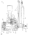
- the pneumatic nailer 10 has a handle 12 which is fixed to a lower housing part 140, which is closed at the top by a housing cap 142.
- the manually operable trigger 14 is pivotally mounted about a pivot axis 16 on the housing of the pneumatic nailer 10 and arranged so that it can be easily operated by a user who holds the pneumatic nailer 10 on the handle 12 with the index finger.
- a button 18 located at the top of the trigger 14 engages a switching pin 20 of a second control valve 22, displaces the switching pin 20 upwardly and thereby controls the second control valve 22. Since this activation of the second control valve 22 is effected directly by the button 18 fixedly arranged on the trigger 14, it takes place independently of the actuation of a touch sensor 24.
- the Aufsetztler 24 is about the mouth 26 of a muzzle tool 28 by a few millimeters down over. If the pneumatic nailer 10 is attached to a workpiece, the Aufsetzmeler 24 is displaced upward against the force of a spring, not shown, until it is flush with the mouth 26 or only slightly beyond the mouth 26.
- the touch sensor 24 is mechanically coupled to a power transmission element 30, which moves with the movement of the Aufsetzmelers 24 upwards.
- the power transmission element 30 is movably guided on the housing of the pneumatic nailer 10 and for this purpose has a slot 32, through which a guide pin 98 is passed.
- the force transmission element 30 moves from the initial position drawn upwards and takes with a fixed to the force transmission element 30 stop pin 34, the free end of a lever 36, the fixed end pivotable about a pivot axis 38 in the interior of the trigger 14th and hinged near its free end.
- the lever 36 is then disposed approximately parallel to a longitudinal direction of the trigger 14 and its upper surface acts as a button 40 which, upon joint actuation of the touch sensor 24 and the trigger 14, displaces a switching pin 42 of a first control valve 44 upwardly and thus drives the first control valve 44 ,
- the mouth tool 28 has a receptacle 46, to which a fastening means is supplied from a magazine 48 in each case. From this position within the receptacle 46, the fastening means - for example, a nail, a pin or a clip - by a driving ram 50, which is connected to a working piston 52 of the pneumatic nailer 10, driven.
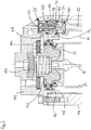
- the working piston 52 is guided in a working cylinder 54. Above the working cylinder 54 and this sealingly closing a main valve 56 is arranged, to the right thereof a pilot valve 58 which controls the main valve 56. Details of these elements and the associated function of the device are based on the enlarged detail of the FIG. 2 explained in more detail.
- the pilot valve 58 is best in the FIG. 2 recognizable. It has a control piston 94, which is guided in a guide sleeve 96. The lower end of the control piston 94 is sealed with a lower O-ring 100 opposite the guide sleeve 96.
- a first control line 82 which is connected to a working volume of the pilot valve 58, vented and the control piston 94 is in the lower position shown. In this position, it is held by the force of a spring 102.
- the spool 94 has a middle O-ring 104 and an upper O-ring 106 in addition to the lower O-ring 100.
- the upper O-ring 106 seals the control piston 94 against the guide sleeve 96 and closes a connection to a vent not shown, which is connected to outside air.
- the middle O-ring 104 is not in seal, so that a main control line 110 is connected via a radial bore 112 in the guide sleeve 96 and the annular gap 70 between the control piston 94 and guide sleeve 96 on the middle O-ring 104 past the housing interior 64.
- the main control line 110 is connected via a not visible in the sectional plane shown connection with the space 72, which opens into the radial bore 112.
- the housing interior 64 is in the initial state of the pneumatic nailer 10 ventilated, that is connected to a compressed air connection, not shown, and standing under operating pressure.
- the main control line 110 is connected to a space 114 above a main valve actuator 116 of the main valve 56, so that the main valve actuator 116 is acted upon by a downward force and thereby the upper edge of the working cylinder 54 by means of an O-ring 118 relative to the housing interior 64th seals.
- the main valve actuator 116 is acted upon by a spring 120 with a force in the direction of the shown, the working cylinder 54 occluding position.
- a drive-in operation is initiated by venting the first control line 82 by displacing the control piston 94 upwardly so that the middle O-ring 104 enters the seal and the upper O-ring 106 moves out of the seal.
- the connection of the main control line 110 is shut off to the housing interior 64 and a connection between the main control line 110 and a vent not shown is made.
- the space 114 above the main valve actuator 116 is vented through the vent and the main valve actuator 116 is displaced upward by the pressure prevailing at its lower, outer annular surface 122 in the housing interior 64 against the force of the spring 120.
- compressed air flows from the housing interior 64 into the working cylinder 54 above the working piston 52 and drives the working piston 52 downwards.
- the driving ram 50 connected to the working piston 52 drives a fastening means.
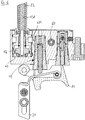
- FIG. 1 Below the pilot valve 58 is a safety valve 124 with a safety valve piston 126 which cooperates with a safety control chamber 62 and a throttle 60. Details of these elements and the associated function of the device are based on the FIGS. 3 to 6 explained in more detail.
- FIG. 3 the manually operated trigger 14 with the lever 36 and the button 18 mounted therein is clearly visible.
- the switching pin 20 of the second control valve 22 is guided in a sleeve 66 of the second control valve 22 which is inserted into the housing and sealed relative thereto.
- a second control line not visible in the sectional planes of the figures, connects a radial bore 68 in the sleeve 66 to the safety control chamber 62.
- An upper O-ring 74 of the second control valve 22 is not in sealing so that the radial bore 68 engages with the Housing interior 64 is connected. Therefore, the safety control chamber 62 is in the in the Fig. 3 vented initial state shown.
- a throttle 60 is connected to the second control line, not shown, which connects the second control line and thus the safety control chamber 62 with outside air. In the initial state, air continuously flows out via the throttle 60, causing an operating noise perceptible to a user.
- the pressure in the safety control chamber 62 acts on the underside of the safety valve piston 126 and holds the safety valve piston 126 against the force of a spring 128 in the upper position shown.
- the safety valve piston 126 is guided in a sleeve 80 and has an upper O-ring 138 which is not in the position shown in seal. Therefore, the first control line 82, within the in the FIG. 3 the spring 128 is arranged, connected via an annular gap 130 and a radial bore 132 in the sleeve 80 with an obliquely arranged, third control line 134.
- the switching pin 42 of the first control valve 44 is guided in a sleeve 76 which has a radial bore 78 connected to the third control line 134.
- An upper O-ring 90 on the valve pin 42 seals against the sleeve 76; a lower O-ring 88 on the valve pin 42 is not in seal. That is why the radial Bore 78 and thus the third control line 134 via an annular gap 84 vented.
- the housing interior 64 is separated from the radial bore 78 by the upper O-ring 90.
- the first control valve 44, the second control valve 22 and the throttle 60 are combined in a common valve block 148.
- FIG. 4 shows the arrangement Fig. 3 immediately after the actuation of the trigger 14.
- the control pin 20 is in an upper position and the second control valve 22 shuts off the connection between the housing interior 64 and the second control line, not shown, because the upper O-ring 74 seals against the sleeve 66 , Thereby, the influx of air into the safety control chamber 62 is shut off and the safety control chamber 62 is vented slowly via the throttle 60.
- the second control valve 22 has two further O-rings 86, which seal the control pin 20 relative to the sleeve 66 in the two end positions of the control pin 20.
- the spaces outside of the two further O-rings 86 are connected to one another via a bypass line 92 running in the interior of the control pin 20.
- the bypass line 92 has two radial bores and an axial bore extending therebetween.
- the ventilation of the first control line 82 also has the effect that air passes through an axial bore 136 and a radial bore 144 in the safety valve piston 126 to the inside of an O-ring 146 which is inserted into a circumferential groove of the control piston 126 and a Forming check valve that leads into the safety control chamber 62.
- the check valve opens so that the safety control chamber 62 is vented due to the driving operation. The time within which further driving operations are possible by means of contact triggering begins again to run.
- FIG. 6 shows a locked state of the Druck Kunststoffnaglers 10, starting from the FIG. 4 , so when pressed trigger 14, automatically after a certain period of inactivity results, for example, after about 4 s.
- the pressure in the safety control chamber 62 has dropped below the predetermined pressure threshold due to the air escaping via the throttle 60, so that the safety valve piston 126 has moved downward due to the force of the spring 128, ie the safety valve 124 is in a blocking position in which the connection between the third control line 134 and the first control line 82 is shut off.
- the touch sensor 24 is actuated and the first control valve 44 is activated, the ventilation of the third control line 134 remains without consequences.
- a drive-in process can only be triggered again when the pressure in the safety control chamber 62 is restored. This is possible at any time by briefly releasing the trigger 14.
Description
Die Erfindung betrifft einen Druckluftnagler mit einem Arbeitskolben, der mit einem Eintreibstößel zum Eintreiben eines Befestigungsmittels verbunden ist und beim Auslösen eines Eintreibvorgangs mit Druckluft beaufschlagt wird, einer Auslöseeinrichtung, die einen handbetätigbaren Auslöser und einen Aufsetzfühler aufweist, wobei eine gemeinsame Betätigung von Auslöser und Aufsetzfühler ein erstes Steuerventil ansteuert und einen Eintreibvorgang auslöst, falls der Druck in einer Sicherheitssteuerkammer oberhalb einer vorgegebenen Druckschwelle liegt, und einem zweiten Steuerventil, das bei einer Betätigung des Auslösers unabhängig von einer Betätigung des Aufsetzfühlers angesteuert wird.The invention relates to a pneumatic nailer with a working piston, which is connected to a driving ram for driving a fastener and is applied to trigger a Eintreibvorgangs with compressed air, a triggering device having a manually actuable trigger and a touch sensor, wherein a joint actuation of trigger and Aufsetzfühler a controls a first control valve and triggers a driving operation, if the pressure in a safety control chamber is above a predetermined pressure threshold, and a second control valve, which is actuated upon actuation of the trigger independently of an actuation of the Aufsetzfühlers.
Bei dem Aufsetzfühler handelt es sich um ein mechanisches Bauteil, das in der Regel von einer Feder in einer über ein Mündungswerkzeug des Druckluftnaglers überstehenden Position gehalten wird. Wird der Druckluftnager an ein Werkstück angesetzt, wird der Aufsetzfühler gegen die Kraft der Feder verlagert, bis das Mündungswerkzeug an dem Werkstück anliegt oder fast anliegt. Nur bei derart betätigtem Aufsetzfühler kann ein Eintreibvorgang ausgelöst werden. Dadurch bieten die bekannten Druckluftnagler gegenüber Geräten ohne Aufsetzfühler eine erheblich verbesserte Sicherheit gegen unbeabsichtigte Auslösungen.The Aufsetzfühler is a mechanical component, which is usually held by a spring in a protruding over a neck tool of Druckluftnaglers position. If the compressed air bearing is attached to a workpiece, the touch sensor is displaced against the force of the spring until the muzzle tool rests against the workpiece or almost rests. Only with such actuated Aufsetzfühler a driving operation can be triggered. As a result, the known compressed air nailers offer a significantly improved security against unintentional release compared to devices without Aufsetzfühler.
Druckluftnagler mit einer Auslöseeinrichtung der beschriebenen Art können in zwei unterschiedlichen Betriebsarten eingesetzt werden. Bei der sogenannten Einzelauslösung wird der Druckluftnagler zunächst an ein Werkstück angesetzt und dadurch der Aufsetzfühler betätigt. Nachfolgend wird von Hand der Auslöser betätigt und dadurch ein einzelner Eintreibvorgang ausgelöst.Pneumatic nailer with a triggering device of the type described can be used in two different modes. In the so-called single release the pneumatic nailer is first attached to a workpiece and thereby actuated the landing sensor. Subsequently, the trigger is actuated by hand, thereby triggering a single drive.
Bei der sogenannten Kontaktauslösung, auch als "Touchen" bezeichnet, hält der Benutzer den Auslöser bereits gedrückt, während er den Druckluftnagler an das Werkstück ansetzt. Beim Ansetzen an das Werkstück wird der Aufsetzfühler betätigt und dadurch ein Eintreibvorgang auslöst. Der Druckluftnagler kann wiederholt in schneller Folge angesetzt werden, was ein sehr schnelles Arbeiten ermöglicht, insbesondere wenn für eine ausreichende Befestigung viele Befestigungsmittel eingetrieben werden müssen, an deren Positioniergenauigkeit nur geringe Anforderungen gestellt werden.In the so-called contact release, also referred to as touch, the user already holds the trigger while pressing the pneumatic nailer against the workpiece. When attaching to the workpiece of the touch sensor is actuated and thereby initiates a drive-in process. The compressed air nailer can be repeatedly set in rapid succession, which allows a very fast working, especially if many fasteners must be driven for a sufficient attachment to the positioning accuracy only small demands are made.
In bestimmten Situationen geht von dem Kontaktauslöseverfahren jedoch ein erhöhtes Verletzungsrisiko aus. Hält der Benutzer den handbetätigten Auslöser beispielsweise nicht nur dann gedrückt, wenn er den Druckluftnagler auf ein und demselben Werkstück in einem Abstand von einigen Zentimetern vom zuletzt eingetriebenen Befestigungsmittel aufsetzen will, sondern auch dann, wenn er zu einem anderen, entfernt angeordnetem Werkstück wechselt, kann bei einer unbeabsichtigten Berührung eines Gegenstands oder Körperteils mit dem Aufsetzfühler ein Eintreibvorgang ausgelöst werden. Beispielsweise kann es zu Unfällen kommen, wenn ein Benutzer (unter Missachtung wichtiger Sicherheitsvorschriften) mit dem Druckluftnagler auf eine Leiter steigt, dabei den Auslöser gedrückt hält und versehentlich mit dem Aufsetzfühler sein Bein streift.In certain situations, however, the contact triggering procedure entails an increased risk of injury. For example, not only does the user depress the hand-operated trigger when he wants to place the pneumatic nailer on one and the same workpiece a few centimeters from the last driven fastener, but also when changing to another remotely located workpiece in an accidental contact of an object or body part with the Aufsetzfühler a driving operation are triggered. For example, accidents can occur when a user (in disregard of important safety regulations) climbs a ladder with the pneumatic nailer while holding the trigger and accidentally brushing his leg with the touch probe.
Der aus der Druckschrift
Davon ausgehend ist es die Aufgabe der Erfindung, einen Druckluftnagler mit einem verbesserten Sicherheitsmechanismus zur Verfügung zu stellen.On this basis, it is the object of the invention to provide a pneumatic nailer with an improved safety mechanism.
Diese Aufgabe wird gelöst durch den Druckluftnagler mit den Merkmalen des Anspruchs 1. Vorteilhafte Ausgestaltungen sind in den sich anschließenden Unteransprüchen angegeben.This object is achieved by the pneumatic nailer with the features of claim 1. Advantageous embodiments are specified in the subsequent subclaims.
Der Druckluftnagler hat
- einen Arbeitskolben, der mit einem Eintreibstößel zum Eintreiben eines Befestigungsmittels verbunden ist und beim Auslösen eines Eintreibvorgangs mit Druckluft beaufschlagt wird,
- eine Auslöseeinrichtung, die einen handbetätigbaren Auslöser und einen Aufsetzfühler aufweist, wobei eine gemeinsame Betätigung von Auslöser und Aufsetzfühler ein erstes Steuerventil ansteuert und einen Eintreibvorgang auslöst, falls der Druck in einer Sicherheitssteuerkammer oberhalb einer vorgegebenen Druckschwelle liegt,
- ein zweites Steuerventil, das bei einer Betätigung des Auslösers unabhängig von einer Betätigung des Aufsetzfühlers angesteuert wird,
- wobei die Sicherheitssteuerkammer unabhängig von der Stellung des zweiten Steuerventils fortlaufend über eine Drossel entlüftet und bei Ansteuerung des zweiten Steuerventils von einem unter Druck stehenden Gehäuseinnenraum getrennt wird.
- a working piston, which is connected to a driving ram for driving in a fastening means and is subjected to the triggering of a driving operation with compressed air,
- a triggering device having a hand-operated trigger and a touchdown sensor, wherein a joint actuation of the trigger and Aufsetzfühler drives a first control valve and triggers a drive-in operation, if the pressure in a safety control chamber is above a predetermined pressure threshold,
- a second control valve, which is actuated upon actuation of the trigger independently of an actuation of the Aufsetzfühlers,
- wherein the safety control chamber is continuously vented independently of the position of the second control valve via a throttle and is separated when driving the second control valve from a pressurized housing interior.
Der Druckluftnager wird zum Eintreiben von Befestigungsmitteln wie Nägeln, Stiften oder Klammern verwendet. Hierzu kann der Druckluftnagler ein Magazin für die Befestigungsmittel aufweisen, aus dem jeweils ein Befestigungsmittel einer Aufnahme eines Mündungswerkzeugs des Druckluftnaglers zugeführt wird.The pneumatic rodger is used to drive fasteners such as nails, pins or staples. For this purpose, the pneumatic nailer can have a magazine for the fastening means, from which in each case a fastening means is supplied to a receptacle of a necking tool of the pneumatic nailer.
Sowohl der Antrieb als auch die Steuerung des Druckluftnaglers können vollständig pneumatisch erfolgen, eine Versorgung mit elektrischer Energie ist daher nicht erforderlich. Mit "Entlüften" ist stets gemeint, dass eine Verbindung zu einem drucklosen Raum, insbesondere zur Außenluft, hergestellt wird. Mit "Belüften" ist stets gemeint, dass eine Verbindung zu einem Druckluft führenden Raum hergestellt wird.Both the drive and the control of the pneumatic nailer can be done completely pneumatically, a supply of electrical energy is therefore not required. By "venting" is always meant that a connection to a non-pressurized space, in particular to the outside air, is produced. By "venting" is always meant that a connection is made to a compressed air leading room.
Beim Auslösen eines Eintreibvorgangs wird ein Arbeitskolben des Druckluftnaglers mit Druckluft beaufschlagt. Dabei treibt der Arbeitskolben einen Eintreibstößel an, der mit dem Arbeitskolben verbunden ist. Der Eintreibstößel trifft auf ein hinteres Ende des Befestigungsmittels in der Aufnahme des Mündungswerkzeugs auf und treibt das Befestigungsmittel in das Werkstück ein.When initiating a driving operation, a working piston of the pneumatic nailer is pressurized with compressed air. In this case, the working piston drives a Eintreibstößel, which is connected to the working piston. The drive ram strikes a rear end of the fastener in the receptacle of the muzzle tool and drives the fastener into the workpiece.
Die Auslöseeinrichtung hat einen handbetätigbaren Auslöser, beispielsweise in Form eines Kipp- oder Schiebetasters, und einen Aufsetzfühler. Bei dem Aufsetzfühler kann es sich um ein mechanisches Bauelement handeln, das über das vordere Ende des Mündungswerkzeugs übersteht und von einer Feder in dieser Stellung gehalten wird, bis der Druckluftnagler an ein Werkstück angesetzt wird. Dann wird der Aufsetzfühler entgegen der Richtung der Federkraft und entgegen der Eintreibrichtung verlagert. Erfolgt diese Betätigung des Aufsetzfühlers gemeinsam mit einer Betätigung des Auslösers, wird ein erstes Steuerventil angesteuert, wodurch ein Eintreibvorgang ausgelöst werden kann.The triggering device has a hand-operated trigger, for example in the form of a tilt or push button, and a touch sensor. The touch sensor may be a mechanical component that projects beyond the front end of the muzzle tool and is held in this position by a spring until the pneumatic nailer is attached to a workpiece. Then the Aufsetzfühler is displaced against the direction of the spring force and against the driving direction. If this actuation of the touch probe together with an actuation of the trigger, a first control valve is actuated, whereby a driving operation can be triggered.
Bei einer gemeinsamen Betätigung von Auslöser und Aufsetzfühler wird das erste Steuerventil angesteuert. Wird nur entweder der handbetätigbare Auslöser oder der Aufsetzfühler betätigt, wird das erste Steuerventil nicht angesteuert. Für eine gemeinsame Betätigung von Auslöser und Aufsetzfühler reicht es aus, wenn sowohl der Auslöser als auch der Aufsetzfühler zu einem bestimmten Zeitpunkt beide zugleich im betätigten Zustand sind. Dies kann einerseits durch eine gleichzeitige Betätigung erreicht werden, aber auch in einer beliebigen Reihenfolge. Beispielsweise kann, wie es für eine Einzelauslösung typisch ist, zunächst der Aufsetzfühler betätigt werden und anschließend der handbetätigbare Auslöser. Im Kontaktauslösebetrieb kann hingegen zuerst der handbetätigbare Auslöser und dann der Aufsetzfühler betätigt werden.With a common actuation of trigger and Aufsetzfühler the first control valve is activated. If only one of the manually actuable release and the touch sensor is actuated, the first control valve will not be actuated. For a joint actuation of trigger and Aufsetzfühler it is sufficient if both the trigger and the touch sensor at a certain time both at the same time in the actuated state. This can be achieved on the one hand by a simultaneous operation, but also in any order. For example can, as is typical for a single triggering, first the touch sensor be actuated and then the hand-actuated trigger. In contact tripping operation, however, the hand-actuated trigger and then the touch sensor can be operated first.
Die Ansteuerung des ersten Steuerventils kann durch eine mechanische Kopplung des handbetätigbaren Auslösers und des Aufsetzfühlers erreicht werden. Beispielsweise kann ein Steuerstift des ersten Steuerventils erst bei einer gemeinsamen Betätigung von Auslöser und Aufsetzfühler verlagert und das erste Steuerventil dadurch angesteuert werden.The control of the first control valve can be achieved by a mechanical coupling of the manually operated release and the Aufsetzfühlers. For example, a control pin of the first control valve can only be displaced when the trigger and the touch sensor are actuated together, and the first control valve can thereby be activated.
Die Ansteuerung des ersten Steuerventils löst einen Eintreibvorgang aus, falls der Druck in der Sicherheitssteuerkammer oberhalb einer vorgegebenen Druckschwelle liegt. Anderenfalls wird beim Ansteuern des ersten Steuerventils kein Eintreibvorgang ausgelöst.The actuation of the first control valve triggers a drive-in operation if the pressure in the safety control chamber is above a predetermined pressure threshold. Otherwise, when driving the first control valve no drive-in process is triggered.
Das zweite Steuerventil wird bei einer Betätigung des handbetätigbaren Auslösers unabhängig von einer Betätigung des Aufsetzfühlers angesteuert. Das zweite Steuerventil wird also bei jeder Betätigung des Auslösers angesteuert. Hierzu kann beispielsweise ein Steuerstift des zweiten Steuerventils so angeordnet sein, dass er bei jeder Betätigung des Auslösers aus seiner Ruhestellung verlagert wird.The second control valve is actuated upon actuation of the manually operable trigger independently of an actuation of the Aufsetzfühlers. The second control valve is thus activated with each actuation of the trigger. For this purpose, for example, a control pin of the second control valve may be arranged so that it is displaced from its rest position with each actuation of the trigger.
Bei der Erfindung wird die Sicherheitssteuerkammer unabhängig von der Stellung des zweiten Steuerventils fortlaufend über eine Drossel entlüftet und bei Ansteuerung des zweiten Steuerventils von einem unter Druck stehenden Gehäuseinnenraum getrennt. In einem Ausgangszustand des Druckluftnaglers ist die Sicherheitssteuerkammer mit dem unter Druck stehenden Gehäuseinnenraum verbunden. Mit "Ausgangszustand" ist stets ein Zustand gemeint, in dem der Druckluftnagler an eine Druckluftversorgung angeschlossen ist und weder der Aufsetzfühler noch der Auslöser betätigt sind. Gleichzeitig wird die Sicherheitssteuerkammer fortlaufend über die Drossel entlüftet. Wird die Verbindung zwischen der Sicherheitssteuerkammer und dem unter Druck stehenden Gehäuseinnenraum durch Ansteuern des zweiten Steuerventils getrennt, wird der über die Drossel entweichende Luftstrom nicht mehr durch aus dem Gehäuseinnenraum in die Sicherheitssteuerkammer nachströmende Luft kompensiert und der Druck in der Sicherheitssteuerkammer fällt innerhalb einer bestimmten Zeit unter die vorgegebene Druckschwelle, sodass weitere Auslösungen nicht mehr möglich sind.In the invention, the safety control chamber is vented independently of the position of the second control valve continuously via a throttle and separated when controlling the second control valve of a pressurized housing interior. In an initial state of the pneumatic nailer, the safety control chamber is connected to the pressurized housing interior. By "initial state" is always meant a state in which the pneumatic nailer is connected to a compressed air supply and neither the touch sensor nor the trigger are actuated. At the same time, the safety control chamber becomes continuous vented via the throttle. If the connection between the safety control chamber and the pressurized housing interior separated by driving the second control valve, the air flow escaping through the throttle is no longer compensated by flowing from the housing interior into the safety control chamber air and the pressure in the safety control chamber falls within a certain time the predetermined pressure threshold, so that further triggering is no longer possible.
Der auf den ersten Blick als Nachteil erscheinende, fortlaufende Luftverlust über die Drossel hat sich in der Praxis als besonderer Vorteil herausgestellt, denn er fällt hinsichtlich des Druckluftverbrauchs nicht ins Gewicht und verursacht ein Betriebsgeräusch. Hierzu kann die Drossel bzw. eine die Drossel mit Außenluft verbindende Leitung insbesondere so angeordnet und ein über die Drossel entweichender Luftstrom so bemessen sein, dass die über die Drossel entweichende Luft ein für einen Benutzer wahrnehmbares Betriebsgeräusch verursacht.The seemingly at a first disadvantage, continuous loss of air through the throttle has been found in practice to be a particular advantage, because it does not fall in terms of compressed air consumption in the weight and causes an operating noise. For this purpose, the throttle or a line connecting the throttle with the outside air can be arranged in particular and a flow of air which escapes via the throttle can be dimensioned so that the air escaping via the throttle causes a perceptible operating noise for a user.
Dieses Betriebsgeräusch zeigt ein einwandfreies Funktionieren der Sicherheitseinrichtung und die Schussbereitschaft des Geräts an: Kommt es zu einer Fehlfunktion, etwa bei einer Verschmutzung der Drossel, verändert sich oder verstummt das Betriebsgeräusch. Verstummt das Betriebsgeräusch bei betätigtem Auslöser infolge des Druckverlusts in der Sicherheitssteuerkammer, zeigt dies einem Benutzer an, dass weitere Eintreibvorgänge erst ausgelöst werden können, nachdem der Druck in der Sicherheitssteuerkammer durch Loslassen des Auslösers wiederhergestellt ist.This operating noise indicates the correct functioning of the safety device and the ready-to-fire status of the device: If a malfunction occurs, for example if the throttle is soiled, the operating noise will change or become dull. If the operating sound is silenced when the trigger is depressed as a result of the pressure loss in the safety control chamber, this indicates to a user that further drive-in operations can not be triggered until the pressure in the safety control chamber has been restored by releasing the trigger.
In einer Ausgestaltung wird die Sicherheitssteuerkammer bei nicht betätigtem Auslöser über das zweite Steuerventil belüftet. Hierzu wird über das zweite Steuerventil eine unmittelbare Verbindung zwischen der Sicherheitssteuerkammer und einem unter Druck stehenden Gehäuseinnenraum hergestellt, was zu einer instantanen Belüftung der Sicherheitssteuerkammer führt. Der Druckluftnagler befindet sich daher nach dem Loslassen des Auslösers innerhalb kürzester Zeit wieder in einem schussbereiten Ausgangszustand.In one embodiment, the safety control chamber is vented when the trigger is not actuated via the second control valve. For this purpose, a direct connection between the safety control chamber and a housing interior under pressure is produced via the second control valve, which leads to an instantaneous ventilation of the safety control chamber. The pneumatic nailer is located Therefore, after releasing the trigger within a very short time again in a ready shot initial state.
In einer Ausgestaltung ist die Drossel an eine Leitung angeschlossen, die das zweite Steuerventil mit der Sicherheitssteuerkammer verbindet. Grundsätzlich kann sich die Drossel in einer beliebigen Verbindung zwischen der Sicherheitssteuerkammer und Außenluft befinden. Die Anordnung an der zur Belüftung der Sicherheitssteuerkammer über das zweite Steuerventil vorgesehenen Leitung ermöglicht eine besonders einfache, kompakte Konstruktion.In one embodiment, the throttle is connected to a line which connects the second control valve with the safety control chamber. Basically, the throttle may be in any connection between the safety control chamber and outside air. The arrangement of the provided for the ventilation of the safety control chamber via the second control valve line allows a particularly simple, compact design.
In einer Ausgestaltung sind das erste Steuerventil, das zweite Steuerventil und die Drossel in einem Ventilblock zusammengefasst. Auch diese Maßnahme dient einer einfachen und kompakten Konstruktion.In one embodiment, the first control valve, the second control valve and the throttle are combined in a valve block. This measure also serves a simple and compact construction.
In einer Ausgestaltung wirkt der Druck in der Sicherheitssteuerkammer auf einen Sicherheitsventilkolben eines Sicherheitsventils, das eine Leitung absperrt, die bei Ansteuerung des ersten Steuerventils belüftet oder entlüftet wird. Abhängig vom Druck in der Sicherheitssteuerkammer wird also eine zum Auslösen eines Eintreibvorgangs dienende Leitung abgesperrt, so dass ein Auslösen verhindert wird. Hierzu kann die Sicherheitssteuerkammer über eine Leitung mit einem Arbeitsvolumen des Sicherheitsventils verbunden sein oder sie kann dieses Arbeitsvolumen bilden. Der Druck in der Sicherheitssteuerkammer kann den Sicherheitsventilkolben insbesondere in eine Richtung pressen, die einer Offenstellung des Sicherheitsventils entspricht.In one embodiment, the pressure in the safety control chamber acts on a safety valve piston of a safety valve which shuts off a line which is vented or vented when the first control valve is actuated. Depending on the pressure in the safety control chamber so serving to trigger a driving operation line is shut off, so that triggering is prevented. For this purpose, the safety control chamber can be connected via a line with a working volume of the safety valve or it can form this working volume. The pressure in the safety control chamber can in particular press the safety valve piston in one direction, which corresponds to an open position of the safety valve.
In einer Ausgestaltung spannt eine Feder den Sicherheitsventilkolben gegen den Druck in der Sicherheitssteuerkammer vor. Die Stellung des Sicherheitsventils ergibt sich daher aus dem Zusammenspiel der Federkraft und der von dem Druck in der Sicherheitssteuerkammer auf den Sicherheitsventilkolben ausgeübten Kraft. Es kann daher durch Abstimmen der Feder auf den effektiven Querschnitt des Sicherheitsventilkolbens exakt vorgeben werden, bis zu welchem Druck in der Sicherheitssteuerkammer das Sicherheitsventil in seiner Offenstellung verbleibt.In one embodiment, a spring biases the safety valve piston against the pressure in the safety control chamber. The position of the safety valve therefore results from the interaction of the spring force and the pressure exerted by the pressure in the safety control chamber on the safety valve piston force. It can therefore be adjusted by tuning the spring to the effective cross section of the safety valve piston exactly specify up to what pressure in the safety control chamber the safety valve remains in its open position.
In einer Ausgestaltung weist der Druckluftnagler ein Vorsteuerventil mit einem Steuerkolben auf, wobei der Steuerkolben und der Sicherheitsventilkolben entlang einer gemeinsamen Längsachse angeordnet sind. Das Vorsteuerventil dient zum Steuern eines Hauptventils des Druckluftnaglers, über das der Arbeitskolben belüftet wird. Die genannte Anordnung von Steuerkolben und Sicherheitsventilkolben ermöglicht einen besonders einfach zu fertigenden, kompakten Aufbau des Druckluftnaglers.In one embodiment, the pneumatic nailer has a pilot valve with a control piston, wherein the control piston and the safety valve piston are arranged along a common longitudinal axis. The pilot valve is used to control a main valve of the pneumatic nailer, via which the working piston is ventilated. Said arrangement of control piston and safety valve piston allows a particularly easy to manufacture, compact design of the pneumatic nailer.
In einer Ausgestaltung sind der Steuerkolben und der Sicherheitsventilkolben seitlich von dem Arbeitszylinder angeordnet. Insbesondere kann die gemeinsame Achse von Steuerkolben und Sicherheitsventilkolben parallel zu einer Längsachse des Arbeitszylinders ausgerichtet sein. Auch diese Merkmale begünstigen eine einfache Fertigung und einen kompakten Aufbau des Druckluftnaglers.In one embodiment, the control piston and the safety valve piston are arranged laterally of the working cylinder. In particular, the common axis of the control piston and safety valve piston can be aligned parallel to a longitudinal axis of the working cylinder. These features also favor a simple production and a compact design of the pneumatic nailer.
In einer Ausgestaltung ist ein Öffnungsquerschnitt der Drossel so bemessen, dass beim Betrieb des Druckluftnaglers mit einem dafür vorgesehenen Betriebsdruck der Druck in der Sicherheitssteuerkammer die vorgegebene Druckschwelle in einem Zeitraum von 0,1 s bis 10 s nach Ansteuerung des zweiten Steuerventils unterschreitet. Insbesondere kann die Druckschwelle in einem Zeitraum zwischen 1 s und 5 s nach Ansteuerung des zweiten Steuerventils unterschritten werden, zum Beispiel nach ungefähr 4 s. Der Öffnungsquerschnitt der Drossel kann einstellbar sein, sodass der Zeitraum individuell reguliert werden kann. Bevorzugt erfolgt diese Regulierung nur einmalig durch den Hersteller des Druckluftnaglers und ist nur durch unzulässige Manipulation durch einen Anwender veränderbar. In jedem Fall wird der Druckluftnagler rechtzeitig gesperrt, um in vielen typischen Anwendungssituationen einen Eintreibvorgang in Folge einer unbeabsichtigten Betätigung des Aufsetzfühlers zu verhindern.In one embodiment, an opening cross-section of the throttle is dimensioned such that during operation of the pneumatic nailer with a designated operating pressure of the pressure in the safety control chamber falls below the predetermined pressure threshold in a period of 0.1 s to 10 s after activation of the second control valve. In particular, the pressure threshold can be exceeded in a period between 1 s and 5 s after activation of the second control valve, for example after approximately 4 s. The opening cross-section of the throttle can be adjustable, so that the period can be individually regulated. Preferably, this regulation takes place only once by the manufacturer of the pneumatic nailer and can only be changed by impermissible manipulation by a user. In any case, the pneumatic nailer is locked in time to prevent in many typical application situations a driving operation as a result of unintentional actuation of the Aufsetzfühlers.
In einer Ausgestaltung weist der Druckluftnagler ein Rückschlagventil auf, über das die Sicherheitssteuerkammer beim Auslösen eines Eintreibvorgangs belüftet wird. Dadurch wird beim Auslösen eines Eintreibvorgangs hinsichtlich des Drucks in der Sicherheitssteuerkammer der Ausgangszustand wiederhergestellt. Dies kann sehr schnell geschehen. Wird nach dem Eintreibvorgang der Auslöser weiterhin gedrückt gehalten, nähert sich der Druck in der Sicherheitssteuerkammer in der zuvor geschilderten Weise wieder der Druckschwelle, welche nach dem vorgegebenen Zeitraum unterschritten wird. Bis dahin ist jederzeit eine weitere Auslösung durch Betätigen des Aufsetzfühlers möglich, sodass der Druckluftnagler ohne Beschränkung für schnell aufeinanderfolgende Eintreibvorgängen im Kontaktauslöseverfahren geeignet ist.In one embodiment, the pneumatic nailer on a check valve, via which the safety control chamber is vented when triggering a Eintreibvorgangs. Thereby, the initial state is restored upon initiation of a driving operation with respect to the pressure in the safety control chamber. This can happen very fast. If, after the drive-in operation, the trigger is still kept pressed, the pressure in the safety control chamber approaches in the previously described manner again the pressure threshold, which is undershot after the predetermined period of time. Until then, a further release by pressing the Aufsetzfühlers is possible at any time, so that the Druckluftnagler is suitable without restriction for fast successive Eintreibvorgängen in the contact triggering process.
Nachfolgend wird die Erfindung anhand eines in Figuren dargestellten Ausführungsbeispiels näher erläutert. Es zeigen:
- Fig. 1
- einen erfindungsgemäßen Druckluftnagler in einer teilweise geschnittenen Darstellung,
- Fig. 2
- eine vergrößerte Ansicht eines Ausschnitts mit Hauptventil und Vorsteuerventil aus
Figur 1 , - Fign. 3 bis 6
- vergrößerte Darstellungen ausgewählter Elemente aus
Figur 1 in unterschiedlichen Betriebszuständen.
- Fig. 1
- a compressed air nailer according to the invention in a partially sectioned illustration,
- Fig. 2
- an enlarged view of a section with main valve and pilot valve off
FIG. 1 . - FIGS. 3 to 6
- enlarged views of selected elements
FIG. 1 in different operating states.
Zunächst werden anhand der
Der handbetätigbare Auslöser 14 ist um eine Schwenkachse 16 schwenkbar am Gehäuse des Druckluftnaglers 10 gelagert und so angeordnet, dass er von einem Benutzer, der den Druckluftnagler 10 am Handgriff 12 hält, bequem mit dem Zeigefinger betätigt werden kann. Bei dieser Betätigung gelangt eine an der Oberseite des Auslösers 14 angeordnete Schaltfläche 18 in Anlage mit einem Schaltstift 20 eines zweiten Steuerventils 22, verlagert den Schaltstift 20 nach oben und steuert dadurch das zweite Steuerventil 22 an. Da diese Ansteuerung des zweiten Steuerventils 22 unmittelbar von der fest am Auslöser 14 angeordneten Schaltfläche 18 bewirkt wird, erfolgt sie unabhängig von der Betätigung eines Aufsetzfühlers 24.The manually
Der Aufsetzfühler 24 steht über die Mündung 26 eines Mündungswerkzeugs 28 um einige Millimeter nach unten über. Wird der Druckluftnagler 10 an ein Werkstück angesetzt, wird der Aufsetzfühler 24 gegen die Kraft einer nicht gezeigten Feder nach oben verlagert, bis er bündig mit der Mündung 26 abschließt oder nur noch geringfügig über die Mündung 26 übersteht. Der Aufsetzfühler 24 ist mechanisch gekoppelt mit einem Kraftübertragungselement 30, das sich bei der Bewegung des Aufsetzfühlers 24 nach oben mitbewegt. Das Kraftübertragungselement 30 ist am Gehäuse des Druckluftnaglers 10 beweglich geführt und weist hierzu ein Langloch 32 auf, durch das ein Führungsstift 98 hindurchgeführt ist.The
Bei einer Betätigung des Aufsetzfühlers 24 verlagert sich das Kraftübertragungselement 30 aus der gezeichneten Ausgangsstellung nach oben und nimmt dabei mit einem an dem Kraftübertragungselement 30 befestigten Anschlagstift 34 das freie Ende eines Hebels 36 mit, dessen festes Ende um eine Schwenkachse 38 schwenkbar im Inneren des Auslösers 14 und nahe dessen freiem Ende angelenkt ist. Der Hebel 36 ist dann annähernd parallel zu einer Längsrichtung des Auslösers 14 angeordnet und seine Oberseite wirkt als Schaltfläche 40, die bei gemeinsamer Betätigung des Aufsetzfühlers 24 und des Auslösers 14 einen Schaltstift 42 eines ersten Steuerventils 44 nach oben verlagert und das erste Steuerventil 44 somit ansteuert.Upon actuation of the
Das Mündungswerkzeug 28 weist eine Aufnahme 46 auf, der jeweils ein Befestigungsmittel aus einem Magazin 48 zugeführt wird. Aus dieser Position innerhalb der Aufnahme 46 wird das Befestigungsmittel - beispielsweise ein Nagel, ein Stift oder eine Klammer - von einem Eintreibstößel 50, der mit einem Arbeitskolben 52 des Druckluftnaglers 10 verbunden ist, eingetrieben. Hierzu ist der Arbeitskolben 52 in einem Arbeitszylinder 54 geführt. Oberhalb des Arbeitszylinders 54 und diesen dichtend verschließend ist ein Hauptventil 56 angeordnet, rechts davon ein Vorsteuerventil 58, das das Hauptventil 56 steuert. Einzelheiten dieser Elemente sowie die damit zusammenhängende Funktion des Gerätes werden anhand der Ausschnittsvergrößerung der
Das Vorsteuerventil 58 ist am besten in der
Der Steuerkolben 94 weist zusätzlich zu dem unteren O-Ring 100 einen mittleren O-Ring 104 und einen oberen O-Ring 106 auf. In der gezeigten, unteren Stellung des Steuerkolbens 94 dichtet der obere O-Ring 106 den Steuerkolben 94 gegenüber der Führungshülse 96 ab und verschließt eine Verbindung zu einer nicht gezeigten Entlüftungsöffnung, die mit Außenluft verbunden ist. Der mittlere O-Ring 104 befindet sich nicht in Dichtung, sodass eine Hauptsteuerleitung 110 über eine radiale Bohrung 112 in der Führungshülse 96 und den Ringspalt 70 zwischen Steuerkolben 94 und Führungshülse 96 am mittleren O-Ring 104 vorbei mit dem Gehäuseinnenraum 64 verbunden ist. Die Hauptsteuerleitung 110 ist über eine in der gezeigten Schnittebene nicht sichtbare Verbindung mit dem Raum 72, der in die radiale Bohrung 112 mündet, verbunden. Der Gehäuseinnenraum 64 ist im Ausgangszustand des Druckluftnaglers 10 belüftet, d. h. mit einem nicht gezeigten Druckluftanschluss verbunden und unter Betriebsdruck stehend.The
Die Hauptsteuerleitung 110 ist mit einem Raum 114 oberhalb eines Hauptventil-Stellglieds 116 des Hauptventils 56 verbunden, sodass das Hauptventil-Stellglied 116 mit einer Kraft nach unten beaufschlagt wird und dadurch den oberen Rand des Arbeitszylinders 54 mittels eines O-Rings 118 gegenüber dem Gehäuseinnenraum 64 abdichtet. Zusätzlich wird das Hauptventil-Stellglied 116 von einer Feder 120 mit einer Kraft in Richtung der gezeigten, den Arbeitszylinder 54 verschließenden Stellung beaufschlagt.The
Ein Eintreibvorgang wird durch Belüften der ersten Steuerleitung 82 ausgelöst, indem der Steuerkolben 94 nach oben verlagert wird, sodass der mittlere O-Ring 104 in Dichtung gelangt und der obere O-Ring 106 aus der Dichtung fährt. Dadurch wird die Verbindung der Hauptsteuerleitung 110 zum Gehäuseinnenraum 64 abgesperrt und eine Verbindung zwischen Hauptsteuerleitung 110 und einer nicht gezeigten Entlüftungsöffnung wird hergestellt. Der Raum 114 oberhalb des Hauptventil-Stellglieds 116 wird über die Entlüftungsöffnung entlüftet und das Hauptventil-Stellglied 116 wird durch den an seiner unteren, äußeren Ringfläche 122 anstehenden, im Gehäuseinnenraum 64 herrschenden Druck gegen die Kraft der Feder 120 nach oben verlagert. Dadurch strömt Druckluft aus dem Gehäuseinnenraum 64 in den Arbeitszylinder 54 oberhalb des Arbeitskolbens 52 und treibt den Arbeitskolben 52 nach unten. Bei dieser Abwärtsbewegung treibt der mit dem Arbeitskolben 52 verbundene Eintreibstößel 50 ein Befestigungsmittel ein.A drive-in operation is initiated by venting the
In der
In der
Außerdem ist an die nicht gezeigte, zweite Steuerleitung eine Drossel 60 angeschlossen, die die zweite Steuerleitung und damit die Sicherheitssteuerkammer 62 mit Außenluft verbindet. Im Ausgangszustand strömt fortlaufend Luft über die Drossel 60 nach außen, was ein für einen Benutzer wahrnehmbares Betriebsgeräusch verursacht.In addition, a
Der Druck in der Sicherheitssteuerkammer 62 wirkt auf die Unterseite des Sicherheitsventilkolbens 126 und hält den Sicherheitsventilkolben 126 gegen die Kraft einer Feder 128 in der gezeigten, oberen Stellung. Der Sicherheitsventilkolben 126 ist in einer Hülse 80 geführt und weist einen oberen O-Ring 138 auf, der sich in der gezeigten Stellung nicht in Dichtung befindet. Darum ist die erste Steuerleitung 82, innerhalb der in der
Der Schaltstift 42 des ersten Steuerventils 44 ist in einer Hülse 76 geführt, die eine mit der dritten Steuerleitung 134 verbundene, radiale Bohrung 78 aufweist. Ein oberer O-Ring 90 am Ventilstift 42 dichtet gegenüber der Hülse 76 ab; ein unterer O-Ring 88 am Ventilstift 42 befindet sich nicht in Dichtung. Darum ist die radiale Bohrung 78 und damit die dritte Steuerleitung 134 über einen Ringspalt 84 entlüftet. In der gezeigten Ausgangsstellung ist zugleich der Gehäuseinnenraum 64 durch den oberen O-Ring 90 von der radialen Bohrung 78 getrennt.The switching
Das erste Steuerventil 44, das zweite Steuerventil 22 und die Drossel 60 sind in einem gemeinsamen Ventilblock 148 zusammengefasst.The
Als zusätzliche Sicherheitsmaßnahme weist das zweite Steuerventil 22 zwei weitere O-Ringe 86 auf, die in den beiden Endstellungen des Steuerstifts 20 den Steuerstift 20 gegenüber der Hülse 66 abdichten. Die Räume außerhalb der beiden weiteren O-Ringe 86 sind über eine im Inneren des Steuerstifts 20 verlaufende Bypass-Leitung 92 miteinander verbunden. Die Bypass-Leitung 92 weist zwei radiale Bohrungen und eine dazwischen verlaufende, axiale Bohrung auf. Die Wirkung dieser Sicherheitsmaßnahme ist, dass bei einer Undichtigkeit des oberen O-Rings 74 in der oberen Endstellung zwischen Steuerstift 20 und Hülse 66 vorbeiströmende Luft nicht über die radiale Bohrung 68 zur Sicherheitssteuerkammer 62 gelangen kann, sondern über die Bypass-Leitung 92 nach außen abgeführt wird.As an additional safety measure, the
Wird ausgehend von dem Zustand der
Darüber hinaus hat die Belüftung der ersten Steuerleitung 82 auch die Wirkung, dass Luft über eine axiale Bohrung 136 und eine radiale Bohrung 144 im Sicherheitsventilkolben 126 an die Innenseite eines O-Rings 146 gelangt, der in eine umlaufende Nut des Steuerkolbens 126 eingesetzt ist und ein Rückschlagventil bildet, das in die Sicherheitssteuerkammer 62 führt. Das Rückschlagventil öffnet, sodass die Sicherheitssteuerkammer 62 infolge des Eintreibvorgangs belüftet wird. Die Zeit, innerhalb der weitere Eintreibvorgänge mittels Kontaktauslösung möglich sind, beginnt von neuem zu laufen.In addition, the ventilation of the
- 1010
- DruckluftnagerCompressed air rodents
- 1212
- Handgriffhandle
- 1414
- Auslösertrigger
- 1616
- Schwenkachseswivel axis
- 1818
- Schaltflächebutton
- 2020
- Schaltstiftswitch Probe
- 2222
- Zweites SteuerventilSecond control valve
- 2424
- AufsetzfühlerAufsetzfühler
- 2626
- Mündungmuzzle
- 2828
- Mündungswerkzeugmouth tool
- 3030
- KraftübertragungselementPower transmission element
- 3232
- LanglochLong hole
- 3434
- Anschlagstiftstop pin
- 3636
- Hebellever
- 3838
- Schwenkachseswivel axis
- 4040
- Schaltflächebutton
- 4242
- Schaltstiftswitch Probe
- 4444
- Erstes SteuerventilFirst control valve
- 4646
- Aufnahmeadmission
- 4848
- Magazinmagazine
- 5050
- Eintreibstößeldriving ram
- 5252
- Arbeitskolbenworking piston
- 5454
- Arbeitszylinderworking cylinder
- 5656
- Hauptventilmain valve
- 5858
- Vorsteuerventilpilot valve
- 6060
- Drosselthrottle
- 6262
- SicherheitssteuerkammerSecurity control chamber
- 6464
- GehäuseinnenraumHousing interior
- 6666
- Hülseshell
- 6868
- Radiale BohrungRadial bore
- 7070
- Ringspaltannular gap
- 7272
- Raumroom
- 7474
- Oberer O-RingUpper O-ring
- 7676
- Hülseshell
- 7878
- Radiale BohrungRadial bore
- 8080
- Hülseshell
- 8282
- Erste SteuerleitungFirst control line
- 8484
- Ringspaltannular gap
- 8686
- Weitere O-RingeOther O-rings
- 8888
- Unterer O-RingLower O-ring
- 9090
- Oberer O-RingUpper O-ring
- 9292
- Bypass-LeitungBypass line
- 9494
- Steuerkolbenspool
- 9696
- Führungshülseguide sleeve
- 9898
- Führungsstiftguide pin
- 100100
- Unterer O-RingLower O-ring
- 102102
- Federfeather
- 104104
- Mittlerer O-RingMiddle O-ring
- 106106
- Oberer O-RingUpper O-ring
- 110110
- HauptsteuerleitungMain control line
- 112112
- Radiale BohrungRadial bore
- 114114
- Raumroom
- 116116
- Hauptventil-StellgliedMain valve actuator
- 118118
- O-RingO-ring
- 120120
- Federfeather
- 122122
- Ringflächering surface
- 124124
- Sicherheitsventilsafety valve
- 126126
- SicherheitsventilkolbenSafety valve piston
- 128128
- Federfeather
- 130130
- Ringspaltannular gap
- 132132
- Radiale BohrungRadial bore
- 134134
- Dritte SteuerleitungThird control line
- 136136
- Axiale BohrungAxial bore
- 138138
- Oberer O-RingUpper O-ring
- 140140
- Unteres GehäuseteilLower housing part
- 142142
- Gehäusekappehousing cap
- 144144
- Radiale BohrungRadial bore
- 146146
- O-RingO-ring
- 148148
- Ventilblockmanifold
Claims (10)
- A pneumatic nail gun (10) with• a working piston (25), which is connected to a drive-in ram (50) for driving in a fastening means and is pressurised by air when a drive-in process is released,• a releasing device, which comprises a hand-operated trigger (14) and a contact sensor (24), wherein a simultaneous actuation of trigger (14) and contact sensor (24) activates a first control valve (44) and releases a drive-in process in case that the pressure in a security control chamber (62) is above a given pressure threshold, and• a second control valve (22), which is activated upon actuation of the trigger (14), irrespective whether the contact sensor (24) is actuated or not,• characterised in that irrespective of the position of the second control valve (22), the security control chamber (62) is continuously de-aerated via a throttle (60) and is separated from a pressurised casing interior (64) when the second control valve (22) is activated.
- The pneumatic nail gun (10) according to claim 1, characterised in that the security control chamber (62) is de-aerated via the second control valve (22) when the trigger (14) is not actuated.
- A pneumatic nail gun (10) according to claim 1 or 2, characterised in that the throttle (60) is connected to a line which connects the second control valve (22) with the security control chamber (62).
- A pneumatic nail gun (10) according to any one of the claims 1 to 3, characterised in that the first control valve (44), the second control valve (22) and the throttle (60) are combined in a valve block (148).
- A pneumatic nail gun (10) according to any one of the claims 1 to 4, characterised in that the pressure in the security control chamber (62) acts on a security valve piston (126) of a security valve (124), which closes a line which is aerated or de-aerated when the first control valve (44) is being activated.
- The pneumatic nail gun (10) according to claim 5, characterised by a spring (128), which preloads the security valve piston (124) against the pressure in the security control chamber (62).
- The pneumatic nail gun (10) according to claim 6, characterised in that the pneumatic nail gun (10) comprises a pilot valve (58) with a control piston (94), wherein the control piston (94) and the security valve piston (126) are arranged along a common longitudinal axis.
- The pneumatic nail gun (10) according to claim 7, characterised in that the control piston (94) and the security valve piston (126) are arranged laterally to the working piston (54).
- A pneumatic nail gun (10) according to any one of the claims 1 to 8, characterised in that an opening cross section of the throttle (60) is dimensioned such that in the operation of the pneumatic nail gun (10) with a working pressure provided for it, the pressure in the security control chamber (62) falls below the given pressure threshold in a period of 0,1 s to 10 s after the activation of the second control valve (22).
- A pneumatic nail gun (10) according to any one of the claims 1 to 9, characterised by a check valve, via which the security control chamber (62) is aerated when a drive-in process is released.
Priority Applications (10)
| Application Number | Priority Date | Filing Date | Title |
|---|---|---|---|
| EP16174533.6A EP3257633B1 (en) | 2016-06-15 | 2016-06-15 | Pneumatic nail gun with security control chamber |
| ES16174533T ES2704139T3 (en) | 2016-06-15 | 2016-06-15 | Compressed air riveter with security control camera |
| CN201780047677.2A CN109843512B (en) | 2016-06-15 | 2017-05-15 | Pneumatic nail gun with safety control chamber |
| RU2018145827A RU2706905C1 (en) | 2016-06-15 | 2017-05-15 | Pneumatic nailing gun with safety chamber |
| JP2018564360A JP6806802B2 (en) | 2016-06-15 | 2017-05-15 | Pneumatic nail gun with safety control chamber |
| US16/310,006 US11103986B2 (en) | 2016-06-15 | 2017-05-15 | Pneumatic nail gun with safety control chamber |
| AU2017284889A AU2017284889B2 (en) | 2016-06-15 | 2017-05-15 | Pneumatic nail gun with safety control chamber |
| PCT/EP2017/061603 WO2017215860A1 (en) | 2016-06-15 | 2017-05-15 | Pneumatic nail gun with safety control chamber |
| BR112018075768-3A BR112018075768A2 (en) | 2016-06-15 | 2017-05-15 | pneumatic nail gun with security control chamber |
| TW106117028A TWI686274B (en) | 2016-06-15 | 2017-05-23 | Pneumatic nailer having security control chamber |
Applications Claiming Priority (1)
| Application Number | Priority Date | Filing Date | Title |
|---|---|---|---|
| EP16174533.6A EP3257633B1 (en) | 2016-06-15 | 2016-06-15 | Pneumatic nail gun with security control chamber |
Publications (2)
| Publication Number | Publication Date |
|---|---|
| EP3257633A1 EP3257633A1 (en) | 2017-12-20 |
| EP3257633B1 true EP3257633B1 (en) | 2018-10-17 |
Family
ID=56134192
Family Applications (1)
| Application Number | Title | Priority Date | Filing Date |
|---|---|---|---|
| EP16174533.6A Active EP3257633B1 (en) | 2016-06-15 | 2016-06-15 | Pneumatic nail gun with security control chamber |
Country Status (10)
| Country | Link |
|---|---|
| US (1) | US11103986B2 (en) |
| EP (1) | EP3257633B1 (en) |
| JP (1) | JP6806802B2 (en) |
| CN (1) | CN109843512B (en) |
| AU (1) | AU2017284889B2 (en) |
| BR (1) | BR112018075768A2 (en) |
| ES (1) | ES2704139T3 (en) |
| RU (1) | RU2706905C1 (en) |
| TW (1) | TWI686274B (en) |
| WO (1) | WO2017215860A1 (en) |
Cited By (1)
| Publication number | Priority date | Publication date | Assignee | Title |
|---|---|---|---|---|
| EP3666469A1 (en) | 2018-12-12 | 2020-06-17 | Joh. Friedrich Behrens AG | Compressed air nailer with a safety feature |
Families Citing this family (11)
| Publication number | Priority date | Publication date | Assignee | Title |
|---|---|---|---|---|
| PL3446833T3 (en) | 2017-08-23 | 2020-10-19 | Joh. Friedrich Behrens Ag | Pneumatic nail gun with safety valve assembly |
| TWI744560B (en) * | 2017-11-02 | 2021-11-01 | 鑽全實業股份有限公司 | Pneumatic nail gun and its firing pin device |
| EP4140651A1 (en) * | 2018-07-18 | 2023-03-01 | Milwaukee Electric Tool Corporation | Impulse driver |
| TW202007497A (en) * | 2018-08-06 | 2020-02-16 | 日商工機控股股份有限公司 | Driver machine |
| TWI808135B (en) * | 2019-03-06 | 2023-07-11 | 鑽全實業股份有限公司 | electric nail gun |
| US11491623B2 (en) * | 2019-10-02 | 2022-11-08 | Illinois Tool Works Inc. | Fastener driving tool |
| TWI734418B (en) * | 2020-03-18 | 2021-07-21 | 力肯實業股份有限公司 | Pneumatic structure of pneumatic nail gun |
| TWI734417B (en) * | 2020-03-18 | 2021-07-21 | 力肯實業股份有限公司 | Pneumatic structure of pneumatic nail gun |
| WO2022067235A1 (en) | 2020-09-28 | 2022-03-31 | Milwaukee Electric Tool Corporation | Impulse driver |
| TWI771006B (en) * | 2021-05-18 | 2022-07-11 | 力肯實業股份有限公司 | The pneumatic structure of the pneumatic nail gun |
| CN114750112B (en) * | 2022-04-22 | 2023-03-24 | 四川轻化工大学 | Double-cylinder nailing method |
Family Cites Families (15)
| Publication number | Priority date | Publication date | Assignee | Title |
|---|---|---|---|---|
| US3552270A (en) * | 1967-07-13 | 1971-01-05 | Wilfried Lange | Pneumatic stapler device |
| US3685396A (en) * | 1970-06-15 | 1972-08-22 | Fastener Corp | Fastener driving tool |
| SU895646A2 (en) * | 1980-04-11 | 1982-01-07 | Всесоюзный Проектно-Технологический Институт По Электробытовым Машинам И Приборам | Pneumatic gun for driving nails |
| DE3142237A1 (en) * | 1981-10-24 | 1983-05-05 | Signode Corp., Glenview, Ill. | PNEUMATICALLY ACTUATED FASTENER DRIVER |
| SU1066798A2 (en) * | 1982-10-11 | 1984-01-15 | Всесоюзный Проектно-Технологический Институт По Электробытовым Машинам И Приборам | Pneumatic gun for driving nails |
| JPH0632308Y2 (en) * | 1988-11-17 | 1994-08-24 | マックス株式会社 | Pneumatic nailer |
| DE9216386U1 (en) * | 1992-12-02 | 1993-02-11 | Joh. Friedrich Behrens Ag, 2070 Ahrensburg, De | |
| US5522532A (en) * | 1995-03-14 | 1996-06-04 | Testo Industry Corp. | Single-shooting/continuous-shooting control switch for penumatic nail guns |
| EP2161103A1 (en) * | 2008-09-07 | 2010-03-10 | Josef Kihlberg AB | Pneumatic fastener driving tool |
| TWI404603B (en) * | 2009-04-03 | 2013-08-11 | Basso Ind Corp | Safety device for preventing a tool misfire |
| US20100301091A1 (en) * | 2009-06-01 | 2010-12-02 | Chia-Sheng Liang | Linkage Mechanism between Trigger Valve and Control Valve in Pneumatic Nail Guns |
| DE102010022179A1 (en) * | 2010-05-21 | 2011-11-24 | Prebena Wilfried Bornemann Gmbh & Co. Kg | Pressure reducing device and compressed air distributor with a pressure reducing device |
| PL2767365T3 (en) * | 2013-02-19 | 2017-07-31 | Joh. Friedrich Behrens Ag | Compressed air nail gun with a manually actuated trigger and a contact sensor |
| DE102013106657A1 (en) * | 2013-06-25 | 2015-01-08 | Illinois Tool Works Inc. | Driving tool for driving fasteners into a workpiece |
| TWM473908U (en) * | 2013-10-04 | 2014-03-11 | Basso Ind Corp | High pressure gas source control device of a pneumatic nailer |
-
2016
- 2016-06-15 EP EP16174533.6A patent/EP3257633B1/en active Active
- 2016-06-15 ES ES16174533T patent/ES2704139T3/en active Active
-
2017
- 2017-05-15 JP JP2018564360A patent/JP6806802B2/en active Active
- 2017-05-15 BR BR112018075768-3A patent/BR112018075768A2/en not_active Application Discontinuation
- 2017-05-15 WO PCT/EP2017/061603 patent/WO2017215860A1/en active Application Filing
- 2017-05-15 RU RU2018145827A patent/RU2706905C1/en active
- 2017-05-15 AU AU2017284889A patent/AU2017284889B2/en active Active
- 2017-05-15 CN CN201780047677.2A patent/CN109843512B/en active Active
- 2017-05-15 US US16/310,006 patent/US11103986B2/en active Active
- 2017-05-23 TW TW106117028A patent/TWI686274B/en active
Non-Patent Citations (1)
| Title |
|---|
| None * |
Cited By (1)
| Publication number | Priority date | Publication date | Assignee | Title |
|---|---|---|---|---|
| EP3666469A1 (en) | 2018-12-12 | 2020-06-17 | Joh. Friedrich Behrens AG | Compressed air nailer with a safety feature |
Also Published As
| Publication number | Publication date |
|---|---|
| TW201800191A (en) | 2018-01-01 |
| AU2017284889B2 (en) | 2022-04-14 |
| TWI686274B (en) | 2020-03-01 |
| RU2706905C1 (en) | 2019-11-21 |
| JP6806802B2 (en) | 2021-01-06 |
| CN109843512B (en) | 2022-09-06 |
| EP3257633A1 (en) | 2017-12-20 |
| US11103986B2 (en) | 2021-08-31 |
| BR112018075768A2 (en) | 2019-03-26 |
| CN109843512A (en) | 2019-06-04 |
| JP2019522571A (en) | 2019-08-15 |
| WO2017215860A1 (en) | 2017-12-21 |
| ES2704139T3 (en) | 2019-03-14 |
| AU2017284889A1 (en) | 2019-01-17 |
| US20190134795A1 (en) | 2019-05-09 |
Similar Documents
| Publication | Publication Date | Title |
|---|---|---|
| EP3257633B1 (en) | Pneumatic nail gun with security control chamber | |
| EP2767365B1 (en) | Compressed air nail gun with a manually actuated trigger and a contact sensor | |
| EP3446833B1 (en) | Pneumatic nail gun with safety valve assembly | |
| DE1703110C3 (en) | Pneumatic tools, in particular pneumatic nailers | |
| DE2400672C3 (en) | Safety device for pneumatic nailers | |
| DE3014803C2 (en) | Pneumatic nailer | |
| DE2131752C3 (en) | Safety device on a pneumatic nailer | |
| EP3666469B1 (en) | Compressed air nailer with a safety feature | |
| DE60214540T2 (en) | RETRACTOR TOOL WITH QUICK CONNECTION NOSE HOUSING | |
| EP3471921B1 (en) | Compressed air nail gun with single and contact triggering | |
| DE2604287A1 (en) | DEVICE FOR DRIVING FASTENING MEANS | |
| EP3703911B1 (en) | Compressed air nail gun with safety valve assembly | |
| EP3697573B1 (en) | Compressed air nail gun with a safety element | |
| DE202013001537U1 (en) | Pneumatic nailer with a manually operated release and a touch probe | |
| DE3100703C2 (en) | Safety device for a pneumatically or electrically operated nailer | |
| CH632940A5 (en) | Compressed air blower gun | |
| DE1298057B (en) | Valve arrangement for the supply of compressed air to a pneumatic nailer | |
| DE1902196C3 (en) | Anti-touch device on a pneumatic nailer | |
| DE19804456C1 (en) | Safety for nail driver implement | |
| EP3760379B1 (en) | Compressed air nailer with a safety feature | |
| DE102011123106B3 (en) | Blind riveting tool | |
| DE202018105352U1 (en) | Safety ballast for a compressed air powered device | |
| DE202012101490U1 (en) | Rivetting tool with valve module | |
| DE2166127C3 (en) | Pneumatic driven driving tool | |
| DE202013002056U1 (en) | Pneumatic nailer and conversion kit for retrofitting a pneumatic nailer |
Legal Events
| Date | Code | Title | Description |
|---|---|---|---|
| PUAI | Public reference made under article 153(3) epc to a published international application that has entered the european phase |
Free format text: ORIGINAL CODE: 0009012 |
|
| STAA | Information on the status of an ep patent application or granted ep patent |
Free format text: STATUS: THE APPLICATION HAS BEEN PUBLISHED |
|
| AK | Designated contracting states |
Kind code of ref document: A1 Designated state(s): AL AT BE BG CH CY CZ DE DK EE ES FI FR GB GR HR HU IE IS IT LI LT LU LV MC MK MT NL NO PL PT RO RS SE SI SK SM TR |
|
| AX | Request for extension of the european patent |
Extension state: BA ME |
|
| STAA | Information on the status of an ep patent application or granted ep patent |
Free format text: STATUS: REQUEST FOR EXAMINATION WAS MADE |
|
| 17P | Request for examination filed |
Effective date: 20171215 |
|
| RBV | Designated contracting states (corrected) |
Designated state(s): AL AT BE BG CH CY CZ DE DK EE ES FI FR GB GR HR HU IE IS IT LI LT LU LV MC MK MT NL NO PL PT RO RS SE SI SK SM TR |
|
| GRAP | Despatch of communication of intention to grant a patent |
Free format text: ORIGINAL CODE: EPIDOSNIGR1 |
|
| STAA | Information on the status of an ep patent application or granted ep patent |
Free format text: STATUS: GRANT OF PATENT IS INTENDED |
|
| INTG | Intention to grant announced |
Effective date: 20180405 |
|
| GRAS | Grant fee paid |
Free format text: ORIGINAL CODE: EPIDOSNIGR3 |
|
| GRAA | (expected) grant |
Free format text: ORIGINAL CODE: 0009210 |
|
| STAA | Information on the status of an ep patent application or granted ep patent |
Free format text: STATUS: THE PATENT HAS BEEN GRANTED |
|
| AK | Designated contracting states |
Kind code of ref document: B1 Designated state(s): AL AT BE BG CH CY CZ DE DK EE ES FI FR GB GR HR HU IE IS IT LI LT LU LV MC MK MT NL NO PL PT RO RS SE SI SK SM TR |
|
| REG | Reference to a national code |
Ref country code: GB Ref legal event code: FG4D Free format text: NOT ENGLISH |
|
| REG | Reference to a national code |
Ref country code: CH Ref legal event code: EP |
|
| REG | Reference to a national code |
Ref country code: IE Ref legal event code: FG4D Free format text: LANGUAGE OF EP DOCUMENT: GERMAN |
|
| REG | Reference to a national code |
Ref country code: DE Ref legal event code: R096 Ref document number: 502016002217 Country of ref document: DE Ref country code: AT Ref legal event code: REF Ref document number: 1053433 Country of ref document: AT Kind code of ref document: T Effective date: 20181115 |
|
| REG | Reference to a national code |
Ref country code: SE Ref legal event code: TRGR |
|
| REG | Reference to a national code |
Ref country code: NL Ref legal event code: MP Effective date: 20181017 |
|
| REG | Reference to a national code |
Ref country code: LT Ref legal event code: MG4D |
|
| REG | Reference to a national code |
Ref country code: ES Ref legal event code: FG2A Ref document number: 2704139 Country of ref document: ES Kind code of ref document: T3 Effective date: 20190314 |
|
| PG25 | Lapsed in a contracting state [announced via postgrant information from national office to epo] |
Ref country code: NL Free format text: LAPSE BECAUSE OF FAILURE TO SUBMIT A TRANSLATION OF THE DESCRIPTION OR TO PAY THE FEE WITHIN THE PRESCRIBED TIME-LIMIT Effective date: 20181017 |
|
| PG25 | Lapsed in a contracting state [announced via postgrant information from national office to epo] |
Ref country code: HR Free format text: LAPSE BECAUSE OF FAILURE TO SUBMIT A TRANSLATION OF THE DESCRIPTION OR TO PAY THE FEE WITHIN THE PRESCRIBED TIME-LIMIT Effective date: 20181017 Ref country code: LV Free format text: LAPSE BECAUSE OF FAILURE TO SUBMIT A TRANSLATION OF THE DESCRIPTION OR TO PAY THE FEE WITHIN THE PRESCRIBED TIME-LIMIT Effective date: 20181017 Ref country code: NO Free format text: LAPSE BECAUSE OF FAILURE TO SUBMIT A TRANSLATION OF THE DESCRIPTION OR TO PAY THE FEE WITHIN THE PRESCRIBED TIME-LIMIT Effective date: 20190117 Ref country code: FI Free format text: LAPSE BECAUSE OF FAILURE TO SUBMIT A TRANSLATION OF THE DESCRIPTION OR TO PAY THE FEE WITHIN THE PRESCRIBED TIME-LIMIT Effective date: 20181017 Ref country code: IS Free format text: LAPSE BECAUSE OF FAILURE TO SUBMIT A TRANSLATION OF THE DESCRIPTION OR TO PAY THE FEE WITHIN THE PRESCRIBED TIME-LIMIT Effective date: 20190217 Ref country code: LT Free format text: LAPSE BECAUSE OF FAILURE TO SUBMIT A TRANSLATION OF THE DESCRIPTION OR TO PAY THE FEE WITHIN THE PRESCRIBED TIME-LIMIT Effective date: 20181017 Ref country code: PL Free format text: LAPSE BECAUSE OF FAILURE TO SUBMIT A TRANSLATION OF THE DESCRIPTION OR TO PAY THE FEE WITHIN THE PRESCRIBED TIME-LIMIT Effective date: 20181017 Ref country code: BG Free format text: LAPSE BECAUSE OF FAILURE TO SUBMIT A TRANSLATION OF THE DESCRIPTION OR TO PAY THE FEE WITHIN THE PRESCRIBED TIME-LIMIT Effective date: 20190117 |
|
| PG25 | Lapsed in a contracting state [announced via postgrant information from national office to epo] |
Ref country code: GR Free format text: LAPSE BECAUSE OF FAILURE TO SUBMIT A TRANSLATION OF THE DESCRIPTION OR TO PAY THE FEE WITHIN THE PRESCRIBED TIME-LIMIT Effective date: 20190118 Ref country code: AL Free format text: LAPSE BECAUSE OF FAILURE TO SUBMIT A TRANSLATION OF THE DESCRIPTION OR TO PAY THE FEE WITHIN THE PRESCRIBED TIME-LIMIT Effective date: 20181017 Ref country code: PT Free format text: LAPSE BECAUSE OF FAILURE TO SUBMIT A TRANSLATION OF THE DESCRIPTION OR TO PAY THE FEE WITHIN THE PRESCRIBED TIME-LIMIT Effective date: 20190217 Ref country code: RS Free format text: LAPSE BECAUSE OF FAILURE TO SUBMIT A TRANSLATION OF THE DESCRIPTION OR TO PAY THE FEE WITHIN THE PRESCRIBED TIME-LIMIT Effective date: 20181017 |
|
| REG | Reference to a national code |
Ref country code: DE Ref legal event code: R097 Ref document number: 502016002217 Country of ref document: DE |
|
| PG25 | Lapsed in a contracting state [announced via postgrant information from national office to epo] |
Ref country code: DK Free format text: LAPSE BECAUSE OF FAILURE TO SUBMIT A TRANSLATION OF THE DESCRIPTION OR TO PAY THE FEE WITHIN THE PRESCRIBED TIME-LIMIT Effective date: 20181017 Ref country code: CZ Free format text: LAPSE BECAUSE OF FAILURE TO SUBMIT A TRANSLATION OF THE DESCRIPTION OR TO PAY THE FEE WITHIN THE PRESCRIBED TIME-LIMIT Effective date: 20181017 |
|
| PLBE | No opposition filed within time limit |
Free format text: ORIGINAL CODE: 0009261 |
|
| STAA | Information on the status of an ep patent application or granted ep patent |
Free format text: STATUS: NO OPPOSITION FILED WITHIN TIME LIMIT |
|
| PG25 | Lapsed in a contracting state [announced via postgrant information from national office to epo] |
Ref country code: RO Free format text: LAPSE BECAUSE OF FAILURE TO SUBMIT A TRANSLATION OF THE DESCRIPTION OR TO PAY THE FEE WITHIN THE PRESCRIBED TIME-LIMIT Effective date: 20181017 Ref country code: SM Free format text: LAPSE BECAUSE OF FAILURE TO SUBMIT A TRANSLATION OF THE DESCRIPTION OR TO PAY THE FEE WITHIN THE PRESCRIBED TIME-LIMIT Effective date: 20181017 Ref country code: EE Free format text: LAPSE BECAUSE OF FAILURE TO SUBMIT A TRANSLATION OF THE DESCRIPTION OR TO PAY THE FEE WITHIN THE PRESCRIBED TIME-LIMIT Effective date: 20181017 Ref country code: SK Free format text: LAPSE BECAUSE OF FAILURE TO SUBMIT A TRANSLATION OF THE DESCRIPTION OR TO PAY THE FEE WITHIN THE PRESCRIBED TIME-LIMIT Effective date: 20181017 |
|
| 26N | No opposition filed |
Effective date: 20190718 |
|
| PG25 | Lapsed in a contracting state [announced via postgrant information from national office to epo] |
Ref country code: SI Free format text: LAPSE BECAUSE OF FAILURE TO SUBMIT A TRANSLATION OF THE DESCRIPTION OR TO PAY THE FEE WITHIN THE PRESCRIBED TIME-LIMIT Effective date: 20181017 |
|
| PG25 | Lapsed in a contracting state [announced via postgrant information from national office to epo] |
Ref country code: MC Free format text: LAPSE BECAUSE OF FAILURE TO SUBMIT A TRANSLATION OF THE DESCRIPTION OR TO PAY THE FEE WITHIN THE PRESCRIBED TIME-LIMIT Effective date: 20181017 |
|
| REG | Reference to a national code |
Ref country code: CH Ref legal event code: PL |
|
| REG | Reference to a national code |
Ref country code: BE Ref legal event code: MM Effective date: 20190630 |
|
| PG25 | Lapsed in a contracting state [announced via postgrant information from national office to epo] |
Ref country code: TR Free format text: LAPSE BECAUSE OF FAILURE TO SUBMIT A TRANSLATION OF THE DESCRIPTION OR TO PAY THE FEE WITHIN THE PRESCRIBED TIME-LIMIT Effective date: 20181017 |
|
| PG25 | Lapsed in a contracting state [announced via postgrant information from national office to epo] |
Ref country code: IE Free format text: LAPSE BECAUSE OF NON-PAYMENT OF DUE FEES Effective date: 20190615 |
|
| PG25 | Lapsed in a contracting state [announced via postgrant information from national office to epo] |
Ref country code: CH Free format text: LAPSE BECAUSE OF NON-PAYMENT OF DUE FEES Effective date: 20190630 Ref country code: LU Free format text: LAPSE BECAUSE OF NON-PAYMENT OF DUE FEES Effective date: 20190615 Ref country code: BE Free format text: LAPSE BECAUSE OF NON-PAYMENT OF DUE FEES Effective date: 20190630 Ref country code: LI Free format text: LAPSE BECAUSE OF NON-PAYMENT OF DUE FEES Effective date: 20190630 |
|
| PG25 | Lapsed in a contracting state [announced via postgrant information from national office to epo] |
Ref country code: CY Free format text: LAPSE BECAUSE OF FAILURE TO SUBMIT A TRANSLATION OF THE DESCRIPTION OR TO PAY THE FEE WITHIN THE PRESCRIBED TIME-LIMIT Effective date: 20181017 |
|
| PG25 | Lapsed in a contracting state [announced via postgrant information from national office to epo] |
Ref country code: HU Free format text: LAPSE BECAUSE OF FAILURE TO SUBMIT A TRANSLATION OF THE DESCRIPTION OR TO PAY THE FEE WITHIN THE PRESCRIBED TIME-LIMIT; INVALID AB INITIO Effective date: 20160615 Ref country code: MT Free format text: LAPSE BECAUSE OF FAILURE TO SUBMIT A TRANSLATION OF THE DESCRIPTION OR TO PAY THE FEE WITHIN THE PRESCRIBED TIME-LIMIT Effective date: 20181017 |
|
| REG | Reference to a national code |
Ref country code: DE Ref legal event code: R081 Ref document number: 502016002217 Country of ref document: DE Owner name: BEA GMBH, DE Free format text: FORMER OWNER: JOH. FRIEDRICH BEHRENS AG, 22926 AHRENSBURG, DE Ref country code: DE Ref legal event code: R082 Ref document number: 502016002217 Country of ref document: DE Representative=s name: COHAUSZ & FLORACK PATENT- UND RECHTSANWAELTE P, DE |
|
| PG25 | Lapsed in a contracting state [announced via postgrant information from national office to epo] |
Ref country code: MK Free format text: LAPSE BECAUSE OF FAILURE TO SUBMIT A TRANSLATION OF THE DESCRIPTION OR TO PAY THE FEE WITHIN THE PRESCRIBED TIME-LIMIT Effective date: 20181017 |
|
| REG | Reference to a national code |
Ref country code: AT Ref legal event code: MM01 Ref document number: 1053433 Country of ref document: AT Kind code of ref document: T Effective date: 20210615 |
|
| PG25 | Lapsed in a contracting state [announced via postgrant information from national office to epo] |
Ref country code: AT Free format text: LAPSE BECAUSE OF NON-PAYMENT OF DUE FEES Effective date: 20210615 |
|
| P01 | Opt-out of the competence of the unified patent court (upc) registered |
Effective date: 20230515 |
|
| REG | Reference to a national code |
Ref country code: GB Ref legal event code: 732E Free format text: REGISTERED BETWEEN 20230608 AND 20230614 |
|
| PGFP | Annual fee paid to national office [announced via postgrant information from national office to epo] |
Ref country code: FR Payment date: 20230622 Year of fee payment: 8 Ref country code: DE Payment date: 20230622 Year of fee payment: 8 |
|
| PGFP | Annual fee paid to national office [announced via postgrant information from national office to epo] |
Ref country code: SE Payment date: 20230622 Year of fee payment: 8 |
|
| PGFP | Annual fee paid to national office [announced via postgrant information from national office to epo] |
Ref country code: IT Payment date: 20230623 Year of fee payment: 8 Ref country code: GB Payment date: 20230622 Year of fee payment: 8 Ref country code: ES Payment date: 20230726 Year of fee payment: 8 |