EP2766638B2 - Fördereinrichtung zur förderung von öl aus einem vorratsbehälter zu einem getriebe eines kraftfahrzeuges - Google Patents
Fördereinrichtung zur förderung von öl aus einem vorratsbehälter zu einem getriebe eines kraftfahrzeuges Download PDFInfo
- Publication number
- EP2766638B2 EP2766638B2 EP12780141.3A EP12780141A EP2766638B2 EP 2766638 B2 EP2766638 B2 EP 2766638B2 EP 12780141 A EP12780141 A EP 12780141A EP 2766638 B2 EP2766638 B2 EP 2766638B2
- Authority
- EP
- European Patent Office
- Prior art keywords
- rotor
- oil pump
- pumping device
- oil
- rotor part
- Prior art date
- Legal status (The legal status is an assumption and is not a legal conclusion. Google has not performed a legal analysis and makes no representation as to the accuracy of the status listed.)
- Active
Links
- 230000005540 biological transmission Effects 0.000 title claims description 12
- 238000005086 pumping Methods 0.000 title claims 11
- 239000003921 oil Substances 0.000 description 60
- 238000002485 combustion reaction Methods 0.000 description 5
- 238000010276 construction Methods 0.000 description 3
- 238000007789 sealing Methods 0.000 description 2
- 230000008878 coupling Effects 0.000 description 1
- 238000010168 coupling process Methods 0.000 description 1
- 238000005859 coupling reaction Methods 0.000 description 1
- 230000001419 dependent effect Effects 0.000 description 1
- 239000012208 gear oil Substances 0.000 description 1
- 238000011144 upstream manufacturing Methods 0.000 description 1
Images
Classifications
-
- F—MECHANICAL ENGINEERING; LIGHTING; HEATING; WEAPONS; BLASTING
- F04—POSITIVE - DISPLACEMENT MACHINES FOR LIQUIDS; PUMPS FOR LIQUIDS OR ELASTIC FLUIDS
- F04C—ROTARY-PISTON, OR OSCILLATING-PISTON, POSITIVE-DISPLACEMENT MACHINES FOR LIQUIDS; ROTARY-PISTON, OR OSCILLATING-PISTON, POSITIVE-DISPLACEMENT PUMPS
- F04C29/00—Component parts, details or accessories of pumps or pumping installations, not provided for in groups F04C18/00 - F04C28/00
- F04C29/0042—Driving elements, brakes, couplings, transmissions specially adapted for pumps
- F04C29/0085—Prime movers
-
- F—MECHANICAL ENGINEERING; LIGHTING; HEATING; WEAPONS; BLASTING
- F16—ENGINEERING ELEMENTS AND UNITS; GENERAL MEASURES FOR PRODUCING AND MAINTAINING EFFECTIVE FUNCTIONING OF MACHINES OR INSTALLATIONS; THERMAL INSULATION IN GENERAL
- F16H—GEARING
- F16H57/00—General details of gearing
- F16H57/04—Features relating to lubrication or cooling or heating
- F16H57/0434—Features relating to lubrication or cooling or heating relating to lubrication supply, e.g. pumps ; Pressure control
- F16H57/0436—Pumps
- F16H57/0439—Pumps using multiple pumps with different power sources or a single pump with different power sources, e.g. one and the same pump may selectively be driven by either the engine or an electric motor
-
- F—MECHANICAL ENGINEERING; LIGHTING; HEATING; WEAPONS; BLASTING
- F04—POSITIVE - DISPLACEMENT MACHINES FOR LIQUIDS; PUMPS FOR LIQUIDS OR ELASTIC FLUIDS
- F04C—ROTARY-PISTON, OR OSCILLATING-PISTON, POSITIVE-DISPLACEMENT MACHINES FOR LIQUIDS; ROTARY-PISTON, OR OSCILLATING-PISTON, POSITIVE-DISPLACEMENT PUMPS
- F04C15/00—Component parts, details or accessories of machines, pumps or pumping installations, not provided for in groups F04C2/00 - F04C14/00
- F04C15/0057—Driving elements, brakes, couplings, transmission specially adapted for machines or pumps
- F04C15/008—Prime movers
-
- F—MECHANICAL ENGINEERING; LIGHTING; HEATING; WEAPONS; BLASTING
- F04—POSITIVE - DISPLACEMENT MACHINES FOR LIQUIDS; PUMPS FOR LIQUIDS OR ELASTIC FLUIDS
- F04C—ROTARY-PISTON, OR OSCILLATING-PISTON, POSITIVE-DISPLACEMENT MACHINES FOR LIQUIDS; ROTARY-PISTON, OR OSCILLATING-PISTON, POSITIVE-DISPLACEMENT PUMPS
- F04C2/00—Rotary-piston machines or pumps
- F04C2/08—Rotary-piston machines or pumps of intermeshing-engagement type, i.e. with engagement of co-operating members similar to that of toothed gearing
-
- F—MECHANICAL ENGINEERING; LIGHTING; HEATING; WEAPONS; BLASTING
- F04—POSITIVE - DISPLACEMENT MACHINES FOR LIQUIDS; PUMPS FOR LIQUIDS OR ELASTIC FLUIDS
- F04C—ROTARY-PISTON, OR OSCILLATING-PISTON, POSITIVE-DISPLACEMENT MACHINES FOR LIQUIDS; ROTARY-PISTON, OR OSCILLATING-PISTON, POSITIVE-DISPLACEMENT PUMPS
- F04C2/00—Rotary-piston machines or pumps
- F04C2/30—Rotary-piston machines or pumps having the characteristics covered by two or more groups F04C2/02, F04C2/08, F04C2/22, F04C2/24 or having the characteristics covered by one of these groups together with some other type of movement between co-operating members
- F04C2/34—Rotary-piston machines or pumps having the characteristics covered by two or more groups F04C2/02, F04C2/08, F04C2/22, F04C2/24 or having the characteristics covered by one of these groups together with some other type of movement between co-operating members having the movement defined in groups F04C2/08 or F04C2/22 and relative reciprocation between the co-operating members
- F04C2/344—Rotary-piston machines or pumps having the characteristics covered by two or more groups F04C2/02, F04C2/08, F04C2/22, F04C2/24 or having the characteristics covered by one of these groups together with some other type of movement between co-operating members having the movement defined in groups F04C2/08 or F04C2/22 and relative reciprocation between the co-operating members with vanes reciprocating with respect to the inner member
- F04C2/3446—Rotary-piston machines or pumps having the characteristics covered by two or more groups F04C2/02, F04C2/08, F04C2/22, F04C2/24 or having the characteristics covered by one of these groups together with some other type of movement between co-operating members having the movement defined in groups F04C2/08 or F04C2/22 and relative reciprocation between the co-operating members with vanes reciprocating with respect to the inner member the inner and outer member being in contact along more than one line or surface
-
- F—MECHANICAL ENGINEERING; LIGHTING; HEATING; WEAPONS; BLASTING
- F16—ENGINEERING ELEMENTS AND UNITS; GENERAL MEASURES FOR PRODUCING AND MAINTAINING EFFECTIVE FUNCTIONING OF MACHINES OR INSTALLATIONS; THERMAL INSULATION IN GENERAL
- F16H—GEARING
- F16H61/00—Control functions within control units of change-speed- or reversing-gearings for conveying rotary motion ; Control of exclusively fluid gearing, friction gearing, gearings with endless flexible members or other particular types of gearing
- F16H61/0021—Generation or control of line pressure
- F16H61/0025—Supply of control fluid; Pumps therefore
- F16H61/0028—Supply of control fluid; Pumps therefore using a single pump driven by different power sources
-
- F—MECHANICAL ENGINEERING; LIGHTING; HEATING; WEAPONS; BLASTING
- F04—POSITIVE - DISPLACEMENT MACHINES FOR LIQUIDS; PUMPS FOR LIQUIDS OR ELASTIC FLUIDS
- F04C—ROTARY-PISTON, OR OSCILLATING-PISTON, POSITIVE-DISPLACEMENT MACHINES FOR LIQUIDS; ROTARY-PISTON, OR OSCILLATING-PISTON, POSITIVE-DISPLACEMENT PUMPS
- F04C2/00—Rotary-piston machines or pumps
- F04C2/08—Rotary-piston machines or pumps of intermeshing-engagement type, i.e. with engagement of co-operating members similar to that of toothed gearing
- F04C2/10—Rotary-piston machines or pumps of intermeshing-engagement type, i.e. with engagement of co-operating members similar to that of toothed gearing of internal-axis type with the outer member having more teeth or tooth-equivalents, e.g. rollers, than the inner member
-
- F—MECHANICAL ENGINEERING; LIGHTING; HEATING; WEAPONS; BLASTING
- F04—POSITIVE - DISPLACEMENT MACHINES FOR LIQUIDS; PUMPS FOR LIQUIDS OR ELASTIC FLUIDS
- F04C—ROTARY-PISTON, OR OSCILLATING-PISTON, POSITIVE-DISPLACEMENT MACHINES FOR LIQUIDS; ROTARY-PISTON, OR OSCILLATING-PISTON, POSITIVE-DISPLACEMENT PUMPS
- F04C2/00—Rotary-piston machines or pumps
- F04C2/08—Rotary-piston machines or pumps of intermeshing-engagement type, i.e. with engagement of co-operating members similar to that of toothed gearing
- F04C2/12—Rotary-piston machines or pumps of intermeshing-engagement type, i.e. with engagement of co-operating members similar to that of toothed gearing of other than internal-axis type
- F04C2/14—Rotary-piston machines or pumps of intermeshing-engagement type, i.e. with engagement of co-operating members similar to that of toothed gearing of other than internal-axis type with toothed rotary pistons
- F04C2/18—Rotary-piston machines or pumps of intermeshing-engagement type, i.e. with engagement of co-operating members similar to that of toothed gearing of other than internal-axis type with toothed rotary pistons with similar tooth forms
-
- F—MECHANICAL ENGINEERING; LIGHTING; HEATING; WEAPONS; BLASTING
- F04—POSITIVE - DISPLACEMENT MACHINES FOR LIQUIDS; PUMPS FOR LIQUIDS OR ELASTIC FLUIDS
- F04C—ROTARY-PISTON, OR OSCILLATING-PISTON, POSITIVE-DISPLACEMENT MACHINES FOR LIQUIDS; ROTARY-PISTON, OR OSCILLATING-PISTON, POSITIVE-DISPLACEMENT PUMPS
- F04C2240/00—Components
- F04C2240/40—Electric motor
- F04C2240/402—Plurality of electronically synchronised motors
-
- F—MECHANICAL ENGINEERING; LIGHTING; HEATING; WEAPONS; BLASTING
- F04—POSITIVE - DISPLACEMENT MACHINES FOR LIQUIDS; PUMPS FOR LIQUIDS OR ELASTIC FLUIDS
- F04C—ROTARY-PISTON, OR OSCILLATING-PISTON, POSITIVE-DISPLACEMENT MACHINES FOR LIQUIDS; ROTARY-PISTON, OR OSCILLATING-PISTON, POSITIVE-DISPLACEMENT PUMPS
- F04C2240/00—Components
- F04C2240/45—Hybrid prime mover
Definitions
- the invention relates to a conveying device for conveying oil from a storage container to a transmission of a motor vehicle with an oil pump which can be driven either by a mechanical direct drive or by a connectable electric drive.
- Such conveying devices are used in particular in motor vehicles with hybrid drives.
- the oil pump for supplying a transmission is driven directly by the transmission.
- the gearbox When the gearbox is at a standstill, its function should be maintained and the oil pump should therefore remain in operation.
- a drive device for a gear oil pump in which a single oil pump is optionally driven electrically or directly via a summing gear.
- the summing gear has two power trains, one power train being drivable by an internal combustion engine and the other power train by an electric motor.
- the summing gear is designed, for example, as a planetary gear.
- the advantage of this design is that only a single oil pump has to be used to drive the oil pump either electrically or directly.
- the summing gear leads to a high structural effort.
- the DE 10 2006 030 041 A , DE 10 2004 005 430 A and EP-B-1 504 192 disclose conveyors with two drives.
- the invention is based on the problem of developing a conveying device of the type mentioned at the outset in such a way that it is particularly simple in construction and can be manufactured at low cost.
- a conveyor device according to claim 1.
- the dependent claims relate to particular embodiments of the invention according to claim 1.
- the various possibilities for driving the oil pump are achieved by the corresponding design of the oil pump itself. Therefore the connection of a summing gear upstream of the oil pump is avoided.
- the conveyor device according to the invention is therefore particularly simple in construction and can be manufactured inexpensively.
- parallel operation of the direct drive and the electric drive is also conceivable, for example if the electric drive is to be started early before the direct drive is switched off.
- the delivery rate of the oil pump can also be increased by switching on the electric drive if the direct drive is running at too low a speed in an operating state.
- the components that are movable relative to one another could, for example, be two running wheels that can be driven independently of one another and that are sandwiched on top of one another.
- this leads to unnecessary construction costs.
- the structural effort for forming the components that are movable relative to one another can easily be kept low according to the invention if the oil pump has a rotor part with oil supply elements for the rotor which is rotatably mounted with respect to a rotatable rotor.
- This design allows the rotor of the oil pump to be coupled to the direct drive and the rotor part of the oil pump to the switchable electric drive. The opposite coupling is also possible.
- the oil pump is structurally simple because the rotor part is rotatably mounted with respect to a stationary housing and is sealed by means of a radial seal, and if inlet and outlet connections for the hydraulic connection of the oil pump are arranged on the housing.
- the delivery device according to the invention is compact because the housing has a common recess for an electric motor of the electric drive and the rotor part and the rotor of the oil pump. Furthermore, this cools the electric motor by the pumped oil and dampens its noise. Furthermore, the sealing of a shaft bushing for the electric drive can be dispensed with.
- a drive torque provided when the oil pump is operated by the electric drive can be easily set if the electric drive has a reduction gear.
- the rotor part could, for example, have a rotating toothed ring to which the respective drive is articulated.
- the oil pump is particularly compact if the rotor is attached to a shaft and the rotor part is connected to a hollow shaft arranged concentrically to the shaft.
- the rotor can also be arranged in a kinematic reversal on the hollow shaft and the rotor part on the shaft.
- the hollow shaft is preferably guided exclusively within the housing, so that the sealing of a shaft bushing is avoided.
- the oil pump consists of particularly few components to be assembled if the rotor part is designed as an inner housing arranged within the housing with a ring surrounding the rotor radially and control plates facing the end faces of the rotor.
- the ring or the control plates preferably have the oil supply elements for the rotor on.
- inlet and outlet openings are arranged on the rotor part.
- the inlet and outlet openings thus serve as oil supply elements for the rotor.
- an axial flow onto or through the oil pump can be easily achieved if at least one of the inlet and outlet openings is arranged on the control plates of the rotor part.
- a radial outflow of the oil pump can be achieved if at least one of the inlet and outlet openings is arranged on the ring of the rotor part that surrounds the rotor.
- the oil pump can be driven particularly advantageously by two different drives if the oil pump is designed as a toothed ring pump, a vane pump or an external gear pump particularly simple type, either the ring or the rotor can be driven to convey the oil.
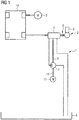
- Figure 1 shows schematically a conveyor 1 with components of a hybrid drive 2 of a schematically illustrated motor vehicle 12.
- the hybrid drive 2 has an internal combustion engine 3 which drives the motor vehicle 12 via a transmission 4, and an electric drive unit 5 for driving the motor vehicle 12 independently of the transmission.
- a clutch separates the internal combustion engine 3 from the transmission 4.
- the delivery device 1 has an oil pump 7 for supplying the transmission 4 with oil and a reservoir 8 designed as an oil pan. Oil delivered by the oil pump 7 reaches the transmission 4 and from there back into the reservoir 8.
- the transmission 4 has a direct drive 9 for driving the oil pump 7. Furthermore, an electric drive 10 with an electric motor 11 is connected to the oil pump 7.
- the oil pump 7 can thus be driven either via the electric drive 10 or via the direct drive 9.
- a parallel operation of the direct drive 9 and the electric drive 10 is also conceivable, for example in order to start up the electric drive 10 at an early stage before the direct drive 9 is switched off.
- the electric drive unit 5 is switched on and the internal combustion engine 3 is switched off.
- the direct drive 9 of the transmission 4 is also switched off.
- the oil pump 7 is driven via the electric drive 10.
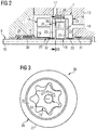
- FIG 2 shows a sectional view through the delivery device 1 with a partial area of the oil pump 7, the electric drive 10 and the direct drive 9 from Figure 1 .
- the oil pump 7 has a stationary housing 13 with a recess 14 for receiving movable components of the oil pump 7 and the electric motor 11 with the electric drive 10.
- the direct drive 9 has a shaft 15 inserted into the recess 14.
- the electric drive 10 has a hollow shaft 16 arranged completely within the recess 14 of the housing 13 and concentrically enclosing the shaft 15.
- the housing 13 also has an inlet connection 17 and an outlet connection 18 of the oil pump 7.
- a rotor 19 of the oil pump 7 is fastened on the shaft 15.
- a rotor part 20 which is rotatable with respect to the rotor 19 is fastened on the hollow shaft 16.
- the rotor part 20 has a ring 21 that radially surrounds the rotor 19 and control plates 22, 23 opposite the end faces of the rotor 19, as well as oil supply elements 24, 25 for the rotor 19.
- the oil supply elements 24, 25 are designed as an inlet opening 26 and an outlet opening 27.
- the inlet opening 26 and the outlet opening 27 are arranged, for example, in the control plates 22, 23.
- the inlet opening 26 and the outlet opening 27 can be arranged in the ring 21 with an appropriately designed oil pump 7 or can be divided between ring 21 and control plates 22, 23.
- Radial seals 28, 29 seal the shaft 15 and the rotor part 20 from the housing 13.
- the direct drive 9 and the electric drive 10 are self-locking designed so that the rotor part 20 is stationary when the electric drive 10 is switched off and the rotor 19 is stationary when the direct drive 9 is switched off.
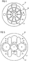
- Figure 3 shows in a sectional view along the line III - III from Figure 2 that the oil pump 7 is designed as a gerotor pump 36.
- An internal rotor 34 that can be driven by the direct drive 9 forms the rotor 19 on which an external rotor 35 rolls.
- the outer rotor 35 is concentric in that of the in Figure 2 illustrated electric drive 10 driven ring 21 arranged. If the ring 21 is rotated via the electric drive 10, the external rotor 35 likewise rolls on the internal rotor 34.
- the in Figure 2 The illustrated inlet opening 26 in one of the control plates 22 is sucked in oil and conveyed to the outlet opening 27 in the other control plate 23.
- FIG Figure 4 shows a further embodiment of the oil pump 7, which extends from FIG Figure 2
- the main difference is that the oil pump 7 is designed as a vane pump 37.
- the rotor 19 here has a rotatable disk 38 with individual vanes 39 which slide along in the non-circular ring 21 of the rotor part 20.
- the ring 21 is connected to the electric drive 10 and the rotor 19 is connected to the direct drive 9.
- FIG Figure 5 shows a further embodiment of the oil pump 7, which extends from FIG Figure 2
- the main difference is that the oil pump 7 is designed as an external gear pump 40.
- the rotor 19 has a central gear 41 and drives gearwheels 42, 43 mounted on the ring 21 of the rotor part 20. If the direction of rotation of the gear wheel 41 of the rotor 19 is provided in a clockwise direction relative to the ring 21, two first channels 44, 45 lead to the FIG Figure 2 inlet opening 26 shown and two second channels 46, 47 to outlet opening 27.
- the connection of the conveyor device 1 to the hybrid drive 2 is only to be understood as an example.
- the conveyor device 1 is also suitable for motor vehicles 12 which are driven exclusively by the internal combustion engine 3.
Landscapes
- Engineering & Computer Science (AREA)
- General Engineering & Computer Science (AREA)
- Mechanical Engineering (AREA)
- Details And Applications Of Rotary Liquid Pumps (AREA)
- Rotary Pumps (AREA)
Description
- Die Erfindung betrifft eine Fördereinrichtung zur Förderung von Öl aus einem Vorratsbehälter zu einem Getriebe eines Kraftfahrzeuges mit einer wahlweise von einem mechanischen Direktantrieb oder von einem zuschaltbaren Elektroantrieb antreibbaren Ölpumpe.
- Solche Fördereinrichtungen werden insbesondere bei Kraftfahrzeugen mit Hybridantrieb eingesetzt. Bei solchen Hybridantrieben wird die Ölpumpe zur Versorgung eines Getriebes direkt von dem Getriebe angetrieben. Bei Stillstand des Getriebes soll dessen Funktion aufrechterhalten werden und daher die Ölpumpe in Betrieb bleiben.
- Aus der
DE 103 29 215 A1 ist eine Antriebsvorrichtung für eine Getriebe-Ölpumpe bekannt, bei der eine einzige Ölpumpe über ein Summiergetriebe wahlweise elektrisch oder direkt angetrieben wird. Hierfür hat das Summiergetriebe zwei Leistungsstränge, wobei ein Leistungsstrang von einem Verbrennungsmotor und der andere Leistungsstrang von einem Elektromotor antreibbar ist. Das Summiergetriebe ist beispielsweise als Planetengetriebe gestaltet. Der Vorteil dieser Gestaltung besteht darin, dass nur eine einzige Ölpumpe eingesetzt werden muss, um die Ölpumpe wahlweise elektrisch oder direkt anzutreiben. Jedoch führt das Summiergetriebe zu einem hohen baulichen Aufwand. DieDE 10 2006 030 041 A ,DE 10 2004 005 430 A undEP-B-1 504 192 offenbaren Fördereinrichtungen mit zwei Antrieben. - Der Erfindung liegt das Problem zugrunde, eine Fördereinrichtung der eingangs genannten Art so weiterzubilden, dass sie besonders einfach aufgebaut und kostengünstig herstellbar ist.
- Dieses Problem wird erfindungsgemäß durch eine Fördereinrichtung nach Anspruch 1 gelöst. Die abhängigen Ansprüche beziehen sich auf besondere Ausführungsarten der Erfindung nach Anspruch 1. Durch diese Gestaltung werden die verschiedenen Möglichkeiten des Antriebs der Ölpumpe durch die entsprechende Gestaltung der Ölpumpe selbst gelöst. Daher wird die Vorschaltung eines Summiergetriebes vor der Ölpumpe vermieden. Die erfindungsgemäße Fördereinrichtung ist daher besonders einfach aufgebaut und kostengünstig herstellbar. Weiterhin ist auch ein Parallelbetrieb des Direktantriebs und des Elektroantriebs denkbar, wenn beispielsweise der Elektroantrieb frühzeitig gestartet werden soll, bevor der Direktantrieb abgeschaltet wird. Ebenso kann die Förderleistung der Ölpumpe durch Zuschaltung des Elektroantriebs angehoben werden, wenn der Direktantrieb bei einem Betriebszustand mit zu geringer Drehzahl läuft.
- Die relativ zueinander beweglichen Bauteile könnten beispielsweise zwei unabhängig voneinander antreibbare Laufräder sein, die sandwichartig übereinander liegen. Dies führt jedoch durch hohe Abmessungen zu einem unnötigen baulichen Aufwand. Der bauliche Aufwand zur Bildung der relativ zueinander beweglichen Bauteile lässt sich gemäß der Erfindung einfach gering halten, wenn die Ölpumpe ein gegenüber einem drehbaren Rotor drehbar gelagertes Läuferteil mit Ölzufuhrelementen für den Rotor hat. Durch diese Gestaltung lassen sich der Rotor der Ölpumpe mit dem Direktantrieb und das Läuferteil der Ölpumpe mit dem zuschaltbaren Elektroantrieb koppeln. Die entgegengesetzte Koppelung ist ebenfalls möglich.
- Die Ölpumpe gestaltet sich gemäß der Erfindung konstruktiv einfach, weil das Läuferteil gegenüber einem feststehenden Gehäuse drehbar gelagert und mittels einer Radialdichtung abgedichtet ist, und wenn Einlass- und Auslassanschlüsse zum hydraulischen Anschluss der Ölpumpe an dem Gehäuse angeordnet sind.
- Die erfindungsgemäße Fördereinrichtung gestaltet sich kompakt, weil das Gehäuse eine gemeinsame Ausnehmung für einen Elektromotor des Elektroantriebs und das Läuferteil und den Rotor der Ölpumpe hat. Weiterhin wird hierdurch der Elektromotor von dem geförderten Öl gekühlt und dessen Geräusche gedämpft. Weiterhin kann hierdurch die Abdichtung einer Wellendurchführung für den Elektroantrieb entfallen.
- Ein vorgesehenes Antriebsmoment beim Betrieb der Ölpumpe durch den Elektroantrieb lässt sich gemäß einer anderen vorteilhaften Weiterbildung der Erfindung einfach einstellen, wenn der Elektroantrieb ein Untersetzungsgetriebe hat.
- Das Läuferteil könnte beispielsweise einen umlaufenden Zahnkranz aufweisen, an dem der jeweilige Antrieb angelenkt ist. Dies führt jedoch zu großen Abmessungen und damit zu einem erhöhten baulichen Aufwand der Ölpumpe. Die Ölpumpe gestaltet sich gemäß der Erfindung besonders kompakt, wenn der Rotor auf einer Welle befestigt ist und das Läuferteil mit einer konzentrisch zu der Welle angeordneten Hohlwelle verbunden ist. Selbstverständlich kann in einer nicht unter den Wortlaut des Anspruchs 1 fallenden Ausführungsart, in kinematischer Umkehr auch der Rotor auf der Hohlwelle und das Läuferteil auf der Welle angeordnet sein. Vorzugsweise ist die Hohlwelle ausschließlich innerhalb des Gehäuses geführt, so dass die Abdichtung einer Wellendurchführung vermieden wird.
- Die Ölpumpe besteht gemäß einer anderen vorteilhaften Weiterbildung der Erfindung aus besonders wenigen zu montierenden Bauteilen, wenn das Läuferteil als innerhalb des Gehäuses angeordnetes Innengehäuse mit einem den Rotor radial umschließenden Ring und den Stirnseiten des Rotors gegenüberstehenden Steuerplatten ausgebildet ist. Vorzugsweise weisen der Ring oder die Steuerplatten die Ölzufuhrelemente für den Rotor auf.
- Zur Vereinfachung des baulichen Aufwandes der Ölpumpe trägt es gemäß einer anderen vorteilhaften Weiterbildung der Erfindung bei, wenn Einlass- und Auslassöffnungen an dem Läuferteil angeordnet sind. Damit dienen die Einlass- und Auslassöffnungen als Ölzufuhrelemente für den Rotor.
- Eine axiale Anströmung oder Durchströmung der Ölpumpe lässt sieh gemäß einer anderen vorteilhaften Weiterbildung der Erfindung einfach erreichen, wenn zumindest eine der Einlass- und Auslassöffnungen an den Steuerplatten des Läuferteils angeordnet ist.
- Eine radiale Abströmung der Ölpumpe lässt sich gemäß einer anderen vorteilhaften Weiterbildung der Erfindung erreichen, wenn zumindest eine der Einlass- und Auslassöffnungen an dem den Rotor umschließenden Ring des Läuferteils angeordnet ist.
- Eine gegenseitige Beeinflussung der Antriebe untereinander lässt sich gemäß einer anderen vorteilhaften Weiterbildung der Erfindung einfach vermeiden, wenn der Direktantrieb und der Elektroantrieb selbsthemmend gestaltet sind.
- Die Ölpumpe lässt sich gemäß einer anderen vorteilhaften Weiterbildung der Erfindung besonders vorteilhaft von zwei unterschiedlichen Antrieben antreiben, wenn die Ölpumpe als Zahnringpumpe, als Flügelzellenpumpe oder als Außenzahnradpumpe ausgebildet ist Bei solchen Pumpprinzipien wirken der entsprechend gestaltete Rotor und ein den Rotor umgebender Ring derartzusammen, dass auf besonders einfache Art wahlweise der Ring oder der Rotor zur Förderung des Öls angetrieben werden kann.
- Die Erfindung lässt zahlreiche Ausführungsformen zu. Zur weiteren Verdeutlichung ihres Grundprinzips sind mehrere davon in der Zeichnung dargestellt und werden nachfolgend beschrieben. Diese zeigt in:
- Fig. 1
- schematisch eine erfindungsgemäße Fördereinrichtung mit angrenzenden Bauteilen eines Kraftfahrzeugs,
- Fig. 2
- eine erste Ausführungsform der Fördereinrichtung mit zwei Antrieben aus
Figur 1 , - Fig. 3
- eine Schnittdarstellung durch die Ölpumpe aus
Figur 2 entlang der Linie III - III, - Fig. 4
- eine Schnittdarstellung durch eine weitere Ausführungsform der Ölpumpe,
- Fig. 5
- eine weitere Ausführungsform der Ölpumpe in einer Schnittdarstellung.
-
Figur 1 zeigt schematisch eine Fördereinrichtung 1 mit Bauteilen eines Hybridantriebs 2 eines schematisch dargestellten Kraftfahrzeuges 12. Der Hybridantrieb 2 hat eine Brennkraftmaschine 3, welche das Kraftfahrzeug 12 über ein Getriebe 4 antreibt, und eine elektrische Antriebseinheit 5 zum Antrieb des Kraftfahrzeuges 12 unabhängig von dem Getriebe. Eine Kupplung trennt die Brennkraftmaschine 3 von dem Getriebe 4. Die Fördereinrichtung 1 hat eine Ölpumpe 7 zur Versorgung des Getriebes 4 mit Öl und einen als Ölwanne ausgebildeten Vorratsbehälter 8. Von der Ölpumpe 7 gefördertes Öl gelangt zu dem Getriebe 4 und von dort wieder zurück in den Vorratsbehälter 8. - Das Getriebe 4 hat einen Direktantrieb 9 zum Antrieb der Ölpumpe 7. Weiterhin ist ein Elektroantrieb 10 mit einem Elektromotor 11 mit der Ölpumpe 7 verbunden. Die Ölpumpe 7 lässt sich damit wahlweise über den Elektroantrieb 10 oder über den Direktantrieb 9 antreiben. Auch ein Parallelbetrieb des Direktantriebes 9 und des Elektroantriebes 10 ist denkbar, um beispielsweise den Elektroantrieb 10 frühzeitig vor dem Abschalten des Direktantriebes 9 hochzufahren. In einem Betriebsmodus des Kraftfahrzeuges 12 wird die elektrische Antriebseinheit 5 zugeschaltet und die Brennkraftmaschine 3 abgeschaltet. In diesem Fall ist auch der Direktantrieb 9 des Getriebes 4 abgeschaltet. Die Ölpumpe 7 wird in diesem Betriebsmodus des Kraftfahrzeuges 12 über den Elektroantrieb 10 angetrieben.
-
Figur 2 zeigt eine Schnittdarstellung durch die Fördereinrichtung 1 mit einem Teilbereich der Ölpumpe 7, dem Elektroantrieb 10 und dem Direktantrieb 9 ausFigur 1 . Hierbei ist zu erkennen, dass die Ölpumpe 7 ein feststehendes Gehäuse 13 mit einer Ausnehmung 14 zur Aufnahme beweglicher Bauteile der Ölpumpe 7 und des Elektromotors 11 mit dem Elektroantrieb 10 hat. Der Direktantrieb 9 hat eine in die Ausnehmung 14 eingeführte Welle 15. Der Elektroantrieb 10 hat eine vollständig innerhalb der Ausnehmung 14 des Gehäuses 13 angeordnete, die Welle 15 konzentrisch umschließende Hohlwelle 16. Das Gehäuse 13 hat zudem einen Einlassanschluss 17 und einen Auslassanschluss 18 der Ölpumpe 7. Auf der Welle 15 ist ein Rotor 19 der Ölpumpe 7 befestigt. Auf der Hohlwelle 16 ist ein gegenüber dem Rotor 19 drehbares Läuferteil 20 befestigt. Das Läuferteil 20 hat einen den Rotor 19 radial umschließenden Ring 21 und den Stirnseiten des Rotors 19 gegenüberstehende Steuerplatten 22, 23, sowie Ölzufuhrelemente 24, 25 für den Rotor 19. Die Ölzufuhrelemente 24, 25 sind als Einlassöffnung 26 und als Auslassöffnung 27 ausgebildet. Die Einlassöffnung 26 und die Auslassöffnung 27 sind beispielhaft in den Steuerplatten 22, 23 angeordnet. Alternativ dazu können die Einlassöffnung 26 und die Auslassöffnung 27 bei entsprechend gestalteter Ölpumpe 7 in dem Ring 21 angeordnet sein oder sich auf Ring 21 und Steuerplatten 22, 23 aufteilen. Radialdichtungen 28, 29 dichten die Welle 15 und das Läuferteil 20 gegenüber dem Gehäuse 13 ab. Mehrere Lagerungen 30 - 33 ermöglichen die drehbare Lagerung der Hohlwelle 16 gegenüber dem Gehäuse 13 und gegenüber der Welle 15. Der Direktantrieb 9 und der Elektroantrieb 10 sind selbsthemmend gestaltet, so dass das Läuferteil 20 feststeht, wenn der Elektroantrieb 10 abgeschaltet ist und der Rotor 19 feststeht, wenn der Direktantrieb 9 abgeschaltet ist. - Dreht man die Welle 15 des Direktantriebs 9, wird der Rotor 19 gegenüber dem Läuferteil 20 verdreht. Dabei wird Öl über den Einlassanschluss 17 und die Einlassöffnung 26 angesaugt und über die Auslassöffnung 27 zu dem Auslassanschluss 18 gefördert. Dreht man die Hohlwelle 16 über den Elektroantrieb 10, wird ausschließlich das Läuferteil 20 mit den Ölzufuhrelementen 24, 25 gegenüber dem Rotor 19 verdreht. Damit wird ebenfalls Öl über den Einlassanschluss 17 angesaugt und zu dem Auslassanschluss 18 im Gehäuse 13 gefördert.
-
Figur 3 zeigt in einer Schnittdarstellung entlang der Linie III - III ausFigur 2 , dass die Ölpumpe 7 als Zahnringpumpe 36 ausgebildet ist. Ein von dem Direktantrieb 9 antreibbarer Innenläufer 34 bildet den Rotor 19, auf dem sich ein Außenläufer 35 abrollt. Der Außenläufer 35 ist konzentrisch in dem von dem inFigur 2 dargestellten Elektroantrieb 10 antreibbaren Ring 21 angeordnet. Wird der Ring 21 über den Elektroantrieb 10 verdreht, rollt sich ebenfalls der Außenläufer 35 auf dem Innenläufer 34 ab. In beiden Fällen wird über die in den inFigur 2 dargestellte Einlassöffnung 26 in einer der Steuerplatten 22 Öl angesaugt und zu der Auslassöffnung 27 in der anderen Steuerplatte 23 gefördert. -
Figur 4 zeigt eine weitere Ausführungsform der Ölpumpe 7, welche sich von der ausFigur 2 vor allem dadurch unterscheidet, dass die Ölpumpe 7 als Flügelzellenpumpe 37 ausgebildet ist. Der Rotor 19 weist hier eine drehbare Scheibe 38 mit einzelnen Flügeln 39 auf, welche in dem unrund gestalteten Ring 21 des Läuferteils 20 entlang gleiten. Wie bei den vorangegangenen Ausführungsformen ist der Ring 21 mit dem Elektroantrieb 10 und der Rotor 19 mit dem Direktantrieb 9 verbunden. -
Figur 5 zeigt eine weitere Ausführungsform der Ölpumpe 7, welche sich von der ausFigur 2 vor allem dadurch unterscheidet, dass die Ölpumpe 7 als Außenzahnradpumpe 40 ausgebildet ist. Der Rotor 19 hat ein zentrisches Zahnrad 41 und treibt auf dem Ring 21 des Läuferteils 20 gelagerte Zahnräder 42, 43 an. Bei einer vorgesehenen Drehrichtung des Zahnrades 41 des Rotors 19 relativ zu dem Ring 21 im Uhrzeigersinn führen zwei erste Kanäle 44, 45 zu der inFigur 2 dargestellten Einlassöffnung 26 und zwei zweite Kanäle 46, 47 zu der Auslassöffnung 27. - Die Verbindung der Fördereinrichtung 1 mit dem Hybridantrieb 2 ist nur beispielhaft zu verstehen. Die Fördereinrichtung 1 eignet sich ebenfalls für Kraftfahrzeuge 12, welche ausschließlich über die Brennkraftmaschine 3 angetrieben sind.
Claims (8)
- Fördereinrichtung (1) zur Förderung von Öl aus einem Vorratsbehälter (8) zu einem Getriebe (4) eines Kraftfahrzeuges (12) mit einer wahlweise von einem mechanischen Direktantrieb (9) oder von einem zuschaltbaren Elektroantrieb (10) antreibbaren Ölpumpe (7), wobei die Ölpumpe (7) zwei relativ zueinander bewegliche Bauteile zur Förderung des Öls hat und der mechanische Direktantrieb (9) mit einem der relativ zueinander beweglichen Bauteile und der zuschaltbare Elektroantrieb (10) mit dem anderen der relativ zueinander beweglichen Bauteile verbunden ist, wobei die Ölpumpe (7) ein gegenüber einem drehbaren Rotor (19) drehbar gelagertes Läuferteil (20) mit Ölzufuhrelementen (24, 25, 57, 58) für den Rotor (19) hat und wobei der Rotor (19) auf einer Welle (15, 54) befestigt ist und das Läuferteil (20) mit einer konzentrisch zu der Welle (15, 54) angeordneten Hohlwelle (16, 53) verbunden ist, wobei das Läuferteil (20) gegenüber einem feststehenden Gehäuse (13, 52) drehbar gelagert und mittels einer Radialdichtung (28) abgedichtet ist und wobei Einlass- und Auslassanschlüsse (17, 18, 60, 61) zum hydraulischen Anschluss der Ölpumpe (7) an dem Gehäuse (13, 52) angeordnet sind, wobei das Gehäuse (13) eine gemeinsame Ausnehmung (14) für einen Elektromotor (11) des Elektroantriebs (10) und das Läuferteil (20) und den Rotor (19) der Ölpumpe (7) hat.
- Fördereinrichtung nach Anspruch 1, dadurch gekennzeichnet, dass der Elektroantrieb (10) ein Untersetzungsgetriebe (59) hat.
- Fördereinrichtung nach Anspruch 1 oder 2, dadurch gekennzeichnet, dass das Läuferteil (20) als innerhalb des Gehäuses (13, 52) angeordnetes Innengehäuse mit einem den Rotor (19) radial umschließenden Ring (21) und den Stirnseiten des Rotors (19) gegenüberstehenden Steuerplatten (22, 23) ausgebildet ist.
- Fördereinrichtung nach einem der Ansprüche 1 bis 3, dadurch gekennzeichnet, dass Einlass- und Auslassöffnungen (26, 27, 55, 56) an dem Läuferteil (20) angeordnet sind.
- Fördereinrichtung nach Anspruch 3 und 4, dadurch gekennzeichnet, dass zumindest eine der Einlass- und Auslassöffnungen (26, 27, 55, 56) an den Steuerplatten (22, 23) des Läuferteils (20) angeordnet ist.
- Fördereinrichtung nach Anspruch 4, dadurch gekennzeichnet, dass zumindest eine der Einlass- und Auslassöffnungen (26, 27, 55, 56) an dem den Rotor (19) umschließenden Ring (21) des Läuferteils (20) angeordnet ist.
- Fördereinrichtung nach einem der Ansprüche 1 bis 6, dadurch gekennzeichnet, dass der Direktantrieb (9) und der Elektroantrieb (10) selbsthemmend gestaltet sind.
- Fördereinrichtung nach einem der Ansprüche 1 bis 7, dadurch gekennzeichnet, dass die Ölpumpe (7) als Zahnringpumpe (36), als Flügelzellenpumpe (37) oder als Außenzahnradpumpe (40) ausgebildet ist.
Applications Claiming Priority (2)
| Application Number | Priority Date | Filing Date | Title |
|---|---|---|---|
| DE102011084542A DE102011084542A1 (de) | 2011-10-14 | 2011-10-14 | Fördereinrichtung zur Förderung von Öl aus einem Vorratsbehälter zu einem Getriebe eines Kraftfahrzeuges |
| PCT/EP2012/070210 WO2013053854A1 (de) | 2011-10-14 | 2012-10-11 | Fördereinrichtung zur förderung von öl aus einem vorratsbehälter zu einem getriebe eines kraftfahrzeuges |
Publications (3)
| Publication Number | Publication Date |
|---|---|
| EP2766638A1 EP2766638A1 (de) | 2014-08-20 |
| EP2766638B1 EP2766638B1 (de) | 2018-01-24 |
| EP2766638B2 true EP2766638B2 (de) | 2021-11-24 |
Family
ID=47115818
Family Applications (1)
| Application Number | Title | Priority Date | Filing Date |
|---|---|---|---|
| EP12780141.3A Active EP2766638B2 (de) | 2011-10-14 | 2012-10-11 | Fördereinrichtung zur förderung von öl aus einem vorratsbehälter zu einem getriebe eines kraftfahrzeuges |
Country Status (5)
| Country | Link |
|---|---|
| US (1) | US10072660B2 (de) |
| EP (1) | EP2766638B2 (de) |
| CN (1) | CN103890460B (de) |
| DE (1) | DE102011084542A1 (de) |
| WO (1) | WO2013053854A1 (de) |
Families Citing this family (14)
| Publication number | Priority date | Publication date | Assignee | Title |
|---|---|---|---|---|
| DE102013213051A1 (de) * | 2013-06-18 | 2014-12-18 | Continental Automotive Gmbh | Fördereinrichtung zur Förderung von Öl aus einem Vorratsbehälter zu einem Getriebe eines Kraftfahrzeuges |
| CN105531481B (zh) * | 2013-09-30 | 2017-06-13 | 爱信艾达株式会社 | 车辆用油压供给装置 |
| DE102014212487A1 (de) * | 2014-06-27 | 2015-12-31 | Zf Friedrichshafen Ag | Planetengetriebe mit Notschmiervorrichtung |
| DE102015219771A1 (de) | 2015-10-13 | 2017-04-13 | Continental Automotive Gmbh | Fördereinrichtung für ein Kraftfahrzeug |
| DE102015221891A1 (de) * | 2015-11-06 | 2017-05-11 | Continental Automotive Gmbh | Fördereinrichtung zur Förderung von Öl |
| DE102015221901A1 (de) * | 2015-11-06 | 2017-05-11 | Continental Automotive Gmbh | Fördereinrichtung zur Förderung von Öl aus einem Ölsumpf zu einem Schmierölkreislauf |
| US20180363761A1 (en) * | 2015-12-14 | 2018-12-20 | Pierburg-Pump Technology Gmbh | Hybrid oil pump |
| GB2558214B (en) | 2016-12-22 | 2021-07-21 | Concentric Birmingham Ltd | Auxiliary drive system for a pump |
| US10920772B2 (en) * | 2017-10-09 | 2021-02-16 | Chilldyne, Inc. | Dual motor gear pump |
| DE102019208845A1 (de) * | 2019-06-18 | 2020-12-24 | Vitesco Technologies GmbH | Pumpenstufenanordnung, Außenzahnradpumpe, Verwendung einer Pumpenstufenanordnung und Fahrzeuggetriebe |
| CH716640A2 (de) * | 2019-09-27 | 2021-03-31 | Liebherr Machines Bulle Sa | Doppelpumpe und Ölfördervorrichtung zum Pumpen von Öl für eine Verbrennungskraftmaschine. |
| US11473575B2 (en) | 2020-05-15 | 2022-10-18 | Hanon Systems EFP Canada Ltd. | Dual drive vane pump |
| US11624363B2 (en) | 2020-05-15 | 2023-04-11 | Hanon Systems EFP Canada Ltd. | Dual drive gerotor pump |
| US11649822B2 (en) | 2021-02-08 | 2023-05-16 | Schaeffler Technologies AG & Co. KG | Split power gerotor pump |
Family Cites Families (20)
| Publication number | Priority date | Publication date | Assignee | Title |
|---|---|---|---|---|
| US4931249A (en) * | 1987-04-20 | 1990-06-05 | Thermal Designs, Inc. | Apparatus and process for mixing and dispensing high viscosity, multiple component reactive liquids into a mold |
| JP2669676B2 (ja) | 1988-12-06 | 1997-10-29 | 株式会社山田製作所 | トロコイド型オイルポンプ |
| DE4012789A1 (de) | 1990-04-21 | 1991-10-24 | Maso Dickstoffpumpen Entwicklu | Umlaufpumpe |
| JP3343660B2 (ja) * | 1992-12-10 | 2002-11-11 | 本田技研工業株式会社 | オイルポンプ駆動装置 |
| US6234769B1 (en) * | 1997-07-09 | 2001-05-22 | Denso Corporation | Hybrid type compressor driven by engine and electric motor |
| DE19750675C1 (de) * | 1997-11-15 | 1998-08-13 | Zahnradfabrik Friedrichshafen | Ölpumpe |
| US7186101B2 (en) * | 1998-07-31 | 2007-03-06 | The Texas A&M University System | Gerotor apparatus for a quasi-isothermal Brayton cycle Engine |
| US6749272B2 (en) | 2001-08-09 | 2004-06-15 | Denso Corporation | Rotary pump with higher discharge pressure and brake apparatus having same |
| JP3700650B2 (ja) * | 2002-01-15 | 2005-09-28 | 株式会社デンソー | ハイブリッドコンプレッサおよびハイブリッドコンプレッサ装置 |
| ITBO20020275A1 (it) | 2002-05-10 | 2003-11-10 | Pierburg Spa | Pompa rotativa a portata variabile , in particolare per olio |
| DE10329215A1 (de) | 2003-06-28 | 2005-01-13 | Zf Friedrichshafen Ag | Antriebsvorrichtung für eine Getriebe-Ölpumpe und Verfahren zum Betreiben derselben |
| DE102004005430A1 (de) * | 2004-02-04 | 2005-08-25 | Zf Friedrichshafen Ag | Ölpumpe für Kraftfahrzeug-Automatgetriebe |
| DE102005013137A1 (de) | 2005-03-22 | 2006-09-28 | Zf Friedrichshafen Ag | Verfahren und Vorrichtung zur Steuerung einer Ölversorgung für ein Automatgetriebe und ein Anfahrelement |
| EP1840327A3 (de) * | 2006-03-28 | 2007-12-26 | JTEKT Corporation | Innenzahnradpumpe |
| DE102006030041A1 (de) * | 2006-06-29 | 2008-01-03 | Zf Friedrichshafen Ag | Pumpenvorrichtung eines Fahrzeuggetriebes |
| JP4369966B2 (ja) * | 2007-07-18 | 2009-11-25 | アイシン・エィ・ダブリュ株式会社 | ハイブリッド車両用駆動装置 |
| DE102008040665A1 (de) * | 2008-07-24 | 2010-06-17 | Zf Friedrichshafen Ag | Verfahren zur Steuerung der Ölversorgungseinrichtung eines Planeten-Automatgetriebes |
| US8182235B2 (en) | 2008-11-25 | 2012-05-22 | Toyota Motor Engineering & Manufacturing North America, Inc. | Multi-drive fluid pump |
| US8162625B1 (en) * | 2009-09-22 | 2012-04-24 | Harry Soderstrom | Nested motor, reduction motor reduction gear and pump with selectable mounting options |
| US8640452B2 (en) | 2010-01-19 | 2014-02-04 | GM Global Technology Operations LLC | Hydraulic circuit for a power transmission device |
-
2011
- 2011-10-14 DE DE102011084542A patent/DE102011084542A1/de not_active Ceased
-
2012
- 2012-10-11 WO PCT/EP2012/070210 patent/WO2013053854A1/de active Application Filing
- 2012-10-11 EP EP12780141.3A patent/EP2766638B2/de active Active
- 2012-10-11 CN CN201280050266.6A patent/CN103890460B/zh active Active
- 2012-10-11 US US14/351,363 patent/US10072660B2/en active Active
Also Published As
| Publication number | Publication date |
|---|---|
| CN103890460A (zh) | 2014-06-25 |
| CN103890460B (zh) | 2016-11-02 |
| EP2766638A1 (de) | 2014-08-20 |
| DE102011084542A1 (de) | 2013-04-18 |
| US10072660B2 (en) | 2018-09-11 |
| WO2013053854A1 (de) | 2013-04-18 |
| US20140286801A1 (en) | 2014-09-25 |
| EP2766638B1 (de) | 2018-01-24 |
Similar Documents
| Publication | Publication Date | Title |
|---|---|---|
| EP2766638B2 (de) | Fördereinrichtung zur förderung von öl aus einem vorratsbehälter zu einem getriebe eines kraftfahrzeuges | |
| EP3516250B1 (de) | Mehrfachkupplungseinrichtung und hybridmodul für ein kraftfahrzeug | |
| DE102014114889A1 (de) | Antriebseinheit für Fahrzeuge | |
| DE102008033434A1 (de) | Fahrzeug-Antriebsstrang mit Direkt-Leistungsentnahme-Stelle | |
| DE102006008430A1 (de) | Antriebseinrichtung für die Ölpumpe eines Kraftfahrzeuggetriebes | |
| EP2606259B1 (de) | Leistungsverzweigungsgetriebe für ein kraftfahrzeug | |
| DE1949973C3 (de) | Hydrostatisches Aggregat | |
| DE102010054250A1 (de) | Hydrauliksteuerung | |
| DE102009001458A1 (de) | Elektromaschine | |
| DE102019204189A1 (de) | Getriebe und Antriebsstrang für ein Kraftfahrzeug | |
| WO2014202366A1 (de) | Fördereinrichtung zur förderung von öl aus einem vorratsbehälter zu einem getriebe eines kraftfahrzeuges | |
| EP3245426B1 (de) | Ölpumpenanordnung für ein kraftfahrzeug | |
| DE102007007996B4 (de) | Antrieb für die Grabtrommel eines Tagebaugewinnungsgerätes | |
| EP0716966B1 (de) | Antriebseinheit | |
| EP1747969B1 (de) | Antriebseinheit | |
| WO2007098849A1 (de) | Förderpumpe in einem kraftfahrzeug | |
| EP2625427B1 (de) | Strömungsgetriebe | |
| DE602004002679T2 (de) | Modulares getriebesystem für pumpe | |
| WO2017207122A1 (de) | Ölpumpenantrieb für ein getriebe eines kraftfahrzeugs | |
| DE102018110198B3 (de) | Zentrifugenaufbau | |
| WO2014023744A1 (de) | Pumpeneinrichtung | |
| DE102019219048A1 (de) | Kraftfahrzeuggetriebe mit einem Nebenabtrieb | |
| WO2017045759A1 (de) | Antriebsvorrichtung mit umlauffilterung | |
| DE102019117346B3 (de) | Elektromechanische Wasserpumpe mit Freilauf | |
| DE102022003889A1 (de) | Elektrische Antriebsvorrichtung für ein Kraftfahrzeug |
Legal Events
| Date | Code | Title | Description |
|---|---|---|---|
| PUAI | Public reference made under article 153(3) epc to a published international application that has entered the european phase |
Free format text: ORIGINAL CODE: 0009012 |
|
| 17P | Request for examination filed |
Effective date: 20140514 |
|
| AK | Designated contracting states |
Kind code of ref document: A1 Designated state(s): AL AT BE BG CH CY CZ DE DK EE ES FI FR GB GR HR HU IE IS IT LI LT LU LV MC MK MT NL NO PL PT RO RS SE SI SK SM TR |
|
| DAX | Request for extension of the european patent (deleted) | ||
| RIC1 | Information provided on ipc code assigned before grant |
Ipc: F16H 61/00 20060101ALI20170803BHEP Ipc: F16H 57/04 20100101AFI20170803BHEP Ipc: F04C 2/00 20060101ALN20170803BHEP Ipc: F04C 2/18 20060101ALN20170803BHEP Ipc: F04C 29/00 20060101ALI20170803BHEP Ipc: F04C 15/00 20060101ALI20170803BHEP Ipc: F16N 13/20 20060101ALI20170803BHEP Ipc: F04C 2/344 20060101ALI20170803BHEP Ipc: F04C 2/08 20060101ALI20170803BHEP Ipc: F04C 2/10 20060101ALN20170803BHEP |
|
| GRAP | Despatch of communication of intention to grant a patent |
Free format text: ORIGINAL CODE: EPIDOSNIGR1 |
|
| STAA | Information on the status of an ep patent application or granted ep patent |
Free format text: STATUS: GRANT OF PATENT IS INTENDED |
|
| INTG | Intention to grant announced |
Effective date: 20170912 |
|
| GRAS | Grant fee paid |
Free format text: ORIGINAL CODE: EPIDOSNIGR3 |
|
| GRAA | (expected) grant |
Free format text: ORIGINAL CODE: 0009210 |
|
| STAA | Information on the status of an ep patent application or granted ep patent |
Free format text: STATUS: THE PATENT HAS BEEN GRANTED |
|
| AK | Designated contracting states |
Kind code of ref document: B1 Designated state(s): AL AT BE BG CH CY CZ DE DK EE ES FI FR GB GR HR HU IE IS IT LI LT LU LV MC MK MT NL NO PL PT RO RS SE SI SK SM TR |
|
| REG | Reference to a national code |
Ref country code: GB Ref legal event code: FG4D Free format text: NOT ENGLISH |
|
| REG | Reference to a national code |
Ref country code: CH Ref legal event code: EP |
|
| REG | Reference to a national code |
Ref country code: AT Ref legal event code: REF Ref document number: 965956 Country of ref document: AT Kind code of ref document: T Effective date: 20180215 |
|
| REG | Reference to a national code |
Ref country code: IE Ref legal event code: FG4D Free format text: LANGUAGE OF EP DOCUMENT: GERMAN |
|
| REG | Reference to a national code |
Ref country code: DE Ref legal event code: R096 Ref document number: 502012012085 Country of ref document: DE |
|
| REG | Reference to a national code |
Ref country code: NL Ref legal event code: MP Effective date: 20180124 |
|
| REG | Reference to a national code |
Ref country code: LT Ref legal event code: MG4D |
|
| PG25 | Lapsed in a contracting state [announced via postgrant information from national office to epo] |
Ref country code: NL Free format text: LAPSE BECAUSE OF FAILURE TO SUBMIT A TRANSLATION OF THE DESCRIPTION OR TO PAY THE FEE WITHIN THE PRESCRIBED TIME-LIMIT Effective date: 20180124 |
|
| PG25 | Lapsed in a contracting state [announced via postgrant information from national office to epo] |
Ref country code: HR Free format text: LAPSE BECAUSE OF FAILURE TO SUBMIT A TRANSLATION OF THE DESCRIPTION OR TO PAY THE FEE WITHIN THE PRESCRIBED TIME-LIMIT Effective date: 20180124 Ref country code: LT Free format text: LAPSE BECAUSE OF FAILURE TO SUBMIT A TRANSLATION OF THE DESCRIPTION OR TO PAY THE FEE WITHIN THE PRESCRIBED TIME-LIMIT Effective date: 20180124 Ref country code: FI Free format text: LAPSE BECAUSE OF FAILURE TO SUBMIT A TRANSLATION OF THE DESCRIPTION OR TO PAY THE FEE WITHIN THE PRESCRIBED TIME-LIMIT Effective date: 20180124 Ref country code: NO Free format text: LAPSE BECAUSE OF FAILURE TO SUBMIT A TRANSLATION OF THE DESCRIPTION OR TO PAY THE FEE WITHIN THE PRESCRIBED TIME-LIMIT Effective date: 20180424 Ref country code: ES Free format text: LAPSE BECAUSE OF FAILURE TO SUBMIT A TRANSLATION OF THE DESCRIPTION OR TO PAY THE FEE WITHIN THE PRESCRIBED TIME-LIMIT Effective date: 20180124 Ref country code: CY Free format text: LAPSE BECAUSE OF FAILURE TO SUBMIT A TRANSLATION OF THE DESCRIPTION OR TO PAY THE FEE WITHIN THE PRESCRIBED TIME-LIMIT Effective date: 20180124 |
|
| PG25 | Lapsed in a contracting state [announced via postgrant information from national office to epo] |
Ref country code: PL Free format text: LAPSE BECAUSE OF FAILURE TO SUBMIT A TRANSLATION OF THE DESCRIPTION OR TO PAY THE FEE WITHIN THE PRESCRIBED TIME-LIMIT Effective date: 20180124 Ref country code: RS Free format text: LAPSE BECAUSE OF FAILURE TO SUBMIT A TRANSLATION OF THE DESCRIPTION OR TO PAY THE FEE WITHIN THE PRESCRIBED TIME-LIMIT Effective date: 20180124 Ref country code: GR Free format text: LAPSE BECAUSE OF FAILURE TO SUBMIT A TRANSLATION OF THE DESCRIPTION OR TO PAY THE FEE WITHIN THE PRESCRIBED TIME-LIMIT Effective date: 20180425 Ref country code: LV Free format text: LAPSE BECAUSE OF FAILURE TO SUBMIT A TRANSLATION OF THE DESCRIPTION OR TO PAY THE FEE WITHIN THE PRESCRIBED TIME-LIMIT Effective date: 20180124 Ref country code: SE Free format text: LAPSE BECAUSE OF FAILURE TO SUBMIT A TRANSLATION OF THE DESCRIPTION OR TO PAY THE FEE WITHIN THE PRESCRIBED TIME-LIMIT Effective date: 20180124 Ref country code: IS Free format text: LAPSE BECAUSE OF FAILURE TO SUBMIT A TRANSLATION OF THE DESCRIPTION OR TO PAY THE FEE WITHIN THE PRESCRIBED TIME-LIMIT Effective date: 20180524 Ref country code: BG Free format text: LAPSE BECAUSE OF FAILURE TO SUBMIT A TRANSLATION OF THE DESCRIPTION OR TO PAY THE FEE WITHIN THE PRESCRIBED TIME-LIMIT Effective date: 20180424 |
|
| PG25 | Lapsed in a contracting state [announced via postgrant information from national office to epo] |
Ref country code: MT Free format text: LAPSE BECAUSE OF FAILURE TO SUBMIT A TRANSLATION OF THE DESCRIPTION OR TO PAY THE FEE WITHIN THE PRESCRIBED TIME-LIMIT Effective date: 20180124 |
|
| REG | Reference to a national code |
Ref country code: FR Ref legal event code: PLFP Year of fee payment: 7 |
|
| REG | Reference to a national code |
Ref country code: DE Ref legal event code: R026 Ref document number: 502012012085 Country of ref document: DE |
|
| PLBI | Opposition filed |
Free format text: ORIGINAL CODE: 0009260 |
|
| PG25 | Lapsed in a contracting state [announced via postgrant information from national office to epo] |
Ref country code: AL Free format text: LAPSE BECAUSE OF FAILURE TO SUBMIT A TRANSLATION OF THE DESCRIPTION OR TO PAY THE FEE WITHIN THE PRESCRIBED TIME-LIMIT Effective date: 20180124 Ref country code: EE Free format text: LAPSE BECAUSE OF FAILURE TO SUBMIT A TRANSLATION OF THE DESCRIPTION OR TO PAY THE FEE WITHIN THE PRESCRIBED TIME-LIMIT Effective date: 20180124 Ref country code: RO Free format text: LAPSE BECAUSE OF FAILURE TO SUBMIT A TRANSLATION OF THE DESCRIPTION OR TO PAY THE FEE WITHIN THE PRESCRIBED TIME-LIMIT Effective date: 20180124 |
|
| PLAX | Notice of opposition and request to file observation + time limit sent |
Free format text: ORIGINAL CODE: EPIDOSNOBS2 |
|
| 26 | Opposition filed |
Opponent name: ZF FRIEDRICHSHAFEN AG Effective date: 20181024 |
|
| PG25 | Lapsed in a contracting state [announced via postgrant information from national office to epo] |
Ref country code: SK Free format text: LAPSE BECAUSE OF FAILURE TO SUBMIT A TRANSLATION OF THE DESCRIPTION OR TO PAY THE FEE WITHIN THE PRESCRIBED TIME-LIMIT Effective date: 20180124 Ref country code: CZ Free format text: LAPSE BECAUSE OF FAILURE TO SUBMIT A TRANSLATION OF THE DESCRIPTION OR TO PAY THE FEE WITHIN THE PRESCRIBED TIME-LIMIT Effective date: 20180124 Ref country code: SM Free format text: LAPSE BECAUSE OF FAILURE TO SUBMIT A TRANSLATION OF THE DESCRIPTION OR TO PAY THE FEE WITHIN THE PRESCRIBED TIME-LIMIT Effective date: 20180124 Ref country code: DK Free format text: LAPSE BECAUSE OF FAILURE TO SUBMIT A TRANSLATION OF THE DESCRIPTION OR TO PAY THE FEE WITHIN THE PRESCRIBED TIME-LIMIT Effective date: 20180124 |
|
| PG25 | Lapsed in a contracting state [announced via postgrant information from national office to epo] |
Ref country code: SI Free format text: LAPSE BECAUSE OF FAILURE TO SUBMIT A TRANSLATION OF THE DESCRIPTION OR TO PAY THE FEE WITHIN THE PRESCRIBED TIME-LIMIT Effective date: 20180124 |
|
| REG | Reference to a national code |
Ref country code: CH Ref legal event code: PL |
|
| GBPC | Gb: european patent ceased through non-payment of renewal fee |
Effective date: 20181011 |
|
| REG | Reference to a national code |
Ref country code: BE Ref legal event code: MM Effective date: 20181031 |
|
| PG25 | Lapsed in a contracting state [announced via postgrant information from national office to epo] |
Ref country code: LU Free format text: LAPSE BECAUSE OF NON-PAYMENT OF DUE FEES Effective date: 20181011 Ref country code: MC Free format text: LAPSE BECAUSE OF FAILURE TO SUBMIT A TRANSLATION OF THE DESCRIPTION OR TO PAY THE FEE WITHIN THE PRESCRIBED TIME-LIMIT Effective date: 20180124 |
|
| REG | Reference to a national code |
Ref country code: IE Ref legal event code: MM4A |
|
| PG25 | Lapsed in a contracting state [announced via postgrant information from national office to epo] |
Ref country code: BE Free format text: LAPSE BECAUSE OF NON-PAYMENT OF DUE FEES Effective date: 20181031 Ref country code: CH Free format text: LAPSE BECAUSE OF NON-PAYMENT OF DUE FEES Effective date: 20181031 Ref country code: LI Free format text: LAPSE BECAUSE OF NON-PAYMENT OF DUE FEES Effective date: 20181031 |
|
| PG25 | Lapsed in a contracting state [announced via postgrant information from national office to epo] |
Ref country code: GB Free format text: LAPSE BECAUSE OF NON-PAYMENT OF DUE FEES Effective date: 20181011 Ref country code: IE Free format text: LAPSE BECAUSE OF NON-PAYMENT OF DUE FEES Effective date: 20181011 |
|
| PLBB | Reply of patent proprietor to notice(s) of opposition received |
Free format text: ORIGINAL CODE: EPIDOSNOBS3 |
|
| REG | Reference to a national code |
Ref country code: AT Ref legal event code: MM01 Ref document number: 965956 Country of ref document: AT Kind code of ref document: T Effective date: 20181011 |
|
| PG25 | Lapsed in a contracting state [announced via postgrant information from national office to epo] |
Ref country code: AT Free format text: LAPSE BECAUSE OF NON-PAYMENT OF DUE FEES Effective date: 20181011 |
|
| PG25 | Lapsed in a contracting state [announced via postgrant information from national office to epo] |
Ref country code: TR Free format text: LAPSE BECAUSE OF FAILURE TO SUBMIT A TRANSLATION OF THE DESCRIPTION OR TO PAY THE FEE WITHIN THE PRESCRIBED TIME-LIMIT Effective date: 20180124 |
|
| RAP2 | Party data changed (patent owner data changed or rights of a patent transferred) |
Owner name: VITESCO TECHNOLOGIES GMBH |
|
| PG25 | Lapsed in a contracting state [announced via postgrant information from national office to epo] |
Ref country code: PT Free format text: LAPSE BECAUSE OF FAILURE TO SUBMIT A TRANSLATION OF THE DESCRIPTION OR TO PAY THE FEE WITHIN THE PRESCRIBED TIME-LIMIT Effective date: 20180124 |
|
| REG | Reference to a national code |
Ref country code: DE Ref legal event code: R081 Ref document number: 502012012085 Country of ref document: DE Owner name: VITESCO TECHNOLOGIES GMBH, DE Free format text: FORMER OWNER: CONTINENTAL AUTOMOTIVE GMBH, 30165 HANNOVER, DE |
|
| PG25 | Lapsed in a contracting state [announced via postgrant information from national office to epo] |
Ref country code: HU Free format text: LAPSE BECAUSE OF FAILURE TO SUBMIT A TRANSLATION OF THE DESCRIPTION OR TO PAY THE FEE WITHIN THE PRESCRIBED TIME-LIMIT; INVALID AB INITIO Effective date: 20121011 Ref country code: MK Free format text: LAPSE BECAUSE OF NON-PAYMENT OF DUE FEES Effective date: 20180124 |
|
| PUAH | Patent maintained in amended form |
Free format text: ORIGINAL CODE: 0009272 |
|
| STAA | Information on the status of an ep patent application or granted ep patent |
Free format text: STATUS: PATENT MAINTAINED AS AMENDED |
|
| 27A | Patent maintained in amended form |
Effective date: 20211124 |
|
| AK | Designated contracting states |
Kind code of ref document: B2 Designated state(s): AL AT BE BG CH CY CZ DE DK EE ES FI FR GB GR HR HU IE IS IT LI LT LU LV MC MK MT NL NO PL PT RO RS SE SI SK SM TR |
|
| REG | Reference to a national code |
Ref country code: DE Ref legal event code: R102 Ref document number: 502012012085 Country of ref document: DE |
|
| REG | Reference to a national code |
Ref country code: DE Ref legal event code: R081 Ref document number: 502012012085 Country of ref document: DE Owner name: VITESCO TECHNOLOGIES GMBH, DE Free format text: FORMER OWNER: VITESCO TECHNOLOGIES GMBH, 30165 HANNOVER, DE |
|
| REG | Reference to a national code |
Ref country code: DE Ref legal event code: R084 Ref document number: 502012012085 Country of ref document: DE |
|
| P01 | Opt-out of the competence of the unified patent court (upc) registered |
Effective date: 20230530 |
|
| PGFP | Annual fee paid to national office [announced via postgrant information from national office to epo] |
Ref country code: IT Payment date: 20231026 Year of fee payment: 12 Ref country code: FR Payment date: 20231025 Year of fee payment: 12 Ref country code: DE Payment date: 20231031 Year of fee payment: 12 |