EP2765586B1 - Dispositif de contact et contacteur magnétique le mettant en oeuvre - Google Patents
Dispositif de contact et contacteur magnétique le mettant en oeuvre Download PDFInfo
- Publication number
- EP2765586B1 EP2765586B1 EP12838528.3A EP12838528A EP2765586B1 EP 2765586 B1 EP2765586 B1 EP 2765586B1 EP 12838528 A EP12838528 A EP 12838528A EP 2765586 B1 EP2765586 B1 EP 2765586B1
- Authority
- EP
- European Patent Office
- Prior art keywords
- contact
- plate portion
- movable
- movable contact
- fixed
- Prior art date
- Legal status (The legal status is an assumption and is not a legal conclusion. Google has not performed a legal analysis and makes no representation as to the accuracy of the status listed.)
- Not-in-force
Links
Images


Classifications
-
- H—ELECTRICITY
- H01—ELECTRIC ELEMENTS
- H01H—ELECTRIC SWITCHES; RELAYS; SELECTORS; EMERGENCY PROTECTIVE DEVICES
- H01H50/00—Details of electromagnetic relays
- H01H50/54—Contact arrangements
-
- H—ELECTRICITY
- H01—ELECTRIC ELEMENTS
- H01H—ELECTRIC SWITCHES; RELAYS; SELECTORS; EMERGENCY PROTECTIVE DEVICES
- H01H1/00—Contacts
- H01H1/50—Means for increasing contact pressure, preventing vibration of contacts, holding contacts together after engagement, or biasing contacts to the open position
- H01H1/54—Means for increasing contact pressure, preventing vibration of contacts, holding contacts together after engagement, or biasing contacts to the open position by magnetic force
-
- H—ELECTRICITY
- H01—ELECTRIC ELEMENTS
- H01H—ELECTRIC SWITCHES; RELAYS; SELECTORS; EMERGENCY PROTECTIVE DEVICES
- H01H50/00—Details of electromagnetic relays
- H01H50/54—Contact arrangements
- H01H50/546—Contact arrangements for contactors having bridging contacts
-
- H—ELECTRICITY
- H01—ELECTRIC ELEMENTS
- H01H—ELECTRIC SWITCHES; RELAYS; SELECTORS; EMERGENCY PROTECTIVE DEVICES
- H01H50/00—Details of electromagnetic relays
- H01H50/64—Driving arrangements between movable part of magnetic circuit and contact
- H01H50/641—Driving arrangements between movable part of magnetic circuit and contact intermediate part performing a rectilinear movement
-
- H—ELECTRICITY
- H01—ELECTRIC ELEMENTS
- H01H—ELECTRIC SWITCHES; RELAYS; SELECTORS; EMERGENCY PROTECTIVE DEVICES
- H01H51/00—Electromagnetic relays
- H01H51/22—Polarised relays
- H01H51/2209—Polarised relays with rectilinearly movable armature
-
- H—ELECTRICITY
- H01—ELECTRIC ELEMENTS
- H01H—ELECTRIC SWITCHES; RELAYS; SELECTORS; EMERGENCY PROTECTIVE DEVICES
- H01H71/00—Details of the protective switches or relays covered by groups H01H73/00 - H01H83/00
- H01H71/10—Operating or release mechanisms
-
- H—ELECTRICITY
- H01—ELECTRIC ELEMENTS
- H01H—ELECTRIC SWITCHES; RELAYS; SELECTORS; EMERGENCY PROTECTIVE DEVICES
- H01H9/00—Details of switching devices, not covered by groups H01H1/00 - H01H7/00
- H01H9/30—Means for extinguishing or preventing arc between current-carrying parts
- H01H9/44—Means for extinguishing or preventing arc between current-carrying parts using blow-out magnet
- H01H9/443—Means for extinguishing or preventing arc between current-carrying parts using blow-out magnet using permanent magnets
-
- H—ELECTRICITY
- H01—ELECTRIC ELEMENTS
- H01H—ELECTRIC SWITCHES; RELAYS; SELECTORS; EMERGENCY PROTECTIVE DEVICES
- H01H50/00—Details of electromagnetic relays
- H01H50/02—Bases; Casings; Covers
- H01H50/023—Details concerning sealing, e.g. sealing casing with resin
- H01H2050/025—Details concerning sealing, e.g. sealing casing with resin containing inert or dielectric gasses, e.g. SF6, for arc prevention or arc extinction
-
- H—ELECTRICITY
- H01—ELECTRIC ELEMENTS
- H01H—ELECTRIC SWITCHES; RELAYS; SELECTORS; EMERGENCY PROTECTIVE DEVICES
- H01H51/00—Electromagnetic relays
- H01H51/28—Relays having both armature and contacts within a sealed casing outside which the operating coil is located, e.g. contact carried by a magnetic leaf spring or reed
- H01H51/284—Polarised relays
Definitions
- the present invention relates to a contact device including fixed contacts interposed in a current path and a movable contact, and to an electromagnetic contactor using the contact device, wherein an arrangement is adopted such as to generate Lorentz forces opposing electromagnetic repulsion forces causing the movable contact to separate from the fixed contacts when current is conducted.
- a switch of, for example, a configuration wherein a fixed contact applied to a switch, such as a circuit breaker, a current limiter, or an electromagnetic contactor, wherein an arc is generated in a receptacle when current is interrupted, is bent in a U-shape in side view, a fixed contact point is formed in a bend portion, and a movable contact point of a movable contact is disposed so as to be able to come into and out of contact with the fixed contact point.
- the switch is arranged so that an opening speed is enhanced by increasing an electromagnetic repulsion force acting on the movable contact when a large current is interrupted, thus rapidly extending an arc (for example refer to PTL1).
- an arrangement is such that the fixed contact is formed in the U-shape in side view, thus increasing an electromagnetic repulsion force to be generated. Because of this increased electromagnetic repulsion force, it is possible to enhance the opening speed of the movable contact when a large current is interrupted due to a short circuit or the like, rapidly extend the arc, and limit a fault current to a small value.
- an electromagnetic contactor using a large current it is necessary to prevent a movable contact from opening due to electromagnetic repulsion forces when the large current is conducted. Because of this, the heretofore known example described in the PTL 1 cannot be applied, and in general, this is dealt with by increasing the spring force of a contact spring securing the contact pressure at which the movable contact comes into contact with the fixed contacts.
- the invention having been contrived focusing on the heretofore described unsolved problem of the heretofore known example, has an object of providing a contact device with which it is possible to suppress electromagnetic repulsion forces causing a movable contact to open when current is conducted without increasing the size of the overall configuration, and an electromagnetic contactor using the contact device.
- JP 2004 071512 recites a contact device as defined in the preamble of claim 1.
- a first aspect of a contact device according to the invention is as defined in claim 1.
- the fixed contacts are formed in a shape, for example, an L-shape or a U-shape, such as to generate Lorentz forces opposing electromagnetic repulsion forces generated in the opening direction between the fixed contacts and movable contact when current is conducted, it is possible to prevent the movable contact from opening when a large current is conducted.
- the inner side conductor plate portions of the fixed contacts and the movable contact exist, and no other conductor portion exists, in the contact housing case, it is possible to stabilize the generation of arcs when the current is interrupted.
- a second aspect of the contact device is such that the outer side conductor plate portion is formed in an L-shape of a side plate portion, connected to the inner side conductor plate portion, which extends to a top plate portion of the contact housing case, and a fixed plate portion which extends along the outer surface of the top plate portion of the contact housing case from the side plate portion, and a connection terminal is connected to the fixed plate portion.
- the L-shape is formed by connecting the fixed conductor plate portion to the outer side conductor plate portion of each fixed contact, it is also possible to generate Lorentz forces between the fixed conductor plate portions and the current flowing through the movable contact opposite to the fixed conductor plate portions across the contact housing case.
- a third aspect of the contact device according to the invention is such that the contact housing case is configured of an insulating material.
- the contact housing case is configured of an insulating material, it is not necessary to take into account the insulation of the outer side conductor plate portions and fixed conductor plate portions of the fixed contacts.
- a fourth aspect of the contact device according to the invention is such that a shielding gas is enclosed in the contact housing case.
- an electromagnetic contactor includes the contact device according to any one of the first to fourth aspects, wherein the movable contact is connected to a movable iron core of an operating electromagnet.
- a contact mechanism having fixed contacts interposed in a current conduction path and a movable contact, it is possible to generate Lorentz forces opposing electromagnetic repulsion forces generated in an opening direction between the fixed contacts and movable contact when a large current is conducted. Because of this, it is possible to reliably prevent the movable contact from opening when the large current is conducted without using a mechanical pressing force.
- Fig. 1 is a sectional view showing one example when a contact device is applied to an electromagnetic contactor.
- 1 is a main body case made of, for example, synthetic resin.
- the main body case 1 has a dual-partitioning structure formed of an upper case 1a acting as a contact housing case and a lower case 1b.
- a contact device CD is installed in the upper case 1a.
- the contact device CD includes a pair of fixed contacts 2 disposed fixed to the upper case 1a and a movable contact 3 disposed so as to be able to come into and out of contact with the fixed contacts 2.
- an operating electromagnet 4 which drives the movable contact 3 is disposed in the lower case 1b.
- the operating electromagnet 4 is such that a fixed iron core 5 formed of an E-shaped leg type laminated steel plate and a movable iron core 6 similarly formed of an E-shaped leg type laminated steel plate are disposed opposite to each other.
- An electromagnetic coil 8, wound in a coil holder 7, which is supplied with a single-phase alternating current is fixed to a central leg portion 5a of the fixed iron core 5.
- a return spring 9 which biases the movable iron core 6 in a direction away from the fixed iron core 5 is disposed between the upper surface of the coil holder 7 and the root of a central leg 6a of the movable iron core 6.
- a shading coil 10 is embedded in the upper end face of the outer side leg portion of the fixed iron core 5. It is possible, owing to the shading coil 10, to suppress variations in electromagnetic attractive force, noise, and vibration caused by a change in alternating flux in a single-phase alternating current electromagnet.
- a contact holder 11 is connected to the upper end of the movable iron core 6.
- the movable contact 3 is held, in an insertion hole 11a formed on the upper end side of the contact holder 11 in a direction perpendicular to the axis, by being pressed downward against the fixed contacts 2 by a contact spring 12 so as to obtain a predetermined contact pressure.
- the movable contact 3 is such that the central portion thereof is configured of an elongated plate-shaped conductive plate portion 3a extending in a direction perpendicular to a direction in which the movable contact 3 is movable by being pressed by the contact spring 12, and movable contact portions 3b and 3c are formed one on each end side lower surface of the conductive plate portion 3a.
- each of the fixed contacts 2 includes an L-shaped conductive plate portion 2g, 2h which is formed of an inner side conductor plate portion 2c, 2d, one end of which supports the corresponding one of a pair of fixed contact portions 2a and 2b facing the movable contact portions 3b and 3c of the movable contact 3 from below, and the other end of which is directed outward parallel to the conductive plate portion 3a and extends toward the outer side of the upper case 1a, and an outer side conductor plate portion 2e, 2f extending upward along the upper case 1a from the other end of the inner side conductor plate portion 2c, 2d which is on the outer side of the upper case 1a, that is, extending in the direction in which the movable contact 3 moves away.
- external connection terminals 2i and 2j extending outward in left and right directions are connected respectively to the respective upper ends of the L-shaped conductive plate portions 2g and 2h, as shown in Fig. 1 .
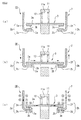
- the movable contact 3 In a condition in which the movable iron core 6 is in the current interruption position, the movable contact 3 is brought into contact with the bottom portion of the insertion hole 11a of the contact holder 11 by the contact spring 12, as shown in (a) of Fig. 2 . In this condition, the movable contact portions 3b and 3c formed one on each end side of the conductive plate portion 3a of the movable contact 3 are separated upward from the fixed contact portions 2a and 2b of the fixed contact 2, and the contact device CD is in a current interruption condition.
- a large current in the order of, for example, several hundred to one thousand several hundred amperes input from, for example, the external connection terminal 2i of the fixed contact 2 connected to a direct current power supply (not shown) is supplied to the movable contact portion 3b of the movable contact 3 through the outer side conductor plate portion 2e, inner side conductor plate portion 2c, and fixed contact portion 2a.
- the large current supplied to the movable contact portion 3b is supplied to the fixed contact portion 2b through the conductive plate portion 3a and movable contact portion 3c.
- the large current supplied to the fixed contact portion 2b is supplied to the inner side conductor plate portion 2d, outer side conductor plate portion 2f, and external connection terminal 2j, and a current conduction path through which the current is supplied to an external load is formed.
- the fixed contacts 2 are such that as the L-shaped conductive plate portions 2g and 2h are formed by the inner side conductor plate portions 2c and 2d and outer side conductor plate portions 2e and 2f, as shown in Fig. 2 , by the heretofore described current path being formed, magnetic fluxes generated by the current flowing through the outer conductor plate portions 2e and 2f are added to the magnetic flux on the upper side of the movable contact 3, thus increasing the magnetic flux density, compared with when only the movable contact 3 exists.
- the movable contact 3 is directly opposite to the inner side conductor plate portions 2c and 2d of the fixed contacts 2, and is opposite to the outer side conductor portions 2e and 2f of the fixed contacts 2 across the side surface plate of the upper case 1a.
- the electromagnetic contactor is configured as shown in Fig. 3 .
- 50 is an electromagnetic contactor, and the electromagnetic contactor 50 has an exterior insulation container 51 made of, for example, synthetic resin.
- the exterior insulation container 51 is configured of a lower case 52 configured of a bottomed cylindrical body whose upper end face is opened and an upper case 53 configured of a bottomed cylindrical body, mounted on the upper end face of the lower case 52, whose lower end portion is opened.
- a contact device 100 in which is disposed a contact mechanism and an electromagnet unit 200 which drives the contact device 100 are housed in the exterior insulating container 51 in such a way that the electromagnet unit 200 is disposed on the bottom plate of the lower case 52.
- the contact device 100 has a contact housing case 102 which houses a contact mechanism 101, as seen by referring to Fig. 4 too.
- the contact housing case 102 is formed into a tub-shaped body by integrally molding a rectangular cylindrical portion 102a and a top plate portion 102b closing the upper end of the rectangular cylindrical portion 102a from, for example, ceramic or synthetic resin.
- Ametal foil is formed on the open end face side of the tub-shaped body by a metalizing process, and a metal connecting member 304 is seal joined to the metal foil, thus configuring the contact housing case 102. Further, the connecting member 304 of the contact housing case 102 is seal joined to an upper magnetic yoke 210 to be described hereafter.
- the contact mechanism 101 includes a pair of fixed contacts 111 and 112 disposed fixed to their respective left and right side plate portions of the contact housing case 102 and a movable contact 130 disposed so as to be able to come into contact, from above, and out of contact with the fixed contacts 111 and 112.
- Each of the pair of fixed contacts 111 and 112 is such that an L-shaped conductor portion 119 is formed of an inner side conductor plate portion 117 fixed passing through the corresponding one of the left and right side plate portions of the rectangular cylindrical portion 102a of the contact housing case 102 and an outer side conductor plate portion 118 connected to an end portion of the inner side conductor plate portion 117 on the outer peripheral surface side of the contact housing case 102 and at least extending in a direction in which the movable contact moves away.
- the upper end portion of the outer side conductor plate portion 118 of the L-shaped conductor portion 119 is extended to the top plate portion 102b of the contact housing case 102, and the upper end of the outer side conductor plate portion 118 is bent along the top plate portion 102b, thus forming a fixed conductor portion 120 opposite to the movable contact 130.
- An external connection terminal 121 is formed at the inner side end of the fixed conductor portion 120.
- the pair of fixed contacts 111 and 112 are configured in a C-shape such that the extended end portion of the movable contact 130 is enclosed by the L-shaped conductor portion 119 and the fixed conductor portion 120 connected to the upper end of the outer side conductor plate portion 118.
- the inner side conductor plate portion 117 and outer side conductor plate portion 118 are fixed by, for example, brazing.
- the inner side conductor plate portion 117 and outer side conductor plate portion 118 may be fixed, not only by brazing, but by welding.
- contact portions 117a wherein the inner side end portions of the inner side conductor plate portions 117 of the fixed contacts 111 and 112 face the movable contact 130 extension direction end portions from below are formed.
- the movable contact 130 is disposed so as to face the contact portions 117a of the fixed contacts 111 and 112 from above.
- the movable contact 130 is formed of a conductive plate portion extending in a direction crossing a direction in which the movable contact 130 is movable.
- the movable contact 130 is supported by a connecting shaft 131 fixed in a movable plunger 215 of the electromagnet unit 200, to be described hereafter.
- the movable contact 130 is such that a central portion thereof in the vicinity of the connecting shaft 131 protrudes downward, whereby a depressed portion 132 is formed, and a through hole 133 into which to insert the connecting shaft 131 is formed in the depressed portion 132.
- a flange portion 131a protruding outward is formed at the upper end of the connecting shaft 131.
- the connecting shaft 131 is inserted from the lower end side thereof into a contact spring 134, and then inserted into the through hole 133 of the movable contact 130, thus bringing the upper end of the contact spring 134 into abutment with the flange portion 131a, and the movable contact 130 is positioned using, for example, a C-ring 135 so as to obtain a predetermined biasing force from the contact spring 134.
- the movable contact 130 in a released condition, takes on a condition in which the contact portions at either end thereof and the contact portions 117a of the inner side conductor plate portions 117 of the L-shaped conductor portions 119 of the fixed contacts 111 and 112 are out of contact with each other while maintaining a predetermined interval. Also, the movable contact 130 is set so that, in a closed position, the contact portions at either end thereof come into contact with the contact portions 117a of the inner side conductor plate portions 117 of the L-shaped conductor portions 119 of the fixed contacts 111 and 112 at a predetermined contact pressure applied by the contact spring 134.
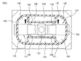
- magnet housing cylindrical bodies 141 and 142 are formed one in each of positions on the contact housing case 102 inner peripheral surfaces opposite to their respective side surfaces of the movable contact 130, as shown in Fig. 4 .
- Arc extinguishing permanent magnets 143 and 144 are inserted and fixed in the magnet housing cylindrical bodies 141 and 142 respectively.
- the arc extinguishing permanent magnets 143 and 144 are magnetized in a thickness direction so that the mutually opposing magnetic pole faces thereof are N-poles. Also, the arc extinguishing permanent magnets 143 and 144 are set so that both left-right direction end portions thereof are slightly inward of positions in which are opposed the contact portions 117a of the fixed contacts 111 and 112 and the contact portions 130a of the movable contact 130, as shown in Fig. 4 . Further, two pairs of arc extinguishing spaces 145 and 146 are formed one pair on the left-right direction outer sides of each respective magnet housing cylindrical body 141 and 142.
- movable contact guide members 148 and 149 which limit turning of the movable contact 130 by making sliding contact with side edges of the magnet housing cylindrical bodies 141 and 142 toward either end of the movable contact 130, are formed protruding.
- the electromagnet unit 200 has a magnetic yoke 201 of a flattened U-shape in side view, and a cylindrical auxiliary yoke 203 is fixed to the central portion of a bottom plate portion 202 of the magnetic yoke 201.
- a spool 204 is disposed on the outer side of the cylindrical auxiliary yoke 203.
- the spool 204 is configured of a central cylindrical portion 205 in which the cylindrical auxiliary yoke 203 is inserted, a lower flange portion 206 protruding radially outward from the lower end portion of the central cylindrical portion 205, and an upper flange portion 207 protruding radially outward from slightly below the upper end of the central cylindrical portion 205. Further, an exciting coil 208 is wound in a housing space configured of the central cylindrical portion 205, lower flange portion 206, and upper flange portion 207.
- an upper magnetic yoke 210 is fixed between the upper ends forming the open end of the magnetic yoke 201.
- a through hole 210a opposite to the central cylindrical portion 205 of the spool 204 is formed in the central portion of the upper magnetic yoke 210.
- the movable plunger 215 is covered with a cap 230 made of a non-magnetic body and formed in a bottomed cylindrical shape, and a flange portion 231 formed at the open end of the cap 230 so as to extend radially outward is seal joined to the lower surface of the upper magnetic yoke 210.
- a hermetic receptacle wherein the contact housing case 102 and cap 230 are in communication via the through hole 210a of the upper magnetic yoke 210, is formed.
- an arc extinguishing gas such as a hydrogen gas, a nitrogen gas, a mixed gas of hydrogen and nitrogen, air, or SF 6 , is enclosed in the hermetic receptacle formed by the contact housing case 102 and cap 230.
- a permanent magnet 220 formed in an annular shape is fixed to the upper surface of the upper magnetic yoke 210 so as to enclose the peripheral flange portion 216 of the movable plunger 215.
- the permanent magnet 220 is magnetized in an up-down direction, that is, in a thickness direction, so that the upper end side is an N-pole while the lower end side is an S-pole.
- the peripheral flange portion 216 of the movable plunger 215 is brought into abutment with the lower surface of the auxiliary yoke 225.
- the shape of the permanent magnet 220 can also be formed in an annular shape, in other words, the external shape can be any shape as long as the inner peripheral surface is a cylindrical surface.
- the connecting shaft 131 which supports the movable contact 130 is screwed in the upper end face of the movable plunger 215.
- the movable plunger 215 is biased upward by the return spring 214, and takes on a released position in which the upper surface of the peripheral flange portion 216 abuts against the lower surface of the auxiliary yoke 225.
- the contact portions 130a of the movable contact 130 move upward away from the contact portions 117a of the fixed contacts 111 and 112, thus taking on a condition in which the current is interrupted.
- an external connection terminal plate 151 is connected to, for example, a power supply source which supplies a large current, while an external connection terminal plate 152 is connected to a load.
- the exciting coil 208 in the electromagnet unit 200 is in a non-energized state, wherein a released condition is attained in which no exciting force causing the movable plunger 215 to descend is being generated in the electromagnet unit 200.
- the movable plunger 215 is biased in an upward direction away from the upper magnetic yoke 210 by the return spring 214.
- a magnetic attractive force caused by the magnetic force of the permanent magnet 220 acts on the auxiliary yoke 225, to which the peripheral flange portion 216 of the movable plunger 215 is attracted. Because of this, the upper surface of the peripheral flange portion 216 of the movable plunger 215 is in abutment with the lower surface of the auxiliary yoke 225.
- the contact portions 130a of the contact mechanism 101 movable contact 130 connected to the movable plunger 215 via the connecting shaft 131 are separated by a predetermined distance upward from the contact portions 117a of the fixed contacts 111 and 112. In this condition, the current path between the fixed contacts 111 and 112 is in an interrupted condition, and the contact mechanism 101 is in an open condition.
- the movable plunger 215 descends promptly against the biasing force of the return spring 214 and the magnetic attractive force of the annular permanent magnet 220. By so doing, the descent of the movable plunger 215 is stopped by the lower surface of the peripheral flange portion 216 coming into abutment with the upper surface of the upper magnetic yoke 210.
- the movable plunger 215 By the movable plunger 215 descending in this way, the movable contact 130 connected to the movable plunger 215 via the connecting shaft 131 also descends, and the contact portions 130a of the movable contact 130 come into contact with the contact portions 117a of the fixed contacts 111 and 112 owing to the contact pressure of the contact spring 134.
- electromagnetic repulsion forces are generated between the fixed contacts 111 and 112 and the movable contact 130 in a direction such as to cause the movable contact 130 to open.
- each fixed contact 111 and 112 is such that a C-shaped portion 122 thereof is formed of the fixed conductor portion 120, outer side conductor plate portion 118, and inner side conductor plate portion 117, as shown in Fig. 3 , the current in the fixed conductor portion 120 and the current in the inner side conductor plate portion 117 and the movable contact 130 in contact therewith flow in opposite directions.
- the outer side conductor plate portions 118 and fixed conductor portions 120 are insulated from the movable contact 130 by the contact housing case 102. Because of this, as no conductor plate portion exists in a direction in which the movable contact 130 moves away from the inner side conductor plate portions 117 of the fixed contacts 112, arcs generated when the current is interrupted are generated only between the inner side conductor plate portions 117 of the fixed contacts 112 and the movable contact 130, meaning that there is no need to provide an arc barrier such as an insulator cover for preventing unexpected arc generation, and it is thus possible to more simplify the configuration of the contact device 100.
- an arc barrier such as an insulator cover for preventing unexpected arc generation
- the exciting force causing the movable plunger 215 to move downward in the electromagnet unit 200 stops, as a result of which the movable plunger 215 is raised by the biasing force of the return spring 214, and the magnetic attractive force of the annular permanent magnet 220 increases as the peripheral flange portion 216 nears the auxiliary yoke 225.
- the magnetic flux emanating from the N-pole of each arc extinguishing permanent magnet 143 and 144 crosses an arc generation portion of a portion in which are opposed the contact portion 117a of the fixed contact 111 and the contact portion 130a of the movable contact 130, from the inner side to the outer side in a longitudinal direction of the movable contact 130, and reaches the S-pole, whereby a magnetic field is formed.
- the magnetic flux crosses an arc generation portion of the contact portion 117a of the fixed contact 112 and the contact portion 130a of the movable contact 130, from the inner side to the outer side in the longitudinal direction of the movable contact 130, and reaches the S-pole, whereby a magnetic field is formed.
- the magnetic fluxes of the arc extinguishing magnets 143 and 144 both cross between the contact portion 117a of the fixed contact 111 and the contact portion 130a of the movable contact 130 and between the contact portion 117a of the fixed contact 112 and the contact portion 130a of the movable contact 130, in mutually opposite directions in the longitudinal direction of the movable contact 130.
- an arc generated between the contact portion 117a of the fixed contact 111 and the contact portion 130a of the movable contact 130 is greatly extended so as to pass from the side surface of the contact portion 117a of the fixed contact 111 through inside the arc extinguishing space 145, reaching the upper surface side of the movable contact 130, and is extinguished.
- a magnetic flux inclines to the lower side and upper side with respect to the orientation of the magnetic flux between the contact portion 117a of the fixed contact 111 and the contact portion 130a of the movable contact 130. Because of this, the arc extended to the arc extinguishing space 145 is further extended by the inclined magnetic flux in the direction of the corner of the arc extinguishing space 145, and it is possible to increase the arc length, and thus possible to obtain good interruption performance.
- the current I flows from the movable contact 130 side to the fixed contact 112 side between the contact portion 117a of the fixed contact 112 and the movable contact 130, and the orientation of the magnetic flux ⁇ is in a rightward direction from the inner side toward the outer side. Because of this, in accordance with Fleming's left-hand rule, a large Lorentz force acts toward the arc extinguishing space 145 side, perpendicular to the longitudinal direction of the movable contact 130 and perpendicular to the direction in which the movable contact 130 is movable toward and away from the contact portion 117a of the fixed contact 112.
- an arc generated between the contact portion 117a of the fixed contact 112 and the movable contact 130 is greatly extended so as to pass from the upper surface side of the movable contact 130 through inside the arc extinguishing space 145, reaching the side surface side of the fixed contact 112, and is extinguished.
- a magnetic flux inclines to the lower side and upper side with respect to the orientation of the magnetic flux between the contact portion 117a of the fixed contact 112 and the contact portion 130a of the movable contact 130. Because of this, the arc extended to the arc extinguishing space 145 is further extended by the inclined magnetic flux in the direction of the corner of the arc extinguishing space 145, and it is possible to increase the arc length, and thus possible to obtain good interruption performance.
- the contact device 100 is such that the outer side conductor plate portions 118 and fixed conductor portions 120, of the C-shaped portions 122 of the fixed contacts 111 and 112, are disposed outside the contact housing case 102, it is possible to reduce the height and width of the contact housing case 102 and thus reduce the size of the contact device 100.
- the arc extinguishing permanent magnets 143 and 144 are disposed on the inner peripheral surfaces, of the insulating cylindrical body 140 configuring the contact housing case 102, opposite to the side edges of the movable contact 130, it is possible to bring the arc extinguishing permanent magnets 143 and 144 near to the contact faces of the pair of fixed contacts 111 and 112 and the movable contact 130.
- the movable contact guide members 148 and 149 in sliding contact with the side edges of the movable contact are formed protruding in positions, on the permanent magnet housing cylindrical bodies 141 and 142 housing the arc extinguishing permanent magnets 143 and 144, opposite to the movable contact 130, it is possible to reliably prevent turning of the movable contact 130.
- the contact device CD according to the invention is applied to the electromagnetic contactor, but the invention not being limited to this, the contact device CD can be applied to any device such as a switch or a direct current relay.
- the invention it is possible to provide a contact device with which it is possible to suppress electromagnetic repulsion forces which cause a movable contact to open when current is conducted without increasing the size of the overall configuration, and an electromagnetic contactor using the contact device.
- Electromagnetic contactor 100 ... Contact device, 101 ... Contact mechanism, 102 ... Contact housing case, 102a ... Rectangular cylindrical portion, 102b ... Top plate portion, 111, 112 ... Fixed contact, 117 ... Inner side conductor plate portion, 118 ... Outer side conductor plate portion, 119 ... L-shaped conductor portion, 120 ... Fixed conductor portion, 121 ... External connection terminal, 122 ... C-shaped portion, 130 ... Movable contact, 130a ... Contact portion, 131 ... Connecting shaft, 132 ... Depressed portion, 134 ... Contact spring, 135 ... C-ring, 140 ...
- Insulating cylindrical body 141, 142 ... Magnet housing cylindrical body, 143, 144 ... Arc extinguishing permanent magnet, 145, 146 ... Arc extinguishing space, 200 ...
- Electromagnet unit 201 ... Magnetic yoke, 202 ... Bottom plate portion, 203 ... Cylindrical auxiliary yoke, 204 ... Spool, 208 ... Exciting coil, 210 ... Upper magnetic yoke, 210a ... Through hole, 214 ... Return spring, 215 ... Movable plunger, 216 ... Peripheral flange portion, 220 ... Permanent magnet, 225 ... Auxiliary yoke, 230 ... Cap
Landscapes
- Physics & Mathematics (AREA)
- Electromagnetism (AREA)
- Arc-Extinguishing Devices That Are Switches (AREA)
- Contacts (AREA)
Claims (5)
- Dispositif de contact, comprenant un mécanisme de contact comportant une paire de contacts (111, 112) fixes disposés en maintenant une distance déterminée à l'avance et un contact (130) mobile disposé de manière à pouvoir venir en contact et hors de contact avec la paire de contacts (111, 112) fixes, dans lequel
le contact (130) mobile a, dans une boîte de logement de contacts, une partie en forme de plaque conductrice s'étendant dans une direction croisant une direction dans laquelle le contact mobile est mobile, la boîte (102) de logement de contacts formant une partie d'un réceptacle hermétique, de manière à enfermer un gaz de blindage, et caractérisé en ce que
chacun de la paire de contacts (111, 112) fixes est tel qu'une partie (119) conductrice en forme de L, qui crée une force de Lorentz s'opposant à une force de répulsion électromagnétique créée dans un sens d'ouverture entre le contact (111, 112) fixe et le contact (130) mobile quand du courant y passe, est formée d'une partie (117) en forme de plaque conductrice du côté intérieur, dont une extrémité est opposée à une partie d'extrémité de la partie en forme de plaque conductrice du contact (130) mobile et dont l'autre partie d'extrémité s'étend, parallèlement à la plaque en forme de plaque conductrice, vers l'extérieur de la boîte de logement de contacts, et d'une partie (118) en forme de plaque conductrice du côté extérieur, reliée à une partie d'extrémité de la partie (117) formant plaque conductrice du côté intérieur à l'extérieur de la boîte de logement des contacts, qui s'étend au moins dans un sens dans lequel le contact (110) mobile s'éloigne. - Dispositif de contact suivant la revendication 1, caractérisé en ce que
la partie (118) formant plaque conductrice du côté extérieur est formée dans une forme en L d'une partie formant plaque latérale, reliée à la partie en forme de plaque conductrice du côté intérieur, qui s'étend vers une partie formant plaque de sommet de la boîte de logement de contacts, et d'une partie formant plaque fixe, qui s'étend le long de la surface extérieure de la partie formant plaque de sommet de la boîte de logement de contacts à partir de la partie formant plaque latérale, et une borne de connexion est reliée à la partie formant plaque fixe. - Dispositif de contact suivant la revendication 1 ou 2, caractérisé en ce que
la boîte de logement de contacts est en un matériau isolant. - Dispositif de contact suivant l'une quelconque des revendications 1 à 3, caractérisé en ce que
un gaz de blindage est enfermé dans la boîte de logement de contacts. - Contacteur électromagnétique comprenant le dispositif de contact suivant l'une quelconque des revendications 1 à 4, le contacteur électromagnétique étant caractérisé en ce que
le contact mobile est relié à un noyau de fer mobile d'un électroaimant de fonctionnement.
Applications Claiming Priority (2)
| Application Number | Priority Date | Filing Date | Title |
|---|---|---|---|
| JP2011223145A JP5856426B2 (ja) | 2011-10-07 | 2011-10-07 | 接点装置及びこれを使用した電磁接触器 |
| PCT/JP2012/006358 WO2013051263A1 (fr) | 2011-10-07 | 2012-10-03 | Dispositif de contact et contacteur magnétique le mettant en œuvre |
Publications (3)
| Publication Number | Publication Date |
|---|---|
| EP2765586A1 EP2765586A1 (fr) | 2014-08-13 |
| EP2765586A4 EP2765586A4 (fr) | 2015-07-08 |
| EP2765586B1 true EP2765586B1 (fr) | 2016-04-20 |
Family
ID=48043443
Family Applications (1)
| Application Number | Title | Priority Date | Filing Date |
|---|---|---|---|
| EP12838528.3A Not-in-force EP2765586B1 (fr) | 2011-10-07 | 2012-10-03 | Dispositif de contact et contacteur magnétique le mettant en oeuvre |
Country Status (6)
| Country | Link |
|---|---|
| US (1) | US9378914B2 (fr) |
| EP (1) | EP2765586B1 (fr) |
| JP (1) | JP5856426B2 (fr) |
| KR (1) | KR101890848B1 (fr) |
| CN (1) | CN103875052B (fr) |
| WO (1) | WO2013051263A1 (fr) |
Families Citing this family (26)
| Publication number | Priority date | Publication date | Assignee | Title |
|---|---|---|---|---|
| JP5856426B2 (ja) * | 2011-10-07 | 2016-02-09 | 富士電機株式会社 | 接点装置及びこれを使用した電磁接触器 |
| JP5793048B2 (ja) * | 2011-10-07 | 2015-10-14 | 富士電機株式会社 | 電磁接触器 |
| EP3044799B1 (fr) * | 2013-10-25 | 2019-04-24 | Siemens Aktiengesellschaft | Unité de séparateur avec entraînement électromagnétique |
| DE102014107950B4 (de) * | 2014-06-05 | 2022-02-03 | Wago Verwaltungsgesellschaft Mbh | Steckverbinderanordnung und Löseelement hierzu |
| JP6403476B2 (ja) | 2014-07-28 | 2018-10-10 | 富士通コンポーネント株式会社 | 電磁継電器 |
| CN104882335B (zh) * | 2015-03-31 | 2017-07-28 | 厦门宏发电力电器有限公司 | 一种磁钢错位分布的灭弧磁路及其直流继电器 |
| JP6631068B2 (ja) * | 2015-07-27 | 2020-01-15 | オムロン株式会社 | 接点機構およびこれを用いた電磁継電器 |
| US9530593B1 (en) * | 2015-08-19 | 2016-12-27 | Carling Technologies, Inc. | Electromagnetically assisted arc quench with pivoting permanent magnet |
| JP6705207B2 (ja) * | 2016-02-25 | 2020-06-03 | 富士電機機器制御株式会社 | 電磁接触器 |
| CN107204250A (zh) * | 2016-03-18 | 2017-09-26 | 比亚迪股份有限公司 | 继电器 |
| DE102016217434B4 (de) * | 2016-09-13 | 2023-11-16 | Siemens Aktiengesellschaft | Schütz oder Kompaktmotorabzweig mit einer elektromagnetischen Kontaktlastunterstützung |
| JP6260677B1 (ja) * | 2016-12-02 | 2018-01-17 | 富士電機機器制御株式会社 | 電磁接触器 |
| JP6907801B2 (ja) * | 2017-08-10 | 2021-07-21 | オムロン株式会社 | 電磁継電器 |
| JP2019036434A (ja) * | 2017-08-10 | 2019-03-07 | オムロン株式会社 | 接続ユニット |
| CN109427506B (zh) * | 2017-08-25 | 2020-11-20 | 佛山市顺德区美的电热电器制造有限公司 | 压力开关及电压力锅 |
| JP6743834B2 (ja) * | 2018-01-31 | 2020-08-19 | アンデン株式会社 | 電磁継電器 |
| DE102018207468B3 (de) * | 2018-05-15 | 2019-08-29 | Siemens Aktiengesellschaft | Schaltgerät mit einer reduzierten mechanischen Schlagbelastung bei Änderung des Betriebsmodus in den ausgeschalteten Zustand |
| JP7115137B2 (ja) | 2018-08-21 | 2022-08-09 | オムロン株式会社 | リレー |
| JP7115142B2 (ja) * | 2018-08-24 | 2022-08-09 | オムロン株式会社 | リレー |
| JP7142219B2 (ja) * | 2018-11-13 | 2022-09-27 | パナソニックIpマネジメント株式会社 | 接点装置及び電磁継電器 |
| JP2020092041A (ja) * | 2018-12-06 | 2020-06-11 | パナソニックIpマネジメント株式会社 | 電磁継電器 |
| CN109559940A (zh) * | 2018-12-24 | 2019-04-02 | 浙江宏舟新能源科技有限公司 | 一种方便动铁芯加工的高压直流继电器 |
| CN110335783A (zh) * | 2019-07-22 | 2019-10-15 | 浙江天继电气有限公司 | 一种用于直流接触器的引弧触头 |
| JP7423944B2 (ja) * | 2019-09-13 | 2024-01-30 | オムロン株式会社 | 電磁継電器 |
| CN112598942B (zh) * | 2020-12-29 | 2023-03-14 | 日照职业技术学院 | 一种便于操作的英语教学无线遥控移动教学装置 |
| JP7415965B2 (ja) * | 2021-01-22 | 2024-01-17 | 富士電機機器制御株式会社 | 密閉型電磁接触器 |
Family Cites Families (39)
| Publication number | Priority date | Publication date | Assignee | Title |
|---|---|---|---|---|
| FR1094778A (fr) * | 1953-04-21 | 1955-05-24 | ||
| LU36208A1 (fr) * | 1957-07-03 | |||
| FR1446838A (fr) * | 1964-09-12 | 1966-07-22 | Continental Elektro Ind Ag | Contacteur |
| US3436697A (en) * | 1966-09-21 | 1969-04-01 | Bliss Co | Electromagnetic load relay having an insulated barrier between contacts |
| US3419828A (en) * | 1966-12-13 | 1968-12-31 | Arrow Hart Inc | Means proportional to magnetic flux to bias electric switch contacts closed |
| US3651437A (en) * | 1971-03-19 | 1972-03-21 | Matsushita Electric Works Ltd | Electromagnetic contactor |
| JPH0750579B2 (ja) * | 1988-12-23 | 1995-05-31 | 松下電工株式会社 | 密封型接点装置 |
| JP2570248B2 (ja) * | 1991-11-28 | 1997-01-08 | 松下電工株式会社 | 封止接点装置 |
| IT1264164B1 (it) * | 1993-04-21 | 1996-09-17 | Sace Spa | Interruttore di bassa tensione in scatola isolante |
| JPH07182961A (ja) * | 1993-12-22 | 1995-07-21 | Fuji Electric Co Ltd | 電磁接触器の鉄心保持構造 |
| JP3321963B2 (ja) * | 1994-02-22 | 2002-09-09 | 株式会社デンソー | プランジャ型電磁継電器 |
| US5892194A (en) * | 1996-03-26 | 1999-04-06 | Matsushita Electric Works, Ltd. | Sealed contact device with contact gap adjustment capability |
| JP3411206B2 (ja) * | 1997-12-26 | 2003-05-26 | 三菱電機株式会社 | 接点開閉機器の消弧装置 |
| JP3391016B2 (ja) * | 1998-08-25 | 2003-03-31 | 富士電機株式会社 | 電磁接触器 |
| DZ2952A1 (fr) * | 1998-12-01 | 2004-03-15 | Schneider Electric Ind Sa | Conacteur électromécanique logeant dans un corps un électroaimant et un porte-contacts mobile. |
| DE60019912T2 (de) * | 1999-10-14 | 2006-01-12 | Matsushita Electric Works, Ltd., Kadoma | Kontaktvorrichtung |
| JP2001118450A (ja) * | 1999-10-14 | 2001-04-27 | Matsushita Electric Works Ltd | 接点装置 |
| JP2001210170A (ja) | 2000-01-24 | 2001-08-03 | Mitsubishi Electric Corp | 開閉器 |
| US6563409B2 (en) * | 2001-03-26 | 2003-05-13 | Klaus A. Gruner | Latching magnetic relay assembly |
| JP2004071512A (ja) * | 2002-08-09 | 2004-03-04 | Omron Corp | 開閉装置 |
| JP4375012B2 (ja) | 2003-12-22 | 2009-12-02 | オムロン株式会社 | 固定接点端子の支持構造 |
| CA2569064C (fr) * | 2005-03-28 | 2011-08-02 | Matsushita Electric Works, Ltd. | Dispositif de contacts |
| JP2006310251A (ja) | 2005-03-28 | 2006-11-09 | Matsushita Electric Works Ltd | リレー用導電バー及びこの製造方法 |
| CN100521027C (zh) * | 2006-07-03 | 2009-07-29 | 浙江正泰电器股份有限公司 | 气密式带有工作触头的低压电器及其无氧密封方法 |
| DE102007054958A1 (de) * | 2007-11-17 | 2009-06-04 | Moeller Gmbh | Schaltgerät für Gleichstrom-Anwendungen |
| US20090315653A1 (en) * | 2008-06-18 | 2009-12-24 | Fuji Electric Fa Components & Systems Co., Ltd | Electromagnet device and electromagnetic contactor |
| JP5163318B2 (ja) * | 2008-06-30 | 2013-03-13 | オムロン株式会社 | 電磁石装置 |
| JP5206157B2 (ja) * | 2008-06-30 | 2013-06-12 | オムロン株式会社 | 電磁継電器 |
| JP2012028253A (ja) * | 2010-07-27 | 2012-02-09 | Fuji Electric Fa Components & Systems Co Ltd | 接点機構及びこれを使用した電磁接触器 |
| JP5134657B2 (ja) * | 2010-07-27 | 2013-01-30 | 富士電機機器制御株式会社 | 接点機構及びこれを使用した電磁接触器 |
| JP2012038684A (ja) * | 2010-08-11 | 2012-02-23 | Fuji Electric Fa Components & Systems Co Ltd | 接点装置及びこれを使用した電磁開閉器 |
| JP5385877B2 (ja) * | 2010-08-31 | 2014-01-08 | 富士電機機器制御株式会社 | 電磁開閉器 |
| JP5767508B2 (ja) * | 2011-05-19 | 2015-08-19 | 富士電機株式会社 | 電磁接触器 |
| JP5689741B2 (ja) * | 2011-05-19 | 2015-03-25 | 富士電機株式会社 | 電磁接触器 |
| JP5778989B2 (ja) * | 2011-05-19 | 2015-09-16 | 富士電機機器制御株式会社 | 電磁接触器 |
| JP5809443B2 (ja) * | 2011-05-19 | 2015-11-10 | 富士電機株式会社 | 接点機構及びこれを使用した電磁接触器 |
| JP5856426B2 (ja) * | 2011-10-07 | 2016-02-09 | 富士電機株式会社 | 接点装置及びこれを使用した電磁接触器 |
| JP5793048B2 (ja) * | 2011-10-07 | 2015-10-14 | 富士電機株式会社 | 電磁接触器 |
| JP7050579B2 (ja) | 2018-06-01 | 2022-04-08 | 旭化成建材株式会社 | フェノール樹脂発泡体積層板及びその製造方法 |
-
2011
- 2011-10-07 JP JP2011223145A patent/JP5856426B2/ja active Active
-
2012
- 2012-10-03 KR KR1020147008799A patent/KR101890848B1/ko active IP Right Grant
- 2012-10-03 EP EP12838528.3A patent/EP2765586B1/fr not_active Not-in-force
- 2012-10-03 CN CN201280049701.3A patent/CN103875052B/zh active Active
- 2012-10-03 US US14/344,821 patent/US9378914B2/en not_active Expired - Fee Related
- 2012-10-03 WO PCT/JP2012/006358 patent/WO2013051263A1/fr active Application Filing
Also Published As
| Publication number | Publication date |
|---|---|
| EP2765586A1 (fr) | 2014-08-13 |
| CN103875052A (zh) | 2014-06-18 |
| US9378914B2 (en) | 2016-06-28 |
| KR20140074916A (ko) | 2014-06-18 |
| JP2013084425A (ja) | 2013-05-09 |
| KR101890848B1 (ko) | 2018-08-22 |
| WO2013051263A1 (fr) | 2013-04-11 |
| EP2765586A4 (fr) | 2015-07-08 |
| US20150048908A1 (en) | 2015-02-19 |
| JP5856426B2 (ja) | 2016-02-09 |
| CN103875052B (zh) | 2017-05-10 |
Similar Documents
| Publication | Publication Date | Title |
|---|---|---|
| EP2765586B1 (fr) | Dispositif de contact et contacteur magnétique le mettant en oeuvre | |
| US8816801B2 (en) | Contact mechanism and electromagnetic contactor using the same | |
| EP2711965B1 (fr) | Contacteur électromagnétique | |
| US9373467B2 (en) | Electromagnetic contactor | |
| US9117611B2 (en) | Electromagnetic contactor | |
| US9653222B2 (en) | Contact device, and electromagnetic switch in which the contact device is used | |
| EP2765588B1 (fr) | Contacteur électromagnétique | |
| KR101750137B1 (ko) | 접점 기구 및 이것을 사용한 전자 접촉기 | |
| US9564279B2 (en) | Electromagnetic switch having magnetic yoke with slits | |
| EP2711957B1 (fr) | Contacteur électromagnétique | |
| US9202652B2 (en) | Electromagnetic contactor | |
| EP3748664A1 (fr) | Contacteur électromagnétique | |
| US9589739B2 (en) | Electromagnetic contactor |
Legal Events
| Date | Code | Title | Description |
|---|---|---|---|
| PUAI | Public reference made under article 153(3) epc to a published international application that has entered the european phase |
Free format text: ORIGINAL CODE: 0009012 |
|
| 17P | Request for examination filed |
Effective date: 20140507 |
|
| AK | Designated contracting states |
Kind code of ref document: A1 Designated state(s): AL AT BE BG CH CY CZ DE DK EE ES FI FR GB GR HR HU IE IS IT LI LT LU LV MC MK MT NL NO PL PT RO RS SE SI SK SM TR |
|
| DAX | Request for extension of the european patent (deleted) | ||
| REG | Reference to a national code |
Ref country code: DE Ref legal event code: R079 Ref document number: 602012017483 Country of ref document: DE Free format text: PREVIOUS MAIN CLASS: H01H0050000000 Ipc: H01H0050540000 |
|
| RA4 | Supplementary search report drawn up and despatched (corrected) |
Effective date: 20150610 |
|
| RIC1 | Information provided on ipc code assigned before grant |
Ipc: H01H 50/14 20060101ALI20150603BHEP Ipc: H01H 50/54 20060101AFI20150603BHEP Ipc: H01H 1/54 20060101ALI20150603BHEP Ipc: H01H 1/66 20060101ALI20150603BHEP Ipc: H01H 9/44 20060101ALI20150603BHEP Ipc: H01H 51/22 20060101ALI20150603BHEP |
|
| GRAP | Despatch of communication of intention to grant a patent |
Free format text: ORIGINAL CODE: EPIDOSNIGR1 |
|
| INTG | Intention to grant announced |
Effective date: 20160108 |
|
| GRAS | Grant fee paid |
Free format text: ORIGINAL CODE: EPIDOSNIGR3 |
|
| GRAA | (expected) grant |
Free format text: ORIGINAL CODE: 0009210 |
|
| AK | Designated contracting states |
Kind code of ref document: B1 Designated state(s): AL AT BE BG CH CY CZ DE DK EE ES FI FR GB GR HR HU IE IS IT LI LT LU LV MC MK MT NL NO PL PT RO RS SE SI SK SM TR |
|
| REG | Reference to a national code |
Ref country code: GB Ref legal event code: FG4D |
|
| REG | Reference to a national code |
Ref country code: CH Ref legal event code: EP |
|
| REG | Reference to a national code |
Ref country code: AT Ref legal event code: REF Ref document number: 793239 Country of ref document: AT Kind code of ref document: T Effective date: 20160515 |
|
| REG | Reference to a national code |
Ref country code: IE Ref legal event code: FG4D |
|
| REG | Reference to a national code |
Ref country code: DE Ref legal event code: R096 Ref document number: 602012017483 Country of ref document: DE |
|
| REG | Reference to a national code |
Ref country code: FR Ref legal event code: PLFP Year of fee payment: 5 |
|
| REG | Reference to a national code |
Ref country code: LT Ref legal event code: MG4D |
|
| REG | Reference to a national code |
Ref country code: AT Ref legal event code: MK05 Ref document number: 793239 Country of ref document: AT Kind code of ref document: T Effective date: 20160420 |
|
| REG | Reference to a national code |
Ref country code: NL Ref legal event code: MP Effective date: 20160420 |
|
| PG25 | Lapsed in a contracting state [announced via postgrant information from national office to epo] |
Ref country code: NL Free format text: LAPSE BECAUSE OF FAILURE TO SUBMIT A TRANSLATION OF THE DESCRIPTION OR TO PAY THE FEE WITHIN THE PRESCRIBED TIME-LIMIT Effective date: 20160420 Ref country code: FI Free format text: LAPSE BECAUSE OF FAILURE TO SUBMIT A TRANSLATION OF THE DESCRIPTION OR TO PAY THE FEE WITHIN THE PRESCRIBED TIME-LIMIT Effective date: 20160420 Ref country code: NO Free format text: LAPSE BECAUSE OF FAILURE TO SUBMIT A TRANSLATION OF THE DESCRIPTION OR TO PAY THE FEE WITHIN THE PRESCRIBED TIME-LIMIT Effective date: 20160720 Ref country code: LT Free format text: LAPSE BECAUSE OF FAILURE TO SUBMIT A TRANSLATION OF THE DESCRIPTION OR TO PAY THE FEE WITHIN THE PRESCRIBED TIME-LIMIT Effective date: 20160420 Ref country code: PL Free format text: LAPSE BECAUSE OF FAILURE TO SUBMIT A TRANSLATION OF THE DESCRIPTION OR TO PAY THE FEE WITHIN THE PRESCRIBED TIME-LIMIT Effective date: 20160420 |
|
| PG25 | Lapsed in a contracting state [announced via postgrant information from national office to epo] |
Ref country code: RS Free format text: LAPSE BECAUSE OF FAILURE TO SUBMIT A TRANSLATION OF THE DESCRIPTION OR TO PAY THE FEE WITHIN THE PRESCRIBED TIME-LIMIT Effective date: 20160420 Ref country code: ES Free format text: LAPSE BECAUSE OF FAILURE TO SUBMIT A TRANSLATION OF THE DESCRIPTION OR TO PAY THE FEE WITHIN THE PRESCRIBED TIME-LIMIT Effective date: 20160420 Ref country code: HR Free format text: LAPSE BECAUSE OF FAILURE TO SUBMIT A TRANSLATION OF THE DESCRIPTION OR TO PAY THE FEE WITHIN THE PRESCRIBED TIME-LIMIT Effective date: 20160420 Ref country code: GR Free format text: LAPSE BECAUSE OF FAILURE TO SUBMIT A TRANSLATION OF THE DESCRIPTION OR TO PAY THE FEE WITHIN THE PRESCRIBED TIME-LIMIT Effective date: 20160721 Ref country code: SE Free format text: LAPSE BECAUSE OF FAILURE TO SUBMIT A TRANSLATION OF THE DESCRIPTION OR TO PAY THE FEE WITHIN THE PRESCRIBED TIME-LIMIT Effective date: 20160420 Ref country code: LV Free format text: LAPSE BECAUSE OF FAILURE TO SUBMIT A TRANSLATION OF THE DESCRIPTION OR TO PAY THE FEE WITHIN THE PRESCRIBED TIME-LIMIT Effective date: 20160420 Ref country code: PT Free format text: LAPSE BECAUSE OF FAILURE TO SUBMIT A TRANSLATION OF THE DESCRIPTION OR TO PAY THE FEE WITHIN THE PRESCRIBED TIME-LIMIT Effective date: 20160822 Ref country code: AT Free format text: LAPSE BECAUSE OF FAILURE TO SUBMIT A TRANSLATION OF THE DESCRIPTION OR TO PAY THE FEE WITHIN THE PRESCRIBED TIME-LIMIT Effective date: 20160420 |
|
| PGFP | Annual fee paid to national office [announced via postgrant information from national office to epo] |
Ref country code: FR Payment date: 20160812 Year of fee payment: 5 |
|
| PG25 | Lapsed in a contracting state [announced via postgrant information from national office to epo] |
Ref country code: IT Free format text: LAPSE BECAUSE OF FAILURE TO SUBMIT A TRANSLATION OF THE DESCRIPTION OR TO PAY THE FEE WITHIN THE PRESCRIBED TIME-LIMIT Effective date: 20160420 Ref country code: BE Free format text: LAPSE BECAUSE OF FAILURE TO SUBMIT A TRANSLATION OF THE DESCRIPTION OR TO PAY THE FEE WITHIN THE PRESCRIBED TIME-LIMIT Effective date: 20160420 |
|
| REG | Reference to a national code |
Ref country code: DE Ref legal event code: R097 Ref document number: 602012017483 Country of ref document: DE |
|
| PG25 | Lapsed in a contracting state [announced via postgrant information from national office to epo] |
Ref country code: RO Free format text: LAPSE BECAUSE OF FAILURE TO SUBMIT A TRANSLATION OF THE DESCRIPTION OR TO PAY THE FEE WITHIN THE PRESCRIBED TIME-LIMIT Effective date: 20160420 Ref country code: CZ Free format text: LAPSE BECAUSE OF FAILURE TO SUBMIT A TRANSLATION OF THE DESCRIPTION OR TO PAY THE FEE WITHIN THE PRESCRIBED TIME-LIMIT Effective date: 20160420 Ref country code: DK Free format text: LAPSE BECAUSE OF FAILURE TO SUBMIT A TRANSLATION OF THE DESCRIPTION OR TO PAY THE FEE WITHIN THE PRESCRIBED TIME-LIMIT Effective date: 20160420 Ref country code: EE Free format text: LAPSE BECAUSE OF FAILURE TO SUBMIT A TRANSLATION OF THE DESCRIPTION OR TO PAY THE FEE WITHIN THE PRESCRIBED TIME-LIMIT Effective date: 20160420 Ref country code: SK Free format text: LAPSE BECAUSE OF FAILURE TO SUBMIT A TRANSLATION OF THE DESCRIPTION OR TO PAY THE FEE WITHIN THE PRESCRIBED TIME-LIMIT Effective date: 20160420 |
|
| PGFP | Annual fee paid to national office [announced via postgrant information from national office to epo] |
Ref country code: DE Payment date: 20161013 Year of fee payment: 5 |
|
| PLBE | No opposition filed within time limit |
Free format text: ORIGINAL CODE: 0009261 |
|
| STAA | Information on the status of an ep patent application or granted ep patent |
Free format text: STATUS: NO OPPOSITION FILED WITHIN TIME LIMIT |
|
| PG25 | Lapsed in a contracting state [announced via postgrant information from national office to epo] |
Ref country code: SM Free format text: LAPSE BECAUSE OF FAILURE TO SUBMIT A TRANSLATION OF THE DESCRIPTION OR TO PAY THE FEE WITHIN THE PRESCRIBED TIME-LIMIT Effective date: 20160420 |
|
| 26N | No opposition filed |
Effective date: 20170123 |
|
| PG25 | Lapsed in a contracting state [announced via postgrant information from national office to epo] |
Ref country code: SI Free format text: LAPSE BECAUSE OF FAILURE TO SUBMIT A TRANSLATION OF THE DESCRIPTION OR TO PAY THE FEE WITHIN THE PRESCRIBED TIME-LIMIT Effective date: 20160420 |
|
| REG | Reference to a national code |
Ref country code: CH Ref legal event code: PL |
|
| GBPC | Gb: european patent ceased through non-payment of renewal fee |
Effective date: 20161003 |
|
| REG | Reference to a national code |
Ref country code: IE Ref legal event code: MM4A |
|
| PG25 | Lapsed in a contracting state [announced via postgrant information from national office to epo] |
Ref country code: CH Free format text: LAPSE BECAUSE OF NON-PAYMENT OF DUE FEES Effective date: 20161031 Ref country code: GB Free format text: LAPSE BECAUSE OF NON-PAYMENT OF DUE FEES Effective date: 20161003 Ref country code: LI Free format text: LAPSE BECAUSE OF NON-PAYMENT OF DUE FEES Effective date: 20161031 |
|
| PG25 | Lapsed in a contracting state [announced via postgrant information from national office to epo] |
Ref country code: LU Free format text: LAPSE BECAUSE OF NON-PAYMENT OF DUE FEES Effective date: 20161003 |
|
| PG25 | Lapsed in a contracting state [announced via postgrant information from national office to epo] |
Ref country code: IE Free format text: LAPSE BECAUSE OF NON-PAYMENT OF DUE FEES Effective date: 20161003 |
|
| REG | Reference to a national code |
Ref country code: DE Ref legal event code: R119 Ref document number: 602012017483 Country of ref document: DE |
|
| PG25 | Lapsed in a contracting state [announced via postgrant information from national office to epo] |
Ref country code: HU Free format text: LAPSE BECAUSE OF FAILURE TO SUBMIT A TRANSLATION OF THE DESCRIPTION OR TO PAY THE FEE WITHIN THE PRESCRIBED TIME-LIMIT; INVALID AB INITIO Effective date: 20121003 |
|
| PG25 | Lapsed in a contracting state [announced via postgrant information from national office to epo] |
Ref country code: IS Free format text: LAPSE BECAUSE OF FAILURE TO SUBMIT A TRANSLATION OF THE DESCRIPTION OR TO PAY THE FEE WITHIN THE PRESCRIBED TIME-LIMIT Effective date: 20160420 Ref country code: MT Free format text: LAPSE BECAUSE OF NON-PAYMENT OF DUE FEES Effective date: 20161031 Ref country code: MC Free format text: LAPSE BECAUSE OF FAILURE TO SUBMIT A TRANSLATION OF THE DESCRIPTION OR TO PAY THE FEE WITHIN THE PRESCRIBED TIME-LIMIT Effective date: 20160420 Ref country code: CY Free format text: LAPSE BECAUSE OF FAILURE TO SUBMIT A TRANSLATION OF THE DESCRIPTION OR TO PAY THE FEE WITHIN THE PRESCRIBED TIME-LIMIT Effective date: 20160420 Ref country code: MK Free format text: LAPSE BECAUSE OF FAILURE TO SUBMIT A TRANSLATION OF THE DESCRIPTION OR TO PAY THE FEE WITHIN THE PRESCRIBED TIME-LIMIT Effective date: 20160420 |
|
| REG | Reference to a national code |
Ref country code: FR Ref legal event code: ST Effective date: 20180629 |
|
| PG25 | Lapsed in a contracting state [announced via postgrant information from national office to epo] |
Ref country code: BG Free format text: LAPSE BECAUSE OF FAILURE TO SUBMIT A TRANSLATION OF THE DESCRIPTION OR TO PAY THE FEE WITHIN THE PRESCRIBED TIME-LIMIT Effective date: 20160420 Ref country code: DE Free format text: LAPSE BECAUSE OF NON-PAYMENT OF DUE FEES Effective date: 20180501 |
|
| PG25 | Lapsed in a contracting state [announced via postgrant information from national office to epo] |
Ref country code: FR Free format text: LAPSE BECAUSE OF NON-PAYMENT OF DUE FEES Effective date: 20171031 |
|
| PG25 | Lapsed in a contracting state [announced via postgrant information from national office to epo] |
Ref country code: AL Free format text: LAPSE BECAUSE OF FAILURE TO SUBMIT A TRANSLATION OF THE DESCRIPTION OR TO PAY THE FEE WITHIN THE PRESCRIBED TIME-LIMIT Effective date: 20160420 Ref country code: TR Free format text: LAPSE BECAUSE OF FAILURE TO SUBMIT A TRANSLATION OF THE DESCRIPTION OR TO PAY THE FEE WITHIN THE PRESCRIBED TIME-LIMIT Effective date: 20160420 |