EP2762427A2 - Vorrichtung zum Wenden eines Gegenstandes - Google Patents
Vorrichtung zum Wenden eines Gegenstandes Download PDFInfo
- Publication number
- EP2762427A2 EP2762427A2 EP20140154027 EP14154027A EP2762427A2 EP 2762427 A2 EP2762427 A2 EP 2762427A2 EP 20140154027 EP20140154027 EP 20140154027 EP 14154027 A EP14154027 A EP 14154027A EP 2762427 A2 EP2762427 A2 EP 2762427A2
- Authority
- EP
- European Patent Office
- Prior art keywords
- transport
- elements
- drive
- frame
- transport elements
- Prior art date
- Legal status (The legal status is an assumption and is not a legal conclusion. Google has not performed a legal analysis and makes no representation as to the accuracy of the status listed.)
- Granted
Links
- 230000033001 locomotion Effects 0.000 claims description 29
- 230000005540 biological transmission Effects 0.000 claims description 19
- 239000006096 absorbing agent Substances 0.000 claims description 11
- 230000035939 shock Effects 0.000 claims description 11
- 230000000694 effects Effects 0.000 claims description 7
- 238000007599 discharging Methods 0.000 claims description 2
- 239000000463 material Substances 0.000 description 3
- 125000006850 spacer group Chemical group 0.000 description 3
- 229910000831 Steel Inorganic materials 0.000 description 2
- 238000005265 energy consumption Methods 0.000 description 2
- 238000004519 manufacturing process Methods 0.000 description 2
- 239000010959 steel Substances 0.000 description 2
- 230000001419 dependent effect Effects 0.000 description 1
- 238000000034 method Methods 0.000 description 1
Images



Classifications
-
- B—PERFORMING OPERATIONS; TRANSPORTING
- B65—CONVEYING; PACKING; STORING; HANDLING THIN OR FILAMENTARY MATERIAL
- B65G—TRANSPORT OR STORAGE DEVICES, e.g. CONVEYORS FOR LOADING OR TIPPING, SHOP CONVEYOR SYSTEMS OR PNEUMATIC TUBE CONVEYORS
- B65G47/00—Article or material-handling devices associated with conveyors; Methods employing such devices
- B65G47/22—Devices influencing the relative position or the attitude of articles during transit by conveyors
- B65G47/24—Devices influencing the relative position or the attitude of articles during transit by conveyors orientating the articles
- B65G47/248—Devices influencing the relative position or the attitude of articles during transit by conveyors orientating the articles by turning over or inverting them
- B65G47/252—Devices influencing the relative position or the attitude of articles during transit by conveyors orientating the articles by turning over or inverting them about an axis substantially perpendicular to the conveying direction
Definitions
- the invention relates to a device for turning an object, in particular a packet of stacked bags.
- Devices for turning objects are used in transporting and palletizing packages of stacked bags. It sometimes happens that the bags are not flat against each other and the packages therefore sink together in the middle. This may for example be the case when the bags have folded bottoms or valves at their ends. In order to still obtain a possible flat surface when palletizing such packages, it is therefore sometimes necessary to turn these packages.
- the packets are clamped and turned between two height-adjustable transport plates.
- the frame elements are rotated by a drum drive and thus turn the transport plates.
- the drum drive engages only from one side on the frame to set only one of the frame elements in motion.
- the frame elements must therefore be connected by at least one torsionally rigid connecting element, which makes it possible to transmit the rotational movement of the drive-side frame member to the second frame member, which faces away from the rotary drive. It has been found to be a disadvantage that when rotating the frame members, the transport plates can easily deflect due to their inertia from the guide rail, which is remote from the rotary drive, and that the transport plates can even fall off the frame.
- a device for turning an object which is designed with a holding device for receiving, turning and dispensing of the object and a rotating device for turning the holding device.
- the holding device has two transport elements, which can clamp the object, wherein the transport elements can be turned by means of the rotating device.
- the rotating device is formed with two frame elements which enclose the transport elements on both sides. On the frame members guide rails are provided, in which the transport elements are arranged to be movable.
- the DE 199 31 145 A1 provides a drum drive to rotate one of the frame members. It could be disadvantageous that the frame elements must be connected by heavy and large elements in order to transmit the rotational movement evenly to the transport elements. In addition, it could be disadvantageous that during the rotational movement, the transport elements can deflect out of the guide rails and the object can fall out.
- the invention is therefore based on the object to provide an improved device for turning an object, in particular a package of stacked bags, which overcomes the above-mentioned disadvantages.
- the device should have a simple structure, require little components and the cost of materials Reduce.
- the object of the present invention is achieved by all features of claim 1. In the dependent claims possible embodiments of the invention are described.
- the invention provides an apparatus for turning an object, in particular a stacked bag package, comprising a holding device for receiving, turning and discharging the object, which has two height-adjustable transport elements for conveying the object, and a rotating device for rotating the transport elements about one stationary axis of rotation is carried out, which has a rotatable frame for fixing the transport elements on both sides, wherein the transport elements are movably mounted on the frame, and wherein the rotating device has a rotary drive which drives the frame on both sides.
- the frame can be driven simultaneously from two sides by a rotary drive on which the transport elements are mounted.
- a stable rotational movement of the transport elements can be realized.
- the rotational speed of the frame can be increased with the same power of the rotary drive.
- the rotating device according to the invention also requires no heavy torsionally rigid connecting elements more to stabilize the frame and to transmit the rotational motion evenly along along the transport elements. The transport elements can therefore be reliably held on both sides of the frame during the rotational movement.
- the device can not only be made more stable but also lighter, so that the energy consumption for turning the object can be reduced with increasing rotational speed.
- the holding device may have a transport drive for driving the transport elements and consequently for conveying the object.
- the transport drive can be fixedly attached to a housing of the device or mitbewegbar on the frame.
- the transport drive allows in addition to the rotary drive, that the object can be conveyed in a transport direction, while the rotary drive can be provided exclusively for turning the transport elements.
- the device according to the invention can be designed as a structural unit be flexibly positioned at a suitable location of a transport device to allow the object to be turned.
- the transport elements can be connected to one another with an adjusting mechanism and / or moved toward one another in a clamping direction in order to clamp the object for turning.
- the adjustment mechanism may comprise a pneumatic cylinder, wherein in particular the pneumatic cylinder may have quick exhaust valves.
- Pneumatic drives advantageously allow high operating speeds, at the same time an elastic and resilient drive behavior can be achieved.
- the adjusting mechanism according to the invention is therefore particularly suitable to be arranged on moving objects, so that the adjusting mechanism can be attached directly to the transport elements.
- objects of different sizes and heights can be reliably received by the adjusting mechanism according to the invention.
- the compressed air supply can be advantageously provided by a flexible hose, which can be guided for example by the axis of rotation of the device to the pneumatic cylinder.
- the invention may further provide that the rotating device may have a shock absorber to dampen the movement of the transport elements to each other, and in particular that the shock absorber may be rotatably mounted on the frame.
- the shock absorbers can protect the object from the excessive impact with the transport elements.
- the shock absorbers can be moved with the frame and thus with the transport elements, so that in any rotational position of the transport elements of the object can be reliably and yet dampened clamped.
- the transport elements may be designed in the form of roller conveyors.
- each transport element can have at least two transport rollers, which can be in operative connection with one another by means of a connecting belt, in particular a flat belt, tooth belt or V-ribbed belt.
- roller conveyors can be flexibly formed and the spatial Specifications as well as the size of the object.
- transport elements can be adapted to the weight of the object to be transported.
- the rollers may be formed of different materials such as steel or plastic depending on the weight of the object to be transported.
- the recording and the transportability of the roller conveyors can be adjusted by different widths of the transport rollers.
- the connection to the transport drive can advantageously be made only on one of the transport rollers. If only one transport roller is set in motion, all other transport rollers are automatically moved, since the movement is transmitted via the connecting belts.
- the transport rollers can be connected via a transmission with the transport drive, which may have a flat belt and a drive wheel with a corresponding friction lining.
- the transport elements may be designed in the form of a conveyor track with a conveyor belt and two deflection rollers.
- the transport drive can act on one of the deflection rollers.
- the transport drive can be arranged in one of the transport or deflection rollers.
- the transport elements can advantageously on both sides have fastening elements which enclose the transport rollers and serve for fastening the transport elements on the frame.
- the transport elements may be formed with the transport rollers as a common component.
- the attachment of the transport rollers can be simplified on the frame, wherein the fastening elements can be slidably mounted on the frame.
- the rotary drive can have a motor, in particular a drum motor.
- the frame may have two turntables to enclose the transport elements on both sides.
- the drum drive can transmit the drive effect of the motor via a flat, toothed or V-ribbed belt to the frame.
- the drum drive can advantageously set heavy objects with a high translation force in motion and generate a high torque. Consequently for example, the device may provide an improved rotational speed of the article and allow rapid transport of the article.
- Each turntable may according to the invention comprise a guide rail which can cooperate with sliding elements, which can be arranged on both sides of the transport elements.
- the guide rails can be used to attach the transport elements to the turntables, and on the other hand to store the transport elements movable on the turntables. Then the transport elements can be rotated not only with the turntables but at the same time moved up and from each other to clamp the object for turning and release it for further transport.
- the rotary drive can have at least one chamfer, which can connect the rotary disks, but which no longer serve to transmit the rotary motion between the rotary disks and need not have a large weight.
- the spacer is advantageously only for holding the relative position of the rotating disks to each other.
- the invention can reduce the weight of the spacer, thereby reducing the overall weight of the device, so that the energy required to rotate the device can be reduced.
- the rotary drive can have two gear elements which are rotatable about a rotary shaft by means of a rotary drive in order to drive both rotary disks at the same time.
- the gear elements can be positioned directly under the turntables and have the same distance to each other as the turntables.
- it is particularly advantageous that the turntables can be driven simultaneously by only one rotary drive by means of the two gear elements.
- the rotational speed of the frame can be increased at the same rotational drive power.
- the rotating device requires no more heavy connecting elements to connect the turntables and to transmit the rotational movement of the drive-side hub to the second hub, which faces away from the rotary drive.
- the transport elements can therefore be reliably attached to the frame and stored in the guide rails, at the same time a high rotational speed of the holding device can be ensured.
- the rotary drive can have two transmission elements, in particular two flat, toothed or V-ribbed belts, in order to transmit the effect of the transmission elements to the rotary disks.
- the transmission elements advantageously ensure that the effect of the rotary drive can be transmitted equal to both hubs.
- the device can be made more stable and yet lighter, whereby the energy consumption for turning the object can be optimized with increasing rotational speed.
- the transport drive can be moved with the frame and thus with the transport elements, so that when turning the frame, the transport elements can be further driven and the object can be further moved in a transport direction. This can be ensured that the transport of the object does not interrupt during the turning.
- the transport speed can be increased and the performance of the device can be improved.
- the transport drive can be rotated, the operative connection between the transport drive and the transport elements must not be interrupted.
- the transport drive can be rigidly fixed to the frame, since there is no need to cushion the movement of the transport elements on the transport drive.
- the operative connection between the transport drive and the transport elements can advantageously be maintained during the turning and transporting of the article. Therefore, the operative connection can be made in a simple manner and with the aid of simple components such as toothed belts and turning wheels or rollers.
- a slip ring may be provided on the axis of rotation to feed the transport drive, in particular the drive motor.
- the invention is further based on the idea that the transport drive for each transport element may have its own drive unit. This can be the advantage be achieved that both transport elements regardless of the rotational position for transporting the object can be designed. Since both transport elements can participate in the transport of the article, the transport speed can be increased, while the required drive power for transport can be reduced. Moreover, it is advantageous that the drive units can be made smaller and lighter.
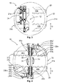
- the FIG. 1 shows an apparatus for turning an object, as known from the prior art, and the FIG. 2 the device 10 according to the invention, wherein below the devices and their differences will be discussed in detail.
- the conventional device comprises similar to the device 10 according to the invention a holding device 20 for receiving, turning and dispensing of the article, the two height-adjustable 13 transport elements 21 a, 21 b for conveying the article and a transport drive 22 for driving the transport elements 21 a, 21 b has , And a rotating device 30 for rotating the transport elements 21 a, 21 b about a stationary axis of rotation 12, the closer from the FIGS. 7 and 8 is described.
- the invention relates to the new transport drive 22, as shown in the FIG. 2 , which in contrast to the conventional transport drive 22 of the FIG. 1 with a frame 31 of the rotating device 30, which in the FIGS. 7 and 8 is shown, and thus with the transport elements 21 a, 21 b is movable.
- the inventive idea is that when turning the transport elements 21 a, 21 b they can be driven further and the object can move further in a transport direction 11, in the FIG. 6 is shown.
- the advantage of the invention lies in the fact that the transport of the article is not interrupted even during the turning of the transport elements 21 a, 21 b.
- the transport drive 22 according to the invention is rigidly attached to the frame 31, as shown in the FIGS. 4 and 5 ,
- the transport drive 22 of the conventional device is the FIG. 1 fixedly arranged on a housing, not shown, of the device.
- the conventional transport drive 22 when moving the transport elements 21 a, 21 b apart again, the movement of the transport elements 21 a, 21 b to transport drive 22 at least partially cushion until the operative connection between the transport elements 21 a, 21 b and the transport drive 22nd is made.
- the stationary transport drive 22 is normally mounted resiliently on the housing of the device.
- the transport drive 22 according to the invention can be fixedly attached to the rotating device 30 (s. FIGS. 3 and 4 ), Since the operative connection between the transport drive 22 according to the invention and the transport elements 21 a, 21 b does not interrupt even during turning.
- the transfer of the conventional Transport drive 22 on the transport elements 21 a, 21 b is produced by means of a drive wheel with a special friction lining and a corresponding flat belt on the side of the transport elements 21 a, 21 b, the transport elements 21 a, 21 b in motion by means of a wheel gear.
- FIG. 2 shows an embodiment of the invention, in which the transport drive 22 according to the invention for each transport element 21 a, 21 b has its own drive unit 22 a, 22 b.
- the two drive units 22a, 22b serve to ensure that both transport elements 21a, 21b can continue to transport the object regardless of their rotational position.
- the transport speed can be increased considerably, while at the same time the required power of the drive units 22a, 22b can be reduced. Therefore, smaller and lighter drive units 22a, 22b can be used.
- the FIG. 3 shows an adjustment mechanism 24 which serves to connect the transport elements 21 a, 21 b together and to move in a vertical clamping direction 13 to each other to clamp the object for turning.
- the adjusting mechanism 24 according to the invention is designed as a pneumatic cylinder 24.
- the pneumatic cylinder 24 in this case has quick exhaust valves to quickly move the transport elements 21a, 21b and still achieve an elastic and resilient pinching of the object.
- the adjusting mechanism 24 is mounted according to the invention directly to the transport elements 21 a, 21 b.
- the compressed air supply can be advantageously provided by a flexible hose, which can be performed for example by the stationary axis of rotation 12 to the adjusting mechanism 24.
- a flexible hose which can be performed for example by the stationary axis of rotation 12 to the adjusting mechanism 24.
- Shock absorbers 34 are shown, which serve to dampen the movement of the transport elements 21a, 21b to each other and to protect the article at pinching 21 a, 21 b against mechanical effects by the transport elements 21 a, 21 b.
- the shock absorbers 34 are rotatably mounted in the illustrated embodiment of the rotating device 30, wherein during the turning, the shock absorber 34 with the transport elements 21a, 21b moves become.
- the FIG. 5 shows a further advantageous embodiment of the invention with a slip ring 36 which is arranged on the axis of rotation 12 in order to energize the drive motors 60a, 60b of the rotary drive units 22a, 22b.
- the FIG. 6 shows an embodiment of the transport elements 21a, 21b according to the invention, which are designed in the form of roller conveyors.
- the roller conveyor comprises a plurality of transport rollers 41, 42, wherein the number of transport rollers 41, 42 and their size and weight can be adapted to the dimensions of the object.
- the transport rollers 41, 42 may be formed according to the invention of various materials such as steel or plastic, depending on how heavy and large the object to be transported is.
- Each two adjacent transport rollers 41, 42 are each connected to a connecting belt 43, in particular rotationally fixed to each other to transmit the rotational movement of a transport roller 41, 42 to the other.
- the connecting belt 43 may be formed, for example, as a flat, toothed or V-ribbed belt. According to the invention, only one of the transport rollers 41, 42 is set in motion (s. Figures 2 and 4 ), through the connecting belt 43, the rotational movement is transmitted to all other transport rollers 41, 42.
- the transport elements 21 a, 21 b are, as shown in the FIGS. 2 to 5 , Rotatable from both end sides of fastening elements 40a, 40b, which enclose the transport rollers 41, 42 and also serve to fasten the transport elements 21 a, 21 b on the rotating device 30.
- the FIG. 4 shows that the fastening elements 40a, 40b are displaceably mounted on the frame 31 of the rotating device 30 along a guide rail 35.
- the frame 31 of the rotating device 30 has two rotors 31 a, 31 b, in more detail in FIG. 8 are shown.
- Each of the turntables 31 a, 31 b is formed with a guide rail 35, to store the transport elements 21 a, 21 b slidably from both end sides.
- Each guide rail 35 cooperates according to the invention with sliding elements 25a, 25b, which are arranged on the fastening elements 40a, 40b of the transport elements 21a, 21b.
- the transport elements 21a, 21b are not only rotated with the turntables 31a, 31b, but are also moved up and away from one another along the arrow 13, in order to clamp the object for turning and release it for further transport.
- the drive units 22a, 22b according to the invention each have a drive wheel 61a, 61b, which is driven by a respective drive motor 60a, 60b, and a deflection wheel 62a, 62b in order to control the action of the drive motor 60a, 60b on the corresponding transport element 21a, 21 b via a transmission wheel 63 a, 63 b to transmit.
- the drive units 22a, 22b according to the invention are articulated with a hinge in the deflection wheel 62a, 62b.
- the drive motor 60a, 60b is rigidly fastened to the frame 31, wherein the drive effect is transmitted to the transport elements 21a, 21b by the articulated drive units 22a, 22b, which are movably arranged on the frame 31. This ensures that during the clamping movement and during rotation of the object is moved further in the transport direction 11.
- the drive wheel 61 a, 61 b is rotatably attached to the corresponding hub 31 a, 31 b attached.
- the deflection wheel 62a, 62b is at least partially pulled along with the transport element 21a, 21b.
- the guide wheel 62a, 62b is freely movable according to the invention and is only in mechanical operative connection with the drive wheel 61a, 61b and the transmission wheel 63a, 63b.
- the drive wheel 61 a, 61 b, the guide wheel 62 a, 62 b and the transmission wheel 63 a, 63 b thereby form a kind of joint arrangement with two legs between the drive wheel 61 a, 61 b and the guide wheel 62 a, 62 b and between the guide wheel 62 a, 62 b and Transmission wheel 63a, 63b with the joint in the deflection wheel 62a, 62b.
- the drive units 22a, 22b are in the joint on the guide wheel 62a, 62b when moving the transport elements 21a, 21b to each other and opened or closed.
- the drive effect is still reliably from the drive wheel 61 a, 61 b to the deflection wheel 62 a, 62 b and the guide wheel 62 a, 62 b transmitted to the transmission wheel 63 a, 63 b. This ensures that the transport elements 21 a, 21 b are in any position on the guide rail 35 in operative connection with the corresponding transport drive 60a, 60b and the transport rollers 41, 42 transport the object.
- the transmission wheel 63a, 63b engage directly on a transport roller 41, 42.
- This transport roller 41, 42 then transmits the rotational movement to an adjacent transport roller 41, 42 by means of the connecting element 43 and thus sets the respective roller conveyor in motion.
- one of the transport rollers 41, 42 serves as part the drive unit 22a, 22b.
- the device 10 according to the invention fewer components and transmission elements, which is based on the Figures 1 and 2 is apparent.
- Each inventive drive wheel 61 a, 61 b, as shown in the Figures 2 . 4 and 5 is connected by means of a first drive belt 64a, 64b with the deflection wheel 62a, 62b and the deflection wheel 62a, 62b by means of a second drive belt 65a, 65b with the transmission wheel 63a, 63b.
- the first and the second drive belt 64, 65 may be formed for example in the form of a flat, toothed or V-ribbed belt.
- the drive belt 64, 65 remain permanently on the wheels 62, 63, 64 abut and hold the mechanical operative connection from the drive motor 60 a, 60 b to the transport elements 21 a, 21 b during the whole process and regardless of the position of the transport elements 21 a, 21 b upright on the frame 31. Since the transport elements 21 a, 21 b are driven during the turning, the transport speed of the article can be significantly increased and the performance of the device can be improved. For this purpose, the invention provides that the drive units 22a, 22b are turned during the turning with the transport elements 21a, 21b.
- FIGS. 7 and 8 each show a conventional 32 and a rotary device according to the invention 30. Both devices have a rotary drive 32 with a motor 50 which is designed as a drum motor.
- the conventional rotary drive 32 of FIG. 7 acts only on one side of the holding device 20, wherein the rotating device 30 of the FIG. 7 has only one turntable 31 and only one transmission element 53 in order to transmit the driving action of the motor 50 to the holding device 20 only from one side.
- the rotating device 30 according to the invention is formed with a rotatable frame 31 having two rotors 31 a, 31 b, to enclose the holding device 20 from two sides.
- the particular advantage of the invention consists in the fact that the rotary drive 32 according to the invention drives the frame 31 on both sides.
- the rotary drive 32 engages the frame 31 at two turntables 31 a, 31 b, which enclose the transport elements 21 a, 21 b on both sides.
- the rotary drive 32 has two gear elements 51 a, 51 b, which are rotatably mounted about a rotary shaft 52 which extends parallel to the axis of rotation 12 of the transport elements 21 a, 21 b.
- the rotation shaft 52 is rotated by the motor 50 driven and transmits the rotational movement to the two gear elements 51a, 51b.
- the gear elements 51a, 51b are in turn connected to the two rotary disks 31a, 31b and drive them via two transmission elements 53a, 53b, for example in the form of flat, toothed or V-ribbed belts about the axis of rotation 12.
- both turntables 31 a, 31 b are actively driven by only the rotary drive 32 in order to transmit the rotational movement uniformly to the holding device 20.
- the rotation of the transport elements 21 a, 21 b can be stabilized at the same power.
- the transport elements 21 a, 21 b at a higher rotational speed reliable at the turntables 31 a, 31 b are kept as in the device of FIG.
- the conventional rotary device of FIG. 7 requires heavy fasteners 33 to transmit the rotational movement of only one side to the side remote from the rotary drive side of the transport elements 21 a, 21 b.
- the FIG. 7 the risk that the transport elements 21 a, 21 b from the connection points with the frame 30, which are remote from the drive, can deflect due to their inertia.
- the device 10 of the invention FIG. 8 on the other hand requires no torsion-resistant connecting elements 33, since the rotational movement is transmitted from two sides to the transport elements 21 a, 21 b.
- the transport elements 21 a, 21 b are therefore reliably held on the frame 31 during the rotational movement, at the same time a high rotational speed of the holding device 20 can be achieved.
- FIGS. 2 to 6 and 8th can be combined with each other, it being conceivable that the device 10 of the FIG. 8 can be performed with a transport drive 22, as in the FIGS. 2 to 5 is shown, and vice versa.
- the transport drive 22 can have a separate drive unit 22a, 22b for each transport element 21a, 21b. It is also conceivable that instead of a roller conveyor of the FIG. 6 a conveyor track can be used.
- the rotary drive 32 for each turntable 31 a, 31 b may have its own drive unit.
Landscapes
- Engineering & Computer Science (AREA)
- Mechanical Engineering (AREA)
- Specific Conveyance Elements (AREA)
- Rollers For Roller Conveyors For Transfer (AREA)
Abstract
Description
- Die Erfindung betrifft eine Vorrichtung zum Wenden eines Gegenstandes, insbesondere eines Paketes aus gestapelten Säcken.
- Vorrichtungen zum Wenden von Gegenständen werden beim Transportieren und Palettieren von Paketen aus gestapelten Säcken verwendet. Dabei kommt es manchmal vor, dass die Säcke einander nicht flächig anliegen und die Pakete deswegen in der Mitte zusammensinken. Dies kann beispielsweise dann der Fall sein, wenn die Säcke an ihren Enden gefaltete Böden oder Ventile aufweisen. Um dennoch eine möglich ebene Fläche beim Palettieren von solchen Paketen zu erhalten, ist es daher manchmal notwendig, diese Pakete zu wenden.
- In herkömmlichen Vorrichtungen werden die Pakete zwischen zwei höhenverstellbaren Transportplatten eingeklemmt und gewendet. Dabei werden die Transportplatten an einem Gestell zwischen zwei Gestellelementen angeordnet und verschiebbar, meistens mittels Führungsschienen an diesen Gestellelementen befestigt. Die Gestellelemente werden durch einen Trommelantrieb gedreht und wenden somit die Transportplatten. Üblicherweise greift der Trommelantrieb lediglich von einer Seite am Gestell ein, um nur eines der Gestellelemente in Bewegung zu setzen. Die Gestellelemente müssen daher durch mindestens ein torsionssteifes Verbindungselement verbunden werden, welches es ermöglicht, die Rotationsbewegung vom antriebsseitigen Gestellelement an das zweite Gestellelement zu übertragen, welches dem Drehantrieb abgewandt ist. Dabei hat sich als Nachteil herausgestellt, dass beim Drehen der Gestellelemente die Transportplatten aufgrund ihrer Trägheit leicht aus der Führungsschiene ausschlagen können, die von dem Drehantrieb entfernt ist, und dass die Transportplatten gar vom Gestell abfallen können.
- Aus der
DE 199 31 145 A1 ist eine Vorrichtung zum Wenden eines Gegenstandes bekannt, die mit einer Haltevorrichtung zum Aufnehmen, Wenden und Abgeben des Gegenstandes und einer Drehvorrichtung zum Wenden der Haltevorrichtung ausgeführt ist. Die Haltevorrichtung weist dabei zwei Transportelemente auf, die den Gegenstand einklemmen können, wobei die Transportelemente mittels der Drehvorrichtung gewendet werden können. Die Drehvorrichtung ist mit zwei Gestellelementen ausgebildet, die die Transportelemente beidseitig umschließen. An den Gestellelementen sind Führungsschienen vorgesehen, in denen die Transportelemente bewegbar angeordnet sind. Auch dieDE 199 31 145 A1 sieht einen Trommelantrieb vor, um eines der Gestellelemente zu drehen. Dabei könnte es nachteilig sein, dass die Gestellelemente durch schwere und große Elemente verbunden werden müssen, um die Drehbewegung gleichmäßig an die Transportelemente zu übertragen. Außerdem könnte es von Nachteil sein, dass während der Drehbewegung die Transportelemente aus den Führungsschienen ausschlagen können und der Gegenstand herausfallen kann. - Der Erfindung liegt daher die Aufgabe zugrunde, eine verbesserte Vorrichtung zum Wenden eines Gegenstandes, insbesondere eines Paketes aus gestapelten Säcken bereitzustellen, die die oben genannten Nachteile überwindet. Insbesondere ist es die Aufgabe der Erfindung eine Vorrichtung zum Wenden eines Gegenstandes zu schaffen, die ein zuverlässiges und stabiles Wenden des Gegenstandes ermöglicht. Die Vorrichtung soll einen einfachen Aufbau aufweisen, wenig Bauteile erfordern und den Materialaufwand vermindern. Die Aufgabe der vorliegenden Erfindung wird durch sämtliche Merkmale des Patentanspruches 1 gelöst. In den abhängigen Patentansprüchen sind mögliche Ausgestaltungen der Erfindung beschrieben.
- Die Erfindung sieht eine Vorrichtung zum Wenden eines Gegenstandes, insbesondere eines Paketes aus gestapelten Säcken vor, die mit einer Haltevorrichtung zum Aufnehmen, Wenden und Abgeben des Gegenstandes, die zwei höhenverstellbare Transportelemente zum Befördern des Gegenstandes aufweist, und einer Drehvorrichtung zum Drehen der Transportelemente um eine ortsfeste Drehachse ausgeführt ist, die ein drehbares Gestell zum beidseitigen Befestigen der Transportelemente aufweist, wobei die Transportelemente bewegbar am Gestell befestigt sind, und wobei die Drehvorrichtung einen Drehantrieb aufweist, welcher das Gestell beidseitig antreibt.
- Im Gegensatz zu einem herkömmlichen, einseitigen Drehantrieb ist es besonders vorteilhaft, dass das Gestell gleichzeitig von zwei Seiten durch einen Drehantrieb angetrieben werden kann, an welchem die Transportelemente befestigt sind. So kann eine stabile Drehbewegung der Transportelemente realisiert werden. Dabei kann die Drehgeschwindigkeit des Gestells bei gleicher Leistung des Drehantriebes erhöht werden. Die erfindungsgemäße Drehvorrichtung benötigt außerdem keine schweren torsionssteifen Verbindungselemente mehr, um das Gestell zu stabilisieren und um die Rotationsbewegung gleichmäßig auf entlang der Transportelemente zu übertragen. Die Transportelemente können daher während der Drehbewegung zuverlässig an beiden Seiten am Gestell gehalten werden. Im Gegensatz zu einem einseitigen Drehantrieb kann die Vorrichtung nicht nur stabiler sondern auch leichter ausgebildet werden, sodass der Energieverbrauch zum Wenden des Gegenstandes bei steigender Drehgeschwindigkeit reduziert werden kann.
- Erfindungsgemäß kann die Haltevorrichtung einen Transportantrieb zum Antreiben der Transportelemente und folglich zum Befördern des Gegenstandes aufweisen. Der Transportantrieb kann dabei ortsfest an einem Gehäuse der Vorrichtung oder mitbewegbar am Gestell befestigt sein. Der Transportantrieb ermöglicht neben dem Drehantrieb, dass der Gegenstand in eine Transportrichtung befördert werden kann, während der Drehantrieb ausschließlich zum Wenden der Transportelemente vorgesehen sein kann. Vorteilhafterweise kann die erfindungsgemäße Vorrichtung als eine Baueinheit ausgeführt werden und flexibel an einem geeigneten Ort einer Transportvorrichtung positioniert werden, um das Wenden des Gegenstandes zu ermöglichen.
- Vorteilhafterweise können die Transportelemente mit einem Verstellmechanismus miteinander verbunden und/oder in eine Klemmrichtung aufeinander bewegt werden, um den Gegenstand zum Wenden einzuklemmen. Erfindungsgemäß kann der Verstellmechanismus einen Pneumatikzylinder aufweisen, wobei insbesondere der Pneumatikzylinder Schnellentlüftungsventile aufweisen kann. Pneumatische Antriebe erlauben vorteilhafterweise hohe Arbeitsgeschwindigkeiten, wobei gleichzeitig ein elastisches und nachgiebiges Antriebsverhalten erzielt werden kann. Der erfindungsgemäße Verstellmechanismus ist daher besonders geeignet, an bewegten Objekten angeordnet zu werden, sodass der Verstellmechanismus direkt an den Transportelementen befestigt werden kann. Weiterhin kann es von Vorteil sein, dass durch den erfindungsgemäßen Verstellmechanismus Gegenstände unterschiedlicher Größen und Höhen zuverlässig aufgenommen werden können. Die Druckluftzufuhr kann vorteilhafterweise durch einen flexiblen Schlauch bereitgestellt werden, welcher beispielsweise durch die Drehachse der Vorrichtung zum Pneumatikzylinder geführt werden kann.
- Die Erfindung kann weiterhin vorsehen, dass die Drehvorrichtung einen Stoßdämpfer aufweisen kann, um die Bewegung der Transportelemente aufeinander zu dämpfen, und dass insbesondere der Stoßdämpfer drehfest am Gestell befestigt sein kann. Insbesondere in modernen Vorrichtungen, die hohe Transport- und Drehgeschwindigkeiten aufweisen, können die Stoßdämpfer den Gegenstand vor dem zu starken Aufeinanderstoßen mit den Transportelementen schützen. Die Stoßdämpfer können dabei mit dem Gestell und somit mit den Transportelementen mitbewegt werden, sodass in jeder Drehposition der Transportelemente der Gegenstand zuverlässig und dennoch gedämpft eingeklemmt werden kann.
- Erfindungsgemäß können die Transportelemente in Form von Rollenbahnen ausgebildet sein. Ferner ist es denkbar, dass jedes Transportelement mindestens zwei Transportrollen aufweisen kann, welche mittels eines Verbindungsriemens, insbesondere eines Flach-, Zahn- oder Keilrippenriemens miteinander in Wirkverbindung stehen können. Vorteilhafterweise können Rollenbahnen flexibel ausgebildet werden und den räumlichen Vorgaben sowie der Größe des Gegenstandes angepasst werden. Außerdem ist es vorteilhaft, dass derartige Transportelemente an das Gewicht des zu transportierenden Gegenstandes angepasst werden können. Dabei können die Rollen aus unterschiedlichen Materialien wie Stahl oder Kunststoff in Abhängigkeit von dem Gewicht des zu transportierenden Gegenstandes ausgebildet werden. Auch kann die Aufnahme und die Transportfähigkeit der Rollenbahnen durch verschiedene Breiten der Transportrollen eingestellt werden. Zum Antrieb der Transportrollen, die jeweils in Paaren mittels eines Verbindungsriemens verbunden sein können, kann die Verbindung zum Transportantrieb vorteilhafterweise nur an einer der Transportrollen hergestellt werden. Wird nur eine Transportrolle in Bewegung versetzt, werden alle anderen Transportrollen automatisch mitbewegt, da die Bewegung über die Verbindungsriemen übertragen wird. Alternativ ist es denkbar, dass die Transportrollen über ein Getriebe mit dem Transportantrieb verbunden werden können, welches einen Flachriemen und ein Antriebsrad mit entsprechendem Reibbelag aufweisen kann. Alternativ können die Transportelemente in Form einer Förderbahn mit einem Förderband und zwei Umlenkrollen ausgebildet sein. Dabei kann der Transportantrieb an einer der Umlenkrollen angreifen. Alternativ oder zusätzlich kann vorgesehen sein, dass der Transportantrieb in einer der Transport- bzw. Umlenkrollen angeordnet werden kann.
- Die Transportelemente können vorteilhafterweise beidseitig Befestigungselemente aufweisen, die die Transportrollen umschließen und zum Befestigen der Transportelemente am Gestell dienen. So können die Transportelemente mit den Transportrollen als ein gemeinsames Bauteil ausgebildet sein. Dadurch kann die Befestigung der Transportrollen am Gestell vereinfacht werden, wobei die Befestigungselemente am Gestell verschiebbar gelagert werden können.
- Ferner sieht die Erfindung vor, dass der Drehantrieb einen Motor, insbesondere einen Trommelmotor aufweisen kann. Dabei kann das Gestell zwei Drehscheiben aufweisen, um die Transportelemente beidseitig zu umschließen. Der Trommelantrieb kann dabei die Antriebswirkung des Motors über einen Flach-, Zahn- oder Keilrippenriemen an das Gestell übertragen. Der Trommelantrieb kann vorteilhafterweise schwere Gegenstände mit einer hohen Übersetzungskraft in Bewegung setzen und ein hohes Drehmoment erzeugen. Somit kann die Vorrichtung eine verbesserte Drehgeschwindigkeit des Gegenstandes bereitstellen und eine schnelle Beförderung des Gegenstandes ermöglichen.
- Jede Drehscheibe kann erfindungsgemäß eine Führungsschiene aufweisen, die mit Gleitelementen zusammenwirken kann, die beidseitig an den Transportelementen angeordnet sein können. Vorteilhafterweise können die Führungsschienen dazu dienen, die Transportelemente an den Drehscheiben zu befestigen, und andererseits die Transportelemente aufeinander bewegbar an den Drehscheiben zu lagern. Dann können die Transportelemente nicht nur mit den Drehscheiben gedreht werden sondern gleichzeitig auf- und voneinander bewegt werden, um den Gegenstand zum Wenden einzuklemmen und zum weiteren Transport freizugeben.
- Der Drehantrieb kann erfindungsgemäß mindestens einen Anstandshalter aufweisen, der die Drehscheiben verbinden kann, der jedoch nicht mehr zur Übertragung der Drehbewegung zwischen den Drehscheiben dienen und kein großes Gewicht aufweisen muss. Der Abstandshalter dient vorteilhafterweise lediglich zum Halten der relativen Position der Drehscheiben zueinander. Vorteilhafterweise kann durch die Erfindung das Gewicht des Abstandshalters reduziert werden, wodurch die Vorrichtung insgesamt an Gewicht verliert, sodass die erforderliche Energie zum Drehen der Vorrichtung vermindert werden kann.
- Erfindungsgemäß kann der Drehantrieb zwei Getriebeelemente aufweisen, die um eine Drehwelle mittels eines Drehantriebes drehbar sind, um beide Drehscheiben gleichzeitig anzutreiben. Die Getriebeelemente können direkt unter den Drehscheiben positioniert werden und gleichen Abstand zu einander aufweisen wie die Drehscheiben. Im Gegensatz zu einem einseitigen Drehantrieb ist es besonders vorteilhaft, dass die Drehscheiben gleichzeitig durch nur einen Drehantrieb mittels der zwei Getriebeelemente angetrieben werden können. Dabei kann die Drehgeschwindigkeit des Gestells bei gleicher Drehantriebsleistung erhöht werden. Die Drehvorrichtung benötigt dabei keine schweren Verbindungselemente mehr, um die Drehscheiben zu verbinden und um die Rotationsbewegung von der antriebsseitigen Drehscheibe an die zweite Drehscheibe zu übertragen, welche dem Drehantrieb abgewandt ist. Die Transportelemente können daher zuverlässig am Gestell befestigt und in den Führungsschienen gelagert werden, wobei gleichzeitig eine hohe Drehgeschwindigkeit der Haltevorrichtung gewährleistet werden kann. Erfindungsgemäß kann der Drehantrieb zwei Übertragungselemente, insbesondere zwei Flach-, Zahn- oder Keilrippenriemen aufweisen, um die Wirkung der Getriebeelemente auf die Drehscheiben zu übertragen. Die Übertragungselemente sorgen vorteilhafterweise dazu, dass die Wirkung des Drehantriebes gleich an beiden Drehscheiben übertragen werden kann. Im Gegensatz zu einem einseitigen Drehantrieb kann die Vorrichtung stabiler und dennoch leichter ausgebildet werden, wobei der Energieverbrauch zum Wenden des Gegenstandes bei steigender Drehgeschwindigkeit optimiert werden kann.
- Nach einem besonderen Vorteil der Erfindung kann der Transportantrieb mit dem Gestell und somit mit den Transportelementen mitbewegt werden, sodass beim Wenden des Gestells, die Transportelemente weiter angetrieben werden können und der Gegenstand weiter in eine Transportrichtung bewegt werden kann. Damit kann sichergestellt werden, dass der Transport des Gegenstandes während des Wendens nicht unterbricht. Somit kann die Transportgeschwindigkeit erhöht und die Leistung der Vorrichtung verbessert werden. Insbesondere in modernen Betrieben mit einer dauerhaften Produktion, Beförderung und Palettierung von gestapelten Säcken ist es von erheblichem Vorteil, eine hohe Leistung zu gewährleisten, um den immer höheren Standarden zu entsprechen und eine gewinnbringende Produktionsgeschwindigkeit sicherzustellen. Da der Transportantrieb mitgedreht werden kann, muss die Wirkverbindung zwischen dem Transportantrieb und den Transportelementen nicht unterbrochen werden. Daher ergibt sich der Vorteil, dass der Transportantrieb starr am Gestell befestigt werden kann, da der Bedarf entfällt, die Bewegung der Transportelemente auf den Transportantrieb abzufedern. Die Wirkverbindung zwischen dem Transportantrieb und den Transportelementen kann vorteilhafterweise während des Wendens und des Transportierens des Gegenstandes aufrechterhalten werden. Deswegen kann die Wirkverbindung auf eine einfache Weise und mit Hilfe einfacher Bauteile wie Zahnriemen und Drehräder bzw. Rollen hergestellt werden.
- Vorteilhafterweise kann ein Schleifring an der Drehachse vorgesehen sein, um den Transportantrieb, insbesondere den Antriebsmotor zu speisen.
- Die Erfindung geht weiterhin von dem Gedanken aus, dass der Transportantrieb für jedes Transportelement eine eigene Antriebseinheit aufweisen kann. Dadurch kann der Vorteil erreicht werden, dass beide Transportelemente ungeachtet der Drehposition zum Transportieren des Gegenstandes ausgelegt sein können. Da beide Transportelemente am Transport des Gegenstandes teilnehmen können, kann die Transportgeschwindigkeit erhöht werden, wobei gleichzeitig die erforderliche Antriebsleistung für den Transport reduziert werden kann. Außerdem ist es von Vorteil, dass die Antriebseinheiten kleiner und leichter ausgeführt werden können.
- Weitere Vorteile, Merkmale und Einzelheiten der Erfindung ergeben sich aus der nachfolgenden Beschreibung, in der unter Bezugnahme auf die Zeichnungen mehrere Ausführungsbeispiele im Einzelnen beschrieben sind. Dabei können die in den Ansprüchen und in der Beschreibung erwähnten Merkmale jeweils einzeln für sich oder in beliebiger Kombination erfindungswesentlich sein. Es zeigen:
- Fig. 1
- eine schematische Darstellung einer herkömmlichen Vorrichtung zum Wenden eines Gegenstandes,
- Fig. 2
- eine schematische Darstellung einer erfindungsgemäßen Vorrichtung zum Wenden eines Gegenstandes,
- Fig. 3
- eine schematische Darstellung eines erfindungsgemäßen Verstellmechanismus,
- Fig. 4
- eine schematische Darstellung erfindungsgemäßer Stoßdämpfer,
- Fig. 5
- eine schematische Darstellung eines erfindungsgemäßen Schleifringes,
- Fig. 6
- eine schematische Darstellung eines erfindungsgemäßen Transportelementes,
- Fig. 7
- eine perspektivische Darstellung der herkömmlichen Vorrichtung zum Wenden eines Gegenstandes, und
- Fig. 8
- eine perspektivische Darstellung der erfindungsgemäßen Vorrichtung zum Wenden eines Gegenstandes.
- Die
Figur 1 zeigt eine Vorrichtung zum Wenden eines Gegenstandes, wie sie aus dem Stand der Technik bekannt ist, und dieFigur 2 die erfindungsgemäße Vorrichtung 10, wobei nachfolgend auf die Vorrichtungen und deren Unterschiede im Detail eingegangen wird. Die herkömmliche Vorrichtung umfasst ähnlich wie die erfindungsgemäße Vorrichtung 10 eine Haltevorrichtung 20 zum Aufnehmen, Wenden und Abgeben des Gegenstandes, die zwei höhenverstellbare 13 Transportelemente 21 a, 21 b zum Befördern des Gegenstandes und einen Transportantrieb 22 zum Antreiben der Transportelemente 21 a, 21 b aufweist, und eine Drehvorrichtung 30 zum Drehen der Transportelemente 21 a, 21 b um eine ortsfeste Drehachse 12, die näher anhand derFiguren 7 und 8 beschrieben wird. - Die Erfindung betrifft den neuen Transportantrieb 22, wie gezeigt in der
Figur 2 , der im Gegensatz zum herkömmlichen Transportantrieb 22 derFigur 1 mit einem Gestell 31 der Drehvorrichtung 30, die in denFiguren 7 und 8 gezeigt ist, und somit mit den Transportelementen 21 a, 21 b bewegbar ist. Der Erfindungsgedanke liegt dabei darin, dass beim Wenden der Transportelemente 21 a, 21 b sie weiter angetrieben werden können und der Gegenstand weiter in eine Transportrichtung 11 bewegen können, die in derFigur 6 gezeigt ist. Der Vorteil der Erfindung liegt dabei darin, dass der Transport des Gegenstandes auch während des Wendens der Transportelemente 21 a, 21 b nicht unterbrochen wird. - Der erfindungsgemäße Transportantrieb 22 ist starr am Gestell 31 befestigt, wie gezeigt in den
Figuren 4 und5 . Im Gegensatz dazu ist der Transportantrieb 22 der herkömmlichen Vorrichtung derFigur 1 ortsfest an einem nicht dargestellten Gehäuse der Vorrichtung angeordnet. Bei der Vorrichtung derFigur 1 werden nur die Transportelemente 21 a, 21 b in eine vertikale Richtung 13 aufeinander bewegt, um den Gegenstand einzuklemmen. Dabei muss der herkömmliche Transportantrieb 22 beim Bewegen der Transportelemente 21 a, 21 b wieder auseinander, die Bewegung der Transportelemente 21 a, 21 b zum Transportantrieb 22 zumindest zum Teil abfedern, bis die Wirkverbindung zwischen den Transportelementen 21 a, 21 b und dem Transportantrieb 22 hergestellt ist. Um dies zu erreichen, wird der ortsfeste Transportantrieb 22 normalerweise federnd am Gehäuse der Vorrichtung gelagert. Im Gegensatz zum Stand der Technik kann der erfindungsgemäße Transportantrieb 22 fest an der Drehvorrichtung 30 befestigt sein (s.Figuren 3 und 4 ), da die Wirkverbindung zwischen dem erfindungsgemäßen Transportantrieb 22 und den Transportelementen 21 a, 21 b auch während des Wendens nicht unterbricht. Die Wirkübertragung vom herkömmlichen Transportantrieb 22 auf die Transportelemente 21 a, 21 b wird mittels eines Antriebsrades mit einem speziellen Reibbelag und einem korrespondierenden Flachriemen auf der Seite der Transportelemente 21 a, 21 b hergestellt, der mittels eines Radgetriebes die Transportelemente 21 a, 21 b in Bewegung setzt. Im Gegensatz dazu kann die Wirkverbindung zwischen dem erfindungsgemäßen Transportantrieb 22 und den Transportelementen 21 a, 21 b auf eine einfache Weise und mittels einfacher sowie weniger Bauteile wie Flach-, Zahn- oder Keilrippenriemen 64, 65 hergestellt werden und während des Transportierens und Wendens des Gegenstandes aufrechterhalten bleiben. - Die
Figur 2 zeigt ein Ausführungsbeispiel der Erfindung, bei dem der erfindungsgemäße Transportantrieb 22 für jedes Transportelement 21 a, 21 b eine eigene Antriebseinheit 22a, 22b aufweist. Gemäß dem Ausführungsbeispiel dienen die zwei Antriebseinheiten 22a, 22b dazu, dass beide Transportelemente 21a, 21b ungeachtet deren Drehposition den Gegenstand weiter transportieren können. Dadurch kann die Transportgeschwindigkeit erheblich erhöht werden, wobei gleichzeitig die erforderliche Leistung der Antriebseinheiten 22a, 22b reduziert werden kann. Deswegen können kleinere und leichtere Antriebseinheiten 22a, 22b verwendet werden. - Die
Figur 3 zeigt einen Verstellmechanismus 24, der dazu dient, die Transportelemente 21 a, 21b miteinander zu verbinden und in einer vertikalen Klemmrichtung 13 aufeinander zu bewegen, um den Gegenstand zum Wenden einzuklemmen. Der erfindungsgemäße Verstellmechanismus 24 ist als ein Pneumatikzylinder 24 ausgebildet. Der Pneumatikzylinder 24 weist dabei Schnellentlüftungsventile auf, um die Transportelemente 21a, 21 b schnell zu bewegen und dennoch ein elastisches und nachgiebiges Einklemmen des Gegenstandes zu erzielen. Der Verstellmechanismus 24 ist gemäß der Erfindung direkt an den Transportelementen 21 a, 21 b befestigt. Die Druckluftzufuhr kann vorteilhafterweise durch einen flexiblen Schlauch bereitgestellt werden, der beispielsweise durch die ortsfeste Drehachse 12 zum Verstellmechanismus 24 geführt werden kann. In derFigur 4 sind Stoßdämpfer 34 gezeigt, die dazu dienen, die Bewegung der Transportelemente 21a, 21b aufeinander zu dämpfen und den Gegenstand bei Einklemmen 21 a, 21 b vor mechanischen Einwirkungen durch die Transportelemente 21 a, 21 b zu schützen. Die Stoßdämpfer 34 sind im dargestellten Ausführungsbeispiel drehfest an der Drehvorrichtung 30 befestigt, wobei während des Wendens die Stoßdämpfer 34 mit den Transportelementen 21a, 21b mitbewegt werden. DieFigur 5 zeigt eine weitere vorteilhafte Ausführungsform der Erfindung mit einem Schleifring 36, der an der Drehachse 12 angeordnet ist, um die Antriebsmotoren 60a, 60b der drehbaren Antriebseinheiten 22a, 22b mit Energie zu versorgen. - Die
Figur 6 zeigt ein Ausführungsbeispiel der erfindungsgemäßen Transportelemente 21a, 21 b, die in Form von Rollenbahnen ausgebildet sind. Die Rollenbahn umfasst mehrere Transportrollen 41, 42, wobei die Anzahl von Transportrollen 41, 42 sowie deren Größe und Gewicht an die Maße des Gegenstandes angepasst werden können. Die Transportrollen 41, 42 können erfindungsgemäß aus verschiedenen Materialien wie Stahl oder Kunststoff ausgebildet sein, je nachdem wie schwer und groß der zu transportierende Gegenstand ist. Jede zwei benachbarten Transportrollen 41, 42 sind mit jeweils einem Verbindungsriemen 43, insbesondere drehfest miteinander verbunden, um die Drehbewegung von einer Transportrolle 41, 42 zur der anderen zu übertragen. Der Verbindungsriemen 43 kann beispielsweise als ein Flach-, Zahn- oder Keilrippenriemen ausgebildet sein. Gemäß der Erfindung wird nur eine der Transportrollen 41, 42 in Bewegung gesetzt (s.Figuren 2 und4 ), durch die Verbindungsriemen 43 wird die Drehbewegung auf alle anderen Transportrollen 41, 42 übertragen. - Die Transportelemente 21 a, 21 b sind, wie gezeigt in den
Figuren 2 bis 5 , von beiden Endseiten drehbar an Befestigungselementen 40a, 40b angeordnet, die die Transportrollen 41, 42 umschließen und außerdem zum Befestigen der Transportelemente 21 a, 21 b an der Drehvorrichtung 30 dienen. DieFigur 4 zeigt, dass die Befestigungselemente 40a, 40b dabei am Gestell 31 der Drehvorrichtung 30 verschiebbar entlang einer Führungsschiene 35 gelagert sind. Das Gestell 31 der Drehvorrichtung 30 weist zwei Drehscheiben 31 a, 31 b auf, die ausführlicher inFigur 8 gezeigt sind. Jede der Drehscheiben 31 a, 31 b ist dabei mit einer Führungsschiene 35 ausgebildet, um die Transportelemente 21 a, 21 b von beiden Endseiten verschiebbar zu lagern. Jede Führungsschiene 35 wirkt erfindungsgemäß mit Gleitelementen 25a, 25b zusammen, die an den Befestigungselementen 40a, 40b der Transportelemente 21 a, 21 b angeordnet sind. Erfindungsgemäß werden die Transportelemente 21a, 21 b nicht nur mit den Drehscheiben 31 a, 31 b mitgedreht sondern gleichzeitig auf- und voneinander entlang des Pfeils 13 bewegt, um den Gegenstand zum Wenden einzuklemmen und zum weiteren Transport freizugeben. - Die erfindungsgemäßen Antriebseinheiten 22a, 22b weisen jeweils ein Antriebsrad 61 a, 61 b, das durch jeweils einen Antriebsmotor 60a, 60b angetrieben wird, und ein Umlenkrad 62a, 62b auf, um die Wirkung des Antriebsmotors 60a, 60b auf das entsprechende Transportelement 21 a, 21 b über ein Übertragungsrad 63a, 63b zu übertragen. Die Antriebseinheiten 22a, 22b sind erfindungsgemäß gelenkig mit einem Gelenk im Umlenkrad 62a, 62b ausgebildet. Der Antriebsmotor 60a, 60b ist starr am Gestell 31 befestig, wobei durch die gelenkigen Antriebseinheiten 22a, 22b die Antriebswirkung an Transportelemente 21 a, 21 b übertragen wird, die bewegbar am Gestell 31 angeordnet sind. Dadurch wird erreicht, dass während der Klemmbewegung sowie während des Drehens der Gegenstand weiter in die Transportrichtung 11 bewegt wird.
- Das Antriebsrad 61 a, 61 b ist dabei drehfest an der entsprechenden Drehscheibe 31 a, 31 b befestigt. Dagegen ist das Übertragungsrad 63a, 63b am Transportelement 21 a, 21 b befestigt und mit dem Transportelement 21 a, 21 b bewegbar. Dabei wird das Umlenkrad 62a, 62b zumindest zum Teil mit dem Transportelement 21 a, 21 b mitgezogen. Das Umlenkrad 62a, 62b ist erfindungsgemäß frei beweglich und steht nur mit dem Antriebsrad 61 a, 61 b und dem Übertragungsrad 63a, 63b in mechanischer Wirkverbindung. Das Antriebsrad 61 a, 61 b, das Umlenkrad 62a, 62b und das Übertragungsrad 63a, 63b bilden dabei eine Art Gelenkanordnung mit zwei Schenkeln zwischen dem Antriebsrad 61 a, 61 b und dem Umlenkrad 62a, 62b sowie zwischen dem Umlenkrad 62a, 62b und dem Übertragungsrad 63a, 63b mit dem Gelenk im Umlenkrad 62a, 62b. Die Antriebseinheiten 22a, 22b werden im Gelenk am Umlenkrad 62a, 62b beim Bewegen der Transportelemente 21a, 21 b zu- und voneinander geöffnet bzw. geschlossen. Die Antriebswirkung wird dabei dennoch zuverlässig vom Antriebsrad 61 a, 61 b zum Umlenkrad 62a, 62b und vom Umlenkrad 62a, 62b zum Übertragungsrad 63a, 63b übertragen. Damit wird erreicht, dass die Transportelemente 21 a, 21 b in jeder Position an der Führungsschiene 35 in Wirkverbindung mit dem entsprechenden Transportantrieb 60a, 60b stehen und die Transportrollen 41, 42 den Gegenstand transportieren.
- Erfindungsgemäß kann das Übertragungsrad 63a, 63b direkt an einer Transportrolle 41, 42 eingreifen. Diese Transportrolle 41, 42 überträgt dann die Drehbewegung an eine benachbarte Transportrolle 41, 42 mittels des Verbindungselementes 43 weiter und setzt so die jeweilige Rollenbahn in Bewegung. Somit dient eine der Transportrollen 41, 42 als Teil der Antriebseinheit 22a, 22b. Im Gegensatz zur herkömmlichen Vorrichtung der
Figur 1 erfordert die erfindungsgemäße Vorrichtung 10 weniger Bauteile und Getriebeelemente, was anhand derFiguren 1 und 2 ersichtlich ist. - Jedes erfindungsgemäße Antriebsrad 61 a, 61 b, wie gezeigt in den
Figuren 2 ,4 und5 ist mittels eines ersten Antriebsriemens 64a, 64b mit dem Umlenkrad 62a, 62b und das Umlenkrad 62a, 62b mittels eines zweiten Antriebsriemens 65a, 65b mit dem Übertragungsrad 63a, 63b verbunden. Der erste und der zweite Antriebsriemen 64, 65 können beispielsweise in Form eines Flach-, Zahn- oder Keilrippenriemens ausgebildet sein. Die Antriebsriemen 64, 65 bleiben permanent an den Rädern 62, 63, 64 anliegen und halten die mechanische Wirkverbindung vom Antriebsmotor 60a, 60b zu den Transportelementen 21 a, 21 b während des ganzen Prozesses und unabhängig von der Position der Transportelemente 21 a, 21 b am Gestell 31 aufrecht. Da die Transportelemente 21 a, 21 b auch während des Wendens angetrieben werden, kann die Transportgeschwindigkeit des Gegenstandes erheblich erhöht und die Leistung der Vorrichtung verbessert werden. Hierzu sieht die Erfindung vor, dass die Antriebseinheiten 22a, 22b während des Wendens mit den Transportelementen 21 a, 21 b mitgedreht werden. - Die
Figuren 7 und 8 zeigen jeweils eine herkömmliche 32 und eine erfindungsgemäße Drehvorrichtung 30. Beide Vorrichtungen weisen einen Drehantrieb 32 mit einem Motor 50 auf, der als ein Trommelmotor ausgebildet ist. Der herkömmliche Drehantrieb 32 derFigur 7 wirkt nur einseitig auf die Haltevorrichtung 20 ein, wobei die Drehvorrichtung 30 derFigur 7 nur eine Drehscheibe 31 und nur ein Übertragungselement 53 aufweist, um die Antriebswirkung des Motors 50 lediglich von einer Seite an die Haltevorrichtung 20 zu übertragen. Dagegen ist die erfindungsgemäße Drehvorrichtung 30 mit einem drehbaren Gestell 31 ausgebildet, das zwei Drehscheiben 31 a, 31 b aufweist, um die Haltevorrichtung 20 von zwei Seiten zu umschließen. Der besondere Vorteil der Erfindung besteht dabei darin, dass der erfindungsgemäße Drehantrieb 32 das Gestell 31 beidseitig antreibt. Der erfindungsgemäße Drehantrieb 32, der inFigur 8 gezeigt ist, greift dabei das Gestell 31 an zwei Drehscheiben 31 a, 31 b ein, die die Transportelemente 21 a, 21 b beidseitig umschließen. Hierzu weist der Drehantrieb 32 zwei Getriebeelemente 51 a, 51 b auf, die um eine Drehwelle 52 drehbar gelagert sind, die sich parallel zur Drehachse 12 der Transportelemente 21 a, 21 b erstreckt. Die Drehwelle 52 wird durch den Motor 50 angetrieben und überträgt die Drehbewegung an die beiden Getriebeelemente 51a, 51b. Die Getriebeelemente 51a, 51b sind wiederum mit den beiden Drehscheiben 31 a, 31 b verbunden sind und treiben diese über zwei Übertragungselemente 53a, 53b, beispielsweise in Form von Flach, Zahn- oder Keilrippenriemen um die Drehachse 12 an. Gegenüber dem herkömmlichen einseitigen Drehantrieb 32 derFigur 7 ist es besonders vorteilhaft, dass beide Drehscheiben 31 a, 31 b aktiv durch nur den Drehantrieb 32 angetrieben werden, um die Drehbewegung gleichmäßig auf die Haltevorrichtung 20 zu übertragen. Somit kann die Drehung der Transportelemente 21 a, 21 b bei gleicher Leistung stabilisiert werden. Dabei können die Transportelemente 21 a, 21 b bei größerer Drehgeschwindigkeit zuverlässiger an den Drehscheiben 31 a, 31 b gehalten werden als in der Vorrichtung derFigur 7 . Die herkömmliche Drehvorrichtung derFigur 7 benötigt schwere Verbindungselemente 33, um die Drehbewegung von nur einer Seite an die dem Drehantrieb abgewandte Seite der Transportelemente 21 a, 21 b zu übertragen. Außerdem besteht bei der herkömmlichen Vorrichtung derFigur 7 die Gefahr, dass die Transportelemente 21 a, 21 b aus den Verbindungsstellen mit dem Gestell 30, die dem Antrieb abgewandt sind, aufgrund ihrer Trägheit ausschlagen können. Die erfindungsgemäße Vorrichtung 10 derFigur 8 benötigt dagegen keine torsionssteifen Verbindungselemente 33, da die Drehbewegung von zwei Seiten an die Transportelemente 21 a, 21 b übertragen wird. Die Transportelemente 21 a, 21 b werden daher auch während der Drehbewegung zuverlässig am Gestell 31 gehalten, wobei gleichzeitig eine hohe Drehgeschwindigkeit der Haltevorrichtung 20 erreicht werden kann. Zudem ist es vorteilhaft, dass im Gegensatz zu einem einseitigen Drehantrieb 32 die erfindungsgemäße Drehvorrichtung 30 stabiler und dennoch leichter ausgebildet werden kann. - Die Merkmale der beschriebenen Ausführungsbeispiele der Erfindung in den
Figuren 2 bis 6 und8 können miteinander kombiniert werden, wobei es denkbar ist, dass die Vorrichtung 10 derFigur 8 mit einem Transportantrieb 22 ausgeführt werden kann, wie er in denFiguren 2 bis 5 gezeigt ist, und umgekehrt. Der Transportantrieb 22 kann dabei für jedes Transportelement 21 a, 21 b eine eigene Antriebseinheit 22a, 22b aufweisen. Außerdem ist es denkbar, dass anstelle von einer Rollenbahn derFigur 6 eine Förderbahn eingesetzt werden kann. Alternativ zur Ausführungsform derFigur 8 kann der Drehantrieb 32 für jede Drehscheibe 31 a, 31 b eine eigene Antriebseinheit aufweisen. -
- 10
- Vorrichtung
- 11
- Transportrichtung
- 12
- Drehachse
- 13
- Klemmrichtung
- 20
- Haltevorrichtung
- 21a, 21b
- Transportelemente
- 22
- Transportantrieb
- 22a, 22b
- Antriebseinheit
- 24
- Verstellmechanismus
- 25a, 25b
- Gleitelemente
- 30
- Drehvorrichtung
- 31
- Gestell
- 31a, 31b
- Drehscheiben
- 32
- Drehantrieb
- 33
- Abstandshalter
- 34
- Stoßdämpfer
- 35
- Führungsschiene
- 36
- Schleifring
- 40a, 40b
- Befestigungselement
- 41, 42
- Transportrollen
- 43
- Verbindungsriemen
- 50
- Motor
- 51a, 51b
- Getriebeelemente
- 52
- Drehwelle
- 53a, 53b
- Übertragungselemente
- 60a, 60b
- Antriebsmotor
- 61a, 61b
- Antriebsrad
- 62a, 62b
- Umlenkrad
- 63a, 63b
- Übertragungsrad
- 64a, 64b
- erster Antriebsriemen
- 65a, 65b
- zweiter Antriebsriemen
Claims (15)
- Vorrichtung (10) zum Wenden eines Gegenstandes, insbesondere eines Paketes aus gestapelten Säcken, mit
einer Haltevorrichtung (20) zum Aufnehmen, Wenden und Abgeben des Gegenstandes, die zwei Transportelemente (21 a, 21 b) zum Befördern des Gegenstandes aufweist,
und einer Drehvorrichtung (30) zum Drehen der Transportelemente (21a, 21b) um eine ortsfeste Drehachse (12), die ein drehbares Gestell (31) zum beidseitigen Befestigen der Transportelemente (21 a, 21 b) aufweist,
wobei die Transportelemente (21 a, 21 b) bewegbar am Gestell (31) befestigt sind,
wobei die Drehvorrichtung (30) einen Drehantrieb (32) aufweist, welcher das Gestell (31) beidseitig antreibt. - Vorrichtung (10) nach Anspruch 1,
dadurch gekennzeichnet,
dass die Haltevorrichtung (20) einen Transportantrieb (22) zum Antreiben der Transportelemente (21 a, 21 b) aufweist. - Vorrichtung (10) nach Anspruch 1 oder 2,
dadurch gekennzeichnet,
dass die Transportelemente (21 a, 21 b) mit einem Verstellmechanismus (24) miteinander verbunden und/oder in eine Klemmrichtung (13) aufeinander bewegbar sind, um den Gegenstand zum Wenden einzuklemmen. - Vorrichtung (10) nach einem der vorhergehenden Ansprüche,
dadurch gekennzeichnet,
dass der Verstellmechanismus (24) einen Pneumatikzylinder aufweist, wobei insbesondere der Pneumatikzylinder Schnellentlüftungsventile aufweist. - Vorrichtung (10) nach einem der vorhergehenden Ansprüche,
dadurch gekennzeichnet,
dass die Drehvorrichtung (30) einen Stoßdämpfer (34) aufweist, um die Bewegung der Transportelemente (21a, 21b) aufeinander zu dämpfen, und dass insbesondere der Stoßdämpfer (34) drehfest am Gestell (31) befestigt ist. - Vorrichtung (10) nach einem der vorhergehenden Ansprüche,
dadurch gekennzeichnet,
dass die Transportelemente (21 a, 21 b) in Form einer Rollenbahn ausgebildet sind, wobei insbesondere das Transportelement (21 a, 21 b) mindestens zwei Transportrollen (41, 42) aufweist, die mittels eines Verbindungsriemens (43), insbesondere eines Flach-, Zahn- oder Keilrippenriemens miteinander in Wirkverbindung stehen. - Vorrichtung (10) nach einem der vorhergehenden Ansprüche,
dadurch gekennzeichnet,
dass die Transportelemente (21a, 21b) beidseitig Befestigungselemente (40a, 40b) aufweisen, die die Transportrollen (41, 42) umschließen und zum Befestigen der Transportelemente (21 a, 21 b) am Gestell (31) dienen. - Vorrichtung (10) nach einem der vorhergehenden Ansprüche,
dadurch gekennzeichnet,
dass der Drehantrieb (32) einen Motor (50), insbesondere einen Trommelmotor aufweist. - Vorrichtung (10) nach einem der vorhergehenden Ansprüche,
dadurch gekennzeichnet,
dass das Gestell (31) zwei Drehscheiben (31 a, 31 b) aufweist, um die Transportelemente (21 a, 21 b) beidseitig umzuschließen. - Vorrichtung (10) nach einem der vorhergehenden Ansprüche,
dadurch gekennzeichnet,
dass jede Drehscheibe (31a, 32b) eine Führungsschiene (35) aufweist, die mit Gleitelementen (25a, 25b) zusammenwirkt, die beidseitig an den Transportelementen (21 a, 21 b) angeordnet sind. - Vorrichtung (10) nach einem der vorhergehenden Ansprüche,
dadurch gekennzeichnet,
dass der Drehantrieb (32) mindestens einen Anstandshalter (33) aufweist, der die Drehscheiben (31 a, 31 b) verbindet. - Vorrichtung (10) nach einem der vorhergehenden Ansprüche,
dadurch gekennzeichnet,
dass der Drehantrieb (32) zwei Getriebeelemente (51a, 51b) aufweist, die um eine Drehwelle (52) drehbar sind, um beide Drehscheiben (31 a, 31 b) anzutreiben. - Vorrichtung (10) nach einem der vorhergehenden Ansprüche,
dadurch gekennzeichnet,
dass der Drehantrieb (32) zwei Übertragungselemente (53a, 53b), insbesondere zwei Flach-, Zahn- oder Keilrippenriemen aufweist, um die Wirkung der Getriebeelemente (51 a, 51 b) auf die Drehscheiben (31 a, 31 b) zu übertragen. - Vorrichtung (10) nach einem der vorhergehenden Ansprüche,
dadurch gekennzeichnet,
dass der Transportantrieb (22) drehfest am Gestell (31) befestigt ist, wobei insbesondere ein Schleifring (36) an der Drehachse (12) vorgesehen ist, um den Transportantrieb (22) mit Energie zu versorgen. - Vorrichtung (10) nach einem der vorhergehenden Ansprüche,
dadurch gekennzeichnet,
dass der Transportantrieb (22) für jedes Transportelement (21a, 21b) eine Antriebseinheit (22a, 22b) aufweist.
Applications Claiming Priority (1)
| Application Number | Priority Date | Filing Date | Title |
|---|---|---|---|
| DE102013101148.9A DE102013101148B4 (de) | 2013-02-05 | 2013-02-05 | Vorrichtung zum Wenden eines Gegenstandes |
Publications (3)
| Publication Number | Publication Date |
|---|---|
| EP2762427A2 true EP2762427A2 (de) | 2014-08-06 |
| EP2762427A3 EP2762427A3 (de) | 2014-10-01 |
| EP2762427B1 EP2762427B1 (de) | 2018-04-11 |
Family
ID=50031272
Family Applications (1)
| Application Number | Title | Priority Date | Filing Date |
|---|---|---|---|
| EP14154027.8A Not-in-force EP2762427B1 (de) | 2013-02-05 | 2014-02-05 | Vorrichtung zum Wenden eines Gegenstandes |
Country Status (3)
| Country | Link |
|---|---|
| US (1) | US9828189B2 (de) |
| EP (1) | EP2762427B1 (de) |
| DE (1) | DE102013101148B4 (de) |
Cited By (6)
| Publication number | Priority date | Publication date | Assignee | Title |
|---|---|---|---|---|
| CN104192549A (zh) * | 2014-08-27 | 2014-12-10 | 赵水光 | 具有翻转功能的传输机构 |
| CN104444285A (zh) * | 2014-11-12 | 2015-03-25 | 苏州泓翰成自动化系统设备有限公司 | 龙门式翻转机构 |
| CN106494857A (zh) * | 2015-09-04 | 2017-03-15 | 广东唐城美特智能工具有限公司 | 自动反扣小码钉的旋转装置 |
| CN106927286A (zh) * | 2017-05-12 | 2017-07-07 | 安庆奥迪斯丹包装有限公司 | 一种纸板翻板机 |
| CN117719858A (zh) * | 2023-12-20 | 2024-03-19 | 南通牧野机械有限公司 | 海绵片翻面装置 |
| WO2024059890A3 (de) * | 2022-09-23 | 2024-05-16 | Tgw Logistics Group Gmbh | Verfahren zum transferieren von ware zwischen behältern sowie transfervorrichtung und wendevorrichtung hierfür |
Families Citing this family (9)
| Publication number | Priority date | Publication date | Assignee | Title |
|---|---|---|---|---|
| CN203998007U (zh) * | 2014-08-20 | 2014-12-10 | 纬创资通股份有限公司 | 用来调整机箱摆放位置的翻转装置 |
| ES3066314T3 (en) * | 2016-07-05 | 2026-05-12 | Bobst Mex Sa | Module for turning over folding packages and folding package production line incorporating such a module |
| CN107244558A (zh) * | 2017-08-02 | 2017-10-13 | 郑州登电科诚新材料有限公司 | 一种新型发泡陶瓷翻板机 |
| DE102019120631A1 (de) * | 2019-07-31 | 2021-02-04 | Carl Zeiss Optotechnik GmbH | Reifenwender |
| DE102019008122A1 (de) | 2019-11-22 | 2021-05-27 | Keuro Besitz Gmbh & Co. Edv-Dienstleistungs Kg | Wendestation fur Blechtafeln oder Blechtafelstapel und Verfahren zur Verwendung der Wendestation |
| CN111532737A (zh) * | 2020-04-22 | 2020-08-14 | 广东生波尔光电技术有限公司 | 一种可实现多规格产品的180°自动翻转机构 |
| CN111805494B (zh) * | 2020-07-31 | 2023-06-30 | 邵东智能制造技术研究院有限公司 | 工件翻转加工装置 |
| DE102021123102A1 (de) | 2021-09-07 | 2023-03-09 | Kolbus Gmbh & Co. Kg | Wendevorrichtung zum automatisierten Wenden von Gegenständen |
| CN119568721B (zh) * | 2024-12-17 | 2025-12-09 | 溧阳市华创新能源设备有限公司 | 一种片式散热器生产用合页翻转机 |
Citations (1)
| Publication number | Priority date | Publication date | Assignee | Title |
|---|---|---|---|---|
| DE19931145A1 (de) | 1999-07-06 | 2001-01-25 | Windmoeller & Hoelscher | Vorrichtung zum Wenden von zu Paketen gestapelten flachliegenden Gegenständen |
Family Cites Families (22)
| Publication number | Priority date | Publication date | Assignee | Title |
|---|---|---|---|---|
| US2865516A (en) * | 1953-11-10 | 1958-12-23 | Greenlee Bros & Co | Turnover apparatus |
| DE1047713B (de) | 1956-06-04 | 1958-12-24 | Boettcher & Gessner | Foerder- und Wendevorrichtung fuer Platten aus Holz oder holzaehnlichen Werkstoffen |
| US2984364A (en) * | 1957-05-06 | 1961-05-16 | Lamb Grays Harbor Co Inc | Roll-over machine |
| US2952944A (en) * | 1957-11-29 | 1960-09-20 | Corning Glass Works | Runway for supporting glass tubing |
| US3184079A (en) * | 1963-03-18 | 1965-05-18 | Bucciconi Eng Co | Bundle turning machine |
| US3617054A (en) * | 1969-03-21 | 1971-11-02 | Mac Millan Bloedel Ltd | Sheet delivery apparatus |
| GB1305270A (de) | 1969-10-24 | 1973-01-31 | Hackemack Kg | |
| DE2034315C3 (de) * | 1970-07-10 | 1974-07-04 | Demag Ag, 4100 Duisburg | Dreh- und Vorschubeinrichtung zum absatzweisen Walzen langgestreckter Werkstücke auf einem Kaltpilgerwalzwerk |
| US3710955A (en) | 1970-12-04 | 1973-01-16 | Mathewson Corp | Mattress handling apparatus |
| GB1585830A (en) | 1978-05-22 | 1981-03-11 | Marryat Handling Ltd | Machines for inverting objects in conveyor systems |
| IT1166120B (it) * | 1979-02-21 | 1987-04-29 | Giusti Giampero | Impianto automatico per la formazione e la distribuzione di strati di mazzette di fogli |
| US4798278A (en) * | 1987-07-23 | 1989-01-17 | General Machine Design, Inc. | Conveyor for turning packages upside down |
| US6142287A (en) * | 1999-05-17 | 2000-11-07 | Biffert; Kevin N. | Product inverting and diversion system |
| CH695266A5 (fr) * | 2002-04-03 | 2006-02-28 | Bobst Sa | Dispositif pour retourner des piles de materiau en feuilles. |
| DE20219892U1 (de) * | 2002-12-21 | 2003-03-06 | Becker Sonder-Maschinenbau GmbH, 33449 Langenberg | Wendevorrichtung für plattenförmige Bauteile |
| US7114436B1 (en) * | 2004-05-14 | 2006-10-03 | Mueller Thomas L | Safety interlock and retraction mechanism for clinching, crimping, and punching presses |
| NL1030756C2 (nl) | 2005-12-23 | 2007-06-26 | Beheermij De Boer Nijmegen Bv | Inrichting en werkwijze voor het overzetten van vormelingen. |
| CN101210892B (zh) * | 2006-12-28 | 2010-08-25 | 同方威视技术股份有限公司 | 一种用于航空集装箱ct检测的复合回转传送工作台 |
| DE102008017420B4 (de) | 2008-04-03 | 2020-09-17 | Wemhöner Surface Technologies GmbH & Co. KG | Arbeitsverfahren und Vorrichtung zum Wenden und Winkeltransport von losen Werkstückstapeln |
| IT1392990B1 (it) * | 2009-02-23 | 2012-04-02 | Applied Materials Inc | Sistema di inversione substrato |
| DE102010049376A1 (de) * | 2010-10-26 | 2012-04-26 | Heidelberger Druckmaschinen Ag | Vorrichtung und Verfahren zum Wenden von Stapeln aus bogenförmigem Material |
| TWI434750B (zh) * | 2010-12-24 | 2014-04-21 | Chan Li Machinery Co Ltd | Hold the flip device |
-
2013
- 2013-02-05 DE DE102013101148.9A patent/DE102013101148B4/de not_active Expired - Fee Related
-
2014
- 2014-02-04 US US14/172,492 patent/US9828189B2/en active Active
- 2014-02-05 EP EP14154027.8A patent/EP2762427B1/de not_active Not-in-force
Patent Citations (1)
| Publication number | Priority date | Publication date | Assignee | Title |
|---|---|---|---|---|
| DE19931145A1 (de) | 1999-07-06 | 2001-01-25 | Windmoeller & Hoelscher | Vorrichtung zum Wenden von zu Paketen gestapelten flachliegenden Gegenständen |
Cited By (6)
| Publication number | Priority date | Publication date | Assignee | Title |
|---|---|---|---|---|
| CN104192549A (zh) * | 2014-08-27 | 2014-12-10 | 赵水光 | 具有翻转功能的传输机构 |
| CN104444285A (zh) * | 2014-11-12 | 2015-03-25 | 苏州泓翰成自动化系统设备有限公司 | 龙门式翻转机构 |
| CN106494857A (zh) * | 2015-09-04 | 2017-03-15 | 广东唐城美特智能工具有限公司 | 自动反扣小码钉的旋转装置 |
| CN106927286A (zh) * | 2017-05-12 | 2017-07-07 | 安庆奥迪斯丹包装有限公司 | 一种纸板翻板机 |
| WO2024059890A3 (de) * | 2022-09-23 | 2024-05-16 | Tgw Logistics Group Gmbh | Verfahren zum transferieren von ware zwischen behältern sowie transfervorrichtung und wendevorrichtung hierfür |
| CN117719858A (zh) * | 2023-12-20 | 2024-03-19 | 南通牧野机械有限公司 | 海绵片翻面装置 |
Also Published As
| Publication number | Publication date |
|---|---|
| EP2762427A3 (de) | 2014-10-01 |
| EP2762427B1 (de) | 2018-04-11 |
| DE102013101148A1 (de) | 2014-08-21 |
| US20140219765A1 (en) | 2014-08-07 |
| US9828189B2 (en) | 2017-11-28 |
| DE102013101148B4 (de) | 2020-06-18 |
Similar Documents
| Publication | Publication Date | Title |
|---|---|---|
| EP2762427B1 (de) | Vorrichtung zum Wenden eines Gegenstandes | |
| EP2762426B1 (de) | Vorrichtung zum Wenden und Befördern eines Gegenstandes | |
| WO2002092478A1 (de) | Fördereinrichtung für gegenstände in verpackungsmaschinen | |
| AT510224A1 (de) | Transfer-fördervorrichtung | |
| WO2015021564A1 (de) | Transfervorrichtung für ein werkstück | |
| WO2004050393A1 (de) | Spannvorrichtung für felgen, insbesondere zur reifenmontage | |
| EP2199240A1 (de) | Vorrictung zum Vereinzeln von Teilen | |
| EP3142947B1 (de) | Umlaufförderer | |
| DE19915271A1 (de) | Fördereinrichtung für Gegenstände in Verpackungsmaschinen | |
| DE4211658A1 (de) | Vorschubeinrichtung für Tafeln | |
| EP1640084B1 (de) | Vorschubvorrichtung | |
| DE102017210160B4 (de) | Transporteinrichtung, Transportsystem und Verfahren zum Transport von Gegenständen | |
| EP3336019B1 (de) | Justiereinrichtung | |
| EP4699960A1 (de) | Rollenbahn zum fördern von fördergut sowie verfahren zum betrieb der rollenbahn | |
| EP0180050A1 (de) | Antriebsvorrichtung für Werkstückträger von Bearbeitungsmaschinen | |
| EP3044132B1 (de) | Transportsystem | |
| DE2206407B2 (de) | Vorschubeinrichtung in Pressen | |
| DE4111636C1 (de) | ||
| DE60309133T2 (de) | Vorrichtung zur anpassung des abstandes zwischen förderfingern an die länge des produktes | |
| DE10205550C1 (de) | Falzmesserantrieb einer Falzmaschine | |
| EP3600712B1 (de) | Drahtrichtanlage und verfahren zum ausrichten von drähten mittels der drahtrichtanlage | |
| DE10320482A1 (de) | Vorrichtung zum Transportieren und Rotieren von Stapeln blattförmiger Bedruckstoffe | |
| DE2224720A1 (de) | Foerdervorrichtung zum ausrichten, lageaendern und weiterleiten von im wesentlichen flachen gegenstaenden | |
| DE1611911A1 (de) | Hochleistungsetikettiervorrichtung | |
| DE10100097C1 (de) | Roboter-Gelenk |
Legal Events
| Date | Code | Title | Description |
|---|---|---|---|
| PUAI | Public reference made under article 153(3) epc to a published international application that has entered the european phase |
Free format text: ORIGINAL CODE: 0009012 |
|
| 17P | Request for examination filed |
Effective date: 20140205 |
|
| AK | Designated contracting states |
Kind code of ref document: A2 Designated state(s): AL AT BE BG CH CY CZ DE DK EE ES FI FR GB GR HR HU IE IS IT LI LT LU LV MC MK MT NL NO PL PT RO RS SE SI SK SM TR |
|
| AX | Request for extension of the european patent |
Extension state: BA ME |
|
| PUAL | Search report despatched |
Free format text: ORIGINAL CODE: 0009013 |
|
| AK | Designated contracting states |
Kind code of ref document: A3 Designated state(s): AL AT BE BG CH CY CZ DE DK EE ES FI FR GB GR HR HU IE IS IT LI LT LU LV MC MK MT NL NO PL PT RO RS SE SI SK SM TR |
|
| AX | Request for extension of the european patent |
Extension state: BA ME |
|
| RIC1 | Information provided on ipc code assigned before grant |
Ipc: B65G 29/02 20060101AFI20140828BHEP Ipc: B65G 47/248 20060101ALI20140828BHEP Ipc: B65G 47/252 20060101ALI20140828BHEP |
|
| R17P | Request for examination filed (corrected) |
Effective date: 20150401 |
|
| RBV | Designated contracting states (corrected) |
Designated state(s): AL AT BE BG CH CY CZ DE DK EE ES FI FR GB GR HR HU IE IS IT LI LT LU LV MC MK MT NL NO PL PT RO RS SE SI SK SM TR |
|
| 17Q | First examination report despatched |
Effective date: 20160915 |
|
| STAA | Information on the status of an ep patent application or granted ep patent |
Free format text: STATUS: EXAMINATION IS IN PROGRESS |
|
| GRAP | Despatch of communication of intention to grant a patent |
Free format text: ORIGINAL CODE: EPIDOSNIGR1 |
|
| STAA | Information on the status of an ep patent application or granted ep patent |
Free format text: STATUS: GRANT OF PATENT IS INTENDED |
|
| INTG | Intention to grant announced |
Effective date: 20171114 |
|
| GRAS | Grant fee paid |
Free format text: ORIGINAL CODE: EPIDOSNIGR3 |
|
| GRAA | (expected) grant |
Free format text: ORIGINAL CODE: 0009210 |
|
| STAA | Information on the status of an ep patent application or granted ep patent |
Free format text: STATUS: THE PATENT HAS BEEN GRANTED |
|
| AK | Designated contracting states |
Kind code of ref document: B1 Designated state(s): AL AT BE BG CH CY CZ DE DK EE ES FI FR GB GR HR HU IE IS IT LI LT LU LV MC MK MT NL NO PL PT RO RS SE SI SK SM TR |
|
| REG | Reference to a national code |
Ref country code: GB Ref legal event code: FG4D Free format text: NOT ENGLISH |
|
| REG | Reference to a national code |
Ref country code: CH Ref legal event code: EP |
|
| REG | Reference to a national code |
Ref country code: AT Ref legal event code: REF Ref document number: 987787 Country of ref document: AT Kind code of ref document: T Effective date: 20180415 |
|
| REG | Reference to a national code |
Ref country code: IE Ref legal event code: FG4D Free format text: LANGUAGE OF EP DOCUMENT: GERMAN |
|
| REG | Reference to a national code |
Ref country code: DE Ref legal event code: R096 Ref document number: 502014007894 Country of ref document: DE |
|
| REG | Reference to a national code |
Ref country code: NL Ref legal event code: MP Effective date: 20180411 |
|
| REG | Reference to a national code |
Ref country code: LT Ref legal event code: MG4D |
|
| PG25 | Lapsed in a contracting state [announced via postgrant information from national office to epo] |
Ref country code: NL Free format text: LAPSE BECAUSE OF FAILURE TO SUBMIT A TRANSLATION OF THE DESCRIPTION OR TO PAY THE FEE WITHIN THE PRESCRIBED TIME-LIMIT Effective date: 20180411 |
|
| PG25 | Lapsed in a contracting state [announced via postgrant information from national office to epo] |
Ref country code: SE Free format text: LAPSE BECAUSE OF FAILURE TO SUBMIT A TRANSLATION OF THE DESCRIPTION OR TO PAY THE FEE WITHIN THE PRESCRIBED TIME-LIMIT Effective date: 20180411 Ref country code: PL Free format text: LAPSE BECAUSE OF FAILURE TO SUBMIT A TRANSLATION OF THE DESCRIPTION OR TO PAY THE FEE WITHIN THE PRESCRIBED TIME-LIMIT Effective date: 20180411 Ref country code: LT Free format text: LAPSE BECAUSE OF FAILURE TO SUBMIT A TRANSLATION OF THE DESCRIPTION OR TO PAY THE FEE WITHIN THE PRESCRIBED TIME-LIMIT Effective date: 20180411 Ref country code: ES Free format text: LAPSE BECAUSE OF FAILURE TO SUBMIT A TRANSLATION OF THE DESCRIPTION OR TO PAY THE FEE WITHIN THE PRESCRIBED TIME-LIMIT Effective date: 20180411 Ref country code: BG Free format text: LAPSE BECAUSE OF FAILURE TO SUBMIT A TRANSLATION OF THE DESCRIPTION OR TO PAY THE FEE WITHIN THE PRESCRIBED TIME-LIMIT Effective date: 20180711 Ref country code: FI Free format text: LAPSE BECAUSE OF FAILURE TO SUBMIT A TRANSLATION OF THE DESCRIPTION OR TO PAY THE FEE WITHIN THE PRESCRIBED TIME-LIMIT Effective date: 20180411 Ref country code: NO Free format text: LAPSE BECAUSE OF FAILURE TO SUBMIT A TRANSLATION OF THE DESCRIPTION OR TO PAY THE FEE WITHIN THE PRESCRIBED TIME-LIMIT Effective date: 20180711 Ref country code: AL Free format text: LAPSE BECAUSE OF FAILURE TO SUBMIT A TRANSLATION OF THE DESCRIPTION OR TO PAY THE FEE WITHIN THE PRESCRIBED TIME-LIMIT Effective date: 20180411 |
|
| PG25 | Lapsed in a contracting state [announced via postgrant information from national office to epo] |
Ref country code: GR Free format text: LAPSE BECAUSE OF FAILURE TO SUBMIT A TRANSLATION OF THE DESCRIPTION OR TO PAY THE FEE WITHIN THE PRESCRIBED TIME-LIMIT Effective date: 20180712 Ref country code: LV Free format text: LAPSE BECAUSE OF FAILURE TO SUBMIT A TRANSLATION OF THE DESCRIPTION OR TO PAY THE FEE WITHIN THE PRESCRIBED TIME-LIMIT Effective date: 20180411 Ref country code: RS Free format text: LAPSE BECAUSE OF FAILURE TO SUBMIT A TRANSLATION OF THE DESCRIPTION OR TO PAY THE FEE WITHIN THE PRESCRIBED TIME-LIMIT Effective date: 20180411 Ref country code: HR Free format text: LAPSE BECAUSE OF FAILURE TO SUBMIT A TRANSLATION OF THE DESCRIPTION OR TO PAY THE FEE WITHIN THE PRESCRIBED TIME-LIMIT Effective date: 20180411 |
|
| PG25 | Lapsed in a contracting state [announced via postgrant information from national office to epo] |
Ref country code: PT Free format text: LAPSE BECAUSE OF FAILURE TO SUBMIT A TRANSLATION OF THE DESCRIPTION OR TO PAY THE FEE WITHIN THE PRESCRIBED TIME-LIMIT Effective date: 20180813 |
|
| REG | Reference to a national code |
Ref country code: DE Ref legal event code: R097 Ref document number: 502014007894 Country of ref document: DE |
|
| PG25 | Lapsed in a contracting state [announced via postgrant information from national office to epo] |
Ref country code: CZ Free format text: LAPSE BECAUSE OF FAILURE TO SUBMIT A TRANSLATION OF THE DESCRIPTION OR TO PAY THE FEE WITHIN THE PRESCRIBED TIME-LIMIT Effective date: 20180411 Ref country code: RO Free format text: LAPSE BECAUSE OF FAILURE TO SUBMIT A TRANSLATION OF THE DESCRIPTION OR TO PAY THE FEE WITHIN THE PRESCRIBED TIME-LIMIT Effective date: 20180411 Ref country code: SK Free format text: LAPSE BECAUSE OF FAILURE TO SUBMIT A TRANSLATION OF THE DESCRIPTION OR TO PAY THE FEE WITHIN THE PRESCRIBED TIME-LIMIT Effective date: 20180411 Ref country code: EE Free format text: LAPSE BECAUSE OF FAILURE TO SUBMIT A TRANSLATION OF THE DESCRIPTION OR TO PAY THE FEE WITHIN THE PRESCRIBED TIME-LIMIT Effective date: 20180411 Ref country code: DK Free format text: LAPSE BECAUSE OF FAILURE TO SUBMIT A TRANSLATION OF THE DESCRIPTION OR TO PAY THE FEE WITHIN THE PRESCRIBED TIME-LIMIT Effective date: 20180411 |
|
| PLBE | No opposition filed within time limit |
Free format text: ORIGINAL CODE: 0009261 |
|
| STAA | Information on the status of an ep patent application or granted ep patent |
Free format text: STATUS: NO OPPOSITION FILED WITHIN TIME LIMIT |
|
| PG25 | Lapsed in a contracting state [announced via postgrant information from national office to epo] |
Ref country code: SM Free format text: LAPSE BECAUSE OF FAILURE TO SUBMIT A TRANSLATION OF THE DESCRIPTION OR TO PAY THE FEE WITHIN THE PRESCRIBED TIME-LIMIT Effective date: 20180411 |
|
| 26N | No opposition filed |
Effective date: 20190114 |
|
| PG25 | Lapsed in a contracting state [announced via postgrant information from national office to epo] |
Ref country code: SI Free format text: LAPSE BECAUSE OF FAILURE TO SUBMIT A TRANSLATION OF THE DESCRIPTION OR TO PAY THE FEE WITHIN THE PRESCRIBED TIME-LIMIT Effective date: 20180411 |
|
| REG | Reference to a national code |
Ref country code: CH Ref legal event code: PL |
|
| GBPC | Gb: european patent ceased through non-payment of renewal fee |
Effective date: 20190205 |
|
| PG25 | Lapsed in a contracting state [announced via postgrant information from national office to epo] |
Ref country code: MC Free format text: LAPSE BECAUSE OF FAILURE TO SUBMIT A TRANSLATION OF THE DESCRIPTION OR TO PAY THE FEE WITHIN THE PRESCRIBED TIME-LIMIT Effective date: 20180411 Ref country code: LU Free format text: LAPSE BECAUSE OF NON-PAYMENT OF DUE FEES Effective date: 20190205 |
|
| REG | Reference to a national code |
Ref country code: BE Ref legal event code: MM Effective date: 20190228 |
|
| REG | Reference to a national code |
Ref country code: IE Ref legal event code: MM4A |
|
| PG25 | Lapsed in a contracting state [announced via postgrant information from national office to epo] |
Ref country code: CH Free format text: LAPSE BECAUSE OF NON-PAYMENT OF DUE FEES Effective date: 20190228 Ref country code: LI Free format text: LAPSE BECAUSE OF NON-PAYMENT OF DUE FEES Effective date: 20190228 |
|
| PG25 | Lapsed in a contracting state [announced via postgrant information from national office to epo] |
Ref country code: GB Free format text: LAPSE BECAUSE OF NON-PAYMENT OF DUE FEES Effective date: 20190205 Ref country code: IE Free format text: LAPSE BECAUSE OF NON-PAYMENT OF DUE FEES Effective date: 20190205 |
|
| PG25 | Lapsed in a contracting state [announced via postgrant information from national office to epo] |
Ref country code: BE Free format text: LAPSE BECAUSE OF NON-PAYMENT OF DUE FEES Effective date: 20190228 Ref country code: FR Free format text: LAPSE BECAUSE OF NON-PAYMENT OF DUE FEES Effective date: 20190228 |
|
| PG25 | Lapsed in a contracting state [announced via postgrant information from national office to epo] |
Ref country code: TR Free format text: LAPSE BECAUSE OF FAILURE TO SUBMIT A TRANSLATION OF THE DESCRIPTION OR TO PAY THE FEE WITHIN THE PRESCRIBED TIME-LIMIT Effective date: 20180411 |
|
| REG | Reference to a national code |
Ref country code: AT Ref legal event code: MM01 Ref document number: 987787 Country of ref document: AT Kind code of ref document: T Effective date: 20190205 |
|
| PG25 | Lapsed in a contracting state [announced via postgrant information from national office to epo] |
Ref country code: AT Free format text: LAPSE BECAUSE OF NON-PAYMENT OF DUE FEES Effective date: 20190205 |
|
| PGFP | Annual fee paid to national office [announced via postgrant information from national office to epo] |
Ref country code: IT Payment date: 20200224 Year of fee payment: 7 Ref country code: DE Payment date: 20200229 Year of fee payment: 7 |
|
| PG25 | Lapsed in a contracting state [announced via postgrant information from national office to epo] |
Ref country code: MT Free format text: LAPSE BECAUSE OF FAILURE TO SUBMIT A TRANSLATION OF THE DESCRIPTION OR TO PAY THE FEE WITHIN THE PRESCRIBED TIME-LIMIT Effective date: 20180411 |
|
| PG25 | Lapsed in a contracting state [announced via postgrant information from national office to epo] |
Ref country code: CY Free format text: LAPSE BECAUSE OF FAILURE TO SUBMIT A TRANSLATION OF THE DESCRIPTION OR TO PAY THE FEE WITHIN THE PRESCRIBED TIME-LIMIT Effective date: 20180411 |
|
| PG25 | Lapsed in a contracting state [announced via postgrant information from national office to epo] |
Ref country code: IS Free format text: LAPSE BECAUSE OF FAILURE TO SUBMIT A TRANSLATION OF THE DESCRIPTION OR TO PAY THE FEE WITHIN THE PRESCRIBED TIME-LIMIT Effective date: 20180811 |
|
| PG25 | Lapsed in a contracting state [announced via postgrant information from national office to epo] |
Ref country code: HU Free format text: LAPSE BECAUSE OF FAILURE TO SUBMIT A TRANSLATION OF THE DESCRIPTION OR TO PAY THE FEE WITHIN THE PRESCRIBED TIME-LIMIT; INVALID AB INITIO Effective date: 20140205 |
|
| REG | Reference to a national code |
Ref country code: DE Ref legal event code: R119 Ref document number: 502014007894 Country of ref document: DE |
|
| PG25 | Lapsed in a contracting state [announced via postgrant information from national office to epo] |
Ref country code: DE Free format text: LAPSE BECAUSE OF NON-PAYMENT OF DUE FEES Effective date: 20210901 |
|
| PG25 | Lapsed in a contracting state [announced via postgrant information from national office to epo] |
Ref country code: IT Free format text: LAPSE BECAUSE OF NON-PAYMENT OF DUE FEES Effective date: 20210205 |
|
| PG25 | Lapsed in a contracting state [announced via postgrant information from national office to epo] |
Ref country code: MK Free format text: LAPSE BECAUSE OF FAILURE TO SUBMIT A TRANSLATION OF THE DESCRIPTION OR TO PAY THE FEE WITHIN THE PRESCRIBED TIME-LIMIT Effective date: 20180411 |