EP2760320B1 - Apparatus, systems, and methods for grinding a material - Google Patents
Apparatus, systems, and methods for grinding a material Download PDFInfo
- Publication number
- EP2760320B1 EP2760320B1 EP12767151.9A EP12767151A EP2760320B1 EP 2760320 B1 EP2760320 B1 EP 2760320B1 EP 12767151 A EP12767151 A EP 12767151A EP 2760320 B1 EP2760320 B1 EP 2760320B1
- Authority
- EP
- European Patent Office
- Prior art keywords
- container
- grinding apparatus
- opening
- grinding
- door
- Prior art date
- Legal status (The legal status is an assumption and is not a legal conclusion. Google has not performed a legal analysis and makes no representation as to the accuracy of the status listed.)
- Active
Links
- 239000000463 material Substances 0.000 title claims description 61
- 238000000034 method Methods 0.000 title description 26
- 241000533293 Sesbania emerus Species 0.000 claims description 66
- 235000013353 coffee beverage Nutrition 0.000 claims description 52
- 235000013361 beverage Nutrition 0.000 claims description 27
- 230000007246 mechanism Effects 0.000 claims description 16
- 244000046052 Phaseolus vulgaris Species 0.000 claims description 13
- 235000010627 Phaseolus vulgaris Nutrition 0.000 claims description 13
- 230000008569 process Effects 0.000 description 12
- 230000013011 mating Effects 0.000 description 8
- 238000004891 communication Methods 0.000 description 4
- 230000006870 function Effects 0.000 description 4
- 238000012986 modification Methods 0.000 description 3
- 230000004048 modification Effects 0.000 description 3
- 238000013519 translation Methods 0.000 description 3
- 241000219793 Trifolium Species 0.000 description 2
- 230000004888 barrier function Effects 0.000 description 2
- 238000004140 cleaning Methods 0.000 description 2
- 230000003287 optical effect Effects 0.000 description 2
- 230000003068 static effect Effects 0.000 description 2
- 238000005303 weighing Methods 0.000 description 2
- 235000003276 Apios tuberosa Nutrition 0.000 description 1
- 230000005355 Hall effect Effects 0.000 description 1
- 244000170226 Voandzeia subterranea Species 0.000 description 1
- 235000013030 Voandzeia subterranea Nutrition 0.000 description 1
- 239000000853 adhesive Substances 0.000 description 1
- 230000001070 adhesive effect Effects 0.000 description 1
- 238000013124 brewing process Methods 0.000 description 1
- 230000001419 dependent effect Effects 0.000 description 1
- 239000012530 fluid Substances 0.000 description 1
- 235000013305 food Nutrition 0.000 description 1
- 235000007924 ground bean Nutrition 0.000 description 1
- 230000036541 health Effects 0.000 description 1
- 238000012423 maintenance Methods 0.000 description 1
- 238000005381 potential energy Methods 0.000 description 1
- 238000012546 transfer Methods 0.000 description 1
Images


Classifications
-
- A—HUMAN NECESSITIES
- A47—FURNITURE; DOMESTIC ARTICLES OR APPLIANCES; COFFEE MILLS; SPICE MILLS; SUCTION CLEANERS IN GENERAL
- A47J—KITCHEN EQUIPMENT; COFFEE MILLS; SPICE MILLS; APPARATUS FOR MAKING BEVERAGES
- A47J42/00—Coffee mills; Spice mills
- A47J42/38—Parts or details
- A47J42/50—Supplying devices, e.g. funnels; Supply containers
-
- A—HUMAN NECESSITIES
- A47—FURNITURE; DOMESTIC ARTICLES OR APPLIANCES; COFFEE MILLS; SPICE MILLS; SUCTION CLEANERS IN GENERAL
- A47J—KITCHEN EQUIPMENT; COFFEE MILLS; SPICE MILLS; APPARATUS FOR MAKING BEVERAGES
- A47J31/00—Apparatus for making beverages
- A47J31/42—Beverage-making apparatus with incorporated grinding or roasting means for coffee
-
- A—HUMAN NECESSITIES
- A47—FURNITURE; DOMESTIC ARTICLES OR APPLIANCES; COFFEE MILLS; SPICE MILLS; SUCTION CLEANERS IN GENERAL
- A47J—KITCHEN EQUIPMENT; COFFEE MILLS; SPICE MILLS; APPARATUS FOR MAKING BEVERAGES
- A47J42/00—Coffee mills; Spice mills
- A47J42/38—Parts or details
- A47J42/46—Driving mechanisms; Coupling to drives
Definitions
- the present disclosure generally relates to apparatus for grinding a material, such as coffee beans, as well as systems and methods for grinding a material.
- a user such as a barista, typically measures an appropriate amount of coffee beans on a scale and then pours the beans into a grinding machine to grind them.
- the measuring process involves several discrete steps and, in some circumstances, the process can take 30 seconds or more to complete, which may be relatively long in a fast-paced environment such as a busy coffee shop.
- such a measuring process may result in inconsistencies in the appropriate amount of coffee beans to be ground because different types of coffee beans may vary with respect to physical characteristics of the beans, such as size and density.
- a barista typically cleans the grinding machine before using the machine to grind a different type of coffee beans. Maintaining the grinding machine in the foregoing situation and others can be inefficient and cumbersome, especially when grinding and brewing single-cup portions of coffee.
- WO 2009/046771 discloses a grinding system comprising a grinding mill and a reload cartridge containing a material to be ground and adapted to be removably mounted on the grinding mill.
- the cartridge has a closure member which is opened by an opening member of the grinding mill when the cartridge is coupled to the grinding mill.
- US 4 913 037 discloses a system for preventing the escape of moisture from a beverage preparing device, such as a coffee brew basket, into apparatus for delivering a dry particulate food product, such as a coffee grinder, to the device during the beverage preparing process.
- the system includes a support plate containing a rectangular opening.
- a brew basket can be removably suspended from the plate under the opening.
- the apparatus includes a body portion configured to contain the material and a base portion configured to engage with the body portion.
- the base portion includes a directing component and a surface defining an opening.
- the directing component is configured to guide the material toward the opening.
- the base portion is configured to engage with a grinding apparatus to actuate the directing component.
- a system includes a container and a grinding apparatus.
- the container includes a body portion configured to contain a material and a base portion configured to engage with the body portion.
- the base portion includes a directing component and a surface defining an opening.
- the directing component is configured to guide the material toward the opening.
- the grinding apparatus is configured to engage with the container to actuate the directing component and to grind the material.
- the grinding apparatus comprises a movable tongue configured to collect and release excess ground material.
- an apparatus in another embodiment of the present teaching not being claimed, includes a grinding component for grinding a material.
- a funnel is configured to receive ground material from the grinding component and to direct ground material out of the apparatus.
- the apparatus includes a tongue in communication with the funnel. The tongue is configured to move to cause excess ground material caught on interior components of the apparatus to exit the apparatus.
- Embodiments described herein provide apparatus, systems, and methods to allow a user, such as a barista, to efficiently grind a material, such as coffee beans.
- the disclosed embodiments provide for controlled dosing of coffee beans to a grinding machine so that a barista does not need to spend time and effort measuring an appropriate amount or dose of coffee beans to be ground.
- Different types of coffee beans typically have different bean sizes and densities.
- the apparatus, systems, and methods may recognize the type of coffee bean to be ground and accommodate for the bean size and density to provide an appropriate dose of beans and to grind the beans for an appropriate amount of time, which may result in a more consistent grinding process.
- the barista may easily use different types of coffee beans without needing to spend time and effort cleaning the grinding machine between uses.
- the disclosed embodiments may also communicate with a beverage brewing apparatus to transmit and/or receive information relating to material type and beverage size, thereby requiring minimal user input and providing an efficient system to grind and brew the material.
- the disclosed embodiments provide systems having a container to store coffee beans, where the container includes a built-in directing component, such as an auger.
- the directing component may guide coffee beans toward an opening in the container.
- the container may also have a door to release a desired amount of coffee beans.
- the container may be attached to a grinding apparatus to activate the directing component.
- the grinding apparatus may comprise an auger that is embedded in a base portion of the container.
- the auger may direct a controlled dose of coffee beans through the opening and to a grinding apparatus.
- the grinding apparatus may then grind the beans.
- the container may be removed from the grinding apparatus.
- the directing component is disposed in the removable container instead of the grinding apparatus.
- the disclosed embodiments may also be employed to grind other types of materials that are ground and mixed with a fluid to form a beverage.
- the disclosed apparatus, systems, and methods may be used or employed in a commercial setting, such as at a coffeehouse or coffee shop, or in a residential setting, such as at a user's home.
- the term "user" may be referred to as a barista in some embodiments and applications, the user may includes other individuals such as a manager, employee, customer, client, colleague, family member, friend, acquaintance, or any other individual.
- the user may include a machine instead of, or in addition to, a person.
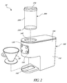
- FIG 1 illustrates a system 10 for grinding a material.
- the system 10 comprises a grinding apparatus or grinding machine 100 and an apparatus for containing a material or a container 200.
- the illustrated embodiment also shows a material holder 20 for receiving ground material.
- the material holder 20 may comprise a filter holder, which is illustrated in Figure 1 , to be used with pour-over beverage brewing machines or any other suitable holder for containing the ground material to be used with any type of beverage brewing apparatus or machine.
- the container 200 is configured to engage with the grinding apparatus 100 to provide a dose of coffee beans to the grinding apparatus 100.
- the grinding apparatus 100 may comprise standard components of a grinding machine such as a motor and a grind head. Many conventional grinding apparatus also include a directing component, such as an auger, to direct coffee beans toward grinding components of the grinding machine. In some embodiments of the disclosed system 10, the grinding apparatus 100 does not include a directing component to direct the material toward grinding features. Instead, the container 200 comprises a directing component to direct or guide the material toward an opening in the container. In such embodiments, the system 10 may be easier to use than conventional grinding systems because, for example, a user may not need to clean the grinder apparatus 100 between uses since controlled doses of coffee beans may be provided to the grinding apparatus 100, thereby minimizing leftover coffee beans and residue in the grinding apparatus 100.
- a directing component such as an auger
- both the grinding apparatus 100 and the container 200 may include directing components to direct coffee beans.
- the grinding apparatus 100 may include a control panel with various control buttons corresponding to different sizes of coffee cups. A barista may select a particular control button to convey information about the desired coffee size and to initiate the grinding process.
- the container 200 may have characteristics of any suitable container or canister used to store coffee beans.
- the container 200 is substantially airtight when in a closed configuration to preserve the life and freshness of coffee beans stored therein.
- the container 200 may be configured to store a variety of different types of coffee beans, which may have different sizes, shapes, and densities.
- the system 10 may employ many different containers 200 such that a user may exchange one container for another to use with the grinding apparatus 100.
- the modular nature of the containers, as well as other features allows a user to efficiently and easily grind a variety of different types of coffee beans with minimal maintenance of the grinding apparatus 100.
- the container 200 may also serve to function as a hopper for the system 10.
- the container 200 can contain and deliver coffee beans to a grinding element of the system 10 to grind the coffee beans.
- FIG 2 shows the system of Figure 1 in an exploded configuration.
- the apparatus for containing a material 200 may be removed from the grinding apparatus 100.
- the grinding apparatus 100 comprises a rear portion 110 and a front portion 120.
- the front portion 120 may comprise an engagement portion 130 configured to engage with the container 200.
- the engagement portion 130 defines an opening 140 configured to receive at least a portion of the container 200.
- the grinding apparatus 100 may also comprise a cover 104 that may be removably attached to the grinding apparatus 100. The cover 104 may be removed to access internal components of the grinding apparatus 100.
- the container 200 may comprise a body portion 220 and a base portion 230.
- the base portion 230 is configured to engage with the body portion 220 such that the base portion 230 is integral with the body portion 220 of the container 200.
- the base portion 230 may be configured to be removably attached to the body portion of the container 220 such that the base portion 230 and the body portion 220 comprise separate components when detached from each other.
- the container 200 may include a cap 210 to close and seal the container 200.
- the container 200 may include identification information about the coffee beans contained therein. Such identification information may be transmitted to the grinding apparatus 100 so that the grinding apparatus 100 can determine how long to grind a particular type of coffee.
- the system 10 may also transmit such identification information, as well as the size of coffee portion desired by a customer, to a beverage brewing apparatus so that the beverage brewing apparatus can determine how long to brew the coffee.
- the container 200 and/or the grinding apparatus 100 may include an optical identification component to receive, store, and transmit such identification information.
- the material holder 20 may also be removed from the grinding apparatus 100.
- the grinding apparatus 100 may include a support member 102 for supporting the material holder 20 when the system 10 is being used to grind a material. After coffee beans are ground and received in the material holder 20, the material holder 20 may be removed from the support member 102 of the grinding apparatus 100 and provided to a beverage brewing apparatus to brew the coffee.
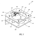
- FIG. 3 shows a rear perspective view of the engagement portion 130 of the grinding apparatus 100.
- the grinding apparatus may comprise a rear portion 110 and a front portion 120.
- the front portion 120 comprises an engagement portion 130 configured to receive a container of coffee beans.
- the engagement portion 130 comprises a first surface 132 and a second surface 134.
- the second surface 134 is attached to the first surface 132 by one or more support members 136 such that second surface 134 is disposed above the first surface 132.
- the second surface 134 may have other orientations with respect to the first surface 132, such as to the side of, in front of, behind, or below the first surface 132.
- the second surface 134 may define an opening 140 to receive at least a portion of a container.
- the opening 140 is substantially circular in configuration.
- the opening 140 may define other configurations to receive a suitable container, including, but not limited to, substantially rectangular, triangular, ovoid, or elliptical.
- the opening 140 may include a recessed portion 142 configured receive a protruding portion of the container 200, such as an actuator housing.
- An actuator housing 234 of the container 200 is shown in Figure 7 .
- the first surface 132 of the engagement portion 130 may define an opening 150 to allow coffee beans to pass therethrough.
- a funnel 170 (which is depicted in Figures 5 and 6 ) may be attached to the opening 150 to funnel coffee grounds to grinding features of the grinding apparatus 100 to grind the coffee beans.
- the first surface 132 may also include a door opening mechanism 152 and a securing component 154.
- the securing component 154 may interact with a container to attach and secure the container to the grinding apparatus 100 during operation. The securing component 154 may reduce the risk that a container is removed from the grinding apparatus 100 during operation.
- the securing component 154 may also be configured to detect a container and have a safety feature where the grinding apparatus 100 does not turn on unless the securing component 154 detects that at least a portion of the container is positioned at a suitable location with respect to the engagement portion 130.
- the securing component 154 may also detect when a container is removed from the engagement portion 130 and deactivate the grinding apparatus 100 when the container is removed.
- the securing component 154 comprises a magnet. In other embodiments, the securing component comprises an element configured to engage with a magnet disposed on a base portion of the container.
- the securing component 154 may also comprise a solenoid interlock that engages with the container, or an element that interacts with a solenoid interlock on the container.
- the securing component 154 may release when the grinding process is complete to allow a user to remove a container from the grinding apparatus 100.
- the securing component 154 may also comprise a Hall effect sensor to detect and secure a container of coffee beans.
- the securing component 154 may also comprise an optical sensor.
- the securing component 154 may comprise one or more mechanical interlocks, including, but not limited to, an undercut or a lock that engages with a portion of the container.
- the door opening mechanism 152 is configured to engage with the container 200 to open and close a door 260 (which is depicted in Figures 9 and 10A-10C ) on the container 200 to release ground material from the container 200.
- the door opening mechanism 152 comprises a movable pin.
- the pin 152 may move up and down with respect to first surface 132 of the engagement portion 130.
- a leading end of the pin 152 may be substantially flush with the first surface 132 such that the pin 152 is disengaged from a container when the container is connected to the engagement portion 130.
- a leading end of the pin 152 may project outward from the first surface 132 to engage the container to open a door 260 on the container 200.
- Movement of the pin 152 may be automatically controlled by the grinding apparatus 100 and dependent upon the type of coffee beans to be ground and/or the size of coffee portion desired by a user.
- the pin 152 may be actuated in a variety of ways, including, but not limited to, automatic actuation by using a solenoid.
- the pin 152 may comprise a rigid component that does not move with respect to the first surface 132.
- the pin 152 may engage the container 200 to open a door 260 (which is depicted in Figures 9 and 10A-10C ) the container and to keep the door 260 open when the container 200 is engaged with the engagement portion 130 of the grinding apparatus 100.
- a directing component 244 such as an auger, controls and limits the amount of coffee beans dispensed through the opening and into the grinding apparatus 100.
- Figures 7-9 illustrated embodiments of the container 200, directing component 244, and door 260.
- Other suitable door opening mechanisms 152 may be used, such as a variety of passive actuators, passive pushers, pivot pieces, and solenoids.
- a solenoid actuates the pin 152 and locks the pin 152 into the container 200 to ensure that the container 200 may not be removed from the grinding apparatus 100 during operation.
- securing the container 200 to the grinding apparatus 100 by use of a solenoid-actuated pin may be used instead of the securing component 154.
- the system 10 may comprise both a solenoid-actuated pin and a securing component 154.
- the engagement portion 130 may include an actuator portion 160.
- the actuator portion 160 is configured to engage with an actuator of a container to actuate a directing component of the container to guide a desired amount of coffee beans toward an opening in the container.
- the actuator portion 160 of the engagement portion 130 may comprise a first gear 164 and a second gear 162.
- the first gear 164 is in communication with a motor of the grinding apparatus 100.
- the second gear 162 is configured to mate with the first gear 164.
- the motor may activate the first gear 164.
- the first gear 164 then will cause the second gear 162 to rotate with respect to a central pivot point.
- Figure 4 shows a side view of the engagement portion 130 of the grinding apparatus 100.
- the door opening mechanism 152 protrudes and extends upwardly from the first surface 132.
- a distance between the first surface 132 and the second surface 134 may be similar to a height of a portion of the container 200 configured to engage with the grinding apparatus 100.
- Figure 5 illustrates a top view of the engagement portion 130.
- a perimeter edge associated with the opening 150 may couple to a funnel 170 to collect and funnel coffee beans to grinding components of the grinding apparatus 100.
- the door opening mechanism 152 is shown near a lower right portion of the opening 150 in Figure 5 . However, the door opening mechanism 152 may be positioned at other locations on the first surface 132.
- the engagement portion 130 may comprise more than one door opening mechanism 152.
- a second door opening mechanism may be disposed on an opposite side of the opening 150 and be configured to engage with a base portion 230 of a container 200.
- Figure 6 shows an embodiment of the grinding apparatus 100 having an anti-static tongue to facilitate collection and release of excess ground coffee from the grinding apparatus 100.
- Static tends to cause coffee grinds to cling to internal components of grinding machines instead of being delivered to a material holder or coffee filter.
- the disclosed embodiment of a movable anti-static tongue is designed to address this issue.
- the front portion 120 of the grinding apparatus 100 may comprise a funnel 170.
- the funnel 170 is attached, either directly or indirectly, to the engagement portion 130 of the grinding apparatus 100.
- the funnel 170 is connected to a chute 124 at a lower end thereof.
- a portion of a grind head 112 of the grinding apparatus 100 is shown in Figure 6 between the funnel 170 and the chute 124.
- the grind head 112 may comprise conventional grinding components configured to grind coffee beans.
- a tongue feature 113 may engage with the chute 124.
- the tongue feature 113 comprises a support member 115 that defines a slot 116, an actuator 117, and a rod 118 attached to a tongue 114.
- the rod 118 may be configured to fit within the slot 116.
- the tongue 114 may be configured within a portion of the chute 124 to direct coffee grounds to collect in a relatively compact space and to flow more uniformly through the chute 124.
- the actuator 117 may actuate the rod 118 so that the rod 118 moves linearly within the slot 116.
- the actuator 117 comprises a solenoid.
- the tongue 114 may also translate to facilitate substantially uniform flow of grounds through the chute 124 and opening 126.
- the rod 118 and tongue 114 may move back-and-forth with respect to the slot 118 and opening 126, respectively.
- the actuator 117 is configured to move the tongue 114 along a linear path. In other embodiments, however, the actuator 117 may move the tongue along other path configurations, such as a rotational path.
- the actuator 117 may comprise a solenoid.
- the tongue 114 may be flexible and bend downward upon accumulating coffee grounds.
- the tongue 114 may act as a spring, serve as a gate valve, and/or serve as a plate that is cantilevered from one side.
- the tongue 114 may be pulled away from the opening 126 after the grinding apparatus 100 is turned off.
- the tongue 114 may be pulled away, however, while grinding components are still rotating or moving so that movement of the tongue 114 dislodges or knocks down excess grinds caught on an interior portion of the grinding apparatus 100.
- the tongue 114 may also be actuated with an impact force such that the force further dislodges or removes excess grinds.
- the tongue 114 may contact a hard stop after being actuated with such an impact force.
- the tongue 114 may be pulled away from the grinding apparatus 100 after the grinding apparatus 100 is turned off and after grinding components have stopped rotating or otherwise moving.
- the tongue 114 may be pulled away from the grinding apparatus 100 while the grinding apparatus 100 is still turned on.
- the container 200 may include a body portion 220 and a base portion 230 attached to the body portion 220.
- the body portion 220 has a first end portion 222, a second opposing end portion 224, and a central portion 226 disposed between the end portions 222, 224.
- the first end portion 222 defines an opening 228 in the container 200.
- the opening 228 allows a user to add coffee beans to or remove beans from the container 200.
- the opening 228 allows a user to access internal components of the container 200 to maintain and clean those components.
- the container 200 may include a cap 210 configured to engage with the first end portion 222 of the body portion 220 to substantially seal the container 200 from the surrounding environment.
- the base portion 230 may be integrally attached to the second end portion 224 of the body portion 220.
- the illustrated embodiment shows a substantially cylindrical container 200; however, the container 200 may comprise a variety of configurations, shapes, and sizes.
- the base portion 230 of the container 200 may be configured to engage with the engagement portion 130 of the grinding apparatus 100.
- the base portion 230 of the illustrated embodiment has an outer surface 232 that fits through the opening 140 of the engagement portion 130 of the grinding apparatus 100.
- the outer surface 232 of the base portion 230 may have an actuator housing 234 configured to receive an actuator 236.
- the actuator 236 comprises a gear.
- the actuator 236 may comprise a friction wheel, a toothed belt, and/or a timing belt.
- the base portion 230 may include a solenoid and/or magnet configured to engage with a securing component 154 of a grinding apparatus 100 to securely attached the base portion 230 to an engagement portion 130 of the grinding apparatus 100.
- a magnet may allow a grinding apparatus 100 to sense that the base portion 230 is engaged with the grinding apparatus 100.
- the grinding apparatus 100 may not activate until it senses the magnet of the base portion 230, thereby improving safety to users when operating the system 100.
- the base portion 230 may also have a support member 240 to help support and contain coffee beans disposed within the container 200.
- the support member defines a channel 242 that is configured to receive and provide a recess for a directing component 244.
- the directing component 244 may be directly or indirectly connected to the actuator 236 of the base portion 230. When activated by the actuator 236, the directing component 244 may rotate about a central axis to guide coffee beans toward an opening 254 in a bottom surface 252 of the base portion 230.
- the opening 254 is shown in Figure 9 .
- the directing component 244 comprises an auger.
- the directing component 244 comprises a conveyor belt and/or a paddle wheel.
- the system 10 may be configured to control the pitch of the auger so that the auger stops at substantially the same position each time the grinding process has finished. Doing so may improve the consistency of the amount of coffee beans released from the container 100. When the auger stops at different orientations, there may be some variance in the dose of coffee beans released because certain orientations may trap more or less beans than other orientations.
- an encoder may be used to detect the pitch of the auger and facilitate positioning the auger in substantially the same position after each use.
- the base portion 230 may also include a plate 246. As illustrated in Figure 8 , the plate 246 may be disposed over a portion of the support member 240 near a tip of the directing component 244 and over an opening in a bottom surface of the base portion 230. The plate 246 may assist in delivering ground coffee through the opening in the bottom surface by providing a barrier so that coffee grounds are directed toward the opening. The plate 246 may also provide safety functions by providing a barrier between a tip of the directing component 244 and an open space in the container where a user may place his or her hand. In some embodiments, the plate 246 may substantially cover the support member 240 to block inadvertent access to the directing component 244 while the directing component 244 is activated and directing coffee beans.
- the bottom end portion 250 may comprise a bottom surface 252 and a door 260.
- the bottom surface 252 defines an opening 254 configured to allow coffee grounds to pass therethrough.
- the door 260 substantially covers the opening 254 in the bottom surface 252.
- the door 260 may include a protrusion 262 configured to cover the opening 254 and a plate 264 attached to the protrusion 262 and extending across a portion of the bottom surface 252.
- the plate may have a first arm 266 and a second arm 268.
- the first arm 266 and second arm 268 may be attached to a first ramped component 270 and a second ramped component 272, respectively.
- the bottom surface 252 defines a first track 280 and a second track 282, which are configured to receive the ramped components 270, 272.
- the track may also contain a first spring 290 and a second spring 292.
- the springs 290, 292 are illustrated in Figures 10A-10C . In the illustrated embodiments, the springs 290, 292 are disposed on a side of the end portion 250 near the actuator housing 234.
- the bottom end portion 250 may also include an engagement plate 212 attached to the bottom surface 252.
- the engagement plate 212 overlies portions of the door 260 to protect and cover the door 260, yet allow the door 260 to move with respect to the bottom surface 252 and engagement plate 212.
- the engagement plate 212 defines a first slot 214 and a second slot 216.
- the first slot 214 comprises an opening that may be substantially similar in shape to the first track 280 of the bottom surface 252.
- the second slot 216 comprises an opening that may be substantially similar in shape to the second track 282.
- the slots 214, 216 provide openings to access the tracks 280, 282 and components contained therein, such as arms 266, 268, ramped surfaces 270, 272, and springs 290, 292.
- the slots 214, 216 also allow the arms 266, 268 and ramped surfaces 270, 272 to move with respect to the bottom surface 252.
- the engagement plate 212 is configured to engage with an engagement portion 130 of a grinding apparatus 100.
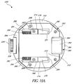
- Figures 10A-10C illustrate embodiments of the door 260 shown in different configurations with respect to the opening 254 of the base portion 230.
- Figure 10A shows an embodiment where the door 254 is in a closed configuration;
- Figure 10B shows the door in a partially-open configuration;
- Figure 10C shows the door in a fully-open configuration.
- Figures 9 and 10A-10C show embodiments of the base portion 230 having two tracks, slots, arms, ramped surfaces, and springs
- other embodiments of the base portion 230 may include only a single track, slot, arm, ramped surface, and spring.
- other embodiments of the base portion 230 may include more than two tracks, slots, arms, ramped surfaces, and springs.
- the base portion 230 may include some but not all of the track, slot, arm, ramped surface, and spring. Other embodiments of the base portion 230 may include structure to linearly translate the door 260 without using a ramped surface. For example, in some embodiments the door 260 may be actuated by a transducer, such as a solenoid. Further, other embodiments of the base portion 230 may comprise other configurations to move the door 260 apart from, or in addition to, linear translation, such as configurations providing structure to allow the door 260 to rotate with respect to the opening 254. Accordingly, it should be understood that many variations and modifications of the door 260 and structure to move the door 260 may be made to the embodiments disclosed herein.
- the door 260 is shown in a closed position.
- the protrusion 262 of the door 260 extends over the opening 254 in the bottom surface 252 such that the protrusion 262 substantially covers the opening 254. In some embodiments, the protrusion 262 may not entirely cover the opening 254 when the door is in a closed position.
- the first ramped component 270 comprises a first leading edge 271 and the second ramped component 272 comprises a second leading edge 273.
- the first leading edge 271 is disposed near a first proximal end 281 of the first track 280
- the second leading edge 273 is disposed near a second proximal end 283 of the second track 282.
- the first spring 290 and the second spring 292 each are in a rested position. In such a position, the springs 290, 292 engage with the arms 266, 268 and the ramped components 270, 272 to bias the door 260 in a closed position with respect to the opening 254.
- the door 260 has been translated linearly toward a trailing portion 294 of the bottom surface 252.
- the trailing portion 294 is disposed on a portion of the bottom surface 252 away from the opening 254.
- the trailing portion 294 is disposed near the actuator housing 234.
- the leading edges 271, 273 of the ramped components 270, 272 are translated away from proximal ends 281, 283 of the tracks 280, 282.
- the translation may occur by engaging one or more door opening mechanisms 152 with one or more of the ramped components 270, 272.
- the first arm 266 comprises a first trailing edge 267 and the second arm 268 comprises a second trailing edge 269.
- first track 280 may comprise a first distal end 291 and the second track 282 may comprise a second distal end 293.
- the trailing edges 267, 269 of the arms 266, 268 may translate linearly toward the distal ends 291, 293 of the tracks 280, 282, respectively.
- the springs 290, 292 may compress to accommodate such linear translation of the door 260.
- Figure 10C shows the door 260 in an open position.
- the springs 290, 292 may be fully compressed such that trailing edges 267, 269 of the arms 266, 268 are disposed near distal ends 291, 293 of the tracks 280, 282, respectively.
- the leading edges 271, 273 of the ramped components 270, 272 have been further translated toward the trailing portion 294 of the bottom surface 252 such that a greater portion of each track 280, 282 is now visible from a bottom view.
- the opening preferably allows a controlled dose of coffee beans to exit the base portion 230 of the container 200.
- the door 260 may close by releasing a door opening mechanism 152 from engagement with the door 260.
- the springs 290, 292 may release stored potential energy to exert a force on the arms 266, 268 to linearly translate the door 260 away from the trailing portion 294 toward a leading portion 295 of the bottom surface 252 to close the opening 254.
- the apparatus of the system 10 may comprise more than one door.
- the container 200 may comprise a first door and the grinding apparatus 100 may comprise a second door.
- the first door of the container 200 may function similar to the door 260, as described above.
- the first door of the container 200 may open and close to release a desired amount of coffee beans to a grinding apparatus 100.
- the second door of the grinding apparatus 100 may function to prevent access to internal components of the grinding apparatus 100 so as to facilitate enhanced safety characteristics of the system 10.
- the second door of the grinding apparatus 100 may prevent a user from accessing internal components of the grinding apparatus 100 when the grinding apparatus is not in use.
- the second door may prevent debris from entering the grinding apparatus 100, thereby facilitating enhanced health and sanitary conditions of systems for grinding and brewing coffee.
- the first door and second door may each be individually actuated by a transducer, such as a solenoid.
- the solenoid may engage pins that actuate the first door and second door.
- the first door and second door may also be actuated by pins similar to the way in which the pin 152 actuates the door 260 of the container 200, as illustrated and described above with respect to Figures 7-10 .
- the first door and second door may be actuated through a combination of rigid or movable pins and transducers.
- Figure 11 illustrates embodiments of a container 400 where a body portion 420 and a base portion 430 of the container 400 comprise separate components.
- the body portion 420 may be substantially similar in structure to embodiments of the body portion 220 of the container 200 described above with reference to Figures 1-10 .
- the base portion 430 is substantially similar in structure to embodiments of the base portion 230 described above with reference to Figures 1-10 .
- the body portion 420 may include a first mating portion 402 and the base portion 430 may have a corresponding second mating portion 404.
- the first mating portion 402 may be configured to engage with the second mating portion 404 to attach the body portion 420 to the base portion 430 of the container 400.
- the first mating portion 402 may also be configured to disengage from the second mating portion 404 to detach the body portion 420 from the base portion 430.
- the base portion 430 may be configured to removably attach to the body portion 420 such that the base portion 430 and body portion 440 comprise separate components when detached from each other.
- the mating portions 402, 404 comprise threaded components.
- the body portion 420 may be attached to the base portion 430 by mating the threaded components and rotating the body portion 420 about a longitudinal axis with respect to the base portion 430.
- Other structure may be used to removably attach the body portion 420 to the base portion 430.
- such a connection may be made by structure such as corresponding pin and slots, corresponding tabs and recesses, and/or adhesives.
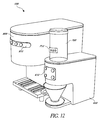
- Figure 12 shows embodiments of a system 500 for grinding a material where the system 500 includes a beverage brewing apparatus.
- the system 500 may include a grinding apparatus 600, an apparatus for containing a material or a container 700, and a beverage brewing apparatus 800.
- the grinding apparatus 600 and the container 700 may be similar to embodiments of the grinding apparatus 100 and the container 200, 400 described above.
- the beverage brewing apparatus 800 may be configured to receive coffee grounds from the grinding apparatus 600 and/or the container 700 to brew one or more cups of coffee.
- the grinding apparatus 600 may include a control panel 610
- the container 700 may include a control panel 710
- the beverage brewing apparatus 800 may include a control panel 810 so that any or all of the grinding apparatus 600, container 700, and beverage brewing apparatus 800 can communicate with one another.
- the grinding apparatus 600, container 700, and beverage brewing apparatus 800 may communicate information such as coffee bean type, bean density, bean size, and size of the desired coffee portion (e.g., small, medium, large, extra large, tall, grande, venti, trenti, etc.). Other information may also be communicated so that the grinding and brewing process may be employed easily and efficiently. Communication across multiple platforms may be employed through a variety of ways, including, but not limited to, wireless, Ethernet, serial, and ZigBee.
- the beverage brewing apparatus 800 comprises the Clover® Brewing System, which is currently available at certain Starbucks® stores.
- Embodiments of the Clover® Brewing System are illustrated and described in U.S. Patent No. 7,673,555, which issued on March 9, 2010 and is titled "Machine for Brewing a Beverage Such as Coffee and Related Method," the entire content of which is hereby incorporated by reference in its entirety.
- the container and grinding apparatus may be used at a commercial setting, such as a coffee shop.
- the coffee shop may have several containers, such as five or more, each of which stores a different type of coffee bean.
- a customer may order a medium-sized cup of a particular type of coffee.
- a barista may select the appropriate container of coffee beans and proceed to place the container within the engagement portion of the grinding apparatus.
- the grinding apparatus may have a control panel where the barista selects a control corresponding to a medium-sized cup of coffee.
- the grinding apparatus recognizes the type of coffee beans in the container and is programmed to active a motor to drive an actuator for an appropriate specified period of time corresponding to the type of coffee bean and desired size of coffee cup.
- the motor may recognize the type of coffee bean and desired portion of coffee, and then activate at a preferable speed and for an appropriate time to grind the coffee.
- the actuator of the grinding apparatus is actuated and engages with an actuator on the base portion of the container.
- the actuator on the base portion of the container then drives a directing component, such as an auger, to direct the coffee beans toward an opening in the base portion.
- a door opening mechanism of the engagement portion of the grinding apparatus engages with the door of the container.
- the door then may open to release a desired quantity of coffee beans through openings in the container and engagement portion.
- the grinding apparatus then grinds the coffee beans and delivers the grounds to a material holder, such as a coffee filter holder.
- a securing mechanism on the engagement portion of the grinding apparatus may interact with the base portion of the container to securely attach the container to the grinding apparatus when the grinding apparatus is turned on.
- the motor of the grinding apparatus deactivates to stop the actuators, the directing components, and grinding features of the grinding apparatus.
- the door opening mechanism also disengages from the door to close the door with respect to the opening in the bottom surface of the base portion of the container.
- a barista may transfer the ground coffee to a beverage brewing apparatus to brew a cup of coffee.
- the barista may also remove the container from the grinding apparatus. If a customer then orders a different type of coffee, the barista may repeat this process by using a different container holding the different type of coffee beans.
- the barista need not spend time and effort cleaning the grinding apparatus between uses or weighing a particular amount of coffee beans to be used for single-cup brewing.
- a removable container has a built-in directing component and a grinding apparatus has grinding features to grind coffee beans.
- the grinding apparatus may have built-in grinding features instead of, or in addition to, the grinding apparatus and the container may have a door to provide a controlled dose of ground coffee to the grinding apparatus or directly to a material holder.
- the grinding apparatus may have directing components instead of, or in addition to, the container.
- the grinding apparatus may include one or more augers.
Landscapes
- Engineering & Computer Science (AREA)
- Food Science & Technology (AREA)
- Mechanical Engineering (AREA)
- Apparatus For Making Beverages (AREA)
Applications Claiming Priority (2)
| Application Number | Priority Date | Filing Date | Title |
|---|---|---|---|
| US13/251,157 US8944354B2 (en) | 2011-09-30 | 2011-09-30 | Apparatus, systems, and methods for grinding a material |
| PCT/US2012/054515 WO2013048707A1 (en) | 2011-09-30 | 2012-09-10 | Apparatus, systems, and methods for grinding a material |
Publications (2)
| Publication Number | Publication Date |
|---|---|
| EP2760320A1 EP2760320A1 (en) | 2014-08-06 |
| EP2760320B1 true EP2760320B1 (en) | 2016-07-13 |
Family
ID=46968363
Family Applications (1)
| Application Number | Title | Priority Date | Filing Date |
|---|---|---|---|
| EP12767151.9A Active EP2760320B1 (en) | 2011-09-30 | 2012-09-10 | Apparatus, systems, and methods for grinding a material |
Country Status (8)
| Country | Link |
|---|---|
| US (2) | US8944354B2 (ja) |
| EP (1) | EP2760320B1 (ja) |
| JP (1) | JP6223344B2 (ja) |
| CN (1) | CN104159480B (ja) |
| CA (1) | CA2848305C (ja) |
| ES (1) | ES2586400T3 (ja) |
| HK (1) | HK1200678A1 (ja) |
| WO (1) | WO2013048707A1 (ja) |
Cited By (1)
| Publication number | Priority date | Publication date | Assignee | Title |
|---|---|---|---|---|
| DE202017001402U1 (de) * | 2017-03-15 | 2018-06-18 | Bean Industries Limited | Kaffeefiltermaschine und System, welches die Kaffeefiltermaschine umfasst |
Families Citing this family (26)
| Publication number | Priority date | Publication date | Assignee | Title |
|---|---|---|---|---|
| US8944354B2 (en) | 2011-09-30 | 2015-02-03 | Starbucks Corporation | Apparatus, systems, and methods for grinding a material |
| US9033269B2 (en) * | 2013-03-01 | 2015-05-19 | Whirlpool Corporation | Linear path food processor |
| US9930989B2 (en) | 2013-03-14 | 2018-04-03 | Spectrum Brands, Inc. | Apparatus for brewing beverages |
| EP2991528B1 (en) * | 2013-04-02 | 2017-08-09 | Koninklijke Philips N.V. | Beverage-producing machine comprising a removable ingredient container |
| CA2858015C (en) * | 2013-08-01 | 2021-01-19 | Roger Lawson | Automated hot beverage brewing machine |
| ITMI20131423A1 (it) * | 2013-08-29 | 2015-03-01 | Marzocco Srl | Macchina macina caffe' |
| TWM521433U (zh) * | 2016-02-17 | 2016-05-11 | Chouki Internat Company Ltd | 沖泡材料磨碎機 |
| CN107307759B (zh) * | 2016-04-27 | 2020-07-21 | 漳州灿坤实业有限公司 | 磨豆机 |
| CN206183046U (zh) * | 2016-08-23 | 2017-05-24 | 广东新宝电器股份有限公司 | 磨粉组件及咖啡机 |
| US10226147B2 (en) | 2017-01-06 | 2019-03-12 | David Harper | Beverage brewing device |
| US10912418B2 (en) | 2017-10-05 | 2021-02-09 | Helen Of Troy Limited | Coffee grinder with static electricity ground |
| CN117322765A (zh) | 2017-12-22 | 2024-01-02 | 科瑞特里克斯股份公司 | 用于定量配给咖啡豆的设备 |
| TWI653957B (zh) | 2018-03-07 | 2019-03-21 | 吉諾工業有限公司 | 送料機構及送料機構與研磨機的組合 |
| CN110236416A (zh) * | 2018-03-07 | 2019-09-17 | 吉诺工业有限公司 | 送料机构及送料机构与研磨机的组合 |
| JP7240113B2 (ja) * | 2018-08-29 | 2023-03-15 | 株式会社ツインバード | コーヒーメーカー |
| EP3662794A1 (en) * | 2018-12-04 | 2020-06-10 | Hemro International AG | Method for controlling a coffee grinder |
| CN109381023A (zh) * | 2018-12-10 | 2019-02-26 | 金文� | 一种研磨咖啡机 |
| KR200493831Y1 (ko) * | 2019-01-24 | 2021-06-10 | 김정규 | 드립퍼 장착이 가능한 핸드밀 |
| WO2020252491A2 (en) * | 2019-06-13 | 2020-12-17 | Ricconics Llc | Coffee system and method |
| US11871866B2 (en) | 2020-06-02 | 2024-01-16 | Starbucks Corporation | Modular brew systems |
| DE102021102743B3 (de) | 2021-02-05 | 2022-07-07 | Next Level Coffee GmbH | Automatisiert einstellbare Kaffeemaschine und zugehöriger Kaffeebohnenbehälter |
| JP7158066B2 (ja) * | 2021-03-19 | 2022-10-21 | 株式会社大都技研 | コーヒーマシン |
| US11370604B1 (en) * | 2021-03-25 | 2022-06-28 | Gil Gold | Dispensing system |
| EP4370443A1 (en) * | 2021-07-15 | 2024-05-22 | Terra Kaffe | Improved automated method and system for processing a desired dose of particles from a particle storage container |
| IT202100024248A1 (it) * | 2021-09-21 | 2023-03-21 | De Longhi Appliances Srl | Macchina e procedimento per la preparazione di bevande a base di chicchi di caffè |
| JP7361237B1 (ja) * | 2023-06-05 | 2023-10-13 | 小泉成器株式会社 | コーヒーグラインダースタンド |
Family Cites Families (16)
| Publication number | Priority date | Publication date | Assignee | Title |
|---|---|---|---|---|
| JPS5849718Y2 (ja) * | 1979-04-24 | 1983-11-12 | 松下電器産業株式会社 | コ−ヒ−豆粉砕器付きコ−ヒ−沸し器 |
| JPS6023892B2 (ja) | 1979-05-22 | 1985-06-10 | 日本鋼管株式会社 | 厚肉鋼管製造方法 |
| DE3733487C2 (de) | 1987-10-03 | 1997-08-14 | Leybold Ag | Vorrichtung zum Ziehen von Einkristallen |
| JPH0196087U (ja) * | 1987-12-17 | 1989-06-26 | ||
| US4913037A (en) | 1989-06-06 | 1990-04-03 | Grindmaster Corporation | Moisture protection system for the particulate food delivery apparatus of beverage preparing means |
| US5241898B1 (en) * | 1992-09-25 | 1999-02-09 | Grindmaster Corp | Coffee dispenser and brewer apparatus |
| EP0605750B1 (de) | 1993-01-08 | 1997-04-02 | Wmf Württembergische Metallwarenfabrik Ag | Kaffeemaschine |
| DE102004024713A1 (de) * | 2004-05-19 | 2005-12-15 | Melitta Haushaltsprodukte Gmbh & Co. Kg | Mahlvorrichtung für Kaffeebohnen |
| CN2764276Y (zh) * | 2005-01-19 | 2006-03-15 | 许德晞 | 一种改进型的手工磨咖啡豆机 |
| RU2387360C2 (ru) | 2005-04-11 | 2010-04-27 | Старбакс Корпорейшн | Машина и способ для приготовления напитка, такого как кофе |
| WO2009047590A1 (en) | 2007-10-12 | 2009-04-16 | Bich Francois | Grinding system, grinding mill for such grinding system and reload cartridge for such grinding system. |
| SI2071986T1 (sl) | 2007-12-18 | 2012-04-30 | Nestec Sa | Sistem za pripravo napitka iz sestavin, podprt s kodiranim vloĹľkom |
| RU2538539C2 (ru) | 2008-09-17 | 2015-01-10 | Конинклейке Дауве Эгбертс Б.В. | Система для приготовления кофейного напитка |
| MX370728B (es) | 2009-02-17 | 2019-12-20 | Douwe Egberts Bv | Cartucho de empacado de grano de cafe y sistema de bebida de cafe que incluye el mismo. |
| FR2956303B3 (fr) * | 2010-02-17 | 2012-10-05 | Sara Lee / De N V | Systeme de preparation pour boisson au cafe, cartouche de conditionnement de cafe moulu pour une utilisation avec un tel systeme, procede de preparation d'une boisson au moyen dudit systeme, et procede de fourniture de cafe moulu a partir de ladite cartouche de conditionnement de cafe moulu |
| US8944354B2 (en) | 2011-09-30 | 2015-02-03 | Starbucks Corporation | Apparatus, systems, and methods for grinding a material |
-
2011
- 2011-09-30 US US13/251,157 patent/US8944354B2/en active Active
-
2012
- 2012-09-10 CA CA2848305A patent/CA2848305C/en active Active
- 2012-09-10 CN CN201280047519.4A patent/CN104159480B/zh active Active
- 2012-09-10 EP EP12767151.9A patent/EP2760320B1/en active Active
- 2012-09-10 JP JP2014533558A patent/JP6223344B2/ja active Active
- 2012-09-10 ES ES12767151.9T patent/ES2586400T3/es active Active
- 2012-09-10 WO PCT/US2012/054515 patent/WO2013048707A1/en active Application Filing
-
2015
- 2015-02-02 US US14/611,973 patent/US10368694B2/en active Active
- 2015-02-06 HK HK15101389.0A patent/HK1200678A1/xx unknown
Cited By (1)
| Publication number | Priority date | Publication date | Assignee | Title |
|---|---|---|---|---|
| DE202017001402U1 (de) * | 2017-03-15 | 2018-06-18 | Bean Industries Limited | Kaffeefiltermaschine und System, welches die Kaffeefiltermaschine umfasst |
Also Published As
| Publication number | Publication date |
|---|---|
| CN104159480A (zh) | 2014-11-19 |
| JP2014530684A (ja) | 2014-11-20 |
| US20130082130A1 (en) | 2013-04-04 |
| WO2013048707A1 (en) | 2013-04-04 |
| CN104159480B (zh) | 2017-03-01 |
| CA2848305A1 (en) | 2013-04-04 |
| US10368694B2 (en) | 2019-08-06 |
| CA2848305C (en) | 2018-07-10 |
| EP2760320A1 (en) | 2014-08-06 |
| US8944354B2 (en) | 2015-02-03 |
| US20150144720A1 (en) | 2015-05-28 |
| JP6223344B2 (ja) | 2017-11-01 |
| HK1200678A1 (en) | 2015-08-14 |
| ES2586400T3 (es) | 2016-10-14 |
Similar Documents
| Publication | Publication Date | Title |
|---|---|---|
| EP2760320B1 (en) | Apparatus, systems, and methods for grinding a material | |
| AU2017323398B2 (en) | Beverage machine with ergonomic handling | |
| RU2561027C2 (ru) | Система приготовления кофейного напитка, картридж упаковки кофейных зерен для использования с упомянутой системой, способ приготовления напитка, способ варки кофе, картридж для материала кофейных зерен, способ подачи материала кофейных зерен | |
| NL2006237C2 (en) | Coffee beverage system, coffee bean packaging cartrige for use with said system, method of preparing a beverage, method for brewing coffee, method of supplying coffee beans, cartridge for coffee bean material, method of supplying coffee bean material. | |
| JP2013519490A5 (ja) | ||
| US7975882B2 (en) | Dispenser of powdered product having a removable reservoir | |
| JP6038140B2 (ja) | 粉末容器のシュートを自動的に閉鎖する飲料ディスペンサ | |
| JP2013519487A5 (ja) | ||
| EP2358245A2 (en) | System, package, apparatus and method for dosing coffee beans | |
| MX2013007397A (es) | Aparato y metodo para bebida preparada. | |
| US10945552B2 (en) | Beverage machine with an ergonomic water storage | |
| WO2016083484A1 (en) | Ergonomic handle arrangement | |
| RU2596961C2 (ru) | Устройство для отделения друг от друга двух областей | |
| CN109219377B (zh) | 配备有咖啡粉输送装置的咖啡机 | |
| US11344149B2 (en) | Beverage machine with ergonomic power switch | |
| JP7382398B2 (ja) | 飲料マシンの適応サービスユニット |
Legal Events
| Date | Code | Title | Description |
|---|---|---|---|
| PUAI | Public reference made under article 153(3) epc to a published international application that has entered the european phase |
Free format text: ORIGINAL CODE: 0009012 |
|
| 17P | Request for examination filed |
Effective date: 20140415 |
|
| AK | Designated contracting states |
Kind code of ref document: A1 Designated state(s): AL AT BE BG CH CY CZ DE DK EE ES FI FR GB GR HR HU IE IS IT LI LT LU LV MC MK MT NL NO PL PT RO RS SE SI SK SM TR |
|
| DAX | Request for extension of the european patent (deleted) | ||
| 17Q | First examination report despatched |
Effective date: 20150424 |
|
| REG | Reference to a national code |
Ref country code: HK Ref legal event code: DE Ref document number: 1200678 Country of ref document: HK |
|
| GRAP | Despatch of communication of intention to grant a patent |
Free format text: ORIGINAL CODE: EPIDOSNIGR1 |
|
| RIC1 | Information provided on ipc code assigned before grant |
Ipc: A47J 42/46 20060101ALI20151221BHEP Ipc: A47J 31/42 20060101AFI20151221BHEP Ipc: A47J 42/50 20060101ALI20151221BHEP |
|
| INTG | Intention to grant announced |
Effective date: 20160128 |
|
| GRAS | Grant fee paid |
Free format text: ORIGINAL CODE: EPIDOSNIGR3 |
|
| GRAA | (expected) grant |
Free format text: ORIGINAL CODE: 0009210 |
|
| AK | Designated contracting states |
Kind code of ref document: B1 Designated state(s): AL AT BE BG CH CY CZ DE DK EE ES FI FR GB GR HR HU IE IS IT LI LT LU LV MC MK MT NL NO PL PT RO RS SE SI SK SM TR |
|
| REG | Reference to a national code |
Ref country code: GB Ref legal event code: FG4D |
|
| REG | Reference to a national code |
Ref country code: AT Ref legal event code: REF Ref document number: 811578 Country of ref document: AT Kind code of ref document: T Effective date: 20160715 Ref country code: CH Ref legal event code: EP |
|
| REG | Reference to a national code |
Ref country code: IE Ref legal event code: FG4D |
|
| REG | Reference to a national code |
Ref country code: FR Ref legal event code: PLFP Year of fee payment: 5 |
|
| REG | Reference to a national code |
Ref country code: DE Ref legal event code: R096 Ref document number: 602012020471 Country of ref document: DE |
|
| REG | Reference to a national code |
Ref country code: ES Ref legal event code: FG2A Ref document number: 2586400 Country of ref document: ES Kind code of ref document: T3 Effective date: 20161014 |
|
| REG | Reference to a national code |
Ref country code: SE Ref legal event code: TRGR |
|
| REG | Reference to a national code |
Ref country code: CH Ref legal event code: NV Representative=s name: BOVARD AG, CH |
|
| REG | Reference to a national code |
Ref country code: LT Ref legal event code: MG4D |
|
| REG | Reference to a national code |
Ref country code: NL Ref legal event code: MP Effective date: 20160713 |
|
| REG | Reference to a national code |
Ref country code: AT Ref legal event code: MK05 Ref document number: 811578 Country of ref document: AT Kind code of ref document: T Effective date: 20160713 |
|
| PG25 | Lapsed in a contracting state [announced via postgrant information from national office to epo] |
Ref country code: FI Free format text: LAPSE BECAUSE OF FAILURE TO SUBMIT A TRANSLATION OF THE DESCRIPTION OR TO PAY THE FEE WITHIN THE PRESCRIBED TIME-LIMIT Effective date: 20160713 Ref country code: IS Free format text: LAPSE BECAUSE OF FAILURE TO SUBMIT A TRANSLATION OF THE DESCRIPTION OR TO PAY THE FEE WITHIN THE PRESCRIBED TIME-LIMIT Effective date: 20161113 Ref country code: NL Free format text: LAPSE BECAUSE OF FAILURE TO SUBMIT A TRANSLATION OF THE DESCRIPTION OR TO PAY THE FEE WITHIN THE PRESCRIBED TIME-LIMIT Effective date: 20160713 Ref country code: HR Free format text: LAPSE BECAUSE OF FAILURE TO SUBMIT A TRANSLATION OF THE DESCRIPTION OR TO PAY THE FEE WITHIN THE PRESCRIBED TIME-LIMIT Effective date: 20160713 Ref country code: NO Free format text: LAPSE BECAUSE OF FAILURE TO SUBMIT A TRANSLATION OF THE DESCRIPTION OR TO PAY THE FEE WITHIN THE PRESCRIBED TIME-LIMIT Effective date: 20161013 Ref country code: RS Free format text: LAPSE BECAUSE OF FAILURE TO SUBMIT A TRANSLATION OF THE DESCRIPTION OR TO PAY THE FEE WITHIN THE PRESCRIBED TIME-LIMIT Effective date: 20160713 Ref country code: LT Free format text: LAPSE BECAUSE OF FAILURE TO SUBMIT A TRANSLATION OF THE DESCRIPTION OR TO PAY THE FEE WITHIN THE PRESCRIBED TIME-LIMIT Effective date: 20160713 |
|
| PG25 | Lapsed in a contracting state [announced via postgrant information from national office to epo] |
Ref country code: LV Free format text: LAPSE BECAUSE OF FAILURE TO SUBMIT A TRANSLATION OF THE DESCRIPTION OR TO PAY THE FEE WITHIN THE PRESCRIBED TIME-LIMIT Effective date: 20160713 Ref country code: AT Free format text: LAPSE BECAUSE OF FAILURE TO SUBMIT A TRANSLATION OF THE DESCRIPTION OR TO PAY THE FEE WITHIN THE PRESCRIBED TIME-LIMIT Effective date: 20160713 Ref country code: GR Free format text: LAPSE BECAUSE OF FAILURE TO SUBMIT A TRANSLATION OF THE DESCRIPTION OR TO PAY THE FEE WITHIN THE PRESCRIBED TIME-LIMIT Effective date: 20161014 Ref country code: PT Free format text: LAPSE BECAUSE OF FAILURE TO SUBMIT A TRANSLATION OF THE DESCRIPTION OR TO PAY THE FEE WITHIN THE PRESCRIBED TIME-LIMIT Effective date: 20161114 Ref country code: PL Free format text: LAPSE BECAUSE OF FAILURE TO SUBMIT A TRANSLATION OF THE DESCRIPTION OR TO PAY THE FEE WITHIN THE PRESCRIBED TIME-LIMIT Effective date: 20160713 Ref country code: BE Free format text: LAPSE BECAUSE OF NON-PAYMENT OF DUE FEES Effective date: 20160713 |
|
| REG | Reference to a national code |
Ref country code: DE Ref legal event code: R097 Ref document number: 602012020471 Country of ref document: DE |
|
| PG25 | Lapsed in a contracting state [announced via postgrant information from national office to epo] |
Ref country code: MC Free format text: LAPSE BECAUSE OF FAILURE TO SUBMIT A TRANSLATION OF THE DESCRIPTION OR TO PAY THE FEE WITHIN THE PRESCRIBED TIME-LIMIT Effective date: 20160713 Ref country code: EE Free format text: LAPSE BECAUSE OF FAILURE TO SUBMIT A TRANSLATION OF THE DESCRIPTION OR TO PAY THE FEE WITHIN THE PRESCRIBED TIME-LIMIT Effective date: 20160713 Ref country code: RO Free format text: LAPSE BECAUSE OF FAILURE TO SUBMIT A TRANSLATION OF THE DESCRIPTION OR TO PAY THE FEE WITHIN THE PRESCRIBED TIME-LIMIT Effective date: 20160713 |
|
| PLBE | No opposition filed within time limit |
Free format text: ORIGINAL CODE: 0009261 |
|
| STAA | Information on the status of an ep patent application or granted ep patent |
Free format text: STATUS: NO OPPOSITION FILED WITHIN TIME LIMIT |
|
| PG25 | Lapsed in a contracting state [announced via postgrant information from national office to epo] |
Ref country code: DK Free format text: LAPSE BECAUSE OF FAILURE TO SUBMIT A TRANSLATION OF THE DESCRIPTION OR TO PAY THE FEE WITHIN THE PRESCRIBED TIME-LIMIT Effective date: 20160713 Ref country code: SK Free format text: LAPSE BECAUSE OF FAILURE TO SUBMIT A TRANSLATION OF THE DESCRIPTION OR TO PAY THE FEE WITHIN THE PRESCRIBED TIME-LIMIT Effective date: 20160713 Ref country code: BG Free format text: LAPSE BECAUSE OF FAILURE TO SUBMIT A TRANSLATION OF THE DESCRIPTION OR TO PAY THE FEE WITHIN THE PRESCRIBED TIME-LIMIT Effective date: 20161013 Ref country code: SM Free format text: LAPSE BECAUSE OF FAILURE TO SUBMIT A TRANSLATION OF THE DESCRIPTION OR TO PAY THE FEE WITHIN THE PRESCRIBED TIME-LIMIT Effective date: 20160713 Ref country code: CZ Free format text: LAPSE BECAUSE OF FAILURE TO SUBMIT A TRANSLATION OF THE DESCRIPTION OR TO PAY THE FEE WITHIN THE PRESCRIBED TIME-LIMIT Effective date: 20160713 |
|
| 26N | No opposition filed |
Effective date: 20170418 |
|
| REG | Reference to a national code |
Ref country code: IE Ref legal event code: MM4A |
|
| PG25 | Lapsed in a contracting state [announced via postgrant information from national office to epo] |
Ref country code: IE Free format text: LAPSE BECAUSE OF NON-PAYMENT OF DUE FEES Effective date: 20160910 |
|
| REG | Reference to a national code |
Ref country code: FR Ref legal event code: PLFP Year of fee payment: 6 |
|
| PG25 | Lapsed in a contracting state [announced via postgrant information from national office to epo] |
Ref country code: SI Free format text: LAPSE BECAUSE OF FAILURE TO SUBMIT A TRANSLATION OF THE DESCRIPTION OR TO PAY THE FEE WITHIN THE PRESCRIBED TIME-LIMIT Effective date: 20160713 Ref country code: LU Free format text: LAPSE BECAUSE OF NON-PAYMENT OF DUE FEES Effective date: 20160910 |
|
| REG | Reference to a national code |
Ref country code: HK Ref legal event code: GR Ref document number: 1200678 Country of ref document: HK |
|
| PG25 | Lapsed in a contracting state [announced via postgrant information from national office to epo] |
Ref country code: HU Free format text: LAPSE BECAUSE OF FAILURE TO SUBMIT A TRANSLATION OF THE DESCRIPTION OR TO PAY THE FEE WITHIN THE PRESCRIBED TIME-LIMIT; INVALID AB INITIO Effective date: 20120910 |
|
| PG25 | Lapsed in a contracting state [announced via postgrant information from national office to epo] |
Ref country code: MT Free format text: LAPSE BECAUSE OF NON-PAYMENT OF DUE FEES Effective date: 20160930 Ref country code: CY Free format text: LAPSE BECAUSE OF FAILURE TO SUBMIT A TRANSLATION OF THE DESCRIPTION OR TO PAY THE FEE WITHIN THE PRESCRIBED TIME-LIMIT Effective date: 20160713 Ref country code: MK Free format text: LAPSE BECAUSE OF FAILURE TO SUBMIT A TRANSLATION OF THE DESCRIPTION OR TO PAY THE FEE WITHIN THE PRESCRIBED TIME-LIMIT Effective date: 20160713 |
|
| REG | Reference to a national code |
Ref country code: FR Ref legal event code: PLFP Year of fee payment: 7 |
|
| PG25 | Lapsed in a contracting state [announced via postgrant information from national office to epo] |
Ref country code: AL Free format text: LAPSE BECAUSE OF FAILURE TO SUBMIT A TRANSLATION OF THE DESCRIPTION OR TO PAY THE FEE WITHIN THE PRESCRIBED TIME-LIMIT Effective date: 20160713 |
|
| REG | Reference to a national code |
Ref country code: DE Ref legal event code: R082 Ref document number: 602012020471 Country of ref document: DE |
|
| P01 | Opt-out of the competence of the unified patent court (upc) registered |
Effective date: 20230507 |
|
| PGFP | Annual fee paid to national office [announced via postgrant information from national office to epo] |
Ref country code: TR Payment date: 20230824 Year of fee payment: 12 Ref country code: IT Payment date: 20230822 Year of fee payment: 12 Ref country code: GB Payment date: 20230823 Year of fee payment: 12 |
|
| PGFP | Annual fee paid to national office [announced via postgrant information from national office to epo] |
Ref country code: SE Payment date: 20230822 Year of fee payment: 12 Ref country code: FR Payment date: 20230822 Year of fee payment: 12 Ref country code: DE Payment date: 20230822 Year of fee payment: 12 |
|
| PGFP | Annual fee paid to national office [announced via postgrant information from national office to epo] |
Ref country code: ES Payment date: 20231002 Year of fee payment: 12 |
|
| PGFP | Annual fee paid to national office [announced via postgrant information from national office to epo] |
Ref country code: CH Payment date: 20231001 Year of fee payment: 12 |