EP2759504A2 - Vorrichtung zum Beladen zumindest eines Mediaobjekts in einem Mediaobjektebehälter, und Verfahren zum Beladen zumindest eines Mediaobjekts in einem Mediaobjektebehälter - Google Patents
Vorrichtung zum Beladen zumindest eines Mediaobjekts in einem Mediaobjektebehälter, und Verfahren zum Beladen zumindest eines Mediaobjekts in einem Mediaobjektebehälter Download PDFInfo
- Publication number
- EP2759504A2 EP2759504A2 EP20130184010 EP13184010A EP2759504A2 EP 2759504 A2 EP2759504 A2 EP 2759504A2 EP 20130184010 EP20130184010 EP 20130184010 EP 13184010 A EP13184010 A EP 13184010A EP 2759504 A2 EP2759504 A2 EP 2759504A2
- Authority
- EP
- European Patent Office
- Prior art keywords
- media item
- rotatable member
- guide
- container
- currency
- Prior art date
- Legal status (The legal status is an assumption and is not a legal conclusion. Google has not performed a legal analysis and makes no representation as to the accuracy of the status listed.)
- Granted
Links
Images




Classifications
-
- B—PERFORMING OPERATIONS; TRANSPORTING
- B65—CONVEYING; PACKING; STORING; HANDLING THIN OR FILAMENTARY MATERIAL
- B65H—HANDLING THIN OR FILAMENTARY MATERIAL, e.g. SHEETS, WEBS, CABLES
- B65H29/00—Delivering or advancing articles from machines; Advancing articles to or into piles
- B65H29/24—Delivering or advancing articles from machines; Advancing articles to or into piles by air blast or suction apparatus
- B65H29/241—Suction devices
- B65H29/243—Suction rollers
-
- B—PERFORMING OPERATIONS; TRANSPORTING
- B65—CONVEYING; PACKING; STORING; HANDLING THIN OR FILAMENTARY MATERIAL
- B65H—HANDLING THIN OR FILAMENTARY MATERIAL, e.g. SHEETS, WEBS, CABLES
- B65H1/00—Supports or magazines for piles from which articles are to be separated
- B65H1/02—Supports or magazines for piles from which articles are to be separated adapted to support articles on edge
- B65H1/022—Supports or magazines for piles from which articles are to be separated adapted to support articles on edge with non-controlled means for advancing the pile to present the pile to the separating device, e.g. weights or spring
-
- B—PERFORMING OPERATIONS; TRANSPORTING
- B65—CONVEYING; PACKING; STORING; HANDLING THIN OR FILAMENTARY MATERIAL
- B65H—HANDLING THIN OR FILAMENTARY MATERIAL, e.g. SHEETS, WEBS, CABLES
- B65H1/00—Supports or magazines for piles from which articles are to be separated
- B65H1/02—Supports or magazines for piles from which articles are to be separated adapted to support articles on edge
- B65H1/025—Supports or magazines for piles from which articles are to be separated adapted to support articles on edge with controlled positively-acting mechanical devices for advancing the pile to present the articles to the separating device
-
- B—PERFORMING OPERATIONS; TRANSPORTING
- B65—CONVEYING; PACKING; STORING; HANDLING THIN OR FILAMENTARY MATERIAL
- B65H—HANDLING THIN OR FILAMENTARY MATERIAL, e.g. SHEETS, WEBS, CABLES
- B65H1/00—Supports or magazines for piles from which articles are to be separated
- B65H1/02—Supports or magazines for piles from which articles are to be separated adapted to support articles on edge
- B65H1/027—Support fully or partially removable from the handling machine, e.g. cassette, drawer
-
- B—PERFORMING OPERATIONS; TRANSPORTING
- B65—CONVEYING; PACKING; STORING; HANDLING THIN OR FILAMENTARY MATERIAL
- B65H—HANDLING THIN OR FILAMENTARY MATERIAL, e.g. SHEETS, WEBS, CABLES
- B65H29/00—Delivering or advancing articles from machines; Advancing articles to or into piles
- B65H29/54—Article strippers, e.g. for stripping from advancing elements
- B65H29/56—Article strippers, e.g. for stripping from advancing elements for stripping from elements or machines
-
- B—PERFORMING OPERATIONS; TRANSPORTING
- B65—CONVEYING; PACKING; STORING; HANDLING THIN OR FILAMENTARY MATERIAL
- B65H—HANDLING THIN OR FILAMENTARY MATERIAL, e.g. SHEETS, WEBS, CABLES
- B65H31/00—Pile receivers
- B65H31/04—Pile receivers with movable end support arranged to recede as pile accumulates
- B65H31/06—Pile receivers with movable end support arranged to recede as pile accumulates the articles being piled on edge
-
- B—PERFORMING OPERATIONS; TRANSPORTING
- B65—CONVEYING; PACKING; STORING; HANDLING THIN OR FILAMENTARY MATERIAL
- B65H—HANDLING THIN OR FILAMENTARY MATERIAL, e.g. SHEETS, WEBS, CABLES
- B65H31/00—Pile receivers
- B65H31/22—Pile receivers removable or interchangeable
-
- G—PHYSICS
- G07—CHECKING-DEVICES
- G07D—HANDLING OF COINS OR VALUABLE PAPERS, e.g. TESTING, SORTING BY DENOMINATIONS, COUNTING, DISPENSING, CHANGING OR DEPOSITING
- G07D11/00—Devices accepting coins; Devices accepting, dispensing, sorting or counting valuable papers
- G07D11/10—Mechanical details
-
- G—PHYSICS
- G07—CHECKING-DEVICES
- G07D—HANDLING OF COINS OR VALUABLE PAPERS, e.g. TESTING, SORTING BY DENOMINATIONS, COUNTING, DISPENSING, CHANGING OR DEPOSITING
- G07D11/00—Devices accepting coins; Devices accepting, dispensing, sorting or counting valuable papers
- G07D11/10—Mechanical details
- G07D11/12—Containers for valuable papers
- G07D11/13—Containers for valuable papers with internal means for handling valuable papers
-
- G—PHYSICS
- G07—CHECKING-DEVICES
- G07D—HANDLING OF COINS OR VALUABLE PAPERS, e.g. TESTING, SORTING BY DENOMINATIONS, COUNTING, DISPENSING, CHANGING OR DEPOSITING
- G07D11/00—Devices accepting coins; Devices accepting, dispensing, sorting or counting valuable papers
- G07D11/10—Mechanical details
- G07D11/16—Handling of valuable papers
-
- B—PERFORMING OPERATIONS; TRANSPORTING
- B65—CONVEYING; PACKING; STORING; HANDLING THIN OR FILAMENTARY MATERIAL
- B65H—HANDLING THIN OR FILAMENTARY MATERIAL, e.g. SHEETS, WEBS, CABLES
- B65H2301/00—Handling processes for sheets or webs
- B65H2301/40—Type of handling process
- B65H2301/42—Piling, depiling, handling piles
- B65H2301/421—Forming a pile
- B65H2301/4214—Forming a pile of articles on edge
- B65H2301/42142—Forming a pile of articles on edge by introducing articles from beneath
-
- B—PERFORMING OPERATIONS; TRANSPORTING
- B65—CONVEYING; PACKING; STORING; HANDLING THIN OR FILAMENTARY MATERIAL
- B65H—HANDLING THIN OR FILAMENTARY MATERIAL, e.g. SHEETS, WEBS, CABLES
- B65H2403/00—Power transmission; Driving means
- B65H2403/40—Toothed gearings
- B65H2403/41—Rack-and-pinion, cogwheel in cog railway
-
- B—PERFORMING OPERATIONS; TRANSPORTING
- B65—CONVEYING; PACKING; STORING; HANDLING THIN OR FILAMENTARY MATERIAL
- B65H—HANDLING THIN OR FILAMENTARY MATERIAL, e.g. SHEETS, WEBS, CABLES
- B65H2404/00—Parts for transporting or guiding the handled material
- B65H2404/10—Rollers
- B65H2404/11—Details of cross-section or profile
- B65H2404/111—Details of cross-section or profile shape
- B65H2404/1114—Paddle wheel
-
- B—PERFORMING OPERATIONS; TRANSPORTING
- B65—CONVEYING; PACKING; STORING; HANDLING THIN OR FILAMENTARY MATERIAL
- B65H—HANDLING THIN OR FILAMENTARY MATERIAL, e.g. SHEETS, WEBS, CABLES
- B65H2404/00—Parts for transporting or guiding the handled material
- B65H2404/10—Rollers
- B65H2404/15—Roller assembly, particular roller arrangement
- B65H2404/153—Arrangements of rollers facing a transport surface
- B65H2404/1531—Arrangements of rollers facing a transport surface the transport surface being a cylinder
-
- B—PERFORMING OPERATIONS; TRANSPORTING
- B65—CONVEYING; PACKING; STORING; HANDLING THIN OR FILAMENTARY MATERIAL
- B65H—HANDLING THIN OR FILAMENTARY MATERIAL, e.g. SHEETS, WEBS, CABLES
- B65H2406/00—Means using fluid
- B65H2406/30—Suction means
- B65H2406/36—Means for producing, distributing or controlling suction
- B65H2406/365—Means for producing, distributing or controlling suction selectively blowing or sucking
-
- B—PERFORMING OPERATIONS; TRANSPORTING
- B65—CONVEYING; PACKING; STORING; HANDLING THIN OR FILAMENTARY MATERIAL
- B65H—HANDLING THIN OR FILAMENTARY MATERIAL, e.g. SHEETS, WEBS, CABLES
- B65H2601/00—Problem to be solved or advantage achieved
- B65H2601/30—Facilitating or easing
- B65H2601/32—Facilitating or easing entities relating to handling machine
- B65H2601/324—Removability or inter-changeability of machine parts, e.g. for maintenance
-
- B—PERFORMING OPERATIONS; TRANSPORTING
- B65—CONVEYING; PACKING; STORING; HANDLING THIN OR FILAMENTARY MATERIAL
- B65H—HANDLING THIN OR FILAMENTARY MATERIAL, e.g. SHEETS, WEBS, CABLES
- B65H2701/00—Handled material; Storage means
- B65H2701/10—Handled articles or webs
- B65H2701/19—Specific article or web
- B65H2701/1912—Banknotes, bills and cheques or the like
Definitions
- the present invention relates to a method and apparatus for locating items of media.
- the present invention relates to a media cassette replenisher and its method of automated use whereby a guide is used to guide currency notes to a pick window of a media cassette and then a perforated vacuum drum is utilised to automatically load the currency notes into the media cassette.
- Media storage cassettes are used to store media in sheet form for automated picking and dispensing in many types of self-service terminal (SST).
- SST self-service terminal
- one particular type of media cassette is a currency cassette which may be used in Automated Teller Machines (ATMs).
- ATM may include multiple media cassettes in the form of currency cassettes with each cassette storing currency notes having a respective value.
- a typical currency cassette stores thousands of currency notes in a neat array. This neat array of banknotes is urged towards a picking area by a sprung plate which ensures that the neat array in the currency cassette is maintained in contact with the picking area as currency notes are removed from the cassette one-by-one.
- apparatus for loading at least one media item into a media item container comprising:
- each rotatable member comprises a central body including at least one through hole and a substantially cylindrical sleeve located around an outer surface of the central body and comprising a plurality of apertures in fluid communication with said through hole.
- the sleeve is interchangeable, at least one characteristic of a sleeve being dependent upon a type of media item being located.
- each sleeve is made from an elastomeric material having a high co-efficient of friction and/or a low stiffness.
- the sleeve's high co-efficient of friction and the pinch rollers work together with the vacuum pressure to reliably deliver a media item.
- the sleeve's low stiffness allows the sleeve to deform easily against creased or unsmooth or damaged items of media.
- the rotatable member comprises a substantially cylindrical body comprising a plurality of through holes, a first end of each through hole providing a respective aperture in the outer surface of the cylindrical body.
- the apparatus further includes an item release guide member that locates a media item away from said outer surface when a media item is located in the media item container.
- the item release guide member is interchangeable and has at least one characteristic dependent upon a type of media item being located.
- the apparatus further includes at least one pinch roller opposed to the outer surface and comprising at least one flexible flapper member.
- the pinch roller is carried on a biased pivotable arm. This helps enable the mechanism to reach through the note aperture and into the cassette.
- a guide surface moves with the pivotable arm and is disposed to turn an incoming media item at a location proximate to where the media item is released from the rotatable member.
- the at least one vacuum chamber comprises a plurality of vacuum chambers spaced circumferentially about a central axis.
- a negative pressure is selectively provided in each vacuum chamber independently.
- the apparatus further comprises a ratchet member that engages with a pusher plate in the media item container and is selectively locatable to provide corresponding selective location of the pusher plate.
- a ratchet member that engages with a pusher plate in the media item container and is selectively locatable to provide corresponding selective location of the pusher plate. This helps control the pusher plate, relieving pressure on the note array for notes to be delivered into the cassette. Control of the pusher plate movement also helps control alignment of the deposited note stack. This in turn helps align notes in the cassette.
- the apparatus further comprises a shroud disposed to occlude a plurality of the apertures.
- the shroud provides a fluid tight seal closing each occluded aperture.
- the rotatable member rotates with respect to the shroud to selectively occlude and reveal apertures dependent upon a rotatory position of the shroud with respect to the rotatable member.
- a leading edge of the shroud is aligned with the item release guide member.
- the media item comprises a currency note and the media item container comprises a currency note cassette.
- the apparatus is in a Self-Service Terminal (SST) or a Teller Assisted Unit (TAU) or a Staff Operated Device (SOD).
- SST Self-Service Terminal
- TAU Teller Assisted Unit
- SOD Staff Operated Device
- the SST is an Automated Teller Machine (ATM).
- ATM Automated Teller Machine
- a method of loading at least one media item into a media item container comprising the steps of:
- the method further comprises the steps of releasing the media item from the rotatable member via an item release guide that urges a leading edge of a media item away from the rotatable member as the rotatable member rotates and the media item is located in the media item container.
- the method further comprises the steps of, releasably securing the media item by providing a negative pressure in at least one vacuum chamber of the rotatable member; and applying the negative pressure at a surface of the media item via a plurality of fluid communication passageways between the vacuum chamber and said surface.
- the method further comprises turning a leading edge of an incoming media item via a guide surface as the media item is located in the media item container.
- a method of loading a media item into a media item container comprising the steps of:
- apparatus for locating at least one media item comprising:
- a method of locating at least one media item comprising the steps of:
- a method of locating a media item comprising the steps of:
- apparatus for loading at least one media item through a media item dispense aperture in a media item container, the apparatus comprising: an insertion member defining an outer surface on which the media item may be mounted; and a guide that guides each incoming media item to the outer surface.
- the insertion member may be rotatable and have an arcuate outer surface.
- the arcuate outer surface may be cylindrical.
- the insertion member may partially protrude through the media item dispense aperture when media items are being loaded therethrough.
- the media item container may comprise a dispense-only media item container.
- Certain embodiments of the present invention make use of the spring loaded nature of currency cassettes and allow legacy cassette designs (such as cassettes that are designed to dispense media items through a dispense aperture, but are not designed to receive media items through the dispense aperture) to be loaded without substantive design changes to the cassettes themselves. This would enable automated, in situ, replenishment of media cassettes such as currency cassettes that are currently used in a large number of financial institutions.
- Certain embodiments of the present invention provide the advantage that storage cassettes may be loaded/replenished with items of media in an automated way.
- Certain embodiments of the present invention enable media items to be located in a media item container using negative pressure and a rotating drum-like member. Such a mechanism is clean and is not prone to error.
- Certain embodiments of the present invention use a multi-chamber drum-like member which is rotatable to locate media items. Partitioning a vacuum chamber in the centre of a drum means that a negative pressure can be generated more quickly than by generating a negative pressure in the whole of central region. Also, a positive pressure is optionally applicable to one or more chambers to help assist removal of media items from an outer surface of the rotating member at selected times/rotational locations.
- Certain embodiments of the present invention utilise a ratcheting mechanism which can pull a pusher plate of a media item container away from a location where new media items are loaded. This relieves a pressure at a front of a stack of media items so that incoming media items can be loaded more effectively.
- Certain embodiments of the present invention provide a beneficial way of loading a cassette relative to conventional systems. There is no need to carefully time incoming notes. The system is quicker and has less moving parts so is less prone to error.
- Certain embodiments of the present invention provide a way of picking items of media from a currency cassette in an automated way.
- Certain embodiments of the present invention provide a method and apparatus for forming a bunch of currency notes or picking currency notes from a bunch of currency notes in a highly automated secure way.
- FIG 1 illustrates a prior art media cassette 100 in the form of a polycarbonate currency cassette for storing currency notes (sometimes referred to as banknotes).
- the cassette 100 shown in Figure 1 has a lid 110 secured to a body 120 by a latch 130.
- the cassette body 120 has a handle 140 at a first end 145 which is spaced apart from a further end 150 of the cassette 100.
- the handle end 145 is referred to as a "non-picking end”.
- a closed pick window (shown more clearly in Figure 2 ) is located at the opposite end 150 which is referred to as a "picking end”.
- the picking end 150 includes a roller shutter 200 which covers a pick window 210 (sometimes referred to as a dispense aperture) when the currency cassette 100 is being transported.
- a currency dispenser for example, in an Automated Teller Machine (ATM)
- tines (not shown) in the currency dispenser engage with blocks (not shown) mounted in channels (not shown in Figure 2 ) defined in the body 120 to raise the roller shutter 200 and open the pick window 210.
- Figure 2 also illustrates how a pusher plate 240 is located inside the currency cassette 100 to help urge a stack of currency notes towards the pick window end 150 of the currency cassette 100.
- the pusher plate 240 is mounted on a cassette ratchet (not shown) that prevents the pusher plate 240 from moving towards the handle end 145. However, when the cassette 100 is inserted into a currency dispenser (not shown), tines (not shown) in the currency dispenser disengage the cassette ratchet to allow the pusher plate 240 to move towards the handle end 145, if required.
- Figure 3 helps illustrate how the cassette 100 includes a floor 300 beneath which a central rail 310 is provided that extends longitudinally along the length of the cassette 100 from the non-picking end 145 towards the picking end 150.
- the biased pusher plate 240 is slidably mounted on the central rail 310 and is coupled thereto by a ratchet mechanism (not shown).
- the pusher plate 240 pushes a stack of currency notes thereby urging them towards the pick window 210 so that when the pick window 210 is open, currency notes can be picked through the pick window 210 by a currency dispenser (not shown).
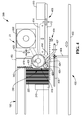
- a currency cassette replenishment terminal 399 comprises a chassis assembly, indicated generally at 400, having a base member 402 and a vertical wall 404 which stands upright on the base member 402 and extends transversely of the terminal, that is, perpendicularly to the plane of the figure.
- Tines 406 extend horizontally from the free end of the wall 404 at various points along its extent, in a direction opposite to the direction of insertion of a currency cassette, that is, from right to left as viewed in the figure.
- a prior art currency cassette 100 of the type described with reference to Figures 1 to 3 , is inserted into the terminal 399 from left to right as viewed in the figure, for currency note replenishment.
- the cassette 100 is almost completely depleted save for a small stack of notes 220 at the picking end 150.
- the picking end 150 is adjacent a currency replenishment mechanism, indicated generally at 423 (described in more detail hereinafter), which is mounted on the chassis assembly 400.
- the tines 406 enter the channels (not shown) in the cassette 100 (as described hereinabove), so as to raise the roller shutter 200 and open the pick window 210 in a similar manner to how conventional currency dispenser tines (not shown) raise the roller shutter 200.
- the cassette ratchet (not shown) is disengaged.
- the pusher plate 240 applies force to the note stack 220, via a cassette spring (not shown, but mounted beneath the floor 300 and parallel to the central rail 310) to urge the note stack towards the picking end 150.
- a terminal ratchet mechanism 408 can selectively be driven to drive the pusher plate 240 away from the pick window end 145 by a desired amount (in response to a controller (not shown) located within the terminal 399), thus selectively relieving pressure on the front of the stack 220 to permit easier loading of new notes.
- a note feeder mechanism is mounted on the chassis assembly 400.
- the mechanism 409 comprises a note input module 410, lower guide rails 412 (only one of which is visible in Figure 4 ) and upper endless conveyer belts 414 (shown schematically as a dotted line).
- the note input module 410 is at one end (the right hand end as viewed in the figure) of the guide rails 412 and conveyer belts 414. At the other end is a guide roller 416 which forms part of the currency note replenishment mechanism 423.
- the currency replenishment mechanism 423 comprises: a vacuum cylinder assembly 418; a drive motor 422; a drive belt 420; a pinch roller 426 mounted at the end of a cranked, pivotal arm 427; a turn guide 424, also mounted on the arm 427; and a release guide 428.
- the arm 427 is pivotably mounted at the end opposite to the pinch roller 426 and is urged towards the cylinder assembly 418. Both the guide roller 416 and the pinch roller 426 are driven to co-rotate with the cylinder assembly 418 (anti-clockwise as viewed in the figure).
- the pinch roller 426 is also provided with a number of radially outwardly extending, resilient flapper fingers 429 spaced equally around its outer surface.
- the cylinder assembly 418 comprises a drum-like member having a wall 419, the interior surface of which defines a central bore 421 which is connected to a vacuum pump (not shown), so as to form a vacuum chamber.
- a vacuum pump not shown
- air is sucked into the vacuum chamber through apertures (not shown) in the wall 419.
- the central bore is partitioned so that the whole bore does not need to be pumped out at any one time.
- the drive belt 420 is driven by the motor 422 and drivably connected to the cylinder assembly 418 so as to drive the cylinder assembly 418 in rotation (clockwise as viewed in Figure 4 ).
- Currency notes are supplied from the feeder mechanism 409 to the note replenishment mechanism 423 where they are picked up by the cylinder assembly 418 and taken to the currency cassette 100, there being deposited through the pick window 210 so as to join the stack of notes 220 already in the cassette 100.
- the notes are conveyed one at a time in a manner typical of ATMs using guide rail 412 and conveyer feeder mechanisms between the note input module 410 and the guide roller 416.
- the guide roller 416 is positioned adjacent to the vacuum cylinder assembly 418 so as to guide a note as it leaves the feeder mechanism closely enough to the cylinder assembly 418 that the vacuum chamber sucking action through the apertures causes the note to be grabbed by the cylinder assembly 418. This sucking action causes the note to be held against the cylinder assembly 418 as the cylinder assembly 418 is rotated.
- the turn guide 424 and pinch roller 426 ensure that the note remains held by the cylinder assembly 418. This is achieved because the turn guide 424 is arcuate in shape and radially spaced from the cylindrical assembly 418. If a note is not fully held against the cylinder assembly 418, and a leading edge of that note begins to move away from the cylinder assembly 418 then the turn guide 424 deflects the leading edge towards the cylinder assembly 418.
- the pinch roller 426, and particularly the resilient flapper fingers 429 ensure that the leading edge of the note is then directed towards the wall 419 of the cylindrical assembly 418.
- the resilient fingers 429 yield to the note as it passes the pinch roller 426.
- the note continues to rotate with the cylinder assembly 418 until its leading edge reaches the guide member 428 which is so shaped as to come between the leading edge and the cylinder assembly 418 and to prise the leading edge of the note away from the cylinder assembly 418. With the trailing edge of the note still held by the cylinder assembly 418, continued rotation of the cylinder assembly 418 drives the leading edge through the pick window 210, into the currency cassette 100.
- the sucking action is maintained throughout transport of the note around the cylinder assembly 418.
- the suction (that is, the sucking action) may be turned off when a note reaches the guide member 428 to facilitate removal of the note from the cylinder assembly 418.
- a blanking plate also referred to as a shroud
- the blanking plate may be mounted so that it does not move relative to the guide member 428 (in other words, the wall 410 would rotate relative to the fixed blanking plate so that the blanking plate always blocks those apertures that are opposite the guide member 428 but never blocks those apertures between the guide roller 416 and the pinch roller 426).
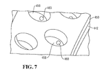
- FIG. 5 A specific embodiment of vacuum cylinder assembly is illustrated in Figures 5, 6 and 7 .
- This particular assembly comprises a drum-like member divided into two sub-assemblies 440, 441 arranged in a mirror image fashion, with each sub-assembly 440, 441 comprising a separate vacuum chamber. For the sake of clarity, only one of the sub-assemblies will be described.
- the sub-assembly 440 comprises a wall 442 with a reduced diameter centre portion 448 defining a right hand increased diameter end portion 444 and a left hand increased diameter end portion 446.
- Each increased diameter end portion 444, 446 is provided with an outer sleeve 450 made from an elastomeric material with a high coefficient of friction.
- the interior surface of the wall 442 defines a central bore 453 which serves as a vacuum chamber.
- the end of the right hand end portion 444 adjacent to the centre of the assembly 418 is fixed to a spindle 454.
- the opposite end of the left hand end portion 446 is freely rotatable about one end of a pipe elbow 456, the other end of which is connected via a hose (not shown) to a vacuum pump (not shown).
- a pulley 456 is mounted on the centre spindle 454 and the drive belt 420 from the drive motor 422 drives the pulley 456 so as to rotate the sub-assembly 440.
- Each outer sleeve 450 has a series of apertures 458 arranged in two parallel circumferential ring formations with the apertures in each ring equally spaced and offset from the apertures in the other ring.
- the pressure in the vacuum chamber 453 is reduced, air is sucked through the apertures 458, which enables the sub-assembly 440 to grab a currency note as described above.
- the aperture size is about around 0.30mm in diameter.
- the apertures are in the range of about around 0.1 to 0.50mm.
- Each outer sleeve is removably slid onto its corresponding end part 444, 446 so as to be interchangeable with other sleeves having different aperture 458 sizes and/or arrangements and/or of material with a different coefficient of friction.
- the sleeve can have apertures having a substantially cylindrical shape (common diameter along a length through the sleeve material) alternative profiles of aperture may optionally be selected.
- a 'cup like' aperture can have a relatively narrow waist close to the cylinder which flares out towards the outer surface of the sleeve. This helps reduce a volume of space in which a negative pressure should be established but helps maximise a possible holding force on a note.
- the apertures include precision drilled restrictor holes to transmit the vacuum whilst helping to prevent vacuum loss when there is no media item present.
- a currency note 472 is shown at the end of the note feeder mechanism 409, approaching the guide roller 416.
- the note 472 is shown having been guided by the guide roller 416 to the cylinder assembly 418 which has grabbed the note and rotated it past the turn guide 424 and towards the pinch roller 426.
- the note 472 is shown, with the cylinder assembly 418 having rotated further such that the release guide 428 has prised the leading edge of the note away from the cylinder assembly 418, having had its leading edge driven through the pick window, into the currency cassette 100 against the existing stack of notes 220.
- the vacuum chamber is segregated into separate chambers by one or more partition walls.
- a negative pressure may be generated in each chamber independently so that a volume to be pumped is reduced with respect to the whole volume inside the drum. This enables the negative pressure to be generated more rapidly and/or allows a smaller capacity (cheaper) pump to be utilised.
- a positive pressure can be generated in one or more chambers at selected times. This helps blow currency notes off the drum into the stack.
- FIG 11 illustrates an alternative embodiment of the present invention in many ways similar to that previously described.
- a shroud 1110 is included in the cylinder assembly 418 in the embodiment shown in Figure 11 .
- the shroud 1110 shields the apertures 458 from the negative pressure in the central bore where the shroud is located.
- the shroud does not extend so as to shield apertures used to pick up an incoming media item, move it across the pinch rollers and then deposit the item in the cassette.
- By effectively forming a seal over many of the apertures of the cylinder assembly it is easier to generate sufficient negative pressure at the apertures which remain open and which are actually utilised to transport items of media.
- shroud 1110 remains stationery and fixed in position whilst the surrounding sleeve rotates with respect to the shroud. Items of media are thus "adhered" to the rotating outer sleeve 450 by means of the negative pressure in the cylinder assembly which is communicated via apertures 458 which remain open.
- the separate parts of the vacuum assembly are modular in nature. This enables parts to be selected according to specific use. For example, a width of the outer sleeve selected can be chosen to adjust for different currency note widths or other such parameters.
- a release point is selected for where the media item is released from the rotating cylinder assembly.
- relatively stiff items of media such as new currency notes
- very limp items of media such as old, well used currency notes
- certain embodiments of the present invention can be utilised to pick items of media such as currency notes from a container such as a currency cassette rather than or in addition to selectively loading such items into the container. It will be appreciated that if items are being picked then the drum assembly is driven in an opposite way to that described hereinabove (for example, anti-clockwise).
Landscapes
- Engineering & Computer Science (AREA)
- Mechanical Engineering (AREA)
- Physics & Mathematics (AREA)
- General Physics & Mathematics (AREA)
- Sheets, Magazines, And Separation Thereof (AREA)
- Manipulator (AREA)
Applications Claiming Priority (1)
| Application Number | Priority Date | Filing Date | Title |
|---|---|---|---|
| US201213720373A | 2013-01-24 | 2013-01-24 |
Publications (3)
| Publication Number | Publication Date |
|---|---|
| EP2759504A2 true EP2759504A2 (de) | 2014-07-30 |
| EP2759504A3 EP2759504A3 (de) | 2014-09-17 |
| EP2759504B1 EP2759504B1 (de) | 2016-04-27 |
Family
ID=49230497
Family Applications (1)
| Application Number | Title | Priority Date | Filing Date |
|---|---|---|---|
| EP13184010.0A Active EP2759504B1 (de) | 2013-01-24 | 2013-09-11 | Vorrichtung zum Beladen zumindest eines Mediaobjekts in einem Mediaobjektebehälter, und Verfahren zum Beladen zumindest eines Mediaobjekts in einem Mediaobjektebehälter |
Country Status (1)
| Country | Link |
|---|---|
| EP (1) | EP2759504B1 (de) |
Cited By (2)
| Publication number | Priority date | Publication date | Assignee | Title |
|---|---|---|---|---|
| KR20160001065A (ko) * | 2014-06-26 | 2016-01-06 | 주식회사 엘지씨엔에스 | 매체처리장치 및 금융기기 |
| CN109637005A (zh) * | 2018-12-20 | 2019-04-16 | 恒银金融科技股份有限公司 | 一种纸币运输通道的换向装置 |
Family Cites Families (5)
| Publication number | Priority date | Publication date | Assignee | Title |
|---|---|---|---|---|
| US2752154A (en) * | 1955-05-02 | 1956-06-26 | Hughes Aircraft Co | Card receiving station |
| GB2108935B (en) * | 1981-11-10 | 1985-06-12 | Ncr Co | Sheet handling apparatus |
| JP2688463B2 (ja) * | 1992-07-07 | 1997-12-10 | 沖電気工業株式会社 | 紙葉類分離繰り出し集積機構 |
| JPH08245045A (ja) * | 1995-01-09 | 1996-09-24 | Fuji Xerox Co Ltd | 画像形成装置 |
| US8123222B2 (en) * | 2009-05-01 | 2012-02-28 | Pitney Bowes Inc. | Compliant conveyance system for mailpiece transport along an arcuate feed path |
-
2013
- 2013-09-11 EP EP13184010.0A patent/EP2759504B1/de active Active
Non-Patent Citations (1)
| Title |
|---|
| None |
Cited By (2)
| Publication number | Priority date | Publication date | Assignee | Title |
|---|---|---|---|---|
| KR20160001065A (ko) * | 2014-06-26 | 2016-01-06 | 주식회사 엘지씨엔에스 | 매체처리장치 및 금융기기 |
| CN109637005A (zh) * | 2018-12-20 | 2019-04-16 | 恒银金融科技股份有限公司 | 一种纸币运输通道的换向装置 |
Also Published As
| Publication number | Publication date |
|---|---|
| EP2759504A3 (de) | 2014-09-17 |
| EP2759504B1 (de) | 2016-04-27 |
Similar Documents
| Publication | Publication Date | Title |
|---|---|---|
| US9016682B2 (en) | Item location | |
| EP2693411B1 (de) | Kassettennachfüllung | |
| JPH0215451B2 (de) | ||
| CN104813376B (zh) | 用于接收和提供纸币的装置以及用于接收和提供纸币的方法 | |
| JP4992262B2 (ja) | 薬剤払出装置 | |
| CN102667879A (zh) | 自动交易装置 | |
| EP2759504B1 (de) | Vorrichtung zum Beladen zumindest eines Mediaobjekts in einem Mediaobjektebehälter, und Verfahren zum Beladen zumindest eines Mediaobjekts in einem Mediaobjektebehälter | |
| KR101665609B1 (ko) | 금융 자동화기기용 회수매체 저장 카세트 | |
| KR100966675B1 (ko) | 금융자동화기기 | |
| EP2400469A1 (de) | Vorrichtung zur papierblatthandhabung | |
| JP6227397B2 (ja) | 紙幣処理装置 | |
| US8733530B2 (en) | Item recycling | |
| US20230166917A1 (en) | Lid transport conveyor and a transport and decontamination machine | |
| JP2009217512A (ja) | 紙葉類取扱装置 | |
| KR101094627B1 (ko) | 매체자동지급기의 접객장치 | |
| US20200372765A1 (en) | Automated teller machine | |
| JPWO2017072881A1 (ja) | 紙葉類格納装置及び紙葉類格納装置の格納方法 | |
| KR101120867B1 (ko) | 금융자동화기기 | |
| CN107004322B (zh) | 纸币处理装置 | |
| WO2007068888A1 (en) | Media pick unit | |
| KR102030513B1 (ko) | 지폐류 입출금장치 | |
| JPH08335287A (ja) | 紙幣処理システム、係員専用自動機、サービス用自動機 | |
| JPS647932B2 (de) | ||
| JP3850304B2 (ja) | 紙幣入出金機 | |
| JPH0215450B2 (de) |
Legal Events
| Date | Code | Title | Description |
|---|---|---|---|
| PUAI | Public reference made under article 153(3) epc to a published international application that has entered the european phase |
Free format text: ORIGINAL CODE: 0009012 |
|
| 17P | Request for examination filed |
Effective date: 20130911 |
|
| AK | Designated contracting states |
Kind code of ref document: A2 Designated state(s): AL AT BE BG CH CY CZ DE DK EE ES FI FR GB GR HR HU IE IS IT LI LT LU LV MC MK MT NL NO PL PT RO RS SE SI SK SM TR |
|
| AX | Request for extension of the european patent |
Extension state: BA ME |
|
| PUAL | Search report despatched |
Free format text: ORIGINAL CODE: 0009013 |
|
| AK | Designated contracting states |
Kind code of ref document: A3 Designated state(s): AL AT BE BG CH CY CZ DE DK EE ES FI FR GB GR HR HU IE IS IT LI LT LU LV MC MK MT NL NO PL PT RO RS SE SI SK SM TR |
|
| AX | Request for extension of the european patent |
Extension state: BA ME |
|
| RIC1 | Information provided on ipc code assigned before grant |
Ipc: B65H 31/22 20060101ALI20140811BHEP Ipc: B65H 29/24 20060101AFI20140811BHEP Ipc: B65H 29/56 20060101ALI20140811BHEP Ipc: B65H 31/06 20060101ALI20140811BHEP |
|
| R17P | Request for examination filed (corrected) |
Effective date: 20150317 |
|
| RBV | Designated contracting states (corrected) |
Designated state(s): AL AT BE BG CH CY CZ DE DK EE ES FI FR GB GR HR HU IE IS IT LI LT LU LV MC MK MT NL NO PL PT RO RS SE SI SK SM TR |
|
| 17Q | First examination report despatched |
Effective date: 20150422 |
|
| RIC1 | Information provided on ipc code assigned before grant |
Ipc: B65H 29/56 20060101ALI20150729BHEP Ipc: B65H 29/24 20060101AFI20150729BHEP Ipc: G07D 11/00 20060101ALI20150729BHEP Ipc: B65H 31/06 20060101ALI20150729BHEP Ipc: B65H 1/02 20060101ALI20150729BHEP Ipc: B65H 31/22 20060101ALI20150729BHEP |
|
| GRAP | Despatch of communication of intention to grant a patent |
Free format text: ORIGINAL CODE: EPIDOSNIGR1 |
|
| INTG | Intention to grant announced |
Effective date: 20150909 |
|
| GRAS | Grant fee paid |
Free format text: ORIGINAL CODE: EPIDOSNIGR3 |
|
| GRAA | (expected) grant |
Free format text: ORIGINAL CODE: 0009210 |
|
| AK | Designated contracting states |
Kind code of ref document: B1 Designated state(s): AL AT BE BG CH CY CZ DE DK EE ES FI FR GB GR HR HU IE IS IT LI LT LU LV MC MK MT NL NO PL PT RO RS SE SI SK SM TR |
|
| REG | Reference to a national code |
Ref country code: GB Ref legal event code: FG4D |
|
| REG | Reference to a national code |
Ref country code: CH Ref legal event code: EP |
|
| REG | Reference to a national code |
Ref country code: AT Ref legal event code: REF Ref document number: 794554 Country of ref document: AT Kind code of ref document: T Effective date: 20160515 |
|
| REG | Reference to a national code |
Ref country code: DE Ref legal event code: R084 Ref document number: 602013006911 Country of ref document: DE Ref country code: IE Ref legal event code: FG4D |
|
| REG | Reference to a national code |
Ref country code: GB Ref legal event code: 746 Effective date: 20160518 |
|
| REG | Reference to a national code |
Ref country code: DE Ref legal event code: R096 Ref document number: 602013006911 Country of ref document: DE |
|
| REG | Reference to a national code |
Ref country code: LT Ref legal event code: MG4D |
|
| REG | Reference to a national code |
Ref country code: NL Ref legal event code: MP Effective date: 20160427 |
|
| REG | Reference to a national code |
Ref country code: AT Ref legal event code: MK05 Ref document number: 794554 Country of ref document: AT Kind code of ref document: T Effective date: 20160427 |
|
| REG | Reference to a national code |
Ref country code: FR Ref legal event code: PLFP Year of fee payment: 4 |
|
| PG25 | Lapsed in a contracting state [announced via postgrant information from national office to epo] |
Ref country code: NL Free format text: LAPSE BECAUSE OF FAILURE TO SUBMIT A TRANSLATION OF THE DESCRIPTION OR TO PAY THE FEE WITHIN THE PRESCRIBED TIME-LIMIT Effective date: 20160427 |
|
| PG25 | Lapsed in a contracting state [announced via postgrant information from national office to epo] |
Ref country code: FI Free format text: LAPSE BECAUSE OF FAILURE TO SUBMIT A TRANSLATION OF THE DESCRIPTION OR TO PAY THE FEE WITHIN THE PRESCRIBED TIME-LIMIT Effective date: 20160427 Ref country code: PL Free format text: LAPSE BECAUSE OF FAILURE TO SUBMIT A TRANSLATION OF THE DESCRIPTION OR TO PAY THE FEE WITHIN THE PRESCRIBED TIME-LIMIT Effective date: 20160427 Ref country code: NO Free format text: LAPSE BECAUSE OF FAILURE TO SUBMIT A TRANSLATION OF THE DESCRIPTION OR TO PAY THE FEE WITHIN THE PRESCRIBED TIME-LIMIT Effective date: 20160727 Ref country code: LT Free format text: LAPSE BECAUSE OF FAILURE TO SUBMIT A TRANSLATION OF THE DESCRIPTION OR TO PAY THE FEE WITHIN THE PRESCRIBED TIME-LIMIT Effective date: 20160427 |
|
| PG25 | Lapsed in a contracting state [announced via postgrant information from national office to epo] |
Ref country code: PT Free format text: LAPSE BECAUSE OF FAILURE TO SUBMIT A TRANSLATION OF THE DESCRIPTION OR TO PAY THE FEE WITHIN THE PRESCRIBED TIME-LIMIT Effective date: 20160829 Ref country code: SE Free format text: LAPSE BECAUSE OF FAILURE TO SUBMIT A TRANSLATION OF THE DESCRIPTION OR TO PAY THE FEE WITHIN THE PRESCRIBED TIME-LIMIT Effective date: 20160427 Ref country code: LV Free format text: LAPSE BECAUSE OF FAILURE TO SUBMIT A TRANSLATION OF THE DESCRIPTION OR TO PAY THE FEE WITHIN THE PRESCRIBED TIME-LIMIT Effective date: 20160427 Ref country code: HR Free format text: LAPSE BECAUSE OF FAILURE TO SUBMIT A TRANSLATION OF THE DESCRIPTION OR TO PAY THE FEE WITHIN THE PRESCRIBED TIME-LIMIT Effective date: 20160427 Ref country code: RS Free format text: LAPSE BECAUSE OF FAILURE TO SUBMIT A TRANSLATION OF THE DESCRIPTION OR TO PAY THE FEE WITHIN THE PRESCRIBED TIME-LIMIT Effective date: 20160427 Ref country code: GR Free format text: LAPSE BECAUSE OF FAILURE TO SUBMIT A TRANSLATION OF THE DESCRIPTION OR TO PAY THE FEE WITHIN THE PRESCRIBED TIME-LIMIT Effective date: 20160728 Ref country code: AT Free format text: LAPSE BECAUSE OF FAILURE TO SUBMIT A TRANSLATION OF THE DESCRIPTION OR TO PAY THE FEE WITHIN THE PRESCRIBED TIME-LIMIT Effective date: 20160427 Ref country code: ES Free format text: LAPSE BECAUSE OF FAILURE TO SUBMIT A TRANSLATION OF THE DESCRIPTION OR TO PAY THE FEE WITHIN THE PRESCRIBED TIME-LIMIT Effective date: 20160427 |
|
| PG25 | Lapsed in a contracting state [announced via postgrant information from national office to epo] |
Ref country code: BE Free format text: LAPSE BECAUSE OF FAILURE TO SUBMIT A TRANSLATION OF THE DESCRIPTION OR TO PAY THE FEE WITHIN THE PRESCRIBED TIME-LIMIT Effective date: 20160427 Ref country code: IT Free format text: LAPSE BECAUSE OF FAILURE TO SUBMIT A TRANSLATION OF THE DESCRIPTION OR TO PAY THE FEE WITHIN THE PRESCRIBED TIME-LIMIT Effective date: 20160427 |
|
| REG | Reference to a national code |
Ref country code: DE Ref legal event code: R097 Ref document number: 602013006911 Country of ref document: DE |
|
| PG25 | Lapsed in a contracting state [announced via postgrant information from national office to epo] |
Ref country code: DK Free format text: LAPSE BECAUSE OF FAILURE TO SUBMIT A TRANSLATION OF THE DESCRIPTION OR TO PAY THE FEE WITHIN THE PRESCRIBED TIME-LIMIT Effective date: 20160427 Ref country code: RO Free format text: LAPSE BECAUSE OF FAILURE TO SUBMIT A TRANSLATION OF THE DESCRIPTION OR TO PAY THE FEE WITHIN THE PRESCRIBED TIME-LIMIT Effective date: 20160427 Ref country code: CZ Free format text: LAPSE BECAUSE OF FAILURE TO SUBMIT A TRANSLATION OF THE DESCRIPTION OR TO PAY THE FEE WITHIN THE PRESCRIBED TIME-LIMIT Effective date: 20160427 Ref country code: SK Free format text: LAPSE BECAUSE OF FAILURE TO SUBMIT A TRANSLATION OF THE DESCRIPTION OR TO PAY THE FEE WITHIN THE PRESCRIBED TIME-LIMIT Effective date: 20160427 Ref country code: EE Free format text: LAPSE BECAUSE OF FAILURE TO SUBMIT A TRANSLATION OF THE DESCRIPTION OR TO PAY THE FEE WITHIN THE PRESCRIBED TIME-LIMIT Effective date: 20160427 |
|
| PG25 | Lapsed in a contracting state [announced via postgrant information from national office to epo] |
Ref country code: SM Free format text: LAPSE BECAUSE OF FAILURE TO SUBMIT A TRANSLATION OF THE DESCRIPTION OR TO PAY THE FEE WITHIN THE PRESCRIBED TIME-LIMIT Effective date: 20160427 |
|
| PLBE | No opposition filed within time limit |
Free format text: ORIGINAL CODE: 0009261 |
|
| STAA | Information on the status of an ep patent application or granted ep patent |
Free format text: STATUS: NO OPPOSITION FILED WITHIN TIME LIMIT |
|
| 26N | No opposition filed |
Effective date: 20170130 |
|
| PG25 | Lapsed in a contracting state [announced via postgrant information from national office to epo] |
Ref country code: MC Free format text: LAPSE BECAUSE OF FAILURE TO SUBMIT A TRANSLATION OF THE DESCRIPTION OR TO PAY THE FEE WITHIN THE PRESCRIBED TIME-LIMIT Effective date: 20160427 |
|
| REG | Reference to a national code |
Ref country code: CH Ref legal event code: PL |
|
| PG25 | Lapsed in a contracting state [announced via postgrant information from national office to epo] |
Ref country code: SI Free format text: LAPSE BECAUSE OF FAILURE TO SUBMIT A TRANSLATION OF THE DESCRIPTION OR TO PAY THE FEE WITHIN THE PRESCRIBED TIME-LIMIT Effective date: 20160427 |
|
| REG | Reference to a national code |
Ref country code: IE Ref legal event code: MM4A |
|
| PG25 | Lapsed in a contracting state [announced via postgrant information from national office to epo] |
Ref country code: LI Free format text: LAPSE BECAUSE OF NON-PAYMENT OF DUE FEES Effective date: 20160930 Ref country code: IE Free format text: LAPSE BECAUSE OF NON-PAYMENT OF DUE FEES Effective date: 20160911 Ref country code: CH Free format text: LAPSE BECAUSE OF NON-PAYMENT OF DUE FEES Effective date: 20160930 |
|
| PG25 | Lapsed in a contracting state [announced via postgrant information from national office to epo] |
Ref country code: LU Free format text: LAPSE BECAUSE OF NON-PAYMENT OF DUE FEES Effective date: 20160911 |
|
| REG | Reference to a national code |
Ref country code: FR Ref legal event code: PLFP Year of fee payment: 5 |
|
| PG25 | Lapsed in a contracting state [announced via postgrant information from national office to epo] |
Ref country code: HU Free format text: LAPSE BECAUSE OF FAILURE TO SUBMIT A TRANSLATION OF THE DESCRIPTION OR TO PAY THE FEE WITHIN THE PRESCRIBED TIME-LIMIT; INVALID AB INITIO Effective date: 20130911 |
|
| PG25 | Lapsed in a contracting state [announced via postgrant information from national office to epo] |
Ref country code: MT Free format text: LAPSE BECAUSE OF NON-PAYMENT OF DUE FEES Effective date: 20160930 Ref country code: IS Free format text: LAPSE BECAUSE OF FAILURE TO SUBMIT A TRANSLATION OF THE DESCRIPTION OR TO PAY THE FEE WITHIN THE PRESCRIBED TIME-LIMIT Effective date: 20160427 Ref country code: CY Free format text: LAPSE BECAUSE OF FAILURE TO SUBMIT A TRANSLATION OF THE DESCRIPTION OR TO PAY THE FEE WITHIN THE PRESCRIBED TIME-LIMIT Effective date: 20160427 Ref country code: MK Free format text: LAPSE BECAUSE OF FAILURE TO SUBMIT A TRANSLATION OF THE DESCRIPTION OR TO PAY THE FEE WITHIN THE PRESCRIBED TIME-LIMIT Effective date: 20160427 |
|
| PG25 | Lapsed in a contracting state [announced via postgrant information from national office to epo] |
Ref country code: BG Free format text: LAPSE BECAUSE OF FAILURE TO SUBMIT A TRANSLATION OF THE DESCRIPTION OR TO PAY THE FEE WITHIN THE PRESCRIBED TIME-LIMIT Effective date: 20160427 |
|
| REG | Reference to a national code |
Ref country code: FR Ref legal event code: PLFP Year of fee payment: 6 |
|
| PG25 | Lapsed in a contracting state [announced via postgrant information from national office to epo] |
Ref country code: AL Free format text: LAPSE BECAUSE OF FAILURE TO SUBMIT A TRANSLATION OF THE DESCRIPTION OR TO PAY THE FEE WITHIN THE PRESCRIBED TIME-LIMIT Effective date: 20160427 Ref country code: TR Free format text: LAPSE BECAUSE OF FAILURE TO SUBMIT A TRANSLATION OF THE DESCRIPTION OR TO PAY THE FEE WITHIN THE PRESCRIBED TIME-LIMIT Effective date: 20160427 |
|
| REG | Reference to a national code |
Ref country code: DE Ref legal event code: R081 Ref document number: 602013006911 Country of ref document: DE Owner name: CARDTRONICS USA, INC. (GESELLSCHAFT NACH DEN G, US Free format text: FORMER OWNER: NCR CORP., DULUTH, GA., US Ref country code: DE Ref legal event code: R082 Ref document number: 602013006911 Country of ref document: DE Representative=s name: V. BEZOLD & PARTNER PATENTANWAELTE - PARTG MBB, DE Ref country code: DE Ref legal event code: R081 Ref document number: 602013006911 Country of ref document: DE Owner name: NCR CORPORATION, ATLANTA, US Free format text: FORMER OWNER: NCR CORP., DULUTH, GA., US |
|
| P01 | Opt-out of the competence of the unified patent court (upc) registered |
Effective date: 20230506 |
|
| REG | Reference to a national code |
Ref country code: DE Ref legal event code: R081 Ref document number: 602013006911 Country of ref document: DE Owner name: CARDTRONICS USA, INC. (GESELLSCHAFT NACH DEN G, US Free format text: FORMER OWNER: NCR CORPORATION, ATLANTA, GA, US |
|
| PGFP | Annual fee paid to national office [announced via postgrant information from national office to epo] |
Ref country code: DE Payment date: 20250929 Year of fee payment: 13 |
|
| PGFP | Annual fee paid to national office [announced via postgrant information from national office to epo] |
Ref country code: GB Payment date: 20250929 Year of fee payment: 13 |
|
| PGFP | Annual fee paid to national office [announced via postgrant information from national office to epo] |
Ref country code: FR Payment date: 20250925 Year of fee payment: 13 |