EP2758276B1 - Säulenabdeckung für kraftfahrzeuge - Google Patents
Säulenabdeckung für kraftfahrzeuge Download PDFInfo
- Publication number
- EP2758276B1 EP2758276B1 EP12753507.8A EP12753507A EP2758276B1 EP 2758276 B1 EP2758276 B1 EP 2758276B1 EP 12753507 A EP12753507 A EP 12753507A EP 2758276 B1 EP2758276 B1 EP 2758276B1
- Authority
- EP
- European Patent Office
- Prior art keywords
- covering according
- pillar covering
- window guide
- mounting element
- polymeric
- Prior art date
- Legal status (The legal status is an assumption and is not a legal conclusion. Google has not performed a legal analysis and makes no representation as to the accuracy of the status listed.)
- Active
Links
- 239000004417 polycarbonate Substances 0.000 claims description 15
- 229920000515 polycarbonate Polymers 0.000 claims description 15
- -1 polyethylene Polymers 0.000 claims description 9
- 239000000203 mixture Substances 0.000 claims description 8
- 238000007789 sealing Methods 0.000 claims description 7
- 229920001577 copolymer Polymers 0.000 claims description 6
- 229920003229 poly(methyl methacrylate) Polymers 0.000 claims description 6
- 229920000139 polyethylene terephthalate Polymers 0.000 claims description 5
- 239000005020 polyethylene terephthalate Substances 0.000 claims description 5
- 230000003014 reinforcing effect Effects 0.000 claims description 5
- 239000004698 Polyethylene Substances 0.000 claims description 4
- 239000004743 Polypropylene Substances 0.000 claims description 4
- 239000004676 acrylonitrile butadiene styrene Substances 0.000 claims description 4
- 229920000058 polyacrylate Polymers 0.000 claims description 4
- 229920000573 polyethylene Polymers 0.000 claims description 4
- 229920000642 polymer Polymers 0.000 claims description 4
- 239000004926 polymethyl methacrylate Substances 0.000 claims description 4
- 229920001155 polypropylene Polymers 0.000 claims description 4
- 229920000728 polyester Polymers 0.000 claims description 3
- 229920000049 Carbon (fiber) Polymers 0.000 claims description 2
- 239000004952 Polyamide Substances 0.000 claims description 2
- 239000005062 Polybutadiene Substances 0.000 claims description 2
- 239000004793 Polystyrene Substances 0.000 claims description 2
- 238000003848 UV Light-Curing Methods 0.000 claims description 2
- XECAHXYUAAWDEL-UHFFFAOYSA-N acrylonitrile butadiene styrene Chemical compound C=CC=C.C=CC#N.C=CC1=CC=CC=C1 XECAHXYUAAWDEL-UHFFFAOYSA-N 0.000 claims description 2
- 229920000122 acrylonitrile butadiene styrene Polymers 0.000 claims description 2
- 239000004917 carbon fiber Substances 0.000 claims description 2
- 239000002734 clay mineral Substances 0.000 claims description 2
- 238000000576 coating method Methods 0.000 claims description 2
- 239000000835 fiber Substances 0.000 claims description 2
- 239000003365 glass fiber Substances 0.000 claims description 2
- 239000011256 inorganic filler Substances 0.000 claims description 2
- 239000012766 organic filler Substances 0.000 claims description 2
- 229920002647 polyamide Polymers 0.000 claims description 2
- 229920002857 polybutadiene Polymers 0.000 claims description 2
- 229920000193 polymethacrylate Polymers 0.000 claims description 2
- 229920005554 polynitrile Polymers 0.000 claims description 2
- 229920001296 polysiloxane Polymers 0.000 claims description 2
- 229920002223 polystyrene Polymers 0.000 claims description 2
- 229920002635 polyurethane Polymers 0.000 claims description 2
- 239000004814 polyurethane Substances 0.000 claims description 2
- 150000004760 silicates Chemical class 0.000 claims description 2
- 229920000638 styrene acrylonitrile Polymers 0.000 claims description 2
- 239000011145 styrene acrylonitrile resin Substances 0.000 claims description 2
- 239000010457 zeolite Substances 0.000 claims description 2
- 229920001707 polybutylene terephthalate Polymers 0.000 claims 3
- VYPSYNLAJGMNEJ-UHFFFAOYSA-N Silicium dioxide Chemical compound O=[Si]=O VYPSYNLAJGMNEJ-UHFFFAOYSA-N 0.000 claims 2
- GWEVSGVZZGPLCZ-UHFFFAOYSA-N Titan oxide Chemical compound O=[Ti]=O GWEVSGVZZGPLCZ-UHFFFAOYSA-N 0.000 claims 2
- 229920006942 ABS/PC Polymers 0.000 claims 1
- PNEYBMLMFCGWSK-UHFFFAOYSA-N aluminium oxide Inorganic materials [O-2].[O-2].[O-2].[Al+3].[Al+3] PNEYBMLMFCGWSK-UHFFFAOYSA-N 0.000 claims 1
- 239000011324 bead Substances 0.000 claims 1
- 239000011248 coating agent Substances 0.000 claims 1
- 229910052681 coesite Inorganic materials 0.000 claims 1
- 229910052593 corundum Inorganic materials 0.000 claims 1
- 229910052906 cristobalite Inorganic materials 0.000 claims 1
- 239000011521 glass Substances 0.000 claims 1
- 239000000377 silicon dioxide Substances 0.000 claims 1
- 229910052682 stishovite Inorganic materials 0.000 claims 1
- 238000001029 thermal curing Methods 0.000 claims 1
- 229910052905 tridymite Inorganic materials 0.000 claims 1
- 229910001845 yogo sapphire Inorganic materials 0.000 claims 1
- 239000000463 material Substances 0.000 description 18
- 238000001746 injection moulding Methods 0.000 description 7
- 238000001816 cooling Methods 0.000 description 5
- 229920003023 plastic Polymers 0.000 description 5
- 239000004033 plastic Substances 0.000 description 5
- 230000007423 decrease Effects 0.000 description 4
- 230000003287 optical effect Effects 0.000 description 4
- 230000003716 rejuvenation Effects 0.000 description 4
- 238000002347 injection Methods 0.000 description 3
- 239000007924 injection Substances 0.000 description 3
- 238000004519 manufacturing process Methods 0.000 description 3
- 230000003763 resistance to breakage Effects 0.000 description 3
- CURLTUGMZLYLDI-UHFFFAOYSA-N Carbon dioxide Chemical compound O=C=O CURLTUGMZLYLDI-UHFFFAOYSA-N 0.000 description 2
- 230000001419 dependent effect Effects 0.000 description 2
- 239000000945 filler Substances 0.000 description 2
- 230000001788 irregular Effects 0.000 description 2
- 239000002184 metal Substances 0.000 description 2
- 229910052751 metal Inorganic materials 0.000 description 2
- 238000000034 method Methods 0.000 description 2
- 238000000465 moulding Methods 0.000 description 2
- 239000011241 protective layer Substances 0.000 description 2
- 239000000126 substance Substances 0.000 description 2
- 239000013585 weight reducing agent Substances 0.000 description 2
- 229910018072 Al 2 O 3 Inorganic materials 0.000 description 1
- 229920000271 Kevlar® Polymers 0.000 description 1
- 229910004298 SiO 2 Inorganic materials 0.000 description 1
- 229910000831 Steel Inorganic materials 0.000 description 1
- 229910010413 TiO 2 Inorganic materials 0.000 description 1
- NIXOWILDQLNWCW-UHFFFAOYSA-N acrylic acid group Chemical group C(C=C)(=O)O NIXOWILDQLNWCW-UHFFFAOYSA-N 0.000 description 1
- 230000006978 adaptation Effects 0.000 description 1
- 229920003235 aromatic polyamide Polymers 0.000 description 1
- 230000033228 biological regulation Effects 0.000 description 1
- 230000015572 biosynthetic process Effects 0.000 description 1
- QXJJQWWVWRCVQT-UHFFFAOYSA-K calcium;sodium;phosphate Chemical compound [Na+].[Ca+2].[O-]P([O-])([O-])=O QXJJQWWVWRCVQT-UHFFFAOYSA-K 0.000 description 1
- 229910002092 carbon dioxide Inorganic materials 0.000 description 1
- 239000001569 carbon dioxide Substances 0.000 description 1
- 238000000748 compression moulding Methods 0.000 description 1
- 238000006073 displacement reaction Methods 0.000 description 1
- 238000005265 energy consumption Methods 0.000 description 1
- 239000000446 fuel Substances 0.000 description 1
- 230000005484 gravity Effects 0.000 description 1
- 239000003673 groundwater Substances 0.000 description 1
- 230000017525 heat dissipation Effects 0.000 description 1
- 238000009434 installation Methods 0.000 description 1
- 239000004761 kevlar Substances 0.000 description 1
- 239000004922 lacquer Substances 0.000 description 1
- 238000012417 linear regression Methods 0.000 description 1
- 150000002739 metals Chemical class 0.000 description 1
- 230000005855 radiation Effects 0.000 description 1
- 239000011342 resin composition Substances 0.000 description 1
- 230000006641 stabilisation Effects 0.000 description 1
- 238000011105 stabilization Methods 0.000 description 1
- 239000007858 starting material Substances 0.000 description 1
- 239000010959 steel Substances 0.000 description 1
- 239000012815 thermoplastic material Substances 0.000 description 1
Images


Classifications
-
- B—PERFORMING OPERATIONS; TRANSPORTING
- B62—LAND VEHICLES FOR TRAVELLING OTHERWISE THAN ON RAILS
- B62D—MOTOR VEHICLES; TRAILERS
- B62D25/00—Superstructure or monocoque structure sub-units; Parts or details thereof not otherwise provided for
- B62D25/04—Door pillars ; windshield pillars
-
- B—PERFORMING OPERATIONS; TRANSPORTING
- B60—VEHICLES IN GENERAL
- B60R—VEHICLES, VEHICLE FITTINGS, OR VEHICLE PARTS, NOT OTHERWISE PROVIDED FOR
- B60R13/00—Elements for body-finishing, identifying, or decorating; Arrangements or adaptations for advertising purposes
- B60R13/02—Internal Trim mouldings ; Internal Ledges; Wall liners for passenger compartments; Roof liners
-
- B—PERFORMING OPERATIONS; TRANSPORTING
- B60—VEHICLES IN GENERAL
- B60R—VEHICLES, VEHICLE FITTINGS, OR VEHICLE PARTS, NOT OTHERWISE PROVIDED FOR
- B60R13/00—Elements for body-finishing, identifying, or decorating; Arrangements or adaptations for advertising purposes
- B60R13/04—External Ornamental or guard strips; Ornamental inscriptive devices thereon
-
- B—PERFORMING OPERATIONS; TRANSPORTING
- B29—WORKING OF PLASTICS; WORKING OF SUBSTANCES IN A PLASTIC STATE IN GENERAL
- B29C—SHAPING OR JOINING OF PLASTICS; SHAPING OF MATERIAL IN A PLASTIC STATE, NOT OTHERWISE PROVIDED FOR; AFTER-TREATMENT OF THE SHAPED PRODUCTS, e.g. REPAIRING
- B29C45/00—Injection moulding, i.e. forcing the required volume of moulding material through a nozzle into a closed mould; Apparatus therefor
-
- B—PERFORMING OPERATIONS; TRANSPORTING
- B29—WORKING OF PLASTICS; WORKING OF SUBSTANCES IN A PLASTIC STATE IN GENERAL
- B29C—SHAPING OR JOINING OF PLASTICS; SHAPING OF MATERIAL IN A PLASTIC STATE, NOT OTHERWISE PROVIDED FOR; AFTER-TREATMENT OF THE SHAPED PRODUCTS, e.g. REPAIRING
- B29C45/00—Injection moulding, i.e. forcing the required volume of moulding material through a nozzle into a closed mould; Apparatus therefor
- B29C45/16—Making multilayered or multicoloured articles
-
- B—PERFORMING OPERATIONS; TRANSPORTING
- B60—VEHICLES IN GENERAL
- B60J—WINDOWS, WINDSCREENS, NON-FIXED ROOFS, DOORS, OR SIMILAR DEVICES FOR VEHICLES; REMOVABLE EXTERNAL PROTECTIVE COVERINGS SPECIALLY ADAPTED FOR VEHICLES
- B60J5/00—Doors
- B60J5/04—Doors arranged at the vehicle sides
-
- B—PERFORMING OPERATIONS; TRANSPORTING
- B29—WORKING OF PLASTICS; WORKING OF SUBSTANCES IN A PLASTIC STATE IN GENERAL
- B29C—SHAPING OR JOINING OF PLASTICS; SHAPING OF MATERIAL IN A PLASTIC STATE, NOT OTHERWISE PROVIDED FOR; AFTER-TREATMENT OF THE SHAPED PRODUCTS, e.g. REPAIRING
- B29C45/00—Injection moulding, i.e. forcing the required volume of moulding material through a nozzle into a closed mould; Apparatus therefor
- B29C45/0025—Preventing defects on the moulded article, e.g. weld lines, shrinkage marks
- B29C2045/0043—Preventing defects on the moulded article, e.g. weld lines, shrinkage marks preventing shrinkage by reducing the wall thickness of the moulded article
-
- B—PERFORMING OPERATIONS; TRANSPORTING
- B29—WORKING OF PLASTICS; WORKING OF SUBSTANCES IN A PLASTIC STATE IN GENERAL
- B29C—SHAPING OR JOINING OF PLASTICS; SHAPING OF MATERIAL IN A PLASTIC STATE, NOT OTHERWISE PROVIDED FOR; AFTER-TREATMENT OF THE SHAPED PRODUCTS, e.g. REPAIRING
- B29C45/00—Injection moulding, i.e. forcing the required volume of moulding material through a nozzle into a closed mould; Apparatus therefor
- B29C45/16—Making multilayered or multicoloured articles
- B29C2045/1682—Making multilayered or multicoloured articles preventing defects
-
- B—PERFORMING OPERATIONS; TRANSPORTING
- B29—WORKING OF PLASTICS; WORKING OF SUBSTANCES IN A PLASTIC STATE IN GENERAL
- B29C—SHAPING OR JOINING OF PLASTICS; SHAPING OF MATERIAL IN A PLASTIC STATE, NOT OTHERWISE PROVIDED FOR; AFTER-TREATMENT OF THE SHAPED PRODUCTS, e.g. REPAIRING
- B29C45/00—Injection moulding, i.e. forcing the required volume of moulding material through a nozzle into a closed mould; Apparatus therefor
- B29C45/0025—Preventing defects on the moulded article, e.g. weld lines, shrinkage marks
-
- B—PERFORMING OPERATIONS; TRANSPORTING
- B29—WORKING OF PLASTICS; WORKING OF SUBSTANCES IN A PLASTIC STATE IN GENERAL
- B29L—INDEXING SCHEME ASSOCIATED WITH SUBCLASS B29C, RELATING TO PARTICULAR ARTICLES
- B29L2031/00—Other particular articles
- B29L2031/30—Vehicles, e.g. ships or aircraft, or body parts thereof
- B29L2031/3005—Body finishings
Definitions
- the invention relates to a column cover for motor vehicles and their use.
- Moldings made of polymeric materials can be produced in virtually any desired shape and geometry.
- Special high-performance plastics such as aramids, for example Kevlar, have very high strengths and stabilities.
- DE 196 33 959 A1 discloses a molded article of a carrier and an outer decorative film.
- the outer film has a decorative and a protective layer, wherein the protective layer consists of a photopolymerizable resin composition.
- WO 2006/094484 A1 discloses a method for producing a two-component sheet-like plastic body panel.
- the first component is a transparent polycarbonate and the second component is an opaque polycarbonate.
- DE 197 22 551 A1 discloses a method for producing plastic parts in the two-component injection molding process.
- EP 1 695 808 A1 discloses a trim part for a motor vehicle, for example, a trim strip.
- the trim part comprises a carrier part made of a thermoplastic material and a cover part.
- the trim part is preferably produced by a multi-component injection molding process.
- EP 2 272 718 A1 discloses a column cover according to the preamble of claim 1.
- the invention has the object to provide a workpiece of at least two different materials, which has a uniform edge region with simultaneously different material shrinkage behavior.
- the column cover for vehicles according to the invention comprises at least one polymeric carrier part with an integrated window guide bar and a taper between the polymeric carrier part and the window guide bar.
- the preferably molded window guide web depends on the actual carrier part and the exact dimensioning depends on the geometry of the matching workpiece on the vehicle.
- the window guide web is preferably approximately L-shaped and preferably has an angle of 45 ° to 135 ° to the base surface of the polymeric carrier part in the protruding area.
- the window guide web preferably has a length of 10 mm to 20 mm in each of the two partial webs.
- the term "tapered" in the sense of the invention means a linear or gradual decrease in the thickness of the window guide web adjacent or adjacent to the base of the polymeric support member.
- the window guide web is preferably made of the same material as the polymeric carrier part and is preferably produced by molding tools with corresponding recesses in the injection molding process.
- the polymeric backing provides the stability of the column cover and includes polymeric materials having the highest possible strength, scratch resistance, impact strength or impact strength and lower tendency to break.
- the polymeric carrier part preferably comprises a mounting element.
- the mounting element is preferably F-shaped. The exact shape of the mounting element depends on the corresponding counterpart of the body.
- a polymeric cover part is connected via a contact surface.
- the term "contact surface” describes the interface between the polymeric support member and the polymeric cover part.
- the polymeric cover part can take on both decorative functions and functions in the field of tool resistance. Examples include surfaces or coatings that increase the weathering, UV or chemical resistance of the column cover.
- the polymeric carrier part and the polymeric cover part form at least one common rounded end piece.
- tail in the context of the invention preferably refers to a terminal region in which the total thickness of polymeric support member and polymeric cover member or their individual thicknesses gradually or linearly decrease.
- the contact area between the polymeric support member and the polymeric cover member extends within the endpiece over a length of at least 1 mm (measured from the edge of the tail) at an average angle of 5 ° to 60 ° (degrees) to the polymeric support member or away from the polymeric support member (Above or below the average axis of the contact surface between the polymeric support part and the polymeric cover part outside of the / e) / e).
- the contact surface can be linear or curved.
- the contact surface extends within the tail preferably over a length of 2 mm to 20 mm at an average angle of 10 ° to 50 °.
- the displacement of the contact surface from the average axis of the contact surface between the polymeric support member and the polymeric cover member causes thinning of the portion of polymeric support member or polymeric cover member in the tail.
- This thinning of a material component of the polymeric support member or polymeric cover allows adaptation of the shrinkage and cooling behavior in the tail. In this way, the formation of optical distortions in the tail is prevented.
- the mass of this can be reduced in the region of the tail and so allow an overall faster cooling at a lower mass, preferably simultaneously with the polymeric cover part.
- This edge geometry according to the invention can be formed circumferentially on all common edges of the polymeric support part and the polymeric cover part within the column cover or only on individual component edges.
- the taper preferably tapers from 1 mm to 4 mm to 0.2 mm to 2 mm. These dimensions allow high stability within the taper while minimizing weight.
- a stiffening rib is preferably within the taper, more preferably, a plurality of stiffening ribs are mounted within the taper.
- the stiffening ribs significantly increase the stability and resistance to breakage of the window guide bar and are arranged particularly space-saving within the taper.
- the polymeric carrier part preferably comprises polyethylene (PE), polycarbonates (PC), polypropylene (PP), polystyrene, polybutadiene, polynitriles, polyesters, polyurethanes, polymethyl methacrylates, polyacrylates, polyesters, polyamides, polyethylene terephthalate (PET), preferably acrylonitrile-butadiene-styrene ( ABS), acrylic ester-styrene-acrylonitrile (ASA), acrylonitrile-butadiene-styrene-polycarbonate (ABS + PC) and / or copolymers or mixtures thereof.
- PE polyethylene
- PC polycarbonates
- PP polypropylene
- polystyrene polybutadiene
- polynitriles polynitriles
- polyesters polyurethanes
- polymethyl methacrylates polyacrylates
- polyesters polyamides
- PET polyethylene terephthalate
- ABS acrylonitrile-butad
- the window guide web and / or the mounting element preferably have a wall thickness thinning to 0.5 mm to 3 mm on the surface, wherein the thinned base wall of the window guide web and / or the mounting element preferably by a honeycomb, circular or polygonal raised surface structure, particularly preferably a hexagonal increased honeycomb-like surface structure are reinforced.
- the increased surface structure ensures the stability and resistance to breakage of the window guide bar and / or the mounting element even when thinning the wall thickness.
- Wall thickness thinning reduces the weight of the column cover.
- the increased structure preferably has a thickness of 0.2 mm to 1.5 mm.
- the total thickness of window guide web and the increased surface structure is preferably greater by a factor of 1.2 to 3 than the thickness of the underlying window guide web. The said factor ensures an optimal weight-to-stability ratio of the window guide bar.
- the raised surface structure preferably has an inclination of 1 ° to 15 ° relative to the vertical on the surface of the window guide web and / or the mounting element below the surface structure. This draft angle improves the detachment of the break-sensitive window guide web and / or the mounting element from the injection mold.
- the window guide web and / or the mounting element have the increased surface structure at areas of the window guide web and / or the mounting element without wall thickness thinning.
- the polymeric cover part preferably contains polycarbonates (PC), polymethyl methacrylate (PMMA), styrene-acrylonitrile (SAN) and / or copolymers or mixtures thereof. These polymers allow processing to high gloss, partially glass-like surfaces.
- PC polycarbonates
- PMMA polymethyl methacrylate
- SAN styrene-acrylonitrile
- the polymeric carrier part preferably contains inorganic or organic fillers, particularly preferably SiO 2 , Al 2 O 3 , TiO 2 , clay minerals, silicates, zeolites, glass fibers, carbon fibers, glass spheres, organic fibers and / or mixtures thereof.
- the fillers can further increase the stability of the carrier part.
- the fillers can reduce the cost of materials or optionally increase the refractoriness of the polymeric support member.
- the mounting element preferably has a sealing lip.
- the sealing lip allows a flexible and sealing installation of the column cover in the vehicle.
- the polymeric cover part preferably contains a hardcoat, particularly preferably thermally or UV-curing lacquers, particularly preferably polysiloxanes, polyacrylates, polymethacrylates and / or mixtures or copolymers thereof.
- the hardcoat improves the resistance to mechanical scratch damage, weathering, UV radiation and / or aggressive chemicals from the air or groundwater.
- the hardcoat can also perform decorative functions.
- the polymeric cover part preferably has an average optical transparency of more than 60%, preferably more than 80% in the range from 400 nm to 800 nm.
- the high optical transparency gives the polymer cover a glass-like appearance with only a small weight.
- the stiffening ribs preferably have a distance of 1 cm to 15 cm, preferably 2 cm to 10 cm.
- the stiffening ribs placed in this way significantly increase the stability and resistance to breakage of the window guide bar.
- the window guide web and / or the mounting element preferably have reinforcing ribs on the side opposite the taper, which further increase the stability of the window guide web and / or of the mounting element.
- the column cover particularly preferably includes stiffening ribs and reinforcing ribs.
- the column cover according to the invention is preferably produced by a multi-component injection molding process or a multi-component injection compression molding process.
- the invention further comprises the use of the pillar cover in vehicles, preferably motor vehicles, trucks, buses, particularly preferably as a trim strip in motor vehicles.
- FIG. 1 shows a cross section of a column cover according to the prior art.
- a polymeric carrier part (1) with a molded window guide web (2) and an F-shaped mounting element (7) with a sealing lip (8) is surrounded by a polymeric cover part (4).
- the window guide web (2) is connected via a taper (3) with the polymeric support member (1).
- the region of the rounded end piece (6) (left of the dashed line) flows smoothly along the contact surface (11) into the polymeric carrier part (1) and the polymeric cover part (4).
- the polymeric cover part (4) encloses the polymeric carrier part (1) in the rounded end piece (6). Due to different materials of the polymeric cover member (4) and the polymeric support member (1), upon cooling after a 2-component injection molding process, optical distortions and an irregular phase boundary may occur at the contact surface (11).
- FIG. 2 shows a cross section of a column cover according to the invention.
- the basic structure of polymeric carrier part (1) with window guide web (2), F-shaped mounting element (7) with a sealing lip (8) and polymeric cover part (4) corresponds to that in FIG. 1 shown.
- a stiffening rib (5) is disposed within the taper (3) and allows effective stabilization of the window guide bar (2) without additional space.
- the window guide web (2) decreases within the taper (3) from the larger exit diameter (b) to the smaller diameter (a).
- the window guide web (2) has a wall thickness thinning (13) to a thickness of 0.5 mm to 3 mm and an elevated structure (9).
- the contact surface (11) runs between the polymeric carrier part (1) and the polymeric cover part (4) above the axis (12) averaged over the horizontal area of the contact surface (11) ) (horizontal dashed line) at an angle of 5 ° to 60 °.
- FIG. 3a shows an enlarged cross section of the contact surface (11) between the polymeric support part (1) and the polymeric cover part (4).
- the contact surface (11) extends over a length (15) of at least 1 mm at an angle ⁇ (Alfa) of 5 ° to 60 ° between the horizontally averaged axis (12) along the contact surface (11) outside the end piece (6) and the averaged axis (14) between the polymeric carrier part (1) and the polymeric cover part (4) within the end piece (6).
- FIG. 3b shows a further enlarged cross-section of the contact surface (11) between the polymeric support part (1) and the polymeric cover part (4).
- the contact surface (11) extends over a length (15) of at least 1 mm at an angle ⁇ (Alfa) of 5 ° to 60 ° between the horizontally averaged axis (12) along the contact surface (11) outside the end piece (6) and the median axis (14) between the polymeric support part (1) and the polymeric cover part (4) within the end piece (6).
- the contact surface (11) extends in this example along the length (15) over a curved path.
- the axis (14) is preferably determined as a simple linear regression line along the length (15).
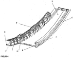
- FIG. 4 shows a three-dimensional view of a preferred embodiment of the column cover.
- the structure corresponds to the in FIG. 2 shown.
- the rejuvenation (3) is not visible because of the perspective.
- the raised, honeycomb-like surface structure (9) is arranged in the form of regular hexagons covering the surface of the window guide web (2).
- the increased surface structure (9) reinforces the window guide web (2), allows the reduction of the wall thickness of the window guide web (2).
- the reinforcing ribs (10) can be arranged both at regular and irregular intervals on the outside of the window guide web (2).
- the area of the end piece (6) is indicated on the left of the dashed line.
Landscapes
- Engineering & Computer Science (AREA)
- Mechanical Engineering (AREA)
- Manufacturing & Machinery (AREA)
- Chemical & Material Sciences (AREA)
- Combustion & Propulsion (AREA)
- Transportation (AREA)
- Injection Moulding Of Plastics Or The Like (AREA)
- Laminated Bodies (AREA)
- Vehicle Interior And Exterior Ornaments, Soundproofing, And Insulation (AREA)
- Compositions Of Macromolecular Compounds (AREA)
- Body Structure For Vehicles (AREA)
Description
- Die Erfindung betrifft eine Säulenabdeckung für Kraftfahrzeuge und deren Verwendung.
- Im Zuge immer strengerer Vorgaben zur Kohlendioxidemission von Kraftfahrzeugen gibt es starke Bestrebungen das Gewicht eines Fahrzeugs und damit dessen Treibstoffverbrauch zu senken. Stetige Weiterentwicklungen im Bereich der Kunststoffe ermöglichen den Ersatz von großen Teilen der Metallkarosserie durch entsprechend leichtere Elemente aus polymeren Werkstoffen. Insbesondere Teile oder auch der gesamte Fensterbereich können durch Elemente aus polymeren Werkstoffen ersetzt werden. Diese zeigen in vielen Fällen bei einem deutlich niedrigeren Gewicht eine vergleichbare Härte, Stabilität und Belastbarkeit wie bei einem Karosseriefenster aus Stahl. Zusätzlich wird auf Grund der Gewichtsreduzierung der Schwerpunkt des Fahrzeugs weiter nach unten verlagert, was einen positiven Einfluss auf das Fahrverhalten hat. Zudem können polymere Werkstoffe im Vergleich zu Metallen bei deutlich niedrigeren Temperaturen hergestellt, bearbeitet und verformt werden. Dies senkt den Energiebedarf und die Kosten bei der Herstellung der Werkstoffe.
- Formteile aus polymeren Werkstoffen können dabei in praktisch jeder gewünschten Form und Geometrie hergestellt werden. Spezielle Hochleistungskunststoffe wie Aramide, beispielsweise Kevlar weisen sehr hohe Festigkeiten und Stabilitäten auf.
- Viele Werkstoffteile aus Kunststoffen müssen verschiedenen Anforderungen und Funktionen gerecht werden. Wichtige Parameter sind hierbei die Stabilität, Bruchverhalten, Kratzfestigkeit, Schlagzähigkeit oder Kerbschlagzähigkeit. Neben technischen Gesichtspunkten wie Gewicht und Festigkeit der einzelnen Bauteile spielen auch die Form, Geometrie und das Aussehen eine zunehmend wichtigere Rolle. Vor allem in der Automobilindustrie sind neben mechanischen Eigenschaften auch Merkmale im Bereich des Designs und Ästhetik von großer Bedeutung.
- Um verschiedene Merkmale in polymeren Werkstoffen zu vereinen, werden diese aus unterschiedlich geformten und aus unterschiedlich beschaffenen Grundmaterialien zusammengesetzt. Etablierte Verfahren zur Herstellung dieser Werkstoffe umfassen zwei oder mehr Komponenten Spritzgussverfahren. Auf diese Art und Weise ist es möglich, Merkmale wie beispielsweise Witterungsbeständigkeit, Oberflächenglanz und Bruchbeständigkeit oder Torsionsstabilität mit einander zu vereinen. Zudem können die Anteile sehr teurer Werkstoffe reduziert werden.
-
DE 196 33 959 A1 offenbart einen Formkörper aus einem Träger und einem äußeren Zierfilm. Der äußere Film besitzt eine Zier- und eine Schutzschicht, wobei die Schutzschicht aus einer photopolymerisierbaren Harzzusammensetzung besteht. -
WO 2006/094484 A1 offenbart ein Verfahren zur Herstellung eines flächigen, zwei Komponenten enthaltenden Kunststoffkarosserieteils. In einer bevorzugten Ausführungsform sind die erste Komponente aus einem transparenten Polycarbonat und die zweite Komponente aus einem opaken Polycarbonat. -
DE 197 22 551 A1 offenbart ein Verfahren zur Herstellung von Kunststoffteilen im Zwei-Komponenten-Spritzgussverfahren. -
EP 1 695 808 A1 offenbart ein Zierteil für ein Kraftfahrzeug, beispielsweise eine Zierleiste. Das Zierteil umfasst ein Trägerteil aus einem thermoplastischen Kunststoff und ein Deckteil. Das Zierteil wird bevorzugt über einen Mehrkomponenten-Spritzgussprozess hergestellt. -
EP 2 272 718 A1 offenbart eine Säulenabdeckung nach dem Oberbegriff von Anspruch 1. - Aufgrund der unterschiedlichen Materialeigenschaften der einzelnen Polymere im Werkstück kommt es bei der Herstellung im Mehrkomponenten Spritzgussprozess zu Unterschieden im Abkühlverhalten. Unterschiede in der Wärmeabfuhr können so zu unterschiedlichen Schwindungsverhalten führen, das wiederum zu einem inhomogenen Erscheinungsbild am fertigen Werkstück führt. Insbesondere bei Werkstücken mit transparenten oder hochglänzenden Elementen führt dies leicht zu einer Störung der Reflexionsoptik und damit einem geringwertigen Aussehen vor allem im Kantenbereich.
- Die Erfindung hat die Aufgabe, ein Werkstück aus mindestens zwei unterschiedlichen Werkstoffen bereitzustellen, welches einen gleichmäßigen Kantenbereich bei gleichzeitig unterschiedlichen Materialschwindungsverhalten aufweist.
- Die Aufgabe der Erfindung wird durch eine Säulenabdeckung für Fahrzeuge gemäß Anspruch 1 gelöst. Bevorzugte Ausführungen gehen aus den Unteransprüchen hervor.
- Die erfindungsgemäße Verwendung der Säulenabdeckung für Fahrzeuge geht aus einem weiteren unabhängigen Anspruch hervor. Bevorzugte Ausführungen gehen aus den Unteransprüchen hervor.
- Die erfindungsgemäße Säulenabdeckung für Fahrzeuge umfasst mindestens ein polymeres Trägerteil mit einem integrierten Fensterführungssteg sowie einer Verjüngung zwischen dem polymeren Trägerteil und dem Fensterführungssteg. Der bevorzugt angespritzte Fensterführungssteg steht vom eigentlichen Trägerteil ab und die genaue Dimensionierung hängt von der Geometrie des passenden Werkstücks am Fahrzeug ab. Der Fensterführungssteg ist bevorzugt näherungsweise L-förmig ausgebildet und weist bevorzugt im abstehenden Bereich einen Winkel von 45° bis 135° zur Grundfläche des polymeren Trägerteils auf. Der Fensterführungssteg weist bevorzugt in beiden Teilstegen eine Länge von jeweils 10 mm bis 20 mm auf. Der Ausdruck "verjüngt" bedeutet im Sinne der Erfindung eine lineare oder graduelle Abnahme der Dicke des Fensterführungsstegs benachbart oder angrenzend zur Grundfläche des polymeren Trägerteils. Diese Abnahme der Dicke des integrierten Fensterführungsstegs gewährleistet eine verbesserte Reflexionsoptik auf der Sichtseite der Säulenabdeckung und erlaubt eine Gewichtsreduzierung der Säulenabdeckung und eine Ersparnis an polymerem Ausgangsmaterial. Der Fensterführungssteg ist bevorzugt aus demselben Werkstoff wie das polymere Trägerteil gefertigt und wird bevorzugt durch Formwerkzeuge mit entsprechenden Aussparungen im Spritzgussverfahren hergestellt.
- Das polymere Trägerteil sorgt für die Stabilität der Säulenabdeckung und beinhaltet polymere Materialien mit einer möglichst hohen Festigkeit, Kratzfestigkeit, Schlagzähigkeit oder Kerbschlagzähigkeit und geringerer Bruchneigung. Das polymere Trägerteil umfasst bevorzugt ein Montageelement. Das Montageelement ist bevorzugt F-förmig ausgebildet. Die genaue Formgebung des Montageelementes richtet sich dabei nach dem entsprechenden Gegenstück der Karosserie.
- Mit dem polymeren Trägerteil ist ein polymeres Deckteil über eine Kontaktfläche verbunden. Der Ausdruck "Kontaktfläche" beschreibt die Grenzfläche zwischen dem polymeren Trägerteil und dem polymeren Deckteil. Das polymere Deckteil kann sowohl dekorative Funktionen als auch Funktionen im Bereich der Werkzeugbeständigkeit übernehmen. Beispiele hierfür sind Oberflächen oder Beschichtungen welche die witterungs-, UV- oder chemische Beständigkeit der Säulenabdeckung erhöhen. Das polymere Trägerteil und das polymere Deckteil bilden mindestens ein gemeinsames abgerundetes Endstück. Der Ausdruck "Endstück" bezieht sich im Sinne der Erfindung bevorzugt auf einen endständigen Bereich in dem die Gesamtdicke aus polymerem Trägerteil und polymerem Deckteil oder deren Einzeldicken graduell oder linear abnehmen. Die Kontaktfläche zwischen polymerem Trägerteil und polymerem Deckteil verläuft innerhalb des Endstücks über eine Länge von mindestens 1 mm (gemessen vom Rand des Endstücks) in einem gemittelten Winkel von 5° bis 60° (Grad) zum polymeren Trägerteil hin oder von dem polymeren Trägerteil weg gerichtet (oberhalb oder unterhalb zur gemittelten Achse der Kontaktfläche zwischen dem polymeren Trägerteil und dem polymeren Deckteils außerhalb des/der Endstücks/e). Die Kontaktfläche kann linear oder gekrümmt verlaufen. Die Kontaktfläche verläuft innerhalb des Endstücks bevorzugt über eine Länge von 2 mm bis 20 mm in einem gemittelten Winkel von 10° bis 50°. Die Verschiebung der Kontaktfläche von der gemittelten Achse der Kontaktfläche zwischen dem polymeren Trägerteil und dem polymeren Deckteil (Horizontalen) bewirkt eine Ausdünnung des Anteils an polymerem Trägerteil oder polymerem Deckteil im Endstück. Diese Ausdünnung einer Materialkomponente vom polymeren Trägerteil oder polymeren Deckteil erlaubt eine Anpassung des Schwindungs- und Abkühlverhaltens im Endstück. Auf diese Art und Weise wird die Bildung von optischen Verzerrungen im Endstück verhindert. Bei langsamerer Abkühlung des polymeren Trägerteils kann die Masse von diesem im Bereich des Endstücks verringert werden und so ein insgesamt schnelleres Abkühlen bei geringerer Masse, bevorzugt gleichzeitig mit dem polymeren Deckteil ermöglichen.
- Je nach Geometrie der Säulenabdeckung können noch weitere gemeinsame, bevorzugt abgerundete, Endstücke vorhanden sein. Diese erfindungsgemäße Kantengeometrie kann umlaufend an allen gemeinsamen Kanten vom polymeren Trägerteil und polymeren Deckteil innerhalb der Säulenabdeckung oder nur an einzelnen Bauteilkanten ausgebildet sein.
- Die Verjüngung verjüngt sich bevorzugt von 1 mm bis 4 mm auf 0,2 mm bis 2 mm. Diese Abmessungen erlauben eine hohe Stabilität innerhalb der Verjüngung bei gleichzeitig minimalem Gewicht.
- Eine Versteifungsrippe ist bevorzugt innerhalb der Verjüngung, besonders bevorzugt sind mehrere Versteifungsrippen innerhalb der Verjüngung angebracht. Die Versteifungsrippen erhöhen deutlich die Stabilität und Bruchsicherheit des Fensterführungsstegs und sind innerhalb der Verjüngung besonders platzsparend angeordnet.
- Das polymere Trägerteil enthält bevorzugt Polyethylen (PE), Polycarbonate (PC), Polypropylen (PP), Polystyrol, Polybutadien, Polynitrile, Polyester, Polyurethane, Polymethylmethacrylate, Polyacrylate, Polyester, Polyamide, Polyethylenterephthalat (PET), bevorzugt Acrylnitril-Butadien-Styrol (ABS), Acrylester-Styrol-Acrylnitril (ASA), Acrylnitril-Butadien-Styrol - Polycarbonat (ABS+PC) und/oder Copolymere oder Gemische davon.
- Der Fensterführungssteg und/oder das Montageelement weisen bevorzugt an der Oberfläche eine Wandstärkenausdünnung auf 0,5 mm bis 3 mm auf, wobei die ausgedünnte Grundwand des Fensterführungsstegs und/oder das Montageelement bevorzugt durch eine wabenartige, kreisförmige oder poligonale erhöhte Oberflächenstruktur, besonders bevorzugt eine hexagonale erhöhte bienenwabenartige Oberflächenstruktur verstärkt werden. Die erhöhte Oberflächenstruktur gewährleistet auch bei Ausdünnung der Wandstärke die Stabilität und Bruchsicherheit des Fensterführungsstegs und/oder des Montageelements. Die Wandstärkenausdünnung verringert das Gewicht der Säulenabdeckung. Die erhöhte Struktur weist bevorzugt eine Dicke von 0,2 mm bis 1,5 mm auf. Die Gesamtdicke aus Fensterführungssteg und der erhöhten Oberflächenstruktur ist bevorzugt um den Faktor 1,2 bis 3 größer ist als die Dicke des darunterliegenden Fensterführungsstegs. Der genannte Faktor gewährleistet ein optimales Gewicht- zu Stabilitätsverhältnis des Fensterführungsstegs.
- Die erhöhte Oberflächenstruktur weist bevorzugt eine Schrägstellung von 1 ° bis 15 ° relativ zur Senkrechten auf der Oberfläche des Fensterführungsstegs und/oder das Montageelements unterhalb der Oberflächenstruktur auf. Diese Entformungsschräge verbessert das Herauslösen des bruchempfindlichen Fensterführungsstegs und/oder des Montageelements aus der Spritzgussform.
- Der Fensterführungssteg und/oder das Montageelement weisen in einer optionalen Ausgestaltungsform die erhöhte Oberflächenstruktur an Bereichen des Fensterführungsstegs und/oder des Montageelements ohne Wandstärkenausdünnung auf.
- Das polymere Deckteil enthält bevorzugt Polycarbonate (PC), Polymethylmethacrylat (PMMA), Styrol-Acrylnitril (SAN) und/oder Copolymere oder Gemische davon. Diese Polymere erlauben eine Verarbeitung zu hochglänzenden, teilweise glasähnlichen Oberflächen.
- Das polymere Trägerteil enthält bevorzugt anorganische oder organische Füllstoffe, besonders bevorzugt SiO2, Al2O3, TiO2, Tonmineralien, Silikate, Zeolithe, Glasfasern, Kohlenstofffasern, Glaskugeln, organische Fasern und/oder Gemische davon. Die Füllstoffe können die Stabilität des Trägerteils weiter erhöhen. Zudem können die Füllstoffe die Materialkosten senken oder gegebenenfalls die Feuerfestigkeit des polymeren Trägerteils erhöhen.
- Das Montageelement weist bevorzugt eine Dichtlippe auf. Die Dichtlippe ermöglicht einen flexiblen und abdichtenden Einbau der Säulenabdeckung im Fahrzeug.
- Das polymere Deckteil enthält bevorzugt einen Hardcoat, besonders bevorzugt thermisch- oder UV-härtende Lacke, besonders bevorzugt Polysiloxane, Polyacrylate, Polymethacrylate und/oder Gemische oder Copolymere davon. Der Hardcoat verbessert die Beständigkeit gegenüber mechanischen Kratzbeschädigungen, Witterungseinflüssen, UV-Strahlung und/oder aggressiven Chemikalien aus der Luft oder dem Bodenwasser. Zusätzlich kann der Hardcoat auch noch dekorative Funktionen wahrnehmen.
- Das polymere Deckteil weist bevorzugt eine mittlere optische Transparenz von mehr als 60 %, bevorzugt mehr als 80 % im Bereich von 400 nm bis 800 nm auf. Die hohe optische Transparenz verleiht dem polymeren Deckteil ein glasähnliches Aussehen bei nur geringem Eigengewicht.
- Die Versteifungsrippen weisen bevorzugt einen Abstand von 1 cm bis 15 cm, bevorzugt 2 cm bis 10 cm auf. Die so platzierten Versteifungsrippen erhöhen deutlich die Stabilität und Bruchsicherheit des Fensterführungsstegs.
- Der Fensterführungssteg und/oder das Montageelement weisen bevorzugt auf der der Verjüngung gegenüberliegende Seite Verstärkungsrippen auf, welche die Stabilität des Fensterführungsstegs und/oder des Montageelements weiter erhöhen. Die Säulenabdeckung enthält besonders bevorzugt Versteifungsrippen und Verstärkungsrippen.
- Die erfindungsgemäße Säulenabdeckung wird bevorzugt über ein Mehrkomponenten-Spritzgießverfahren oder ein Mehrkomponenten-Spritzprägeverfahren hergestellt.
- Die Erfindung umfasst des Weiteren die Verwendung der Säulenabdeckung in Fahrzeugen, bevorzugt Kraftfahrzeugen, Lastkraftwagen, Bussen, besonders bevorzugt als Zierleiste in Kraftfahrzeugen.
- Im Folgenden wird die Erfindung anhand von Zeichnungen näher erläutert. Die Zeichnungen sind rein schematische Darstellungen und nicht maßstabsgetreu. Sie schränken die Erfindung in keiner Weise ein.
- Es zeigen:
-
Figur 1 einen Querschnitt einer Säulenabdeckung nach dem Stand der Technik, -
Figur 2 einen Querschnitt einer erfindungsgemäßen Säulenabdeckung, -
Figur 3a einen vergrößerten Querschnitt der Kontaktfläche zwischen dem polymeren Trägerteil und dem polymeren Deckteil, -
Figur 3b einen vergrößerten Querschnitt der Kontaktfläche zwischen dem polymeren Trägerteil und dem polymeren Deckteil und -
Figur 4 eine dreidimensionale Ansicht einer bevorzugten Ausführungsform der Säulenabdeckung. -
Figur 1 zeigt einen Querschnitt einer Säulenabdeckung nach dem Stand der Technik. Ein polymeres Trägerteil (1) mit einem angespritzten Fensterführungssteg (2) und einem F-förmigen Montageelement (7) mit einer Dichtlippe (8) ist von einem polymeren Deckteil (4) umgeben. Der Fensterführungssteg (2) ist über eine Verjüngung (3) mit dem polymeren Trägerteil (1) verbunden. Der Bereich des abgerundeten Endstücks (6) (links der gestrichelten Linie) geht fließend entlang der Kontaktfläche (11) in das polymere Trägerteil (1) und das polymere Deckteil (4) über. Das polymere Deckteil (4) umschließt im abgerundeten Endstück (6) das polymere Trägerteil (1). Aufgrund unterschiedlicher Materialien des polymeren Deckteils (4) und des polymeren Trägerteils (1) kann es beim Abkühlen nach einem 2-Komponentenspritzgussprozess zu optischen Verzerrungen und zu einer unregelmäßigen Phasengrenze an der Kontaktfläche (11) kommen. -
Figur 2 zeigt einen Querschnitt einer erfindungsgemäßen Säulenabdeckung. Der Grundaufbau aus polymerem Trägerteil (1) mit Fensterführungssteg (2), F-förmigem Montageelement (7) mit einer Dichtlippe (8) und polymerem Deckteil (4) entspricht dem inFigur 1 gezeigten. Eine Versteifungsrippe (5) ist innerhalb der Verjüngung (3) angeordnet und erlaubt eine wirksame Stabilisierung des Fensterführungsstegs (2) ohne zusätzlichen Platzbedarf. Der Fensterführungssteg (2) nimmt innerhalb der Verjüngung (3) vom größeren Ausgangsdurchmesser (b) auf den kleineren Durchmesser (a) ab. Der Fensterführungssteg (2) weist eine Wandstärkenausdünnung (13) auf eine Dicke von 0,5 mm bis 3 mm und eine erhöhte Struktur (9) auf. Im Bereich des abgerundeten Endstücks (6) (links der vertikalen gestrichelten Linie) läuft die Kontaktfläche (11) zwischen dem polymeren Trägerteil (1) und dem polymeren Deckteil (4) oberhalb der über den horizontalen Bereich der Kontaktfläche (11) gemittelten Achse (12) (horizontale gestrichelte Linie) in einem Winkel von 5° bis 60°. -
Figur 3a zeigt einen vergrößerten Querschnitt der Kontaktfläche (11) zwischen dem polymeren Trägerteil (1) und dem polymeren Deckteil (4). Innerhalb des Endstücks (6) verläuft die Kontaktfläche (11) über eine Länge (15) von mindestens 1 mm in einem Winkel α (Alfa) von 5° bis 60° zwischen der horizontal gemittelten Achse (12) entlang der Kontaktfläche (11) außerhalb des Endstücks (6) und der gemittelten Achse (14) zwischen dem polymeren Trägerteil (1) und dem polymeren Deckteil (4) innerhalb des Endstücks (6). -
Figur 3b zeigt einen weiteren vergrößerten Querschnitt der Kontaktfläche (11) zwischen dem polymeren Trägerteil (1) und dem polymeren Deckteil (4). Innerhalb des Endstücks (6) verläuft die Kontaktfläche (11) über eine Länge (15) von mindestens 1 mm in einem Winkel α (Alfa) von 5° bis 60° zwischen der horizontal gemittelten Achse (12) entlang der Kontaktfläche (11) außerhalb des Endstücks (6) und der gemittelten Achse (14) zwischen dem polymeren Trägerteil (1) und dem polymeren Deckteil (4) innerhalb des Endstücks (6). Die Kontaktfläche (11) verläuft in diesem Beispiel entlang der Länge (15) über eine gekrümmte Strecke. Die Achse (14) wird bevorzugt als einfache lineare Regressionsgerade entlang der Länge (15) ermittelt. -
Figur 4 zeigt eine dreidimensionale Ansicht einer bevorzugten Ausführungsform der Säulenabdeckung. Der Aufbau entspricht dem inFigur 2 gezeigten. Die Verjüngung (3) ist aufgrund der Perspektive nicht zu sehen. Die erhöhte, bienenwabenartige Oberflächenstruktur (9) ist in Form von regelmäßigen Sechsecken flächendeckend auf der Oberfläche des Fensterführungsstegs (2) angeordnet. Die erhöhte Oberflächenstruktur (9) verstärkt den Fensterführungssteg (2), erlaubt die Reduzierung der Wandstärke des Fensterführungsstegs (2). Die Verstärkungsrippen (10) können sowohl in regelmäßigem als auch unregelmäßigem Abstand an der Außenseite des Fensterführungsstegs (2) angeordnet werden. Der Bereich des Endstücks (6) ist links der gestrichelten Linie angedeutet. -
- (1)
- polymeres Trägerteil
- (2)
- Fensterführungssteg
- (3)
- Verjüngung
- (4)
- polymeres Deckteil
- (5)
- Versteifungsrippe
- (6)
- Endstück
- (7)
- Montageelement
- (8)
- Dichtlippe
- (9)
- erhöhte Struktur
- (10)
- Verstärkungsrippen
- (11)
- Kontaktfläche
- (12)
- Kontaktflächenachse / horizontal über das Bauteil gemittelte Achse (ohne vertikale Anspritzungen)
- (13)
- Wandstärkenausdünnung
- (14)
- gemittelte Achse zwischen dem polymeren Trägerteil (1) und dem polymeren Deckteil (4) innerhalb des Endstücks (6)
- (15)
- Länge der gewinkelten Kontaktfläche innerhalb des Endstücks
- (a)
- minimale Abmessung der Verjüngung
- (b)
- maximale Abmessung der Verjüngung
- (α)
- Winkel (Alfa) im Endstück zwischen der Kontaktfläche und der horizontal gemittelten Kontaktfläche
Claims (15)
- Säulenabdeckung für Fahrzeuge mindestens umfassend:a. ein Trägerteil (1) mit einem integrierten Fensterführungssteg (2) und einem Montageelement (7),b. eine Verjüngung (3) an der Berührungsstelle des Fensterführungsstegs (2) zum Trägerteil (1),c. ein mit dem Trägerteil (1) über eine Kontaktfläche (11) verbundenes polymeres Deckteil (4), wobei,das Trägerteil (1) und das Deckteil (4) mindestens ein gemeinsames Endstück (6) bilden, dadurch gekennzeichnet dass die Kontaktfläche (11) innerhalb des Endstücks (6) über eine Länge (15) von mindestens 1 mm in einem gemittelten Winkel α von 5° bis 60° oberhalb oder unterhalb zu einer gemittelten Achse (12) entlang der Kontaktfläche (11) außerhalb des Endstücks (6) verläuft.
- Säulenabdeckung nach Anspruch 1, wobei die Verjüngung (3) sich von 1 mm bis 4 mm auf 0,2 mm bis 2 mm verjüngt.
- Säulenabdeckung nach Anspruch 1 oder 2, wobei eine Versteifungsrippe (5) innerhalb der Verjüngung (3), bevorzugt mehrere Versteifungsrippen (5) innerhalb der Verjüngung (3) angebracht sind.
- Säulenabdeckung nach einem der Ansprüche 1 bis 3, wobei das Trägerteil (1) Polyethylen (PE), Polycarbonate (PC), Polypropylen (PP), Polystyrol, Polybutadien, Polynitrile, Polyester, Polyurethane, Polymethylmetacrylate, Polyacrylate, Polyamide, Polyethylenterephthalat (PET), Polybutylenterephthalat (PBT), bevorzugt Acrylnitril-Butadien-Styrol (ABS), Acrylester-Styrol-Acrylnitril (ASA), Acrylnitril-Butadien-Styrol - Polycarbonat (ABS/PC), PET/PC, PBT/PC und/oder Copolymere oder Gemische davon enthält.
- Säulenabdeckung nach einem der Ansprüche 1 bis 4, wobei der Fensterführungssteg (2) und/oder das Montageelement (7) eine Wandstärkenausdünnung (13) auf eine Dicke von 0,5 mm bis 3 mm aufweist.
- Säulenabdeckung nach einem der Ansprüche 1 bis 5, wobei der Fensterführungssteg (2) und/oder das Montageelement (7) eine erhöhte Oberflächenstruktur (9), bevorzugt eine wabenartige kreisförmige oder poligonale erhöhte Oberflächenstruktur (9), besonders bevorzugt eine hexagonale erhöhte Oberflächenstruktur (9) aufweist.
- Säulenabdeckung nach Anspruch 6, wobei die erhöhte Oberflächenstruktur (9) auf der Wandstärkenausdünnung (13) angeordnet ist,
- Säulenabdeckung nach einem der Ansprüche 1 bis 7, wobei das Deckteil (4) Polycarbonate (PC), Polymethylmethacrylat (PMMA), Styrol-Acrylnitril (SAN) und/oder Copolymere oder Gemische davon enthält.
- Säulenabdeckung nach einem der Ansprüche 1 bis 8, wobei das Montageelement (7) F-förmig ausgebildet ist.
- Säulenabdeckung nach einem der Ansprüche 1 bis 9, wobei das Trägerteil (1) anorganische oder organische Füllstoffe, bevorzugt SiO2, Al2O3, TiO2, Tonmineralien, Silikate, Zeolithe, Glasfasern, Kohlenstofffasern, Glaskugeln, organische Fasern und/oder Gemische davon enthält.
- Säulenabdeckung nach einem der Ansprüche 1 bis 10, wobei das Montageelement (7) eine Dichtlippe (8) aufweist.
- Säulenabdeckung nach einem der Ansprüche 1 bis 11, wobei das Deckteil (4) einen Hardcoat, bevorzugt thermisch- oder UV-härtende Lacke, besonders bevorzugt Polysiloxane, Polyacrylate, Polymethacrylate und/oder Gemische oder Copolymere davon enthält.
- Säulenabdeckung nach einem der Ansprüche 1 bis 12, wobei die Versteifungsrippen (5) einen Abstand von 1 cm bis 15 cm, bevorzugt von 2 cm bis 10 cm aufweisen.
- Säulenabdeckung nach einem der Ansprüche 1 bis 13, wobei der Fensterführungssteg (2) und/oder das Montageelement (7) Verstärkungsrippen (10) aufweisen.
- Verwendung der Säulenabdeckung nach einem der Ansprüche 1 bis 14 in Fahrzeugen, bevorzugt Kraftfahrzeugen, Lastkraftwagen, Bussen, besonders bevorzugt als Zierleiste in Kraftfahrzeugen.
Priority Applications (1)
| Application Number | Priority Date | Filing Date | Title |
|---|---|---|---|
| EP12753507.8A EP2758276B1 (de) | 2011-09-23 | 2012-09-04 | Säulenabdeckung für kraftfahrzeuge |
Applications Claiming Priority (3)
| Application Number | Priority Date | Filing Date | Title |
|---|---|---|---|
| EP11182550 | 2011-09-23 | ||
| EP12753507.8A EP2758276B1 (de) | 2011-09-23 | 2012-09-04 | Säulenabdeckung für kraftfahrzeuge |
| PCT/EP2012/067196 WO2013041367A1 (de) | 2011-09-23 | 2012-09-04 | Säulenabdeckung für kraftfahrzeuge |
Publications (2)
| Publication Number | Publication Date |
|---|---|
| EP2758276A1 EP2758276A1 (de) | 2014-07-30 |
| EP2758276B1 true EP2758276B1 (de) | 2016-05-11 |
Family
ID=46763113
Family Applications (1)
| Application Number | Title | Priority Date | Filing Date |
|---|---|---|---|
| EP12753507.8A Active EP2758276B1 (de) | 2011-09-23 | 2012-09-04 | Säulenabdeckung für kraftfahrzeuge |
Country Status (9)
| Country | Link |
|---|---|
| US (1) | US9085326B2 (de) |
| EP (1) | EP2758276B1 (de) |
| JP (1) | JP5866020B2 (de) |
| KR (1) | KR101643060B1 (de) |
| CN (1) | CN203996015U (de) |
| ES (1) | ES2586772T3 (de) |
| PL (1) | PL2758276T3 (de) |
| PT (1) | PT2758276T (de) |
| WO (1) | WO2013041367A1 (de) |
Families Citing this family (4)
| Publication number | Priority date | Publication date | Assignee | Title |
|---|---|---|---|---|
| SE1250876A1 (sv) * | 2012-07-18 | 2014-01-19 | Scania Cv Ab | Panelparti |
| JP6494241B2 (ja) * | 2014-10-28 | 2019-04-03 | 株式会社小糸製作所 | 二色成形品 |
| RU2017127971A (ru) * | 2015-03-09 | 2019-02-04 | Кхи Иль КИМ | Дверная стойка для транспортного средства и способ ее изготовления |
| JP6579705B2 (ja) | 2015-09-29 | 2019-09-25 | クミ化成株式会社 | 構造体及びその製造方法 |
Family Cites Families (16)
| Publication number | Priority date | Publication date | Assignee | Title |
|---|---|---|---|---|
| JPS6472821A (en) | 1987-09-14 | 1989-03-17 | Yazaki Corp | Platelike injection melded object |
| JPH04353415A (ja) * | 1991-05-31 | 1992-12-08 | Toyoda Gosei Co Ltd | 透明樹脂製品の製造方法 |
| DE4219344C2 (de) | 1991-06-14 | 1997-05-07 | Toyoda Gosei Kk | Langes Sandwich-Formteil |
| JP2531417B2 (ja) * | 1991-06-14 | 1996-09-04 | 豊田合成株式会社 | サイドモ―ル |
| US5571581A (en) | 1991-06-14 | 1996-11-05 | Toyoda Gosei Co., Ltd. | Long sandwich molded article |
| US6103168A (en) * | 1995-03-22 | 2000-08-15 | Gencorp Inc. | Method for manufacturing an integrally molded applique article for a vehicle with integral cosmetic and functional material |
| JP3479757B2 (ja) | 1995-08-25 | 2003-12-15 | 豊田合成株式会社 | 熱可塑性樹脂成形品の加飾成形方法 |
| DE19722551A1 (de) | 1997-05-28 | 1998-12-03 | Hohe Gmbh & Co Kg | Verfahren zur Herstellung von Kunststoffteilen in einem Zwei-Komponenten-Spritzgußprozeß |
| DE20201528U1 (de) * | 2002-02-01 | 2003-06-26 | WKW Kunststofftechnik AG, Rüthi | Säulenblende für die Säulenverkleidung an einem Fahrzeug |
| JP2003320904A (ja) * | 2002-04-26 | 2003-11-11 | Hashimoto Forming Ind Co Ltd | 自動車用ピラーフィニッシャー |
| DE202004006873U1 (de) | 2004-04-29 | 2004-07-29 | Wkw Kunststofftechnik Ag | Säulenblende mit Versteifungstasche für die Säulen-Verkleidung an einem Fahrzeug |
| DE102005036771A1 (de) * | 2005-02-24 | 2006-09-07 | Dura Automotive Plettenberg Entwicklungs- Und Vertriebs Gmbh | Zierteil für ein Kraftfahrzeug |
| DE102005010624A1 (de) | 2005-03-08 | 2006-09-14 | Webasto Ag | Verfahren zum Herstellen eines zwei Komponenten aufweisenden Kunststoffkarosserieteils für ein Fahrzeug |
| DE102007024149B4 (de) * | 2007-05-24 | 2012-04-19 | Bayerische Motoren Werke Ag | Kraftfahrzeug |
| JP4940044B2 (ja) * | 2007-07-26 | 2012-05-30 | 本田技研工業株式会社 | 車両の樹脂製外装部品 |
| DE102009026070B4 (de) | 2009-06-29 | 2018-08-16 | Dura Automotive Holdings U.K., Ltd. | Säulenblende mit integrierter Fixierhilfe |
-
2012
- 2012-09-04 PL PL12753507.8T patent/PL2758276T3/pl unknown
- 2012-09-04 CN CN201290000351.7U patent/CN203996015U/zh not_active Expired - Fee Related
- 2012-09-04 PT PT127535078T patent/PT2758276T/pt unknown
- 2012-09-04 KR KR1020147007261A patent/KR101643060B1/ko not_active Expired - Fee Related
- 2012-09-04 US US14/344,571 patent/US9085326B2/en not_active Expired - Fee Related
- 2012-09-04 WO PCT/EP2012/067196 patent/WO2013041367A1/de not_active Ceased
- 2012-09-04 JP JP2014531162A patent/JP5866020B2/ja not_active Expired - Fee Related
- 2012-09-04 ES ES12753507.8T patent/ES2586772T3/es active Active
- 2012-09-04 EP EP12753507.8A patent/EP2758276B1/de active Active
Also Published As
| Publication number | Publication date |
|---|---|
| JP5866020B2 (ja) | 2016-02-17 |
| US20140252804A1 (en) | 2014-09-11 |
| EP2758276A1 (de) | 2014-07-30 |
| JP2014527932A (ja) | 2014-10-23 |
| CN203996015U (zh) | 2014-12-10 |
| KR101643060B1 (ko) | 2016-08-10 |
| US9085326B2 (en) | 2015-07-21 |
| KR20140051439A (ko) | 2014-04-30 |
| ES2586772T3 (es) | 2016-10-18 |
| PT2758276T (pt) | 2016-08-17 |
| WO2013041367A1 (de) | 2013-03-28 |
| PL2758276T3 (pl) | 2016-11-30 |
Similar Documents
| Publication | Publication Date | Title |
|---|---|---|
| EP2758277B1 (de) | Säulenabdeckung für kraftfahrzeuge | |
| EP2632750B1 (de) | Fugenlose heckklappe | |
| EP2909050B1 (de) | Polymere fahrzeugscheibe mit led-anordnung | |
| EP2763833B1 (de) | Verfahren zur herstellung eines kunststoff-zierteils | |
| EP3169502B1 (de) | Verfahren zur herstellung eines kunststoff-fahrzeuganbauteils | |
| EP3191297B1 (de) | Blende für kraftfahrzeugverscheibungssysteme | |
| EP2758276A1 (de) | Säulenabdeckung für kraftfahrzeuge | |
| EP2758278B1 (de) | Säulenabdeckung für kraftfahrzeuge | |
| EP3233551A1 (de) | Polymere scheibe mit anextrudiertem dichtungsprofil | |
| EP2455259B1 (de) | Verkleidung einer Außenrückblickspiegelanordnung | |
| WO2018172194A1 (de) | Verfahren zur herstellung eines kunststoff-fahrzeuganbauteils | |
| EP2790842B1 (de) | Polymeres werkstück zur flutbeschichtung | |
| DE102011056016A1 (de) | Verkleidungsblende | |
| EP2580077B2 (de) | Fahrzeugfenster mit integriertem rollo | |
| EP3519217B1 (de) | Kraftfahrzeug, aufweisend zwei a-säulen und eine frontscheibe | |
| WO2017186479A1 (de) | Polymere seitenscheibe mit integriertem lüftungsschacht |
Legal Events
| Date | Code | Title | Description |
|---|---|---|---|
| PUAI | Public reference made under article 153(3) epc to a published international application that has entered the european phase |
Free format text: ORIGINAL CODE: 0009012 |
|
| 17P | Request for examination filed |
Effective date: 20140221 |
|
| AK | Designated contracting states |
Kind code of ref document: A1 Designated state(s): AL AT BE BG CH CY CZ DE DK EE ES FI FR GB GR HR HU IE IS IT LI LT LU LV MC MK MT NL NO PL PT RO RS SE SI SK SM TR |
|
| DAX | Request for extension of the european patent (deleted) | ||
| GRAP | Despatch of communication of intention to grant a patent |
Free format text: ORIGINAL CODE: EPIDOSNIGR1 |
|
| INTG | Intention to grant announced |
Effective date: 20151116 |
|
| GRAS | Grant fee paid |
Free format text: ORIGINAL CODE: EPIDOSNIGR3 |
|
| GRAA | (expected) grant |
Free format text: ORIGINAL CODE: 0009210 |
|
| AK | Designated contracting states |
Kind code of ref document: B1 Designated state(s): AL AT BE BG CH CY CZ DE DK EE ES FI FR GB GR HR HU IE IS IT LI LT LU LV MC MK MT NL NO PL PT RO RS SE SI SK SM TR |
|
| REG | Reference to a national code |
Ref country code: GB Ref legal event code: FG4D Free format text: NOT ENGLISH |
|
| REG | Reference to a national code |
Ref country code: CH Ref legal event code: EP |
|
| REG | Reference to a national code |
Ref country code: AT Ref legal event code: REF Ref document number: 798376 Country of ref document: AT Kind code of ref document: T Effective date: 20160515 |
|
| REG | Reference to a national code |
Ref country code: IE Ref legal event code: FG4D Free format text: LANGUAGE OF EP DOCUMENT: GERMAN |
|
| REG | Reference to a national code |
Ref country code: DE Ref legal event code: R096 Ref document number: 502012007076 Country of ref document: DE |
|
| REG | Reference to a national code |
Ref country code: RO Ref legal event code: EPE |
|
| REG | Reference to a national code |
Ref country code: FR Ref legal event code: PLFP Year of fee payment: 5 |
|
| REG | Reference to a national code |
Ref country code: PT Ref legal event code: SC4A Ref document number: 2758276 Country of ref document: PT Date of ref document: 20160817 Kind code of ref document: T Free format text: AVAILABILITY OF NATIONAL TRANSLATION Effective date: 20160803 Ref country code: NL Ref legal event code: FP |
|
| REG | Reference to a national code |
Ref country code: SE Ref legal event code: TRGR |
|
| REG | Reference to a national code |
Ref country code: LT Ref legal event code: MG4D |
|
| REG | Reference to a national code |
Ref country code: ES Ref legal event code: FG2A Ref document number: 2586772 Country of ref document: ES Kind code of ref document: T3 Effective date: 20161018 |
|
| PG25 | Lapsed in a contracting state [announced via postgrant information from national office to epo] |
Ref country code: NO Free format text: LAPSE BECAUSE OF FAILURE TO SUBMIT A TRANSLATION OF THE DESCRIPTION OR TO PAY THE FEE WITHIN THE PRESCRIBED TIME-LIMIT Effective date: 20160811 Ref country code: FI Free format text: LAPSE BECAUSE OF FAILURE TO SUBMIT A TRANSLATION OF THE DESCRIPTION OR TO PAY THE FEE WITHIN THE PRESCRIBED TIME-LIMIT Effective date: 20160511 Ref country code: LT Free format text: LAPSE BECAUSE OF FAILURE TO SUBMIT A TRANSLATION OF THE DESCRIPTION OR TO PAY THE FEE WITHIN THE PRESCRIBED TIME-LIMIT Effective date: 20160511 |
|
| PG25 | Lapsed in a contracting state [announced via postgrant information from national office to epo] |
Ref country code: LV Free format text: LAPSE BECAUSE OF FAILURE TO SUBMIT A TRANSLATION OF THE DESCRIPTION OR TO PAY THE FEE WITHIN THE PRESCRIBED TIME-LIMIT Effective date: 20160511 Ref country code: HR Free format text: LAPSE BECAUSE OF FAILURE TO SUBMIT A TRANSLATION OF THE DESCRIPTION OR TO PAY THE FEE WITHIN THE PRESCRIBED TIME-LIMIT Effective date: 20160511 Ref country code: GR Free format text: LAPSE BECAUSE OF FAILURE TO SUBMIT A TRANSLATION OF THE DESCRIPTION OR TO PAY THE FEE WITHIN THE PRESCRIBED TIME-LIMIT Effective date: 20160812 Ref country code: RS Free format text: LAPSE BECAUSE OF FAILURE TO SUBMIT A TRANSLATION OF THE DESCRIPTION OR TO PAY THE FEE WITHIN THE PRESCRIBED TIME-LIMIT Effective date: 20160511 |
|
| PG25 | Lapsed in a contracting state [announced via postgrant information from national office to epo] |
Ref country code: EE Free format text: LAPSE BECAUSE OF FAILURE TO SUBMIT A TRANSLATION OF THE DESCRIPTION OR TO PAY THE FEE WITHIN THE PRESCRIBED TIME-LIMIT Effective date: 20160511 Ref country code: DK Free format text: LAPSE BECAUSE OF FAILURE TO SUBMIT A TRANSLATION OF THE DESCRIPTION OR TO PAY THE FEE WITHIN THE PRESCRIBED TIME-LIMIT Effective date: 20160511 |
|
| REG | Reference to a national code |
Ref country code: DE Ref legal event code: R097 Ref document number: 502012007076 Country of ref document: DE |
|
| PG25 | Lapsed in a contracting state [announced via postgrant information from national office to epo] |
Ref country code: SM Free format text: LAPSE BECAUSE OF FAILURE TO SUBMIT A TRANSLATION OF THE DESCRIPTION OR TO PAY THE FEE WITHIN THE PRESCRIBED TIME-LIMIT Effective date: 20160511 |
|
| PLBE | No opposition filed within time limit |
Free format text: ORIGINAL CODE: 0009261 |
|
| STAA | Information on the status of an ep patent application or granted ep patent |
Free format text: STATUS: NO OPPOSITION FILED WITHIN TIME LIMIT |
|
| 26N | No opposition filed |
Effective date: 20170214 |
|
| PG25 | Lapsed in a contracting state [announced via postgrant information from national office to epo] |
Ref country code: MC Free format text: LAPSE BECAUSE OF FAILURE TO SUBMIT A TRANSLATION OF THE DESCRIPTION OR TO PAY THE FEE WITHIN THE PRESCRIBED TIME-LIMIT Effective date: 20160511 |
|
| REG | Reference to a national code |
Ref country code: CH Ref legal event code: PL |
|
| PG25 | Lapsed in a contracting state [announced via postgrant information from national office to epo] |
Ref country code: SI Free format text: LAPSE BECAUSE OF FAILURE TO SUBMIT A TRANSLATION OF THE DESCRIPTION OR TO PAY THE FEE WITHIN THE PRESCRIBED TIME-LIMIT Effective date: 20160511 |
|
| REG | Reference to a national code |
Ref country code: IE Ref legal event code: MM4A |
|
| PG25 | Lapsed in a contracting state [announced via postgrant information from national office to epo] |
Ref country code: LI Free format text: LAPSE BECAUSE OF NON-PAYMENT OF DUE FEES Effective date: 20160930 Ref country code: CH Free format text: LAPSE BECAUSE OF NON-PAYMENT OF DUE FEES Effective date: 20160930 Ref country code: IE Free format text: LAPSE BECAUSE OF NON-PAYMENT OF DUE FEES Effective date: 20160904 |
|
| REG | Reference to a national code |
Ref country code: FR Ref legal event code: PLFP Year of fee payment: 6 |
|
| PG25 | Lapsed in a contracting state [announced via postgrant information from national office to epo] |
Ref country code: HU Free format text: LAPSE BECAUSE OF FAILURE TO SUBMIT A TRANSLATION OF THE DESCRIPTION OR TO PAY THE FEE WITHIN THE PRESCRIBED TIME-LIMIT; INVALID AB INITIO Effective date: 20120904 |
|
| PG25 | Lapsed in a contracting state [announced via postgrant information from national office to epo] |
Ref country code: CY Free format text: LAPSE BECAUSE OF FAILURE TO SUBMIT A TRANSLATION OF THE DESCRIPTION OR TO PAY THE FEE WITHIN THE PRESCRIBED TIME-LIMIT Effective date: 20160511 Ref country code: MK Free format text: LAPSE BECAUSE OF FAILURE TO SUBMIT A TRANSLATION OF THE DESCRIPTION OR TO PAY THE FEE WITHIN THE PRESCRIBED TIME-LIMIT Effective date: 20160511 Ref country code: MT Free format text: LAPSE BECAUSE OF FAILURE TO SUBMIT A TRANSLATION OF THE DESCRIPTION OR TO PAY THE FEE WITHIN THE PRESCRIBED TIME-LIMIT Effective date: 20160511 Ref country code: IS Free format text: LAPSE BECAUSE OF FAILURE TO SUBMIT A TRANSLATION OF THE DESCRIPTION OR TO PAY THE FEE WITHIN THE PRESCRIBED TIME-LIMIT Effective date: 20160511 |
|
| PG25 | Lapsed in a contracting state [announced via postgrant information from national office to epo] |
Ref country code: BG Free format text: LAPSE BECAUSE OF FAILURE TO SUBMIT A TRANSLATION OF THE DESCRIPTION OR TO PAY THE FEE WITHIN THE PRESCRIBED TIME-LIMIT Effective date: 20160511 |
|
| REG | Reference to a national code |
Ref country code: FR Ref legal event code: PLFP Year of fee payment: 7 |
|
| PG25 | Lapsed in a contracting state [announced via postgrant information from national office to epo] |
Ref country code: AL Free format text: LAPSE BECAUSE OF FAILURE TO SUBMIT A TRANSLATION OF THE DESCRIPTION OR TO PAY THE FEE WITHIN THE PRESCRIBED TIME-LIMIT Effective date: 20160511 |
|
| REG | Reference to a national code |
Ref country code: AT Ref legal event code: MM01 Ref document number: 798376 Country of ref document: AT Kind code of ref document: T Effective date: 20170904 |
|
| PG25 | Lapsed in a contracting state [announced via postgrant information from national office to epo] |
Ref country code: AT Free format text: LAPSE BECAUSE OF NON-PAYMENT OF DUE FEES Effective date: 20170904 |
|
| PGFP | Annual fee paid to national office [announced via postgrant information from national office to epo] |
Ref country code: LU Payment date: 20210824 Year of fee payment: 10 Ref country code: NL Payment date: 20210813 Year of fee payment: 10 |
|
| PGFP | Annual fee paid to national office [announced via postgrant information from national office to epo] |
Ref country code: CZ Payment date: 20210818 Year of fee payment: 10 Ref country code: IT Payment date: 20210811 Year of fee payment: 10 |
|
| PGFP | Annual fee paid to national office [announced via postgrant information from national office to epo] |
Ref country code: BE Payment date: 20210817 Year of fee payment: 10 Ref country code: TR Payment date: 20210902 Year of fee payment: 10 Ref country code: SE Payment date: 20210910 Year of fee payment: 10 Ref country code: SK Payment date: 20210813 Year of fee payment: 10 Ref country code: RO Payment date: 20210831 Year of fee payment: 10 Ref country code: PL Payment date: 20210812 Year of fee payment: 10 |
|
| PGFP | Annual fee paid to national office [announced via postgrant information from national office to epo] |
Ref country code: PT Payment date: 20210903 Year of fee payment: 10 |
|
| PGFP | Annual fee paid to national office [announced via postgrant information from national office to epo] |
Ref country code: ES Payment date: 20211005 Year of fee payment: 10 |
|
| REG | Reference to a national code |
Ref country code: SK Ref legal event code: MM4A Ref document number: E 21805 Country of ref document: SK Effective date: 20220904 |
|
| PG25 | Lapsed in a contracting state [announced via postgrant information from national office to epo] |
Ref country code: RO Free format text: LAPSE BECAUSE OF NON-PAYMENT OF DUE FEES Effective date: 20220904 Ref country code: PT Free format text: LAPSE BECAUSE OF NON-PAYMENT OF DUE FEES Effective date: 20230306 Ref country code: CZ Free format text: LAPSE BECAUSE OF NON-PAYMENT OF DUE FEES Effective date: 20220904 |
|
| REG | Reference to a national code |
Ref country code: SE Ref legal event code: EUG |
|
| REG | Reference to a national code |
Ref country code: NL Ref legal event code: MM Effective date: 20221001 |
|
| REG | Reference to a national code |
Ref country code: BE Ref legal event code: MM Effective date: 20220930 |
|
| PG25 | Lapsed in a contracting state [announced via postgrant information from national office to epo] |
Ref country code: NL Free format text: LAPSE BECAUSE OF NON-PAYMENT OF DUE FEES Effective date: 20221001 Ref country code: LU Free format text: LAPSE BECAUSE OF NON-PAYMENT OF DUE FEES Effective date: 20220904 |
|
| PG25 | Lapsed in a contracting state [announced via postgrant information from national office to epo] |
Ref country code: SK Free format text: LAPSE BECAUSE OF NON-PAYMENT OF DUE FEES Effective date: 20220904 Ref country code: SE Free format text: LAPSE BECAUSE OF NON-PAYMENT OF DUE FEES Effective date: 20220905 |
|
| PG25 | Lapsed in a contracting state [announced via postgrant information from national office to epo] |
Ref country code: BE Free format text: LAPSE BECAUSE OF NON-PAYMENT OF DUE FEES Effective date: 20220930 |
|
| REG | Reference to a national code |
Ref country code: ES Ref legal event code: FD2A Effective date: 20231026 |
|
| PG25 | Lapsed in a contracting state [announced via postgrant information from national office to epo] |
Ref country code: IT Free format text: LAPSE BECAUSE OF NON-PAYMENT OF DUE FEES Effective date: 20220904 |
|
| PG25 | Lapsed in a contracting state [announced via postgrant information from national office to epo] |
Ref country code: PL Free format text: LAPSE BECAUSE OF NON-PAYMENT OF DUE FEES Effective date: 20220904 |
|
| PG25 | Lapsed in a contracting state [announced via postgrant information from national office to epo] |
Ref country code: ES Free format text: LAPSE BECAUSE OF NON-PAYMENT OF DUE FEES Effective date: 20220905 |
|
| PG25 | Lapsed in a contracting state [announced via postgrant information from national office to epo] |
Ref country code: ES Free format text: LAPSE BECAUSE OF NON-PAYMENT OF DUE FEES Effective date: 20220905 |
|
| PGFP | Annual fee paid to national office [announced via postgrant information from national office to epo] |
Ref country code: DE Payment date: 20240730 Year of fee payment: 13 |
|
| PGFP | Annual fee paid to national office [announced via postgrant information from national office to epo] |
Ref country code: GB Payment date: 20240801 Year of fee payment: 13 |
|
| PGFP | Annual fee paid to national office [announced via postgrant information from national office to epo] |
Ref country code: FR Payment date: 20240808 Year of fee payment: 13 |