EP2754789B1 - Schließblech oder -leiste und Verfahren zur Herstellung eines derartigen Schließblechs oder einer derartigen Schließleiste - Google Patents
Schließblech oder -leiste und Verfahren zur Herstellung eines derartigen Schließblechs oder einer derartigen Schließleiste Download PDFInfo
- Publication number
- EP2754789B1 EP2754789B1 EP13151042.2A EP13151042A EP2754789B1 EP 2754789 B1 EP2754789 B1 EP 2754789B1 EP 13151042 A EP13151042 A EP 13151042A EP 2754789 B1 EP2754789 B1 EP 2754789B1
- Authority
- EP
- European Patent Office
- Prior art keywords
- strike
- plate
- strike plate
- recess
- strip
- Prior art date
- Legal status (The legal status is an assumption and is not a legal conclusion. Google has not performed a legal analysis and makes no representation as to the accuracy of the status listed.)
- Not-in-force
Links
- 238000004519 manufacturing process Methods 0.000 title claims description 3
- 239000000463 material Substances 0.000 claims description 8
- 238000000034 method Methods 0.000 claims description 3
- 238000007373 indentation Methods 0.000 claims 2
- 238000004049 embossing Methods 0.000 description 3
- 229910052782 aluminium Inorganic materials 0.000 description 2
- XAGFODPZIPBFFR-UHFFFAOYSA-N aluminium Chemical compound [Al] XAGFODPZIPBFFR-UHFFFAOYSA-N 0.000 description 2
- 238000003754 machining Methods 0.000 description 2
- 229910000831 Steel Inorganic materials 0.000 description 1
- 229910052751 metal Inorganic materials 0.000 description 1
- 239000002184 metal Substances 0.000 description 1
- 239000010959 steel Substances 0.000 description 1
- 238000003860 storage Methods 0.000 description 1
Images


Classifications
-
- E—FIXED CONSTRUCTIONS
- E05—LOCKS; KEYS; WINDOW OR DOOR FITTINGS; SAFES
- E05B—LOCKS; ACCESSORIES THEREFOR; HANDCUFFS
- E05B15/00—Other details of locks; Parts for engagement by bolts of fastening devices
- E05B15/02—Striking-plates; Keepers; Bolt staples; Escutcheons
- E05B15/0205—Striking-plates, keepers, staples
-
- E—FIXED CONSTRUCTIONS
- E05—LOCKS; KEYS; WINDOW OR DOOR FITTINGS; SAFES
- E05B—LOCKS; ACCESSORIES THEREFOR; HANDCUFFS
- E05B17/00—Accessories in connection with locks
- E05B17/0004—Lock assembling or manufacturing
-
- E—FIXED CONSTRUCTIONS
- E05—LOCKS; KEYS; WINDOW OR DOOR FITTINGS; SAFES
- E05B—LOCKS; ACCESSORIES THEREFOR; HANDCUFFS
- E05B15/00—Other details of locks; Parts for engagement by bolts of fastening devices
- E05B15/02—Striking-plates; Keepers; Bolt staples; Escutcheons
- E05B15/0205—Striking-plates, keepers, staples
- E05B2015/023—Keeper shape
Definitions
- the invention relates to a strike plate or strip with a recess for receiving a case, wherein the strike plate or the strip is inserted into a recess of a frame and the frame has a falling slope of the leading trap facing web behind which the strike plate or the Closing strip is located, wherein the strike plate or the closing strip in the region of the recess has an attachment which engages over the web in the mounted state in the direction of the accumulating trap.
- Striking plates or closing strips are attached to a frame or to a two-leaf door on the inactive leaf and serve to hold the trap of the lap.
- the strike plate or the closing strip on a recess in which the case engages with the door closed or closed leaf, intervenes.
- the strike plate or the closing strip is made of metal, in particular surface-treated steel sheet and offers excellent resistance to wear and tear as well as burglary.
- frames made of plastic or aluminum profiles are also protected, in particular the profile edges lying in the region of the running-up trap. To the strike plates or bars in or on to use the profiles and attach the profiles must be laboriously machined. This treatment can also cause the profile is no longer tight against driving rain.
- An angled strike plate is eg from the DE 43 41 612 A1 known.
- the frame must be milled out at its frame edge.
- the EP 1 574 640 A2 discloses a locking strip with a door opener for a door lock, behind which a trap slide for the ⁇ ffnerfalle is arranged.
- the closing strip is independent of the dimensions of different traps to which only the trap slides have to be adapted.
- the DE 10 2008 032 072 A1 shows a striking plate with two offsets in the area of the trap recording. However, the area of this trap intake must be relined.
- Another strike plate, which must be plugged together with several case components, is from the US 3,241,873 known.
- the invention is therefore an object of the invention to provide a strike plate or a closing bar, which is integrally formed and can be attached to this without machining the frame.
- the attachment overlaps the web of the frame, the web is protected from the accumulating trap.
- the trap no longer hits the frame, especially on the bridge, but on the tower, which is located above the bridge.
- a processing of the frame is also no longer necessary, since the attachment is arranged on the strike plate or the closing strip such that it emerges from the plane of the closing plate.
- the fact that the attachment is stamped out of the material of the striking plate or the closing strip, it requires no machining of the closing plate, the closing plate is even solidified by the deformation. Furthermore, the one-piece design simplifies storage.
- the attachment has a first ramp for the accumulating trap.
- the ramp angle is chosen so that it corresponds to the angle of the trailing edge, so that the trap runs flat.
- the article extends from the bridge over the side edge to over part of the bridge, the bridge between the recess and the abutting side edge is provided.
- the article therefore does not affect the appearance of the striking plate or the closing strip and may optionally also be color matched to the frame.
- the web is about 0.5 mm to 2 mm, in particular 1 mm over the top of the closing plate and bridge over.
- the invention also relates to a method for producing such a strike plate or such a closure strip, wherein the strike plate is inserted with the top or visible side in a stamping die and processed by the back so that the material of the article taken from a region of the side edge facing the web becomes.
- the closing plate can thus be prepared as usual as a rectangular stamped part and have the recess for the case and optionally a further recess for the bolt and holes for mounting screws. This closing plate is inserted into the embossing die and processed by the later not visible back with the stamp. The material required for the attachment is pushed out of the plane of the plate and the side edge is retracted in the area of the attachment.
- FIG. 1 shows in perspective a section of a frame 10, which consists of plastic or aluminum.
- This frame 10 has a recess 12, in which a strike plate or a closing plate or closing strip (hereinafter referred to as strike plate 14) is inserted.
- This striking plate 14 bears with its one side edge 16 on a web 18 of the frame 10 and closes with its top 30 flush with the web 18 from.
- two recesses 20 and 22nd provided, in which a trap 24 (see FIG. 3 ) and a bolt (not shown) can intervene.
- two attachments 26 can be seen, which completely overlap the web 18.
- section III-III which in the FIG. 3 is shown, it can be seen how the latch 24 runs on the attachment 26 during its movement in the direction of the arrow 32.
- the case slope 34 touches the attachment 26 before the case slope 34 or another part of the case 24 strikes the frame 10.
- the attachment 26 has a first ramp 36 whose angle corresponds to the angle of the trailing edge 34. Opposite the first ramp 36, the attachment 26 runs over a second ramp 38 into the upper side 30 of the striking plate 14. As a result, a low-noise dropping the latch 24 is made possible on the strike plate 14.
- attachment 26 is integrally formed from the material of the striking plate 14 by displacing material located on the side edge 16, which is in FIG. 3 is recognizable. This process takes place in that the striking plate 14 with its top 30th is placed in an embossing die and the back and the side edge 16 are processed with an embossing die.
Landscapes
- Shaping Metal By Deep-Drawing, Or The Like (AREA)
- Connection Of Plates (AREA)
Description
- Die Erfindung betrifft ein Schließblech oder -leiste mit einer Aussparung zur Aufnahme einer Falle, wobei das Schließblech oder die -leiste in eine Einsenkung eines Rahmens eingesetzt ist und der Rahmen einen der Fallenschräge der auflaufenden Falle zugewandten Steg aufweist, hinter welchem sich das Schließblech oder die Schließleiste befindet, wobei das Schließblech oder die Schließleiste im Bereich der Aussparung einen Aufsatz aufweist, der im montierten Zustand den Steg in Richtung der auflaufenden Falle übergreift.
- Schließbleche oder Schließleisten sind an einem Rahmen oder bei einer zweiflügeligen Tür am Standflügel angebracht und dienen dazu, die Falle des Schosses aufzunehmen. Hierfür weist das Schließblech oder die Schließleiste eine Aussparung auf, in welche die Falle bei geschlossener Tür oder geschlossenem Gangflügel, eingreift. Das Schließblech oder die Schließleiste besteht aus Metall, insbesondere oberflächenvergütetem Stahlblech und bietet einen ausgezeichneten Widerstand gegen Abnutzungserscheinungen und Verschleiß sowie gegen Einbruch. Mit dem Schließblech oder der Schließleiste werden auch aus Kunststoff- oder Aluminiumprofilen bestehende Rahmen geschützt, insbesondere die im Bereich der auflaufenden Falle liegenden Profilkanten. Um die Schließbleche oder -leisten in oder an den Profilen einsetzen und befestigen zu können müssen die Profile aufwändig spanend bearbeitet werden. Diese Bearbeitung kann auch dazu führen, dass das Profil nicht mehr dicht ist gegen Schlagregen.
- Ein winkliges Schließblech ist z.B. aus der
DE 43 41 612 A1 bekannt. Für dieses Schließblech muss der Rahmen an seiner Rahmenkante aber ausgefräst werden. - Die
EP 1 574 640 A2 offenbart eine Schließleiste mit einem Türöffner für ein Türschloss, hinter welcher eine Fallenrutsche für die Öffnerfalle angeordnet ist. Dabei ist die Schließleiste unabhängig von den Abmessungen unterschiedlicher Fallen, an welche lediglich die Fallenrutschen angepasst müssen. DieDE 10 2008 032 072 A1 zeigt ein Schließblech mit zwei Abkröpfungen im Bereich der Fallenaufnahme. Der Bereich dieser Fallenaufnahme muss aber unterfüttert werden. Ein weiteres Schließblech, das mit mehreren Fallenkomponenten zusammengesteckt werden muss, ist aus derUS 3,241,873 bekannt. - Der Erfindung liegt daher die Aufgabe zugrunde ein Schließblech oder eine Schließleiste zu schaffen, die einteilig ausgebildet und ohne Bearbeitung des Rahmens an diesem befestigbar ist.
- Diese Aufgabe wird mit einem Schließblech oder einer Schließleiste der eingangs genannten Art erfindungsgemäß dadurch gelöst, dass der Aufsatz aus dem Material des Schließblechs oder der Schließleiste herausgeprägt ist.
- Dadurch, dass der Aufsatz den Steg des Rahmens übergreift, wird der Steg vor der auflaufenden Falle geschützt. Die Falle trifft nun nicht mehr auf den Rahmen, insbesondere auf den Steg auf, sondern auf den Aufsatz, der sich oberhalb des Steges befindet. Eine Bearbeitung des Rahmens ist auch nicht mehr erforderlich, da der Aufsatz derart am Schließblech oder der Schließleiste angeordnet ist, dass er aus der Ebene der Schließplatte heraustritt. Dadurch, dass der Aufsatz aus dem Material des Schließblechs oder der Schließleiste herausgeprägt ist, bedarf es keiner spanabhebenden Bearbeitung der Schließplatte, wobei die Schließplatte durch die Umformung sogar noch verfestigt wird. Ferner vereinfacht die einteilige Ausgestaltung die Lagerhaltung.
- Bei einer Weiterbildung der Erfindung ist vorgesehen, dass der Aufsatz den Steg in Fallenauflaufrichtung vollständig übergreift. In Richtung der auflaufenden Falle muss der Aufsatz aber nicht vorstehen, da die Falle mit ihrer Fallenschräge zuerst auf dem Aufsatz aufschlägt und von diesem eingeschoben wird.
- Um sowohl die Abnutzung der Fallenschräge als auch des Aufsatzes zu minimieren, weist der Aufsatz eine erste Rampe für die auflaufende Falle auf. Der Rampenwinkel ist dabei so gewählt, dass er dem Winkel der Fallenschräge entspricht, so dass die Falle flächig aufläuft.
- Um die Größe des Aufsatzes möglichst klein zu halten, erstreckt sich der Aufsatz vom Steg über die Seitenkante bis über einen Teil der Brücke, wobei die Brücke zwischen der Aussparung und der am Steg anliegenden Seitenkante vorgesehen ist. Der Aufsatz beeinträchtigt daher nicht das Erscheinungsbild des Schließblechs oder der Schließleiste und kann gegebenenfalls auch farblich auf den Rahmen abgestimmt sein. Der Steg steht ca. 0,5 mm bis 2 mm, insbesondere 1 mm über die Oberseite von Schließplatte und Steg über.
- Um die Falle möglichst geräuschlos vom Aufsatz auf die eigentliche Schließplatte gleiten zu lassen, weist der Aufsatz auf seiner der Aussparung zugewandten Seite eine zweite Rampe auf. Über die erste Rampe wird die Falle in das Schloss eingedrückt und über die zweite Rampe auf die Oberseite der Schließplatte wieder zurückgeführt.
- Die Erfindung betrifft auch ein Verfahren zur Herstellung eines derartigen Schließblechs oder einer derartigen Schließleiste, wobei das Schließblech mit der Ober- oder Sichtseite in ein Prägegesenk eingelegt und von der Rückseite derart bearbeitet wird, dass das Material des Aufsatzes einem Bereich der dem Steg zugewandten Seitenkante entnommen wird.
- Die Schließplatte kann also wie gewohnt als rechteckförmiges Stanzteil hergestellt werden und die Aussparung für die Falle und gegebenenfalls eine weitere Aussparung für den Riegel sowie Bohrungen für Befestigungsschrauben aufweisen. Diese Schließplatte wird in das Prägegesenk eingelegt und von der später nicht sichtbaren Rückseite mit dem Prägestempel bearbeitet. Das für den Aufsatz erforderliche Material wird aus der Ebene der Platte herausgedrückt und die Seitenkante wird im Bereich des Aufsatzes eingezogen.
- Um die Rechteckform der Schließplatte beizubehalten, wird in die Rückseite der bezüglich der Aussparung gegenüberliegenden Brücke eine Vertiefung eingebracht. Dadurch wird die Längung der Platte auf der den Aufsatz aufweisenden Seite ausgeglichen, d.h. die Platte wird auf der Gegenseite ebenfalls gelängt. Dabei kann sich die Vertiefung über die gesamte Breite der Brücke erstrecken oder es können mehrere Vertiefungen in Form von Nuten oder Kerben vorgesehen sein.
- Weitere Vorteile, Merkmale und Einzelheiten der Erfindung ergeben sich aus den Unteransprüchen sowie der nachfolgenden Beschreibung, in der unter Bezugnahme auf die Zeichnung ein besonders bevorzugtes Ausführungsbeispiel im Einzelnen beschrieben ist. Dabei können die in der Zeichnung dargestellten sowie in den Ansprüchen und in der Beschreibung erwähnten Merkmale jeweils einzeln für sich oder in beliebiger Kombination erfindungswesentlich sein.
- In der Zeichnung zeigen:
- Figur 1
- eine perspektivische Ansicht eines Ausschnitts eines Rahmens mit eingesetztem Schließblech;
- Figur 2
- eine Seitenansicht auf den Rahmen in Richtung des Pfeils II gemäß
Figur 1 ; - Figur 3
- einen Querschnitt III- III durch den Rahmen gemäß
Figur 1 ; und - Figur 4
- eine vergrößerte Wiedergabe des Ausschnitts IV gemäß
Figur 3 . - Die
Figur 1 zeigt in perspektivischer Darstellung einen Ausschnitt eines Rahmens 10, der aus Kunststoff oder Aluminium besteht. Dieser Rahmen 10 besitzt eine Einsenkung 12, in welche ein Schließblech oder eine Schließplatte oder Schließleiste (im Folgenden als Schließblech 14 bezeichnet) eingesetzt ist. Dieses Schließblech 14 liegt mit seiner einen Seitenkante 16 an einem Steg 18 des Rahmens 10 an und schließt mit seiner Oberseite 30 bündig mit dem Steg 18 ab. Im Schließblech 14 sind zwei Aussparungen 20 und 22 vorgesehen, in welche eine Falle 24 (sieheFigur 3 ) und ein Riegel (nicht dargestellt) eingreifen können. Außerdem sind auf der Höhe der beiden Aussparungen 20 und 22 zwei Aufsätze 26 erkennbar, welche den Steg 18 vollständig übergreifen. Zur Befestigung des Schließblechs 14 am Rahmen 10 weist dieses noch zwei Öffnungen 28 zur Aufnahme von Senkkopfschrauben auf. - In der Seitenansicht gemäß
Figur 2 ist erkennbar, dass das Schließblech 14 bündig mit dem Steg 18 abschließt und der Aufsatz 26 sowohl über die Oberseite 30 als auch bis in den Bereich des Steges 18 vorsteht. - Im Schnitt III-III, der in der
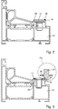
Figur 3 dargestellt ist, ist erkennbar wie die Falle 24 bei ihrer Bewegung in Richtung des Pfeils 32 auf den Aufsatz 26 aufläuft. Dabei berührt die Fallenschräge 34 den Aufsatz 26, bevor die Fallenschräge 34 oder ein anderer Teil der Falle 24 am Rahmen 10 anschlägt. - Dies ist auch deutlich in der vergrößerten Wiedergabe des Ausschnitts IV in der
Figur 4 dargestellt. Insbesondere weist der Aufsatz 26 eine erste Rampe 36 auf, deren Winkel dem Winkel der Fallenschräge 34 entspricht. Der ersten Rampe 36 gegenüber läuft der Aufsatz 26 über eine zweite Rampe 38 in die Oberseite 30 des Schließblechs 14 aus. Hierdurch wird ein geräuscharmes Ablegen der Falle 24 auf dem Schließblech 14 ermöglicht. - Wichtig ist noch, dass der Aufsatz 26 einteilig aus dem Material des Schließblechs 14 geprägt wird, indem an der Seitenkante 16 sich befindendes Material verdrängt wird, was in
Figur 3 erkennbar ist. Dieser Vorgang erfolgt dadurch, dass das Schließblech 14 mit seiner Oberseite 30 in ein Prägegesenk eingelegt wird und die Rückseite und die Seitenkante 16 mit einem Prägestempel bearbeitet werden.
Claims (7)
- Schließblech (14) oder -leiste mit einer Aussparung (20) zur Aufnahme einer Falle (24), wobei das Schließblech (14) oder die -leiste in eine Einsenkung (12) eines Rahmens (10) einsetzbar ist und der Rahmen (10) einen der Fallenschräge (34) der auflaufenden Falle (24) zugewandten Steg (18) aufweist, hinter welchem im montierten Zustand sich das Schließblech (14) oder die Schließleiste befindet, wobei das Schließblech (14) oder die Schließleiste im Bereich der Aussparung (20) einen Aufsatz (26) aufweist, der im montierten Zustand den Steg (18) in Richtung der auflaufenden Falle (24) übergreift, wobei der Aufsatz (26) aus dem Material des Schließblechs (14) oder der Schließleiste herausgeprägt ist, dadurch gekennzeichnet, dass zwischen der Aussparung (20) und der am Steg (18) anliegenden Seitenkante (16) sich eine Brücke erstreckt und der Aufsatz (26) sich im montierten Zustand über den Steg (18) und über die Seitenkante (16) bis über einen Teil der Brücke erstreckt.
- Schließblech oder -leiste nach Anspruch 1 dadurch gekennzeichnet, dass der Aufsatz (26) den Steg (18) in Fallenauflaufrichtung vollständig übergreift.
- Schließblech oder -leiste nach einem der vorhergehenden Ansprüche, dadurch gekennzeichnet, dass der Aufsatz (26) eine erste Rampe (36) für die auflaufende Falle (24) aufweist.
- Schließblech oder -leiste nach einem der vorhergehenden Ansprüche, dadurch gekennzeichnet, dass der Aufsatz (26) auf seiner der Aussparung (20) zugewandten Seite eine zweite Rampe (38) aufweist.
- Verfahren zur Herstellung eines Schließblechs (14) oder einer Schließleiste nach einem der vorhergehenden Ansprüche, dadurch gekennzeichnet, dass das Schließblech (14) mit der Sicht- oder Oberseite (30) in ein Prägegesenk eingelegt und von der Rückseite (40) derart bearbeitet wird, dass das Material des Aufsatzes (26) einem Bereich der dem Steg (18) zugewandten Seitenkante (16) entnommen wird.
- Verfahren nach Anspruch 5, dadurch gekennzeichnet, dass auf der bezüglich der Aussparung (20) gegenüberliegenden Brücke eine Vertiefung in die Rückseite (40) eingebracht wird.
- Verfahren nach Anspruch 6, dadurch gekennzeichnet, dass die Vertiefung sich über die gesamte Breite der Brücke erstreckt.
Priority Applications (1)
| Application Number | Priority Date | Filing Date | Title |
|---|---|---|---|
| EP13151042.2A EP2754789B1 (de) | 2013-01-11 | 2013-01-11 | Schließblech oder -leiste und Verfahren zur Herstellung eines derartigen Schließblechs oder einer derartigen Schließleiste |
Applications Claiming Priority (1)
| Application Number | Priority Date | Filing Date | Title |
|---|---|---|---|
| EP13151042.2A EP2754789B1 (de) | 2013-01-11 | 2013-01-11 | Schließblech oder -leiste und Verfahren zur Herstellung eines derartigen Schließblechs oder einer derartigen Schließleiste |
Publications (2)
| Publication Number | Publication Date |
|---|---|
| EP2754789A1 EP2754789A1 (de) | 2014-07-16 |
| EP2754789B1 true EP2754789B1 (de) | 2016-04-06 |
Family
ID=47563203
Family Applications (1)
| Application Number | Title | Priority Date | Filing Date |
|---|---|---|---|
| EP13151042.2A Not-in-force EP2754789B1 (de) | 2013-01-11 | 2013-01-11 | Schließblech oder -leiste und Verfahren zur Herstellung eines derartigen Schließblechs oder einer derartigen Schließleiste |
Country Status (1)
| Country | Link |
|---|---|
| EP (1) | EP2754789B1 (de) |
Families Citing this family (1)
| Publication number | Priority date | Publication date | Assignee | Title |
|---|---|---|---|---|
| CN110185320B (zh) * | 2019-06-12 | 2024-04-16 | 上海钧正网络科技有限公司 | 一种电控锁体及共享车辆系统 |
Family Cites Families (8)
| Publication number | Priority date | Publication date | Assignee | Title |
|---|---|---|---|---|
| US3241873A (en) * | 1963-12-17 | 1966-03-22 | Russell | Snap-on strike box |
| DE4341612A1 (de) | 1993-12-07 | 1994-06-01 | Eberhard Vos | Sichere Falle für Schließeinrichtungen = Sicherheitsfalle |
| DE10215014C5 (de) * | 2002-04-05 | 2010-02-04 | Carl Fuhr Gmbh & Co. Kg | Schließleiste, insbesondere Schließleiste mit einem Türöffner, für ein Türschloss |
| DE102004012112B3 (de) * | 2004-03-12 | 2005-08-25 | Carl Fuhr Gmbh & Co. Kg | Schließleiste mit einem Türöffner für ein Türschloss |
| DE102005012856A1 (de) * | 2005-03-17 | 2006-09-28 | Carl Fuhr Gmbh & Co. Kg | Schliessleistenaggregat für ein Türschloss |
| DE102008032072A1 (de) * | 2008-07-08 | 2010-01-14 | Assa Abloy Sicherheitstechnik Gmbh | Schließblech und Stulp und deren Verwendung |
| DE202010008334U1 (de) * | 2010-08-23 | 2010-10-28 | Baugruppentechnik Pollmeier Gmbh | Schließblech für eine Türzarge |
| DE202010008345U1 (de) * | 2010-08-24 | 2011-11-28 | Hücking GmbH | Stulp für ein Schließblech |
-
2013
- 2013-01-11 EP EP13151042.2A patent/EP2754789B1/de not_active Not-in-force
Also Published As
| Publication number | Publication date |
|---|---|
| EP2754789A1 (de) | 2014-07-16 |
Similar Documents
| Publication | Publication Date | Title |
|---|---|---|
| EP2864566A1 (de) | Einbruchhemmende schiebetür | |
| DE202009001436U1 (de) | Schließblech mit einer Gleitschließplatte | |
| DE3735637A1 (de) | Abstandselement | |
| EP2113624B1 (de) | Tür- oder Fenstersicherungsvorrichtung | |
| EP2146029B1 (de) | Türrahmenprofil mit einer Schliessleiste | |
| DE102019106101B4 (de) | Insektenschutztür | |
| DE102013107650A1 (de) | Mitteldichtungsblock für Hebe-Schiebe-Tür- oder Fenster | |
| EP1703043B1 (de) | Schliessleistenaggregat für ein Türschloss | |
| EP2754789A1 (de) | Schließblech oder -leiste und Verfahren zur Herstellung eines derartigen Schließblechs oder einer derartigen Schließleiste | |
| EP3168394B1 (de) | Sperrkloben für einen türöffner oder ein schliessblech | |
| DE202008015517U1 (de) | Schließleiste für eine Schließanlage mit Mehrfachverriegelung | |
| DE202012004988U1 (de) | Bauelement | |
| DE202015102101U1 (de) | Schließblech, Anordnung mit einem solchen Schließblech und Türzarge mit einem solchen Schließblech | |
| DE19923151A1 (de) | Einbruchsicherungsvorrichtung, insbesondere für Türen | |
| DE102008032072A1 (de) | Schließblech und Stulp und deren Verwendung | |
| DE8218022U1 (de) | Zargenteil mit schliessblech und/oder schliessplatte | |
| DE19957358A1 (de) | Verfahren zum Bestücken eines Fensterrahmens mit einem Treibstangenbeschlagsystem und dazu geeignete Teile | |
| DE202010004012U1 (de) | Befestigungselement für Stulpschienenbeschläge für Fenster und Türen | |
| EP2339095A2 (de) | Tür, insbesondere Kunstofftür, mit einer Schlosskastensicherung sowie Schlosskastensicherung dafür | |
| DE60300577T2 (de) | Riegelbeschlag für Schiebeflügel | |
| DE60000324T2 (de) | Beschlagelement bzw. Schliessblech oder anderes in einer einklemmenden "u" oder "t" formigen Nut zu befestigen | |
| DE7903658U1 (de) | Schliessblech, insbesondere winkel- schliessblech fuer tueren | |
| EP2133498B1 (de) | Stulpschiene und Fenster oder Tür mit einer Stulpschiene | |
| DE102013108524A1 (de) | Befestigungsvorrichtung für einen Schutzflügel einer Schiebetür | |
| DE102014118511A1 (de) | Fallenauswerfer mit einstellbarem Kontaktelement |
Legal Events
| Date | Code | Title | Description |
|---|---|---|---|
| PUAI | Public reference made under article 153(3) epc to a published international application that has entered the european phase |
Free format text: ORIGINAL CODE: 0009012 |
|
| 17P | Request for examination filed |
Effective date: 20140108 |
|
| AK | Designated contracting states |
Kind code of ref document: A1 Designated state(s): AL AT BE BG CH CY CZ DE DK EE ES FI FR GB GR HR HU IE IS IT LI LT LU LV MC MK MT NL NO PL PT RO RS SE SI SK SM TR |
|
| AX | Request for extension of the european patent |
Extension state: BA ME |
|
| GRAP | Despatch of communication of intention to grant a patent |
Free format text: ORIGINAL CODE: EPIDOSNIGR1 |
|
| INTG | Intention to grant announced |
Effective date: 20150715 |
|
| INTG | Intention to grant announced |
Effective date: 20151119 |
|
| GRAS | Grant fee paid |
Free format text: ORIGINAL CODE: EPIDOSNIGR3 |
|
| GRAA | (expected) grant |
Free format text: ORIGINAL CODE: 0009210 |
|
| AK | Designated contracting states |
Kind code of ref document: B1 Designated state(s): AL AT BE BG CH CY CZ DE DK EE ES FI FR GB GR HR HU IE IS IT LI LT LU LV MC MK MT NL NO PL PT RO RS SE SI SK SM TR |
|
| REG | Reference to a national code |
Ref country code: GB Ref legal event code: FG4D Free format text: NOT ENGLISH |
|
| REG | Reference to a national code |
Ref country code: AT Ref legal event code: REF Ref document number: 788032 Country of ref document: AT Kind code of ref document: T Effective date: 20160415 Ref country code: CH Ref legal event code: EP |
|
| REG | Reference to a national code |
Ref country code: CH Ref legal event code: NV Representative=s name: DREISS PATENTANWAELTE PARTG MBB, DE |
|
| REG | Reference to a national code |
Ref country code: IE Ref legal event code: FG4D Free format text: LANGUAGE OF EP DOCUMENT: GERMAN |
|
| REG | Reference to a national code |
Ref country code: DE Ref legal event code: R096 Ref document number: 502013002414 Country of ref document: DE |
|
| REG | Reference to a national code |
Ref country code: NL Ref legal event code: FP |
|
| REG | Reference to a national code |
Ref country code: LT Ref legal event code: MG4D |
|
| PG25 | Lapsed in a contracting state [announced via postgrant information from national office to epo] |
Ref country code: FI Free format text: LAPSE BECAUSE OF FAILURE TO SUBMIT A TRANSLATION OF THE DESCRIPTION OR TO PAY THE FEE WITHIN THE PRESCRIBED TIME-LIMIT Effective date: 20160406 Ref country code: NO Free format text: LAPSE BECAUSE OF FAILURE TO SUBMIT A TRANSLATION OF THE DESCRIPTION OR TO PAY THE FEE WITHIN THE PRESCRIBED TIME-LIMIT Effective date: 20160706 Ref country code: PL Free format text: LAPSE BECAUSE OF FAILURE TO SUBMIT A TRANSLATION OF THE DESCRIPTION OR TO PAY THE FEE WITHIN THE PRESCRIBED TIME-LIMIT Effective date: 20160406 Ref country code: IS Free format text: LAPSE BECAUSE OF FAILURE TO SUBMIT A TRANSLATION OF THE DESCRIPTION OR TO PAY THE FEE WITHIN THE PRESCRIBED TIME-LIMIT Effective date: 20160806 Ref country code: LT Free format text: LAPSE BECAUSE OF FAILURE TO SUBMIT A TRANSLATION OF THE DESCRIPTION OR TO PAY THE FEE WITHIN THE PRESCRIBED TIME-LIMIT Effective date: 20160406 |
|
| PG25 | Lapsed in a contracting state [announced via postgrant information from national office to epo] |
Ref country code: ES Free format text: LAPSE BECAUSE OF FAILURE TO SUBMIT A TRANSLATION OF THE DESCRIPTION OR TO PAY THE FEE WITHIN THE PRESCRIBED TIME-LIMIT Effective date: 20160406 Ref country code: GR Free format text: LAPSE BECAUSE OF FAILURE TO SUBMIT A TRANSLATION OF THE DESCRIPTION OR TO PAY THE FEE WITHIN THE PRESCRIBED TIME-LIMIT Effective date: 20160707 Ref country code: SE Free format text: LAPSE BECAUSE OF FAILURE TO SUBMIT A TRANSLATION OF THE DESCRIPTION OR TO PAY THE FEE WITHIN THE PRESCRIBED TIME-LIMIT Effective date: 20160406 Ref country code: PT Free format text: LAPSE BECAUSE OF FAILURE TO SUBMIT A TRANSLATION OF THE DESCRIPTION OR TO PAY THE FEE WITHIN THE PRESCRIBED TIME-LIMIT Effective date: 20160808 Ref country code: HR Free format text: LAPSE BECAUSE OF FAILURE TO SUBMIT A TRANSLATION OF THE DESCRIPTION OR TO PAY THE FEE WITHIN THE PRESCRIBED TIME-LIMIT Effective date: 20160406 Ref country code: LV Free format text: LAPSE BECAUSE OF FAILURE TO SUBMIT A TRANSLATION OF THE DESCRIPTION OR TO PAY THE FEE WITHIN THE PRESCRIBED TIME-LIMIT Effective date: 20160406 Ref country code: RS Free format text: LAPSE BECAUSE OF FAILURE TO SUBMIT A TRANSLATION OF THE DESCRIPTION OR TO PAY THE FEE WITHIN THE PRESCRIBED TIME-LIMIT Effective date: 20160406 |
|
| REG | Reference to a national code |
Ref country code: DE Ref legal event code: R097 Ref document number: 502013002414 Country of ref document: DE |
|
| REG | Reference to a national code |
Ref country code: FR Ref legal event code: PLFP Year of fee payment: 5 |
|
| PG25 | Lapsed in a contracting state [announced via postgrant information from national office to epo] |
Ref country code: DK Free format text: LAPSE BECAUSE OF FAILURE TO SUBMIT A TRANSLATION OF THE DESCRIPTION OR TO PAY THE FEE WITHIN THE PRESCRIBED TIME-LIMIT Effective date: 20160406 Ref country code: RO Free format text: LAPSE BECAUSE OF FAILURE TO SUBMIT A TRANSLATION OF THE DESCRIPTION OR TO PAY THE FEE WITHIN THE PRESCRIBED TIME-LIMIT Effective date: 20160406 Ref country code: SK Free format text: LAPSE BECAUSE OF FAILURE TO SUBMIT A TRANSLATION OF THE DESCRIPTION OR TO PAY THE FEE WITHIN THE PRESCRIBED TIME-LIMIT Effective date: 20160406 Ref country code: EE Free format text: LAPSE BECAUSE OF FAILURE TO SUBMIT A TRANSLATION OF THE DESCRIPTION OR TO PAY THE FEE WITHIN THE PRESCRIBED TIME-LIMIT Effective date: 20160406 Ref country code: CZ Free format text: LAPSE BECAUSE OF FAILURE TO SUBMIT A TRANSLATION OF THE DESCRIPTION OR TO PAY THE FEE WITHIN THE PRESCRIBED TIME-LIMIT Effective date: 20160406 |
|
| PLBE | No opposition filed within time limit |
Free format text: ORIGINAL CODE: 0009261 |
|
| STAA | Information on the status of an ep patent application or granted ep patent |
Free format text: STATUS: NO OPPOSITION FILED WITHIN TIME LIMIT |
|
| PG25 | Lapsed in a contracting state [announced via postgrant information from national office to epo] |
Ref country code: SM Free format text: LAPSE BECAUSE OF FAILURE TO SUBMIT A TRANSLATION OF THE DESCRIPTION OR TO PAY THE FEE WITHIN THE PRESCRIBED TIME-LIMIT Effective date: 20160406 |
|
| REG | Reference to a national code |
Ref country code: DE Ref legal event code: R082 Ref document number: 502013002414 Country of ref document: DE |
|
| 26N | No opposition filed |
Effective date: 20170110 |
|
| PG25 | Lapsed in a contracting state [announced via postgrant information from national office to epo] |
Ref country code: BE Free format text: LAPSE BECAUSE OF NON-PAYMENT OF DUE FEES Effective date: 20170131 Ref country code: SI Free format text: LAPSE BECAUSE OF FAILURE TO SUBMIT A TRANSLATION OF THE DESCRIPTION OR TO PAY THE FEE WITHIN THE PRESCRIBED TIME-LIMIT Effective date: 20160406 |
|
| GBPC | Gb: european patent ceased through non-payment of renewal fee |
Effective date: 20170111 |
|
| PG25 | Lapsed in a contracting state [announced via postgrant information from national office to epo] |
Ref country code: MC Free format text: LAPSE BECAUSE OF FAILURE TO SUBMIT A TRANSLATION OF THE DESCRIPTION OR TO PAY THE FEE WITHIN THE PRESCRIBED TIME-LIMIT Effective date: 20160406 |
|
| REG | Reference to a national code |
Ref country code: IE Ref legal event code: MM4A |
|
| PG25 | Lapsed in a contracting state [announced via postgrant information from national office to epo] |
Ref country code: GB Free format text: LAPSE BECAUSE OF NON-PAYMENT OF DUE FEES Effective date: 20170111 Ref country code: LU Free format text: LAPSE BECAUSE OF NON-PAYMENT OF DUE FEES Effective date: 20170111 |
|
| REG | Reference to a national code |
Ref country code: FR Ref legal event code: PLFP Year of fee payment: 6 |
|
| REG | Reference to a national code |
Ref country code: BE Ref legal event code: MM Effective date: 20170131 |
|
| PG25 | Lapsed in a contracting state [announced via postgrant information from national office to epo] |
Ref country code: IE Free format text: LAPSE BECAUSE OF NON-PAYMENT OF DUE FEES Effective date: 20170111 |
|
| PG25 | Lapsed in a contracting state [announced via postgrant information from national office to epo] |
Ref country code: MT Free format text: LAPSE BECAUSE OF FAILURE TO SUBMIT A TRANSLATION OF THE DESCRIPTION OR TO PAY THE FEE WITHIN THE PRESCRIBED TIME-LIMIT Effective date: 20160406 |
|
| PG25 | Lapsed in a contracting state [announced via postgrant information from national office to epo] |
Ref country code: AL Free format text: LAPSE BECAUSE OF FAILURE TO SUBMIT A TRANSLATION OF THE DESCRIPTION OR TO PAY THE FEE WITHIN THE PRESCRIBED TIME-LIMIT Effective date: 20160406 |
|
| PG25 | Lapsed in a contracting state [announced via postgrant information from national office to epo] |
Ref country code: HU Free format text: LAPSE BECAUSE OF FAILURE TO SUBMIT A TRANSLATION OF THE DESCRIPTION OR TO PAY THE FEE WITHIN THE PRESCRIBED TIME-LIMIT; INVALID AB INITIO Effective date: 20130111 |
|
| PG25 | Lapsed in a contracting state [announced via postgrant information from national office to epo] |
Ref country code: BG Free format text: LAPSE BECAUSE OF FAILURE TO SUBMIT A TRANSLATION OF THE DESCRIPTION OR TO PAY THE FEE WITHIN THE PRESCRIBED TIME-LIMIT Effective date: 20160406 |
|
| PG25 | Lapsed in a contracting state [announced via postgrant information from national office to epo] |
Ref country code: CY Free format text: LAPSE BECAUSE OF NON-PAYMENT OF DUE FEES Effective date: 20160406 |
|
| PG25 | Lapsed in a contracting state [announced via postgrant information from national office to epo] |
Ref country code: MK Free format text: LAPSE BECAUSE OF FAILURE TO SUBMIT A TRANSLATION OF THE DESCRIPTION OR TO PAY THE FEE WITHIN THE PRESCRIBED TIME-LIMIT Effective date: 20160406 |
|
| PGFP | Annual fee paid to national office [announced via postgrant information from national office to epo] |
Ref country code: AT Payment date: 20200122 Year of fee payment: 8 Ref country code: NL Payment date: 20200121 Year of fee payment: 8 Ref country code: IT Payment date: 20200131 Year of fee payment: 8 Ref country code: DE Payment date: 20200121 Year of fee payment: 8 |
|
| PGFP | Annual fee paid to national office [announced via postgrant information from national office to epo] |
Ref country code: CH Payment date: 20200121 Year of fee payment: 8 |
|
| PGFP | Annual fee paid to national office [announced via postgrant information from national office to epo] |
Ref country code: FR Payment date: 20200121 Year of fee payment: 8 Ref country code: TR Payment date: 20200110 Year of fee payment: 8 |
|
| REG | Reference to a national code |
Ref country code: DE Ref legal event code: R119 Ref document number: 502013002414 Country of ref document: DE |
|
| REG | Reference to a national code |
Ref country code: CH Ref legal event code: PL |
|
| REG | Reference to a national code |
Ref country code: NL Ref legal event code: MM Effective date: 20210201 |
|
| REG | Reference to a national code |
Ref country code: AT Ref legal event code: MM01 Ref document number: 788032 Country of ref document: AT Kind code of ref document: T Effective date: 20210111 |
|
| PG25 | Lapsed in a contracting state [announced via postgrant information from national office to epo] |
Ref country code: NL Free format text: LAPSE BECAUSE OF NON-PAYMENT OF DUE FEES Effective date: 20210201 Ref country code: FR Free format text: LAPSE BECAUSE OF NON-PAYMENT OF DUE FEES Effective date: 20210131 Ref country code: AT Free format text: LAPSE BECAUSE OF NON-PAYMENT OF DUE FEES Effective date: 20210111 |
|
| PG25 | Lapsed in a contracting state [announced via postgrant information from national office to epo] |
Ref country code: DE Free format text: LAPSE BECAUSE OF NON-PAYMENT OF DUE FEES Effective date: 20210803 Ref country code: CH Free format text: LAPSE BECAUSE OF NON-PAYMENT OF DUE FEES Effective date: 20210131 Ref country code: LI Free format text: LAPSE BECAUSE OF NON-PAYMENT OF DUE FEES Effective date: 20210131 |
|
| PG25 | Lapsed in a contracting state [announced via postgrant information from national office to epo] |
Ref country code: IT Free format text: LAPSE BECAUSE OF NON-PAYMENT OF DUE FEES Effective date: 20210111 |
|
| PG25 | Lapsed in a contracting state [announced via postgrant information from national office to epo] |
Ref country code: TR Free format text: LAPSE BECAUSE OF NON-PAYMENT OF DUE FEES Effective date: 20210111 |