EP2754635B1 - Turmdrehkran - Google Patents
Turmdrehkran Download PDFInfo
- Publication number
- EP2754635B1 EP2754635B1 EP13005841.5A EP13005841A EP2754635B1 EP 2754635 B1 EP2754635 B1 EP 2754635B1 EP 13005841 A EP13005841 A EP 13005841A EP 2754635 B1 EP2754635 B1 EP 2754635B1
- Authority
- EP
- European Patent Office
- Prior art keywords
- tower
- crane
- profile
- section
- cross
- Prior art date
- Legal status (The legal status is an assumption and is not a legal conclusion. Google has not performed a legal analysis and makes no representation as to the accuracy of the status listed.)
- Active
Links
- 238000007373 indentation Methods 0.000 claims description 27
- 230000007704 transition Effects 0.000 claims description 14
- 239000007787 solid Substances 0.000 description 3
- 230000001154 acute effect Effects 0.000 description 2
- 238000005452 bending Methods 0.000 description 2
- 239000000835 fiber Substances 0.000 description 2
- 238000004519 manufacturing process Methods 0.000 description 2
- 230000007935 neutral effect Effects 0.000 description 2
- 239000011324 bead Substances 0.000 description 1
- 230000015572 biosynthetic process Effects 0.000 description 1
- 230000001419 dependent effect Effects 0.000 description 1
- 230000000694 effects Effects 0.000 description 1
- 238000005516 engineering process Methods 0.000 description 1
- 238000003466 welding Methods 0.000 description 1
Images

Classifications
-
- B—PERFORMING OPERATIONS; TRANSPORTING
- B66—HOISTING; LIFTING; HAULING
- B66C—CRANES; LOAD-ENGAGING ELEMENTS OR DEVICES FOR CRANES, CAPSTANS, WINCHES, OR TACKLES
- B66C23/00—Cranes comprising essentially a beam, boom, or triangular structure acting as a cantilever and mounted for translatory of swinging movements in vertical or horizontal planes or a combination of such movements, e.g. jib-cranes, derricks, tower cranes
- B66C23/18—Cranes comprising essentially a beam, boom, or triangular structure acting as a cantilever and mounted for translatory of swinging movements in vertical or horizontal planes or a combination of such movements, e.g. jib-cranes, derricks, tower cranes specially adapted for use in particular purposes
- B66C23/26—Cranes comprising essentially a beam, boom, or triangular structure acting as a cantilever and mounted for translatory of swinging movements in vertical or horizontal planes or a combination of such movements, e.g. jib-cranes, derricks, tower cranes specially adapted for use in particular purposes for use on building sites; constructed, e.g. with separable parts, to facilitate rapid assembly or dismantling, for operation at successively higher levels, for transport by road or rail
- B66C23/34—Self-erecting cranes, i.e. with hoisting gear adapted for crane erection purposes
- B66C23/342—Self-erecting cranes, i.e. with hoisting gear adapted for crane erection purposes with telescopic elements
Definitions
- the present invention relates to a tower crane with a tower on which a boom is mounted, wherein the tower comprises at least one tower part, the tower cross-sectional profile tower front and rear sides, through which passes a crane plane containing the boom longitudinal axis and the longitudinal axis of the tower.
- tower cranes it has become known not form the tower parts as a lattice work, but as a thin solid wall profile, especially when the tower is telescopic.
- Such telescopic towers are used in particular in mobile tower cranes, in which the tower sits on a trained as a vehicle undercarriage, telescoped and can be relocated to be quickly transported from one location to the next.
- Such tower profiles can be used in an advantageous manner generally in fast-erecting cranes, cf. for example CN 101920914 A or NL 1032591 A ,
- the tower carries a boom, which protrudes from a turret front, the cantilever can be aligned approximately horizontally and carry a trolley, or can also be designed as a rocker in the manner of a Nadelauslegers from the top of the hoist runs off.
- a plane passing through the longitudinal axis of the tower and at the same time through the boom can hereby be the crane plane of the tower cross-sectional profile form and at the same time set the tower front and rear side, which are both cut by said crane plane.
- the front of the tower here means the tower side, from which the main boom protrudes, while the tower back is facing away from the main boom.
- the boom is usually held by a bracing, which can be performed over a projecting from the tower rear bracing or counter-arm.
- the present invention has for its object to provide an improved tower crane of the type mentioned, which avoids the disadvantages of the prior art and the latter develops advantageously.
- improved tower crane of the type mentioned which avoids the disadvantages of the prior art and the latter develops advantageously.
- increased BeulsteifIER be achieved without affecting the functionality of telescoping the tower and the necessary components such as pulleys or cable guides on the tower and the like.
- the tower cross-sectional profile in the region of the side edges between Turmvorder- and - discloses a step-shaped cross-sectional taper, which tapers the profile width transversely to the said cranial plane of the cross-sectional profile of a wider soflankenstoffabterrorism to a narrower soflankenendabterrorism adjacent to the transition to the tower back or front of the tower, stepwise.
- a bead-like bulge can also be provided on the tower front side and / or the tower rear side which can extend parallel to the longitudinal axis of the tower in the manner of a longitudinal bead.
- the hollow indentations or bulges are advantageously arranged lying in the crane plane of the tower cross section profile, but could possibly also be provided offset thereto, in which case several such indentations may be provided symmetrically offset on the same side of the tower to maintain the symmetry with respect to the crane plane. Surprisingly, however, an increase in the buckling stiffness can also be achieved without preserving the symmetry.
- the indentations or protrusions on the front and / or rear of the tower can also be arranged offset relative to the said crane plane, so that there is an asymmetrical tower cross-section with respect to the crane plane.
- a hollow indentation and / or a bulge-like bulge can be provided both in the front of the tower and in the rear of the tower, for example, in the middle and thus lying in the crane plane of the cross-sectional profile.
- the Turmvorder- and backs - roughly speaking - get a concave design, while the side edges - also roughly speaking - may have a convex bulging contouring.
- This alternating over the profile cross-section side contouring can achieve a total high buckling stiffness even with thin walls and thus very low weight.
- the tower cross section or the respective tower part can in this case be composed of a plurality of half or partial shells, which can be rigidly and / or materially connected to one another, in particular welded together.
- the respective tower part can be composed of two half-shells in order to enable a simple production with relatively little welding work.
- the tower part may also be composed of three, four or more shell parts.
- the connecting seam or the interfaces between the partial shells can in principle be arranged differently.
- the tower profile may be split in half along a median plane extending transversely to the crane plane, so that the connecting seams run, as it were, along the neutral fiber in the case of bends in the cantilever plane.
- the connecting seams between the shell parts are not provided in the corner regions of the tower cross-sectional profile, but rather offset from the said corner regions, provided on the front and rear sides or the side flanks of the tower cross-sectional profile.
- the mentioned side edges with the step-shaped cross-sectional taper are asymmetrically contoured in a further development of the invention with respect to a plane perpendicular to the crane plane of the cross-sectional profile.
- a cross-sectional taper can be provided towards the back of the tower, while no step-shaped discontinuity or S-shaped transition area is provided towards the front of the tower.
- the tower section profile can also be used rotated by 180 °.
- a cross-sectional taper can be provided towards the front of the tower, while no stepped cross-section jump or S-shaped transition region is provided towards the rear of the tower.
- the side edge central portion to the turret side in a tapered and / or rounded side edge end portion adjacent to the turret front pass over, in which side edge end portion advantageously the profile width from the side edge central portion from the tower front side continuously tapers ,
- the side flank sections adjoining the step-shaped cross-sectional tapering in the side flanks may in principle be contoured differently, but in a further development of the invention may advantageously have a straight contour profile.
- the side edges accordingly have in development of the invention two - viewed in profile cross section - just trained flank sections, which are offset from one another by the stepped transition region.
- the said straight flank sections can run parallel to one another and be connected to one another by a step-shaped or S-shaped transition region in which the curvature changes in opposite directions or has two profile transitions curved in opposite directions or folded or folded.
- the aforementioned straight side flank sections which adjoin the cross-sectional step, extend at least approximately parallel to the crane plane of the profile cross section.
- the length of the straight course of said side flank sections can basically be dimensioned differently, wherein in a further development of the invention, the straight, adjoining the cross-sectional tapering side flank sections can extend straight over at least 15%, preferably about 20% to 45% of the maximum profile height of the tower part.
- the said maximum profile height of the tower part is measured parallel to the crane plane and represents the maximum extent of the cross-sectional profile in a direction parallel to the axis of symmetry, which forms the cutting axis of the crane plane and cross-sectional plane.
- the said straight side flank sections which adjoin the cross-sectional step, may be formed differently in length compared to each other in development of the invention, wherein preferably the straight side edge formed central portion extends over a greater length straight than the side edge end portion, the back to the tower connected to the cross-sectional step.
- the length of the straight side edge central portion may be about 120% to 180% of the length of the straight side edge end portion.
- the step-shaped cross-sectional tapering out of the profile center out of the tower back or the tower front side is arranged offset, preferably at about 25% to 40% of the maximum profile height measured from the tower back or front of the tower.
- the step-shaped cross-sectional taper does not lie in the region of a transverse axis, which perpendicularly intersects the axis of symmetry of the profile cross-section in the middle, but is offset relative to this transverse axis toward the tower rear side or tower front side.
- a transverse line connecting the step-shaped cross-sectional tapers in the right and left side flanks may be the axis of symmetry in such a way cut that the Symmetrieachsenmaschine are divided approximately in the ratio of 1/3 to 2/3.
- the cross-sectional taper can be dimensioned differently in the side edges in order to achieve a noticeable effect on the buckling stiffness, but on the other hand proves to be unobjectionable to the available tower part interior, for example for telescopic parts or power guideways, it proves to be advantageous if said step-shaped cross-sectional taper in the side edges has a step height of about 1/8 to 1/12 of half the maximum profile width of the cross-sectional profile, said step height and the maximum profile width are each measured transversely to the crane plane of the tower part.
- a maximum profile width is transverse to the crane plane in the region of the side edge middle portion, in particular can be measured at about half the profile height, ie. the side flanks bulge the most over the profiling means.
- the maximum profile height which is measured parallel to the axis of symmetry, is not in the region of the axis of symmetry due to the aforesaid preferably centrally located fillets in the turret front and / or rear sides
- the maximum profile width lies approximately centrally transversely to the symmetry axis.
- the tower front and back sides are grooved in the middle, while the side edges bulge out in the middle or define their maximum profile width extension there.
- the maximum profile width of the tower profile cross-section transverse to the crane plane may be greater than the maximum profile height parallel to the crane plane, wherein preferably the maximum profile height may be about 75% to 95%, in particular about 80% to 90% of the maximum profile width.
- the maximum profile height may be about 75% to 95%, in particular about 80% to 90% of the maximum profile width.
- the tower front side and the tower rear side can be formed differently from each other.
- the profile sections adjoining the groove-like indentation or bead-like bulging can be contoured or aligned differently.
- adjoining the indentation or bulge flank portions of the tower back can be straight and aligned parallel to each other, in particular lie in a common plane, so that the tower rear side of the groove indentation or bulge apart substantially flat.
- flank sections of the tower front side adjoining the indentation or bulge in the front of the tower can be designed to run straight, but be set at an acute angle to one another, so that the front of the tower is slightly sloping away from the edges of the hollow indentation or bulge the flank sections of the tower front side adjoining the groove-like depression extend at an obtuse angle to one another or fall off towards the side flanks in the manner of flat roof flanks.
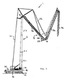
- the tower crane 1 may be formed as a mobile or vehicle crane, which includes a designed as a truck undercarriage 16, for example, see. Fig. 1 , can be supported and leveled for crane operation on support legs 17. If the crane is designed as a UntenFer, like this Fig. 1 shows can sit on said undercarriage 16 about an upright axle rotatable upper carriage 18, on the one hand, the tower 2 of the tower crane 1 is supported and on the other hand, the usual crane units such as winches, hydraulic or ballast weights and the like can be arranged.
- the tower 2 can be pivoted on the above-mentioned superstructure 18 about a horizontal rocking axis 19, so that the tower 2 in the contracted state can be placed on the uppercarriage and possibly additional supports 20 on the undercarriage 16 in a lying position.
- a boom 3 is hinged, which may extend approximately horizontally in the intended working position, but may also be designed as a tiltable luffing jib.
- the tower 2 and the boom 3 can be braced in a conventional manner by tower and boom bracing 21 and 22 respectively.
- the boom 3 can be composed of a plurality of jib parts 3a, 3b and 3c, which can be zigzag collapsible or slidable or otherwise be moved together.
- a load hook 23 can be drained in a conventional manner via a hoist rope.
- Said tower 2 can be composed of several tower parts 2.1, 2.2 and 2.3 and thereby be telescopic, so that said tower parts can be pushed into each other.
- the tower parts can be 2.2 and 2.3 successively extendable from the Turmfußteil 2.1, but if necessary, but could also be provided vice versa, the telescope parts successively to be able to drive out of the tower top.
- the suitably provided Teleskopierantrieb can basically be designed differently, for example by arranged in the interior of the tower 2 cables or hydraulic cylinder or combination thereof.
- the telescoping tower parts can have 2.1, 2.2 and 2.3 each other in the course of corresponding contours or have matched contours that differ only in size or in the diameter measure, so that they are movable into each other.
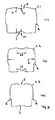
- said tower parts have a profile cross-section deviating from the circular shape and also from a regular rectangular shape or rounded rectangular shape and comprising a crane plane defined by the longitudinal axis of the tower 2 and the boom 3 and thus by the tower front side 2V and the rear side of the tower 2H goes.
- the show Figures 2 and 3 the profile central axis 5, which is the cutting axis of said crane plane and the vertical axis of the tower 2 profile cross-sectional plane, the plane of the Figures 2 and 3 corresponds, results.
- the tower cross section according to the drawing has a symmetry between the right and left side of the tower, but not between the front of the tower and the back of the tower.
- the tower cross-section does not have to be symmetrical.
- the cross-section jumps to be described on the side flanks in the direction of the profiled center axis 5 can be offset or shifted differently far, so that an asymmetry likewise arises and the buckling stiffness is increased.
- the tower profile cross section still has approximately a rectangular basic shape with four flattened sides, which merge into one another in a rounded manner, but the profile contours of the four pages are modeled or shaped in relief in contrast to an actual rectangle in the manner of a cantilever and / or bending profile.
- the Turmvorder- and -bodfit 2V and 2R each have a groove-like indentation 6 and 7, which extends in each case parallel to the tower longitudinal axis and is arranged centrally in the Turmvorder- or rear side 2V and 2R.
- said symmetry axis 5 can pass centrally through said indentations 6 and 7.
- the recesses 6 and 7 are basically contoured like a channel, wherein they can be designed as a folded frame contour with a flattened bottom and obliquely set edge regions.
- the depth 6T or 7T of the indentations 6 and 7 can in principle vary and, in a further development of the invention, amount to approximately 2% to 8%, in particular approximately 5%, of the maximum profile height H, measured in the direction of the symmetry axis 5.
- the profile width of the recesses or indentations 6 and 7 may be adjusted or varied.
- the indentations 6 and 7 can have a width 6B or 7B which are approximately 1/4 to 1/2 of the maximum profile width B, in particular approximately 1/3 of the maximum profile width, measured perpendicularly to the symmetry axis 5 can, cf. Fig. 3B ,
- the recesses 6 and 7 in the tower front and rear side 2V and 2R can be contoured or dimensioned correspondingly to one another, but may also be contoured and / or dimensioned differently.
- At least one of the indentations 6 or 7 can also be formed as a correspondingly contoured bulge on the front or back of the turret be such that the tower cross-section is not dented concave in a corresponding manner, but convexly protrudes or bulges outward.
- the front of the tower 2V and the rear of the tower 2R are contoured differently from one another in the profile cross-section.
- the profile sections adjoining the indentations 6 and 7 are aligned differently.
- the rear edge edge portions or end portions 13L and 13R adjacent the recess 7 can have a straight course and be arranged parallel to each other, in particular lie in a common plane, so that the tower rear face 2R is substantially flat , planar contour has, in which only the indent 7 is incorporated.
- the angle of attack of said left and right front edge portions 14 L and 14 R to the axis of symmetry 5 may be about 70 ° to 89 °, in particular about 85 °.
- the turrets 2L and 2R of the tower 2, which connect the turret front and rear sides 2V and 2R to one another, are formed in an advantageous development of the invention free of hollow indentations.
- said side flanks 2L and 2R considered overall - roughly speaking - bulge in a side edge central portion 9 and define the largest profile width transverse to the axis of symmetry 5, ie, the side edges are in their central portions not concave as the Turmvorder- and backsides, but extend along the full profile width B.
- the step-shaped cross-sectional tapers 8 can in principle be contoured differently, for example by a harmonic S-shaped transition.
- the cross-sectional tapers 8 may be formed in the manner of a counter-angled crease-corner contour, which includes an oblique transition surface or contour 15, which may have a straight course and each with the adjacent to the cross-sectional taper 8 side flank sections 9 and 11 a blunt Transition angle may include, which transition angle 10 may include about 100 ° to 160 °, in particular about 140 °, see. Fig. 2 ,
- Said step-shaped cross-sectional taper 8 is not provided centrally in the side flanks 2L and 2R, but offset off-center from the tower rear side 2R, said cross-sectional taper 8 being able to be provided at about 30% of the maximum profile height H measured from the tower rear side 2R, cf. , Fig. 2 ,
- the step height 8H of the cross-sectional tapers 8, measured perpendicular to the axis of symmetry 5, can be about 1/8 to 1/12, in particular about 1/10 of half the maximum profile width B, ie about 5% of the total maximum profile width B, cf. Fig. 2 ,
- the adjoining the cross-sectional taper 8 side edge portions, ie, the side edge central portion 9 and the side edge end portion 11 have each have a straight profile course, extending in parallel directions, along straight lines which are offset from each other by the aforementioned step height 8H.
- the said straight side edge middle and end sections 9 and 11 are arranged parallel to the axis of symmetry 5, cf. Fig. 2 ,
- the straight side edge end portion 11 extends over about 20% to 30% of the profile height H, while the straight side edge central portion 9 extends over about 25% to 40% of the profile height H.
- a side flank end section 12 adjoins the straight side flank middle section 9, which in turn has a straight course, but is slightly acute-angled to the axis of symmetry 5, so that the profile width tapers slightly towards the front face 2V, wherein a rounded transition into the front of the tower 2V can be provided out, cf.
- Figures 2 and 3
- tower cross-section profile are also used rotated by 180 ° and / or the Turmvorder- and back sides of the cross-sectional profile are reversed.
- the cross-sectional tapers 8 can taper the profile width towards the front of the tower 2V.
- the roof-shaped profile bevel 14L and 14R may be provided at the tower rear side and the turret front side may be provided with flat profile sections 13L and 13R.
Applications Claiming Priority (1)
| Application Number | Priority Date | Filing Date | Title |
|---|---|---|---|
| DE202013000277.8U DE202013000277U1 (de) | 2013-01-11 | 2013-01-11 | Turmdrehkran |
Publications (2)
| Publication Number | Publication Date |
|---|---|
| EP2754635A1 EP2754635A1 (de) | 2014-07-16 |
| EP2754635B1 true EP2754635B1 (de) | 2015-06-17 |
Family
ID=49884864
Family Applications (1)
| Application Number | Title | Priority Date | Filing Date |
|---|---|---|---|
| EP13005841.5A Active EP2754635B1 (de) | 2013-01-11 | 2013-12-16 | Turmdrehkran |
Country Status (3)
| Country | Link |
|---|---|
| EP (1) | EP2754635B1 (zh) |
| CN (1) | CN103922229B (zh) |
| DE (1) | DE202013000277U1 (zh) |
Family Cites Families (7)
| Publication number | Priority date | Publication date | Assignee | Title |
|---|---|---|---|---|
| US4459786A (en) * | 1981-10-27 | 1984-07-17 | Ro Corporation | Longitudinally bowed transversely polygonal boom for cranes and the like |
| FR2757497B1 (fr) * | 1996-12-23 | 1999-02-12 | Potain Sa | Mature telescopique pour grue a tour |
| DE102006014573B3 (de) | 2006-03-29 | 2007-07-19 | Manitowoc Crane Group France SAS, | Teleskopkran-Auslegerteil mit schwächer und stärker gekrümmten Querschnittssegmenten im oberen Profilteil und im unteren Profilteil |
| NL1032591C2 (nl) * | 2006-09-28 | 2008-03-31 | Mecal Applied Mechanics B V | Hijskraan en werkwijze. |
| DE502008002828D1 (de) | 2007-09-05 | 2011-04-21 | Palfinger Ag | Profilform für einen kranarm |
| CN101920914A (zh) * | 2010-06-19 | 2010-12-22 | 张培霞 | 汽车式上回转塔吊 |
| CN201882816U (zh) * | 2010-12-11 | 2011-06-29 | 郑州新大方重工科技有限公司 | 一种伸缩塔身起重机 |
-
2013
- 2013-01-11 DE DE202013000277.8U patent/DE202013000277U1/de not_active Expired - Lifetime
- 2013-12-16 EP EP13005841.5A patent/EP2754635B1/de active Active
-
2014
- 2014-01-10 CN CN201410012364.1A patent/CN103922229B/zh active Active
Also Published As
| Publication number | Publication date |
|---|---|
| CN103922229B (zh) | 2016-04-27 |
| CN103922229A (zh) | 2014-07-16 |
| DE202013000277U1 (de) | 2014-04-14 |
| EP2754635A1 (de) | 2014-07-16 |
Similar Documents
| Publication | Publication Date | Title |
|---|---|---|
| DE19624312C2 (de) | Teleskopausleger für Fahrzeugkrane | |
| EP3653435B1 (de) | Fahrzeug zum transportieren eines langen transportguts | |
| DE3510590C2 (zh) | ||
| DE1937012A1 (de) | Fahrzeughohlrahmen,insbesondere fuer Kranfahrzeuge | |
| EP1840075B1 (de) | Teleskopkran-Auslegerteil mit schwächer und stärker gekrümmten Querschittssegmenten im oberen Profilteil und im unteren Profilteil | |
| DE19711975B4 (de) | Teleskopausleger für Fahrzeugkrane | |
| EP1090875B1 (de) | Teleskopsausleger für Krane | |
| AT523305A2 (de) | Fahrzeugkran | |
| EP0583552B1 (de) | Teleskopausleger für Fahrzeugkrane o. dgl. | |
| AT515824A1 (de) | Kranträger für einen Kran | |
| EP1321425B1 (de) | Teleskopausleger für einen Fahrzeugkran | |
| DE2040687A1 (de) | Teleskopartig ein- und ausfahrbarer Kranausleger mit kastenfoermigen Auslegerteilen | |
| EP2185462B1 (de) | Profilform für einen kranarm | |
| DE19755355A1 (de) | Teleskopauslegerlagerung mit Prägungen | |
| EP3556718B1 (de) | Autobetonpumpe | |
| EP2754635B1 (de) | Turmdrehkran | |
| DE3015599A1 (de) | Teleskopierbarer kranausleger | |
| EP3184478B1 (de) | Kran | |
| DE2543729C2 (de) | Druckfester Tankcontainer | |
| EP3715557A1 (de) | Knickmast mit mastsegmenten und verfahren zur herstellung eines mastsegmentes | |
| EP3251998B1 (de) | Auslegerprofil für den ausleger eines teleskopkrans | |
| WO2009029965A1 (de) | Profilform für einen kranarm | |
| DE102017127973A1 (de) | Teleskopausleger für einen Kran und Kran mit einem entsprechenden Teleskopausleger | |
| DE102008032976B4 (de) | Teleskopkran-Auslegerteil | |
| DE10056799A1 (de) | Bodenabstützung für fahrbare Krane, Bagger und dergleichen |
Legal Events
| Date | Code | Title | Description |
|---|---|---|---|
| PUAI | Public reference made under article 153(3) epc to a published international application that has entered the european phase |
Free format text: ORIGINAL CODE: 0009012 |
|
| 17P | Request for examination filed |
Effective date: 20131216 |
|
| AK | Designated contracting states |
Kind code of ref document: A1 Designated state(s): AL AT BE BG CH CY CZ DE DK EE ES FI FR GB GR HR HU IE IS IT LI LT LU LV MC MK MT NL NO PL PT RO RS SE SI SK SM TR |
|
| AX | Request for extension of the european patent |
Extension state: BA ME |
|
| R17P | Request for examination filed (corrected) |
Effective date: 20150109 |
|
| GRAP | Despatch of communication of intention to grant a patent |
Free format text: ORIGINAL CODE: EPIDOSNIGR1 |
|
| RIC1 | Information provided on ipc code assigned before grant |
Ipc: B66C 23/34 20060101AFI20150223BHEP |
|
| INTG | Intention to grant announced |
Effective date: 20150316 |
|
| GRAS | Grant fee paid |
Free format text: ORIGINAL CODE: EPIDOSNIGR3 |
|
| GRAA | (expected) grant |
Free format text: ORIGINAL CODE: 0009210 |
|
| RAP3 | Party data changed (applicant data changed or rights of an application transferred) |
Owner name: LIEBHERR-WERK BIBERACH GMBH |
|
| AK | Designated contracting states |
Kind code of ref document: B1 Designated state(s): AL AT BE BG CH CY CZ DE DK EE ES FI FR GB GR HR HU IE IS IT LI LT LU LV MC MK MT NL NO PL PT RO RS SE SI SK SM TR |
|
| REG | Reference to a national code |
Ref country code: GB Ref legal event code: FG4D Free format text: NOT ENGLISH |
|
| REG | Reference to a national code |
Ref country code: CH Ref legal event code: EP Ref country code: CH Ref legal event code: NV Representative=s name: KELLER AND PARTNER PATENTANWAELTE AG, CH |
|
| REG | Reference to a national code |
Ref country code: AT Ref legal event code: REF Ref document number: 731805 Country of ref document: AT Kind code of ref document: T Effective date: 20150715 |
|
| REG | Reference to a national code |
Ref country code: IE Ref legal event code: FG4D Free format text: LANGUAGE OF EP DOCUMENT: GERMAN |
|
| REG | Reference to a national code |
Ref country code: DE Ref legal event code: R096 Ref document number: 502013000748 Country of ref document: DE |
|
| REG | Reference to a national code |
Ref country code: NL Ref legal event code: FP |
|
| PG25 | Lapsed in a contracting state [announced via postgrant information from national office to epo] |
Ref country code: FI Free format text: LAPSE BECAUSE OF FAILURE TO SUBMIT A TRANSLATION OF THE DESCRIPTION OR TO PAY THE FEE WITHIN THE PRESCRIBED TIME-LIMIT Effective date: 20150617 Ref country code: LT Free format text: LAPSE BECAUSE OF FAILURE TO SUBMIT A TRANSLATION OF THE DESCRIPTION OR TO PAY THE FEE WITHIN THE PRESCRIBED TIME-LIMIT Effective date: 20150617 Ref country code: HR Free format text: LAPSE BECAUSE OF FAILURE TO SUBMIT A TRANSLATION OF THE DESCRIPTION OR TO PAY THE FEE WITHIN THE PRESCRIBED TIME-LIMIT Effective date: 20150617 Ref country code: NO Free format text: LAPSE BECAUSE OF FAILURE TO SUBMIT A TRANSLATION OF THE DESCRIPTION OR TO PAY THE FEE WITHIN THE PRESCRIBED TIME-LIMIT Effective date: 20150917 |
|
| REG | Reference to a national code |
Ref country code: LT Ref legal event code: MG4D |
|
| PG25 | Lapsed in a contracting state [announced via postgrant information from national office to epo] |
Ref country code: BG Free format text: LAPSE BECAUSE OF FAILURE TO SUBMIT A TRANSLATION OF THE DESCRIPTION OR TO PAY THE FEE WITHIN THE PRESCRIBED TIME-LIMIT Effective date: 20150917 Ref country code: LV Free format text: LAPSE BECAUSE OF FAILURE TO SUBMIT A TRANSLATION OF THE DESCRIPTION OR TO PAY THE FEE WITHIN THE PRESCRIBED TIME-LIMIT Effective date: 20150617 Ref country code: RS Free format text: LAPSE BECAUSE OF FAILURE TO SUBMIT A TRANSLATION OF THE DESCRIPTION OR TO PAY THE FEE WITHIN THE PRESCRIBED TIME-LIMIT Effective date: 20150617 Ref country code: GR Free format text: LAPSE BECAUSE OF FAILURE TO SUBMIT A TRANSLATION OF THE DESCRIPTION OR TO PAY THE FEE WITHIN THE PRESCRIBED TIME-LIMIT Effective date: 20150918 |
|
| REG | Reference to a national code |
Ref country code: FR Ref legal event code: PLFP Year of fee payment: 3 |
|
| PG25 | Lapsed in a contracting state [announced via postgrant information from national office to epo] |
Ref country code: EE Free format text: LAPSE BECAUSE OF FAILURE TO SUBMIT A TRANSLATION OF THE DESCRIPTION OR TO PAY THE FEE WITHIN THE PRESCRIBED TIME-LIMIT Effective date: 20150617 |
|
| PG25 | Lapsed in a contracting state [announced via postgrant information from national office to epo] |
Ref country code: ES Free format text: LAPSE BECAUSE OF FAILURE TO SUBMIT A TRANSLATION OF THE DESCRIPTION OR TO PAY THE FEE WITHIN THE PRESCRIBED TIME-LIMIT Effective date: 20150617 Ref country code: SK Free format text: LAPSE BECAUSE OF FAILURE TO SUBMIT A TRANSLATION OF THE DESCRIPTION OR TO PAY THE FEE WITHIN THE PRESCRIBED TIME-LIMIT Effective date: 20150617 Ref country code: PT Free format text: LAPSE BECAUSE OF FAILURE TO SUBMIT A TRANSLATION OF THE DESCRIPTION OR TO PAY THE FEE WITHIN THE PRESCRIBED TIME-LIMIT Effective date: 20151019 Ref country code: CZ Free format text: LAPSE BECAUSE OF FAILURE TO SUBMIT A TRANSLATION OF THE DESCRIPTION OR TO PAY THE FEE WITHIN THE PRESCRIBED TIME-LIMIT Effective date: 20150617 Ref country code: RO Free format text: LAPSE BECAUSE OF NON-PAYMENT OF DUE FEES Effective date: 20150617 Ref country code: IS Free format text: LAPSE BECAUSE OF FAILURE TO SUBMIT A TRANSLATION OF THE DESCRIPTION OR TO PAY THE FEE WITHIN THE PRESCRIBED TIME-LIMIT Effective date: 20151017 Ref country code: PL Free format text: LAPSE BECAUSE OF FAILURE TO SUBMIT A TRANSLATION OF THE DESCRIPTION OR TO PAY THE FEE WITHIN THE PRESCRIBED TIME-LIMIT Effective date: 20150617 |
|
| REG | Reference to a national code |
Ref country code: DE Ref legal event code: R097 Ref document number: 502013000748 Country of ref document: DE |
|
| PLBE | No opposition filed within time limit |
Free format text: ORIGINAL CODE: 0009261 |
|
| STAA | Information on the status of an ep patent application or granted ep patent |
Free format text: STATUS: NO OPPOSITION FILED WITHIN TIME LIMIT |
|
| PG25 | Lapsed in a contracting state [announced via postgrant information from national office to epo] |
Ref country code: DK Free format text: LAPSE BECAUSE OF FAILURE TO SUBMIT A TRANSLATION OF THE DESCRIPTION OR TO PAY THE FEE WITHIN THE PRESCRIBED TIME-LIMIT Effective date: 20150617 Ref country code: IT Free format text: LAPSE BECAUSE OF FAILURE TO SUBMIT A TRANSLATION OF THE DESCRIPTION OR TO PAY THE FEE WITHIN THE PRESCRIBED TIME-LIMIT Effective date: 20150617 |
|
| 26N | No opposition filed |
Effective date: 20160318 |
|
| PG25 | Lapsed in a contracting state [announced via postgrant information from national office to epo] |
Ref country code: BE Free format text: LAPSE BECAUSE OF NON-PAYMENT OF DUE FEES Effective date: 20151231 |
|
| PG25 | Lapsed in a contracting state [announced via postgrant information from national office to epo] |
Ref country code: LU Free format text: LAPSE BECAUSE OF FAILURE TO SUBMIT A TRANSLATION OF THE DESCRIPTION OR TO PAY THE FEE WITHIN THE PRESCRIBED TIME-LIMIT Effective date: 20151216 Ref country code: MC Free format text: LAPSE BECAUSE OF FAILURE TO SUBMIT A TRANSLATION OF THE DESCRIPTION OR TO PAY THE FEE WITHIN THE PRESCRIBED TIME-LIMIT Effective date: 20150617 |
|
| PG25 | Lapsed in a contracting state [announced via postgrant information from national office to epo] |
Ref country code: SI Free format text: LAPSE BECAUSE OF FAILURE TO SUBMIT A TRANSLATION OF THE DESCRIPTION OR TO PAY THE FEE WITHIN THE PRESCRIBED TIME-LIMIT Effective date: 20150617 |
|
| REG | Reference to a national code |
Ref country code: IE Ref legal event code: MM4A |
|
| PG25 | Lapsed in a contracting state [announced via postgrant information from national office to epo] |
Ref country code: IE Free format text: LAPSE BECAUSE OF NON-PAYMENT OF DUE FEES Effective date: 20151216 |
|
| REG | Reference to a national code |
Ref country code: FR Ref legal event code: PLFP Year of fee payment: 4 |
|
| PG25 | Lapsed in a contracting state [announced via postgrant information from national office to epo] |
Ref country code: HU Free format text: LAPSE BECAUSE OF FAILURE TO SUBMIT A TRANSLATION OF THE DESCRIPTION OR TO PAY THE FEE WITHIN THE PRESCRIBED TIME-LIMIT; INVALID AB INITIO Effective date: 20131216 |
|
| PG25 | Lapsed in a contracting state [announced via postgrant information from national office to epo] |
Ref country code: SE Free format text: LAPSE BECAUSE OF FAILURE TO SUBMIT A TRANSLATION OF THE DESCRIPTION OR TO PAY THE FEE WITHIN THE PRESCRIBED TIME-LIMIT Effective date: 20150617 Ref country code: CY Free format text: LAPSE BECAUSE OF FAILURE TO SUBMIT A TRANSLATION OF THE DESCRIPTION OR TO PAY THE FEE WITHIN THE PRESCRIBED TIME-LIMIT Effective date: 20150617 |
|
| PG25 | Lapsed in a contracting state [announced via postgrant information from national office to epo] |
Ref country code: MT Free format text: LAPSE BECAUSE OF FAILURE TO SUBMIT A TRANSLATION OF THE DESCRIPTION OR TO PAY THE FEE WITHIN THE PRESCRIBED TIME-LIMIT Effective date: 20150617 |
|
| REG | Reference to a national code |
Ref country code: FR Ref legal event code: PLFP Year of fee payment: 5 |
|
| PG25 | Lapsed in a contracting state [announced via postgrant information from national office to epo] |
Ref country code: SM Free format text: LAPSE BECAUSE OF FAILURE TO SUBMIT A TRANSLATION OF THE DESCRIPTION OR TO PAY THE FEE WITHIN THE PRESCRIBED TIME-LIMIT Effective date: 20150617 |
|
| PG25 | Lapsed in a contracting state [announced via postgrant information from national office to epo] |
Ref country code: MK Free format text: LAPSE BECAUSE OF FAILURE TO SUBMIT A TRANSLATION OF THE DESCRIPTION OR TO PAY THE FEE WITHIN THE PRESCRIBED TIME-LIMIT Effective date: 20150617 |
|
| GBPC | Gb: european patent ceased through non-payment of renewal fee |
Effective date: 20171216 |
|
| PG25 | Lapsed in a contracting state [announced via postgrant information from national office to epo] |
Ref country code: AL Free format text: LAPSE BECAUSE OF FAILURE TO SUBMIT A TRANSLATION OF THE DESCRIPTION OR TO PAY THE FEE WITHIN THE PRESCRIBED TIME-LIMIT Effective date: 20150617 Ref country code: TR Free format text: LAPSE BECAUSE OF FAILURE TO SUBMIT A TRANSLATION OF THE DESCRIPTION OR TO PAY THE FEE WITHIN THE PRESCRIBED TIME-LIMIT Effective date: 20150617 |
|
| PG25 | Lapsed in a contracting state [announced via postgrant information from national office to epo] |
Ref country code: GB Free format text: LAPSE BECAUSE OF NON-PAYMENT OF DUE FEES Effective date: 20171216 |
|
| REG | Reference to a national code |
Ref country code: AT Ref legal event code: MM01 Ref document number: 731805 Country of ref document: AT Kind code of ref document: T Effective date: 20181216 |
|
| PG25 | Lapsed in a contracting state [announced via postgrant information from national office to epo] |
Ref country code: AT Free format text: LAPSE BECAUSE OF NON-PAYMENT OF DUE FEES Effective date: 20181216 |
|
| REG | Reference to a national code |
Ref country code: CH Ref legal event code: PFA Owner name: LIEBHERR-WERK BIBERACH GMBH, DE Free format text: FORMER OWNER: LIEBHERR-WERK BIBERACH GMBH, DE |
|
| PGFP | Annual fee paid to national office [announced via postgrant information from national office to epo] |
Ref country code: CH Payment date: 20221229 Year of fee payment: 10 |
|
| PGFP | Annual fee paid to national office [announced via postgrant information from national office to epo] |
Ref country code: DE Payment date: 20221229 Year of fee payment: 10 |
|
| P01 | Opt-out of the competence of the unified patent court (upc) registered |
Effective date: 20230630 |
|
| PGFP | Annual fee paid to national office [announced via postgrant information from national office to epo] |
Ref country code: NL Payment date: 20231220 Year of fee payment: 11 Ref country code: FR Payment date: 20231220 Year of fee payment: 11 |