EP2754343A1 - Dispositif de traitement de sol mobile avec dispositif de protection - Google Patents
Dispositif de traitement de sol mobile avec dispositif de protection Download PDFInfo
- Publication number
- EP2754343A1 EP2754343A1 EP13151318.6A EP13151318A EP2754343A1 EP 2754343 A1 EP2754343 A1 EP 2754343A1 EP 13151318 A EP13151318 A EP 13151318A EP 2754343 A1 EP2754343 A1 EP 2754343A1
- Authority
- EP
- European Patent Office
- Prior art keywords
- piercing
- pivoting
- piercing tool
- tool
- pivot
- Prior art date
- Legal status (The legal status is an assumption and is not a legal conclusion. Google has not performed a legal analysis and makes no representation as to the accuracy of the status listed.)
- Granted
Links
- 230000001681 protective effect Effects 0.000 title claims abstract description 38
- 239000002689 soil Substances 0.000 title claims abstract description 31
- 238000000034 method Methods 0.000 claims abstract description 8
- 238000003971 tillage Methods 0.000 claims description 11
- 238000003780 insertion Methods 0.000 abstract 1
- 230000037431 insertion Effects 0.000 abstract 1
- 230000035515 penetration Effects 0.000 abstract 1
- 239000004575 stone Substances 0.000 description 5
- 238000013016 damping Methods 0.000 description 3
- 230000006835 compression Effects 0.000 description 1
- 238000007906 compression Methods 0.000 description 1
- 230000008878 coupling Effects 0.000 description 1
- 238000010168 coupling process Methods 0.000 description 1
- 238000005859 coupling reaction Methods 0.000 description 1
- 230000003116 impacting effect Effects 0.000 description 1
- 230000000284 resting effect Effects 0.000 description 1
- 239000000758 substrate Substances 0.000 description 1
Images


Classifications
-
- A—HUMAN NECESSITIES
- A01—AGRICULTURE; FORESTRY; ANIMAL HUSBANDRY; HUNTING; TRAPPING; FISHING
- A01B—SOIL WORKING IN AGRICULTURE OR FORESTRY; PARTS, DETAILS, OR ACCESSORIES OF AGRICULTURAL MACHINES OR IMPLEMENTS, IN GENERAL
- A01B45/00—Machines for treating meadows or lawns, e.g. for sports grounds
- A01B45/02—Machines for treating meadows or lawns, e.g. for sports grounds for aerating
- A01B45/023—Perforators comprising spiking tools actively driven in a reciprocating movement through a crankshaft or eccentric mechanism
Definitions
- the invention relates to a mobile soil cultivation device according to the preamble of claim 1 and to a method for processing a soil according to the preamble of claim 12.
- tillage devices which have at least one machine frame, a drive for at least one upwardly and downwardly movable piercing tool, wherein the piercing tool can be pierced into the ground and pulled out again.
- the piercing tool is located prior to piercing into the ground in a starting position at a predetermined piercing angle and performs in the ground due to the movement of the machine frame in the direction of travel an up and down motion superimposed pivotal movement about a first pivot axis in the direction of a first pivoting direction.
- coupled to the piercing tool return means is provided, which transfers the piercing tool after exiting the ground back into the starting position by pivoting the piercing tool in one of the first pivot direction opposite second pivot direction.
- a tilling device which has two parallelogrammartig guided support arms, which pivotally hold a tool holder at one end and which are pivotally mounted on a machine frame at the other end.
- a push rod of a ball drive is articulated to the tool holder and drives it, so that it performs an up and down movement.
- One of the two support arms is variable in length and includes a stop spring device. As soon as the piercing tool is outside the ground, the support arm is pulled against the stop due to the spring force. When punctured piercing tool and forward movement of the tillage device pivots the tool with the tool holder counter to the direction of travel and the variable length support arm is extended against the spring force.
- the invention provides in an advantageous manner that the return device is coupled to a protective device that allows pivoting of the piercing tool in the second pivoting direction beyond the initial position, so that the piercing tool when hitting a hard object in the ground by pivoting the piercing tool into the second Swivel direction beyond the initial position is also pivotable.
- the piercing tool can also avoid the object in the direction of the second pivoting direction, although the piercing tool is already in the starting position. By avoiding the piercing tool, there is no serious damage to the machine or the piercing tool.
- the coupled to the at least one piercing tool return device may be coupled via a second pivot joint with the protective device.
- the return device can be coupled via a third pivot joint with the piercing tool.
- the return device is preferably arranged between the piercing tool and the protective device.
- the protective device may comprise at least a first pivot arm and a spring device, wherein the first pivot arm is pivotable against the spring force of the spring device in a third pivot direction, wherein the return device is coupled via the second pivot joint with the first pivot arm of the protection device.
- the second pivot joint of the retracting device can be movable, so that the first pivoting arm of the protective device coupled to the second pivoting joint can be dispensed counter to the spring force of the spring device of the protective device in a third pivoting direction.
- the spring force of the spring device of the protective device may be selected such that the protective device only allows the movement of the piercing tool beyond the initial position when a force is exerted on the piercing tool which exceeds a predetermined force.
- the piercing tool can be first moved beyond the starting position when a high force is exerted on the piercing tool, as happens for example when hitting a hard object in the ground.
- At least one tool holder for the at least one piercing tool can be provided, which is mounted about the first pivot axis in the guide arm which can be moved up and down by the drive.
- a return device is coupled to a respective tool holder, wherein the return devices are each coupled to a protective device.
- the first pivot arm of the protective device can be pivoted against the spring force of the spring device in the third pivot direction, wherein a protective device stop is provided which limits the pivoting of the first pivot arm in the third pivot direction opposite fourth pivot direction.
- the piercing tool is pivoted on impacting a hard object in the ground by pivoting the piercing tool in the second pivoting direction beyond the initial position.
- the piercing tool can be pivoted beyond the initial position when a force is exerted on the piercing tool that exceeds a predetermined force.
- Fig. 1 shows a tillage device 1 in side view.
- the soil cultivation device 1 has a coupling device 40, with which the Soil cultivation device 1 can be coupled to a towing vehicle and can be pulled with the towing vehicle.
- the tillage device 1 could also be self-propelled.
- the soil cultivation device 1 has a machine frame 42. Furthermore, the soil cultivating device 1 has a drive 4 for at least one pierceable tool 6 which can be moved up and down. In the present embodiment, a plurality of piercing tools 6 are provided. The piercing tools 6 can be pierced into the ground and pulled out again. The piercing tools 6 are located prior to piercing the soil 8 in a starting position at a predetermined piercing angle and lead in the ground 8 due to the movement of the machine frame 42 in the direction of travel A up and down motion superimposed pivotal movement about a first pivot axis 10 in the direction of a first Pivoting direction 12 off.
- FIG. 2 is shown schematically the side view of a drive 4 for a movable up and down lancing tool 6.
- a guide arm 44 is pivotally mounted about an axis 46.
- the guide arm 44 is coupled to the drive 4, which is a crank drive, via the push rod 48 articulated via the hinge 50.
- the guide space 44 is driven by the drive 4 via the push rod 48.
- the guide arm 44 is moved up and down due to the drive 4.
- a tool holder 52 is mounted about a first pivot axis 10. At least one piercing tool 6 is fastened to the tool holder 52 via a fastening device 54. There are preferably a plurality of piercing tools 6 attached to the tool holder 52. In the illustrated embodiment, three piercing tools 6 are attached to the tool holder 52. Due to the movement of the machine frame 42 in the direction of travel A, the at least one piercing tool 6 executes a pivoting movement superimposed on the up and down movement about the first pivot axis 10 in the direction of the first pivoting direction 12.
- a return device 14 is coupled to the tool holder 52 via the hinge 11.
- the illustrated return device is preferably arranged parallelogram next to the guide space 44.
- the illustrated return device 14 is preferably a piston-cylinder unit.
- the return device 14 has the piston element 34, which is a piston rod on.
- the return device 14 has the cylinder element 36.
- a compression spring not shown, is arranged in the cylinder member 36.
- the return device 14 is coupled at the opposite end of the hinge 11 via a second pivot joint 26 with a guard 18.
- the protective device 18 is related to the FIGS. 5 and 6 explained in more detail.
- FIG. 2 a state is shown in which the piercing tool 6 is pivoted in the direction of the first pivoting direction 12. How out FIG. 2 can be seen, the piston member 34 is pulled out of the cylinder member 36. On the cylinder element 36, a stop 33 is arranged, which has a damping device 32. Furthermore, the piston element 34 has a flange 35.
- FIG. 3 a state is shown in which the piercing tool 6 has already been pulled out of the ground and has already been pivoted by the return device 14 back to the starting position.
- the stop 33 limits the pivoting of the piercing tool 6 is the second pivoting direction 16. In the illustrated embodiment, this is realized in that the flange 35 bears against the damping device 32 of the stopper 33.
- the piercing tool 6 shown is located prior to piercing in the bottom 8 in the starting position at a predetermined piercing angle ⁇ .
- FIG. 4 the piercing tool 6 is again stabbed in the ground. It is in FIG. 4 a state in which the piercing tool 6 on a hard object, which in the present case is a stone 7, impinges. As a result, the piercing tool 6 is pivoted in the direction of the second pivoting direction 16.
- FIG. 4 is shown a state in which the flange 35 is already applied to the damping device 32 of the stop 33.
- the stopper 33 already limits the pivoting of the piercing tool in the second pivoting direction 16 and the piercing tool 6 is in the starting position.
- the present invention advantageously provides that the return device 14 is coupled to a protective device 18.
- This protective device 18 allows pivoting of the piercing tool 6 in the second pivoting direction 16 beyond the initial position, so that the piercing tool 6 when hitting a hard object in the bottom 8, such. B. the stone 7 by pivoting the piercing tool 6 in the second pivoting direction 16 beyond the initial position is also pivotable.
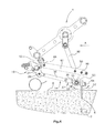
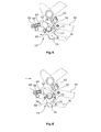
- the protective device 18 is in the FIGS. 5 and 6 shown in more detail.
- the return device 14 coupled to the at least one piercing tool 6 is coupled to the protective device 18 via a second pivot joint 26.
- the illustrated protective device 18 has at least a first pivot arm 24 and a spring device 22, wherein the first pivot arm 24 is pivotable against the spring force of the spring device 22 in the third pivot direction 60. In this case, the first pivot arm 24 pivots about the pivot axis 28.
- the spring 66 of the spring device 22 is arranged on a bolt 64. The bolt 64 is moved due to the pivoting movement of the pivot arm 24, which extends on both sides of the pivot axis 28 and is coupled to the bolt 64. Characterized the element 68 is moved in the direction of the element 62, whereby the spring 66 is compressed.
- the return device 14 is coupled via the second pivot joint 26 with the pivot arm 24.
- the piercing tool 6 strikes a hard object 7 and the piercing tool 6 is already in the starting position, For example, the piercing tool 6 can be moved beyond the starting position in the direction of the second pivoting direction 16. As a result, the return device 14 and thus the pivot joint 26 is moved. The return device 14 and the pivot joint 26 thereby pivot the first pivot arm 24 in the direction of the third pivot direction 60. The pivot arm 24 is pivoted against the spring force of the spring 66 of the spring device 22. In this way, the piercing tool 6, the hard object, such as in the stone 7, dodge and damage to the tillage device 1 can be avoided.
- the spring force of the spring device 22 of the protective device 18 is selected such that the protective device 18 only allows the movement of the piercing tool 6 beyond the starting position when a force is exerted on the piercing tool which exceeds a predetermined force.
- a predetermined force occurs only when the piercing tool 6 on a hard object in the bottom 8, such as a stone 7, occurs.
- the predetermined force is determined by means of several test trials with different substrates.
- the first pivot arm 24 is again due to the spring force of the spring 66 of the spring device 22 in a third pivot direction 60 opposite fourth pivot direction 70 moves back to a part of the pivot arm 24 at a safety device stop 30 stops, which limits the movement in the fourth pivoting direction 70.
- the guard stop 30 is disposed on the member 62. When the pivot arm 24 is already resting against the guard stop 30, the first pivot arm 24 can not be pivoted further in the direction of the fourth pivot direction due to the stop 30.
- FIG. 7 which is a rear view of the soil working device 1, it can be seen that a plurality of tool holders 52 are arranged side by side, to each of which a plurality of piercing tools 6 are attached.
- a return device 14 is coupled to a respective tool holder 52, wherein the return device 14 is in each case coupled to a protective device 18.
- the damage to a cultivating device 1 due to the impact of the pricking tools 6 on a hard object in the bottom 8 can be avoided. It can only occur by the impact of small damage to the piercing tool 6. However, these piercing tools 6 can be easily replaced.
Landscapes
- Life Sciences & Earth Sciences (AREA)
- Engineering & Computer Science (AREA)
- Mechanical Engineering (AREA)
- Soil Sciences (AREA)
- Environmental Sciences (AREA)
- Agricultural Machines (AREA)
- Soil Working Implements (AREA)
Priority Applications (7)
| Application Number | Priority Date | Filing Date | Title |
|---|---|---|---|
| HUE13151318A HUE035383T2 (en) | 2013-01-15 | 2013-01-15 | Walking machine with walk-through protection |
| PL13151318T PL2754343T3 (pl) | 2013-01-15 | 2013-01-15 | Mobilne urządzenie do uprawy gleby z urządzeniem ochronnym |
| EP13151318.6A EP2754343B1 (fr) | 2013-01-15 | 2013-01-15 | Dispositif de traitement de sol mobile avec dispositif de protection |
| DK13151318.6T DK2754343T3 (da) | 2013-01-15 | 2013-01-15 | Mobil jordbearbejdningsindretning med beskyttelsesindretning |
| PCT/EP2014/050683 WO2014111414A1 (fr) | 2013-01-15 | 2014-01-15 | Dispositif mobile de travail du sol, comportant un organe de protection |
| CA2897765A CA2897765C (fr) | 2013-01-15 | 2014-01-15 | Dispositif mobile de travail du sol, comportant un organe de protection |
| US14/760,941 US10070572B2 (en) | 2013-01-15 | 2014-01-15 | Mobile soil-working device with protective means |
Applications Claiming Priority (1)
| Application Number | Priority Date | Filing Date | Title |
|---|---|---|---|
| EP13151318.6A EP2754343B1 (fr) | 2013-01-15 | 2013-01-15 | Dispositif de traitement de sol mobile avec dispositif de protection |
Publications (2)
| Publication Number | Publication Date |
|---|---|
| EP2754343A1 true EP2754343A1 (fr) | 2014-07-16 |
| EP2754343B1 EP2754343B1 (fr) | 2017-11-01 |
Family
ID=47559307
Family Applications (1)
| Application Number | Title | Priority Date | Filing Date |
|---|---|---|---|
| EP13151318.6A Active EP2754343B1 (fr) | 2013-01-15 | 2013-01-15 | Dispositif de traitement de sol mobile avec dispositif de protection |
Country Status (7)
| Country | Link |
|---|---|
| US (1) | US10070572B2 (fr) |
| EP (1) | EP2754343B1 (fr) |
| CA (1) | CA2897765C (fr) |
| DK (1) | DK2754343T3 (fr) |
| HU (1) | HUE035383T2 (fr) |
| PL (1) | PL2754343T3 (fr) |
| WO (1) | WO2014111414A1 (fr) |
Cited By (1)
| Publication number | Priority date | Publication date | Assignee | Title |
|---|---|---|---|---|
| EP3269226A1 (fr) * | 2016-07-13 | 2018-01-17 | SOFT CONTROL GmbH Automatisierungstechnik | Véhicule de cueillette d'asperges en roulant |
Families Citing this family (3)
| Publication number | Priority date | Publication date | Assignee | Title |
|---|---|---|---|---|
| EP2745665B1 (fr) * | 2012-12-21 | 2020-04-22 | Redexim Handel-en Exploitatie Maatschappij B.V. | Dispositif de traitement de sol destiné à travailler les surfaces de sol ainsi que procédé de traitement de surfaces de sol |
| US10130024B2 (en) * | 2017-01-23 | 2018-11-20 | Schiller Grounds Care, Inc. | Tine depth stop mechanism for self-propelled, stand-on aerator |
| US10180179B2 (en) | 2017-01-23 | 2019-01-15 | Schiller Grounds Care, Inc. | Chain tension control mechanism |
Citations (4)
| Publication number | Priority date | Publication date | Assignee | Title |
|---|---|---|---|---|
| EP0037595A1 (fr) * | 1980-03-10 | 1981-10-14 | Redexim Holding S.A. | Appareil pour la confection de drains verticaux dans des pelouses, des champs, des prairies etc. |
| EP0853869A1 (fr) * | 1997-01-03 | 1998-07-22 | REDEXIM Handel- en Exploitatiemaatschappij B.V. | Aérateur de surface |
| DE102005021025A1 (de) * | 2005-04-01 | 2006-10-05 | Wiedenmann Gmbh | Bodenbearbeitungsgerät |
| EP2106679A1 (fr) * | 2008-04-01 | 2009-10-07 | Redexim Handel-en Exploitatie Maatschappij B.V. | Dispositif d'aération au sol |
Family Cites Families (22)
| Publication number | Priority date | Publication date | Assignee | Title |
|---|---|---|---|---|
| US3136274A (en) * | 1960-09-12 | 1964-06-09 | Kriken Machine Mfg Company | Lawn perforator |
| US3797577A (en) * | 1972-06-13 | 1974-03-19 | R Williams | Turf perforating tool |
| US4753298A (en) * | 1985-01-16 | 1988-06-28 | Outboard Marine Corporation | Turf aerating apparatus |
| US4926947A (en) * | 1987-11-16 | 1990-05-22 | Cozine Mark L | Turf aerating apparatus with resilient handle mount |
| US5398767A (en) * | 1988-06-22 | 1995-03-21 | Warke; William L. | Ground treatment apparatus |
| DE3937211A1 (de) * | 1989-11-08 | 1991-05-16 | Wiedenmann Gmbh | Bearbeitungsgeraet fuer die tiefenlockerung der boeden |
| US5570746A (en) * | 1993-03-15 | 1996-11-05 | Southern Green, Inc. | Turf aeration device |
| US5469922A (en) * | 1993-08-23 | 1995-11-28 | Bjorge; Scott W. | Soil aerator |
| IT1285464B1 (it) * | 1996-02-22 | 1998-06-08 | Franco Selvatici | Apparecchiatura per il trattamento del terreno |
| DE19655123C2 (de) * | 1996-07-31 | 2000-03-09 | Wiedenmann Gmbh | Bearbeitungsgerät für die Tiefenlockerung von Böden |
| US20020189825A1 (en) * | 1999-12-23 | 2002-12-19 | Livingstone David John | Reciprocating drive mechanism for a turf aerator |
| US20050178567A1 (en) * | 2002-05-15 | 2005-08-18 | Wiedenmann Gmbh | Soil cultivating device |
| US7267181B2 (en) * | 2002-08-15 | 2007-09-11 | Deere & Company | Cultivating device |
| NL1031566C2 (nl) * | 2006-04-11 | 2007-10-12 | Redexim Handel En Expl Mij Bv | Beluchtingsinrichting. |
| EP2120526B8 (fr) * | 2007-02-22 | 2012-03-14 | Greencare Industries Pty Ltd | Mécanisme d'aérateur avec dent à mouvement alternatif vertical |
| EP1967055A1 (fr) * | 2007-03-06 | 2008-09-10 | Redexim Handel-en Exploitatie Maatschappij B.V. | Dispositif de traitement de sol |
| US20080257571A1 (en) * | 2007-03-13 | 2008-10-23 | William Anthony Keane | Frame Orientation Control Device for an Aeration Apparatus |
| EP2014146B2 (fr) * | 2007-07-12 | 2016-03-02 | Redexim Handel-en Exploitatie Maatschappij B.V. | Dispositif de traitement de sol |
| DE102008017242B4 (de) * | 2008-03-10 | 2011-12-22 | Wiedenmann Gmbh | Bodenbearbeitungsgerät |
| EP2106680A1 (fr) * | 2008-04-01 | 2009-10-07 | Redexim Handel-en Exploitatie Maatschappij B.V. | Dispositif d'aération au sol |
| EP2123143B1 (fr) * | 2008-05-23 | 2013-11-06 | Redexim Handel-en Exploitatie Maatschappij B.V. | Dispositif d'aération du sol et procédé pour enfoncer des outils de pénétration dans le sol |
| US8925643B2 (en) * | 2012-03-30 | 2015-01-06 | Deere & Company | Aerator with coring depth adjustment |
-
2013
- 2013-01-15 DK DK13151318.6T patent/DK2754343T3/da active
- 2013-01-15 PL PL13151318T patent/PL2754343T3/pl unknown
- 2013-01-15 EP EP13151318.6A patent/EP2754343B1/fr active Active
- 2013-01-15 HU HUE13151318A patent/HUE035383T2/en unknown
-
2014
- 2014-01-15 US US14/760,941 patent/US10070572B2/en active Active
- 2014-01-15 CA CA2897765A patent/CA2897765C/fr active Active
- 2014-01-15 WO PCT/EP2014/050683 patent/WO2014111414A1/fr active Application Filing
Patent Citations (4)
| Publication number | Priority date | Publication date | Assignee | Title |
|---|---|---|---|---|
| EP0037595A1 (fr) * | 1980-03-10 | 1981-10-14 | Redexim Holding S.A. | Appareil pour la confection de drains verticaux dans des pelouses, des champs, des prairies etc. |
| EP0853869A1 (fr) * | 1997-01-03 | 1998-07-22 | REDEXIM Handel- en Exploitatiemaatschappij B.V. | Aérateur de surface |
| DE102005021025A1 (de) * | 2005-04-01 | 2006-10-05 | Wiedenmann Gmbh | Bodenbearbeitungsgerät |
| EP2106679A1 (fr) * | 2008-04-01 | 2009-10-07 | Redexim Handel-en Exploitatie Maatschappij B.V. | Dispositif d'aération au sol |
Cited By (1)
| Publication number | Priority date | Publication date | Assignee | Title |
|---|---|---|---|---|
| EP3269226A1 (fr) * | 2016-07-13 | 2018-01-17 | SOFT CONTROL GmbH Automatisierungstechnik | Véhicule de cueillette d'asperges en roulant |
Also Published As
| Publication number | Publication date |
|---|---|
| CA2897765C (fr) | 2019-06-25 |
| PL2754343T3 (pl) | 2018-05-30 |
| WO2014111414A1 (fr) | 2014-07-24 |
| CA2897765A1 (fr) | 2014-07-24 |
| EP2754343B1 (fr) | 2017-11-01 |
| US20150342109A1 (en) | 2015-12-03 |
| US10070572B2 (en) | 2018-09-11 |
| DK2754343T3 (da) | 2018-01-29 |
| HUE035383T2 (en) | 2018-05-02 |
Similar Documents
| Publication | Publication Date | Title |
|---|---|---|
| EP1951024B1 (fr) | Appareil de traitement du sol dote d'une protection de manivelle | |
| EP0924975B1 (fr) | Outil pour ameublir le sol en profondeur | |
| DE2139380B2 (fr) | ||
| EP1967055A1 (fr) | Dispositif de traitement de sol | |
| EP2745665B1 (fr) | Dispositif de traitement de sol destiné à travailler les surfaces de sol ainsi que procédé de traitement de surfaces de sol | |
| EP2754343B1 (fr) | Dispositif de traitement de sol mobile avec dispositif de protection | |
| EP0452449B1 (fr) | Instrument de sous-solage | |
| DE2637899C3 (de) | Schleppkopfsaugbagger | |
| EP2944167B1 (fr) | Dispositif de traitement de sol | |
| EP2914083B1 (fr) | Dispositif de travail du sol pour réaliser des cavités dans un sol | |
| EP1856965B1 (fr) | Charrue réversible avec dispositif de sécurité contre la surcharge | |
| DE3106660C2 (de) | Bodenbearbeitungsgerät im wesentlichen in Art einer Scheibenegge oder dergleichen | |
| EP3616495B1 (fr) | Mécanisme de fixation pour un dispositif de broyage / de coupe pour matière végétale sur un véhicule, en particulier un tracteur ou analogue | |
| DE19630961C2 (de) | Bearbeitungsgerät für die Tiefenlockerung von Böden | |
| EP2997803B1 (fr) | Outillage agricole | |
| DE2538883A1 (de) | Drehpflug | |
| DE19602130A1 (de) | Verbesserte Egge | |
| EP3545736B1 (fr) | Machine de travail du sol | |
| AT506569B1 (de) | Vorrichtung zur anbringung von arbeitsgeräten | |
| DE948564C (de) | Mehrgelenk-Anbauvorrichtung fuer den an Schleppern oder Zugmaschinen verstellbar angelenkten Tragrahmen von Bodenbearbeitungsgeraeten | |
| EP4173457A1 (fr) | Agencement doté d'un outil de travail destiné au traitement du sol pour une machine agricole, ainsi que machine agricole | |
| DE8135323U1 (de) | Drehpflug mit einer rahmenschwenkeinrichtung | |
| DE7734436U1 (de) | Bodenbearbeitungsgerät, insbesondere Kreiselegge | |
| DE2910621A1 (de) | Federnde aufhaengevorrichtung von grubberzinken oder aehnlichen arbeitswerkzeugen landwirtschaftlicher bodenbearbeitungsgeraete | |
| DE2420897C3 (de) | Vorrichtung zum maschinellen Beschneiden von Rebstöcken in Weingärten, die am Spalier befestigt sind |
Legal Events
| Date | Code | Title | Description |
|---|---|---|---|
| PUAI | Public reference made under article 153(3) epc to a published international application that has entered the european phase |
Free format text: ORIGINAL CODE: 0009012 |
|
| 17P | Request for examination filed |
Effective date: 20130115 |
|
| AK | Designated contracting states |
Kind code of ref document: A1 Designated state(s): AL AT BE BG CH CY CZ DE DK EE ES FI FR GB GR HR HU IE IS IT LI LT LU LV MC MK MT NL NO PL PT RO RS SE SI SK SM TR |
|
| AX | Request for extension of the european patent |
Extension state: BA ME |
|
| R17P | Request for examination filed (corrected) |
Effective date: 20150116 |
|
| RBV | Designated contracting states (corrected) |
Designated state(s): AL AT BE BG CH CY CZ DE DK EE ES FI FR GB GR HR HU IE IS IT LI LT LU LV MC MK MT NL NO PL PT RO RS SE SI SK SM TR |
|
| GRAP | Despatch of communication of intention to grant a patent |
Free format text: ORIGINAL CODE: EPIDOSNIGR1 |
|
| INTG | Intention to grant announced |
Effective date: 20170529 |
|
| RIN1 | Information on inventor provided before grant (corrected) |
Inventor name: DE BREE, CORNELIUS HERMANUS MARIA |
|
| GRAS | Grant fee paid |
Free format text: ORIGINAL CODE: EPIDOSNIGR3 |
|
| GRAA | (expected) grant |
Free format text: ORIGINAL CODE: 0009210 |
|
| AK | Designated contracting states |
Kind code of ref document: B1 Designated state(s): AL AT BE BG CH CY CZ DE DK EE ES FI FR GB GR HR HU IE IS IT LI LT LU LV MC MK MT NL NO PL PT RO RS SE SI SK SM TR |
|
| REG | Reference to a national code |
Ref country code: GB Ref legal event code: FG4D Free format text: NOT ENGLISH |
|
| REG | Reference to a national code |
Ref country code: CH Ref legal event code: EP Ref country code: AT Ref legal event code: REF Ref document number: 941057 Country of ref document: AT Kind code of ref document: T Effective date: 20171115 |
|
| REG | Reference to a national code |
Ref country code: IE Ref legal event code: FG4D Free format text: LANGUAGE OF EP DOCUMENT: GERMAN |
|
| REG | Reference to a national code |
Ref country code: DE Ref legal event code: R096 Ref document number: 502013008686 Country of ref document: DE |
|
| REG | Reference to a national code |
Ref country code: DK Ref legal event code: T3 Effective date: 20180125 |
|
| REG | Reference to a national code |
Ref country code: FR Ref legal event code: PLFP Year of fee payment: 6 |
|
| REG | Reference to a national code |
Ref country code: CH Ref legal event code: NV Representative=s name: ISLER AND PEDRAZZINI AG, CH |
|
| REG | Reference to a national code |
Ref country code: NL Ref legal event code: FP |
|
| REG | Reference to a national code |
Ref country code: SE Ref legal event code: TRGR |
|
| PGFP | Annual fee paid to national office [announced via postgrant information from national office to epo] |
Ref country code: LU Payment date: 20180119 Year of fee payment: 6 |
|
| REG | Reference to a national code |
Ref country code: LT Ref legal event code: MG4D |
|
| PG25 | Lapsed in a contracting state [announced via postgrant information from national office to epo] |
Ref country code: ES Free format text: LAPSE BECAUSE OF FAILURE TO SUBMIT A TRANSLATION OF THE DESCRIPTION OR TO PAY THE FEE WITHIN THE PRESCRIBED TIME-LIMIT Effective date: 20171101 Ref country code: NO Free format text: LAPSE BECAUSE OF FAILURE TO SUBMIT A TRANSLATION OF THE DESCRIPTION OR TO PAY THE FEE WITHIN THE PRESCRIBED TIME-LIMIT Effective date: 20180201 Ref country code: LT Free format text: LAPSE BECAUSE OF FAILURE TO SUBMIT A TRANSLATION OF THE DESCRIPTION OR TO PAY THE FEE WITHIN THE PRESCRIBED TIME-LIMIT Effective date: 20171101 |
|
| PGFP | Annual fee paid to national office [announced via postgrant information from national office to epo] |
Ref country code: FI Payment date: 20180124 Year of fee payment: 6 Ref country code: DK Payment date: 20180131 Year of fee payment: 6 Ref country code: CH Payment date: 20180111 Year of fee payment: 6 |
|
| REG | Reference to a national code |
Ref country code: HU Ref legal event code: AG4A Ref document number: E035383 Country of ref document: HU |
|
| PG25 | Lapsed in a contracting state [announced via postgrant information from national office to epo] |
Ref country code: RS Free format text: LAPSE BECAUSE OF FAILURE TO SUBMIT A TRANSLATION OF THE DESCRIPTION OR TO PAY THE FEE WITHIN THE PRESCRIBED TIME-LIMIT Effective date: 20171101 Ref country code: LV Free format text: LAPSE BECAUSE OF FAILURE TO SUBMIT A TRANSLATION OF THE DESCRIPTION OR TO PAY THE FEE WITHIN THE PRESCRIBED TIME-LIMIT Effective date: 20171101 Ref country code: IS Free format text: LAPSE BECAUSE OF FAILURE TO SUBMIT A TRANSLATION OF THE DESCRIPTION OR TO PAY THE FEE WITHIN THE PRESCRIBED TIME-LIMIT Effective date: 20180301 Ref country code: GR Free format text: LAPSE BECAUSE OF FAILURE TO SUBMIT A TRANSLATION OF THE DESCRIPTION OR TO PAY THE FEE WITHIN THE PRESCRIBED TIME-LIMIT Effective date: 20180202 Ref country code: BG Free format text: LAPSE BECAUSE OF FAILURE TO SUBMIT A TRANSLATION OF THE DESCRIPTION OR TO PAY THE FEE WITHIN THE PRESCRIBED TIME-LIMIT Effective date: 20180201 Ref country code: HR Free format text: LAPSE BECAUSE OF FAILURE TO SUBMIT A TRANSLATION OF THE DESCRIPTION OR TO PAY THE FEE WITHIN THE PRESCRIBED TIME-LIMIT Effective date: 20171101 |
|
| PGFP | Annual fee paid to national office [announced via postgrant information from national office to epo] |
Ref country code: AT Payment date: 20180119 Year of fee payment: 6 Ref country code: SE Payment date: 20180126 Year of fee payment: 6 Ref country code: IE Payment date: 20180105 Year of fee payment: 6 Ref country code: PL Payment date: 20180112 Year of fee payment: 6 |
|
| PG25 | Lapsed in a contracting state [announced via postgrant information from national office to epo] |
Ref country code: SK Free format text: LAPSE BECAUSE OF FAILURE TO SUBMIT A TRANSLATION OF THE DESCRIPTION OR TO PAY THE FEE WITHIN THE PRESCRIBED TIME-LIMIT Effective date: 20171101 Ref country code: EE Free format text: LAPSE BECAUSE OF FAILURE TO SUBMIT A TRANSLATION OF THE DESCRIPTION OR TO PAY THE FEE WITHIN THE PRESCRIBED TIME-LIMIT Effective date: 20171101 Ref country code: CY Free format text: LAPSE BECAUSE OF FAILURE TO SUBMIT A TRANSLATION OF THE DESCRIPTION OR TO PAY THE FEE WITHIN THE PRESCRIBED TIME-LIMIT Effective date: 20171101 Ref country code: CZ Free format text: LAPSE BECAUSE OF FAILURE TO SUBMIT A TRANSLATION OF THE DESCRIPTION OR TO PAY THE FEE WITHIN THE PRESCRIBED TIME-LIMIT Effective date: 20171101 |
|
| REG | Reference to a national code |
Ref country code: DE Ref legal event code: R097 Ref document number: 502013008686 Country of ref document: DE |
|
| PG25 | Lapsed in a contracting state [announced via postgrant information from national office to epo] |
Ref country code: SM Free format text: LAPSE BECAUSE OF FAILURE TO SUBMIT A TRANSLATION OF THE DESCRIPTION OR TO PAY THE FEE WITHIN THE PRESCRIBED TIME-LIMIT Effective date: 20171101 Ref country code: RO Free format text: LAPSE BECAUSE OF FAILURE TO SUBMIT A TRANSLATION OF THE DESCRIPTION OR TO PAY THE FEE WITHIN THE PRESCRIBED TIME-LIMIT Effective date: 20171101 |
|
| PLBE | No opposition filed within time limit |
Free format text: ORIGINAL CODE: 0009261 |
|
| STAA | Information on the status of an ep patent application or granted ep patent |
Free format text: STATUS: NO OPPOSITION FILED WITHIN TIME LIMIT |
|
| PG25 | Lapsed in a contracting state [announced via postgrant information from national office to epo] |
Ref country code: MT Free format text: LAPSE BECAUSE OF FAILURE TO SUBMIT A TRANSLATION OF THE DESCRIPTION OR TO PAY THE FEE WITHIN THE PRESCRIBED TIME-LIMIT Effective date: 20171101 |
|
| 26N | No opposition filed |
Effective date: 20180802 |
|
| REG | Reference to a national code |
Ref country code: BE Ref legal event code: MM Effective date: 20180131 |
|
| PG25 | Lapsed in a contracting state [announced via postgrant information from national office to epo] |
Ref country code: SI Free format text: LAPSE BECAUSE OF FAILURE TO SUBMIT A TRANSLATION OF THE DESCRIPTION OR TO PAY THE FEE WITHIN THE PRESCRIBED TIME-LIMIT Effective date: 20171101 Ref country code: BE Free format text: LAPSE BECAUSE OF NON-PAYMENT OF DUE FEES Effective date: 20180131 |
|
| PG25 | Lapsed in a contracting state [announced via postgrant information from national office to epo] |
Ref country code: MC Free format text: LAPSE BECAUSE OF FAILURE TO SUBMIT A TRANSLATION OF THE DESCRIPTION OR TO PAY THE FEE WITHIN THE PRESCRIBED TIME-LIMIT Effective date: 20171101 |
|
| REG | Reference to a national code |
Ref country code: DK Ref legal event code: EBP Effective date: 20190131 |
|
| REG | Reference to a national code |
Ref country code: CH Ref legal event code: PL |
|
| REG | Reference to a national code |
Ref country code: AT Ref legal event code: MM01 Ref document number: 941057 Country of ref document: AT Kind code of ref document: T Effective date: 20190115 |
|
| PG25 | Lapsed in a contracting state [announced via postgrant information from national office to epo] |
Ref country code: LU Free format text: LAPSE BECAUSE OF NON-PAYMENT OF DUE FEES Effective date: 20190115 |
|
| REG | Reference to a national code |
Ref country code: IE Ref legal event code: MM4A |
|
| PG25 | Lapsed in a contracting state [announced via postgrant information from national office to epo] |
Ref country code: SE Free format text: LAPSE BECAUSE OF NON-PAYMENT OF DUE FEES Effective date: 20190116 Ref country code: FI Free format text: LAPSE BECAUSE OF NON-PAYMENT OF DUE FEES Effective date: 20190115 |
|
| PG25 | Lapsed in a contracting state [announced via postgrant information from national office to epo] |
Ref country code: CH Free format text: LAPSE BECAUSE OF NON-PAYMENT OF DUE FEES Effective date: 20190131 Ref country code: LI Free format text: LAPSE BECAUSE OF NON-PAYMENT OF DUE FEES Effective date: 20190131 Ref country code: AT Free format text: LAPSE BECAUSE OF NON-PAYMENT OF DUE FEES Effective date: 20190115 |
|
| PG25 | Lapsed in a contracting state [announced via postgrant information from national office to epo] |
Ref country code: IE Free format text: LAPSE BECAUSE OF NON-PAYMENT OF DUE FEES Effective date: 20190115 Ref country code: DK Free format text: LAPSE BECAUSE OF NON-PAYMENT OF DUE FEES Effective date: 20190131 |
|
| PG25 | Lapsed in a contracting state [announced via postgrant information from national office to epo] |
Ref country code: TR Free format text: LAPSE BECAUSE OF FAILURE TO SUBMIT A TRANSLATION OF THE DESCRIPTION OR TO PAY THE FEE WITHIN THE PRESCRIBED TIME-LIMIT Effective date: 20171101 |
|
| PG25 | Lapsed in a contracting state [announced via postgrant information from national office to epo] |
Ref country code: PT Free format text: LAPSE BECAUSE OF FAILURE TO SUBMIT A TRANSLATION OF THE DESCRIPTION OR TO PAY THE FEE WITHIN THE PRESCRIBED TIME-LIMIT Effective date: 20171101 |
|
| PG25 | Lapsed in a contracting state [announced via postgrant information from national office to epo] |
Ref country code: MK Free format text: LAPSE BECAUSE OF NON-PAYMENT OF DUE FEES Effective date: 20171101 |
|
| PG25 | Lapsed in a contracting state [announced via postgrant information from national office to epo] |
Ref country code: AL Free format text: LAPSE BECAUSE OF FAILURE TO SUBMIT A TRANSLATION OF THE DESCRIPTION OR TO PAY THE FEE WITHIN THE PRESCRIBED TIME-LIMIT Effective date: 20171101 |
|
| PG25 | Lapsed in a contracting state [announced via postgrant information from national office to epo] |
Ref country code: PL Free format text: LAPSE BECAUSE OF NON-PAYMENT OF DUE FEES Effective date: 20190115 |
|
| P01 | Opt-out of the competence of the unified patent court (upc) registered |
Effective date: 20230530 |
|
| PGFP | Annual fee paid to national office [announced via postgrant information from national office to epo] |
Ref country code: NL Payment date: 20240327 Year of fee payment: 12 |
|
| PGFP | Annual fee paid to national office [announced via postgrant information from national office to epo] |
Ref country code: DE Payment date: 20240320 Year of fee payment: 12 Ref country code: GB Payment date: 20240327 Year of fee payment: 12 |
|
| PGFP | Annual fee paid to national office [announced via postgrant information from national office to epo] |
Ref country code: IT Payment date: 20240322 Year of fee payment: 12 Ref country code: FR Payment date: 20240327 Year of fee payment: 12 |
|
| PGFP | Annual fee paid to national office [announced via postgrant information from national office to epo] |
Ref country code: HU Payment date: 20240410 Year of fee payment: 12 |