EP2754343A1 - Mobile soil cultivation device with protective device - Google Patents
Mobile soil cultivation device with protective device Download PDFInfo
- Publication number
- EP2754343A1 EP2754343A1 EP13151318.6A EP13151318A EP2754343A1 EP 2754343 A1 EP2754343 A1 EP 2754343A1 EP 13151318 A EP13151318 A EP 13151318A EP 2754343 A1 EP2754343 A1 EP 2754343A1
- Authority
- EP
- European Patent Office
- Prior art keywords
- piercing
- pivoting
- piercing tool
- tool
- pivot
- Prior art date
- Legal status (The legal status is an assumption and is not a legal conclusion. Google has not performed a legal analysis and makes no representation as to the accuracy of the status listed.)
- Granted
Links
- 230000001681 protective effect Effects 0.000 title claims abstract description 38
- 239000002689 soil Substances 0.000 title claims abstract description 31
- 238000000034 method Methods 0.000 claims abstract description 8
- 238000003971 tillage Methods 0.000 claims description 11
- 238000003780 insertion Methods 0.000 abstract 1
- 230000037431 insertion Effects 0.000 abstract 1
- 230000035515 penetration Effects 0.000 abstract 1
- 239000004575 stone Substances 0.000 description 5
- 238000013016 damping Methods 0.000 description 3
- 230000006835 compression Effects 0.000 description 1
- 238000007906 compression Methods 0.000 description 1
- 230000008878 coupling Effects 0.000 description 1
- 238000010168 coupling process Methods 0.000 description 1
- 238000005859 coupling reaction Methods 0.000 description 1
- 230000003116 impacting effect Effects 0.000 description 1
- 230000000284 resting effect Effects 0.000 description 1
- 239000000758 substrate Substances 0.000 description 1
Images


Classifications
-
- A—HUMAN NECESSITIES
- A01—AGRICULTURE; FORESTRY; ANIMAL HUSBANDRY; HUNTING; TRAPPING; FISHING
- A01B—SOIL WORKING IN AGRICULTURE OR FORESTRY; PARTS, DETAILS, OR ACCESSORIES OF AGRICULTURAL MACHINES OR IMPLEMENTS, IN GENERAL
- A01B45/00—Machines for treating meadows or lawns, e.g. for sports grounds
- A01B45/02—Machines for treating meadows or lawns, e.g. for sports grounds for aerating
- A01B45/023—Perforators comprising spiking tools actively driven in a reciprocating movement through a crankshaft or eccentric mechanism
Definitions
- the invention relates to a mobile soil cultivation device according to the preamble of claim 1 and to a method for processing a soil according to the preamble of claim 12.
- tillage devices which have at least one machine frame, a drive for at least one upwardly and downwardly movable piercing tool, wherein the piercing tool can be pierced into the ground and pulled out again.
- the piercing tool is located prior to piercing into the ground in a starting position at a predetermined piercing angle and performs in the ground due to the movement of the machine frame in the direction of travel an up and down motion superimposed pivotal movement about a first pivot axis in the direction of a first pivoting direction.
- coupled to the piercing tool return means is provided, which transfers the piercing tool after exiting the ground back into the starting position by pivoting the piercing tool in one of the first pivot direction opposite second pivot direction.
- a tilling device which has two parallelogrammartig guided support arms, which pivotally hold a tool holder at one end and which are pivotally mounted on a machine frame at the other end.
- a push rod of a ball drive is articulated to the tool holder and drives it, so that it performs an up and down movement.
- One of the two support arms is variable in length and includes a stop spring device. As soon as the piercing tool is outside the ground, the support arm is pulled against the stop due to the spring force. When punctured piercing tool and forward movement of the tillage device pivots the tool with the tool holder counter to the direction of travel and the variable length support arm is extended against the spring force.
- the invention provides in an advantageous manner that the return device is coupled to a protective device that allows pivoting of the piercing tool in the second pivoting direction beyond the initial position, so that the piercing tool when hitting a hard object in the ground by pivoting the piercing tool into the second Swivel direction beyond the initial position is also pivotable.
- the piercing tool can also avoid the object in the direction of the second pivoting direction, although the piercing tool is already in the starting position. By avoiding the piercing tool, there is no serious damage to the machine or the piercing tool.
- the coupled to the at least one piercing tool return device may be coupled via a second pivot joint with the protective device.
- the return device can be coupled via a third pivot joint with the piercing tool.
- the return device is preferably arranged between the piercing tool and the protective device.
- the protective device may comprise at least a first pivot arm and a spring device, wherein the first pivot arm is pivotable against the spring force of the spring device in a third pivot direction, wherein the return device is coupled via the second pivot joint with the first pivot arm of the protection device.
- the second pivot joint of the retracting device can be movable, so that the first pivoting arm of the protective device coupled to the second pivoting joint can be dispensed counter to the spring force of the spring device of the protective device in a third pivoting direction.
- the spring force of the spring device of the protective device may be selected such that the protective device only allows the movement of the piercing tool beyond the initial position when a force is exerted on the piercing tool which exceeds a predetermined force.
- the piercing tool can be first moved beyond the starting position when a high force is exerted on the piercing tool, as happens for example when hitting a hard object in the ground.
- At least one tool holder for the at least one piercing tool can be provided, which is mounted about the first pivot axis in the guide arm which can be moved up and down by the drive.
- a return device is coupled to a respective tool holder, wherein the return devices are each coupled to a protective device.
- the first pivot arm of the protective device can be pivoted against the spring force of the spring device in the third pivot direction, wherein a protective device stop is provided which limits the pivoting of the first pivot arm in the third pivot direction opposite fourth pivot direction.
- the piercing tool is pivoted on impacting a hard object in the ground by pivoting the piercing tool in the second pivoting direction beyond the initial position.
- the piercing tool can be pivoted beyond the initial position when a force is exerted on the piercing tool that exceeds a predetermined force.
- Fig. 1 shows a tillage device 1 in side view.
- the soil cultivation device 1 has a coupling device 40, with which the Soil cultivation device 1 can be coupled to a towing vehicle and can be pulled with the towing vehicle.
- the tillage device 1 could also be self-propelled.
- the soil cultivation device 1 has a machine frame 42. Furthermore, the soil cultivating device 1 has a drive 4 for at least one pierceable tool 6 which can be moved up and down. In the present embodiment, a plurality of piercing tools 6 are provided. The piercing tools 6 can be pierced into the ground and pulled out again. The piercing tools 6 are located prior to piercing the soil 8 in a starting position at a predetermined piercing angle and lead in the ground 8 due to the movement of the machine frame 42 in the direction of travel A up and down motion superimposed pivotal movement about a first pivot axis 10 in the direction of a first Pivoting direction 12 off.
- FIG. 2 is shown schematically the side view of a drive 4 for a movable up and down lancing tool 6.
- a guide arm 44 is pivotally mounted about an axis 46.
- the guide arm 44 is coupled to the drive 4, which is a crank drive, via the push rod 48 articulated via the hinge 50.
- the guide space 44 is driven by the drive 4 via the push rod 48.
- the guide arm 44 is moved up and down due to the drive 4.
- a tool holder 52 is mounted about a first pivot axis 10. At least one piercing tool 6 is fastened to the tool holder 52 via a fastening device 54. There are preferably a plurality of piercing tools 6 attached to the tool holder 52. In the illustrated embodiment, three piercing tools 6 are attached to the tool holder 52. Due to the movement of the machine frame 42 in the direction of travel A, the at least one piercing tool 6 executes a pivoting movement superimposed on the up and down movement about the first pivot axis 10 in the direction of the first pivoting direction 12.
- a return device 14 is coupled to the tool holder 52 via the hinge 11.
- the illustrated return device is preferably arranged parallelogram next to the guide space 44.
- the illustrated return device 14 is preferably a piston-cylinder unit.
- the return device 14 has the piston element 34, which is a piston rod on.
- the return device 14 has the cylinder element 36.
- a compression spring not shown, is arranged in the cylinder member 36.
- the return device 14 is coupled at the opposite end of the hinge 11 via a second pivot joint 26 with a guard 18.
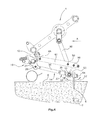
- the protective device 18 is related to the FIGS. 5 and 6 explained in more detail.
- FIG. 2 a state is shown in which the piercing tool 6 is pivoted in the direction of the first pivoting direction 12. How out FIG. 2 can be seen, the piston member 34 is pulled out of the cylinder member 36. On the cylinder element 36, a stop 33 is arranged, which has a damping device 32. Furthermore, the piston element 34 has a flange 35.
- FIG. 3 a state is shown in which the piercing tool 6 has already been pulled out of the ground and has already been pivoted by the return device 14 back to the starting position.
- the stop 33 limits the pivoting of the piercing tool 6 is the second pivoting direction 16. In the illustrated embodiment, this is realized in that the flange 35 bears against the damping device 32 of the stopper 33.
- the piercing tool 6 shown is located prior to piercing in the bottom 8 in the starting position at a predetermined piercing angle ⁇ .
- FIG. 4 the piercing tool 6 is again stabbed in the ground. It is in FIG. 4 a state in which the piercing tool 6 on a hard object, which in the present case is a stone 7, impinges. As a result, the piercing tool 6 is pivoted in the direction of the second pivoting direction 16.
- FIG. 4 is shown a state in which the flange 35 is already applied to the damping device 32 of the stop 33.
- the stopper 33 already limits the pivoting of the piercing tool in the second pivoting direction 16 and the piercing tool 6 is in the starting position.
- the present invention advantageously provides that the return device 14 is coupled to a protective device 18.
- This protective device 18 allows pivoting of the piercing tool 6 in the second pivoting direction 16 beyond the initial position, so that the piercing tool 6 when hitting a hard object in the bottom 8, such. B. the stone 7 by pivoting the piercing tool 6 in the second pivoting direction 16 beyond the initial position is also pivotable.
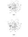
- the protective device 18 is in the FIGS. 5 and 6 shown in more detail.
- the return device 14 coupled to the at least one piercing tool 6 is coupled to the protective device 18 via a second pivot joint 26.
- the illustrated protective device 18 has at least a first pivot arm 24 and a spring device 22, wherein the first pivot arm 24 is pivotable against the spring force of the spring device 22 in the third pivot direction 60. In this case, the first pivot arm 24 pivots about the pivot axis 28.
- the spring 66 of the spring device 22 is arranged on a bolt 64. The bolt 64 is moved due to the pivoting movement of the pivot arm 24, which extends on both sides of the pivot axis 28 and is coupled to the bolt 64. Characterized the element 68 is moved in the direction of the element 62, whereby the spring 66 is compressed.
- the return device 14 is coupled via the second pivot joint 26 with the pivot arm 24.
- the piercing tool 6 strikes a hard object 7 and the piercing tool 6 is already in the starting position, For example, the piercing tool 6 can be moved beyond the starting position in the direction of the second pivoting direction 16. As a result, the return device 14 and thus the pivot joint 26 is moved. The return device 14 and the pivot joint 26 thereby pivot the first pivot arm 24 in the direction of the third pivot direction 60. The pivot arm 24 is pivoted against the spring force of the spring 66 of the spring device 22. In this way, the piercing tool 6, the hard object, such as in the stone 7, dodge and damage to the tillage device 1 can be avoided.
- the spring force of the spring device 22 of the protective device 18 is selected such that the protective device 18 only allows the movement of the piercing tool 6 beyond the starting position when a force is exerted on the piercing tool which exceeds a predetermined force.
- a predetermined force occurs only when the piercing tool 6 on a hard object in the bottom 8, such as a stone 7, occurs.
- the predetermined force is determined by means of several test trials with different substrates.
- the first pivot arm 24 is again due to the spring force of the spring 66 of the spring device 22 in a third pivot direction 60 opposite fourth pivot direction 70 moves back to a part of the pivot arm 24 at a safety device stop 30 stops, which limits the movement in the fourth pivoting direction 70.
- the guard stop 30 is disposed on the member 62. When the pivot arm 24 is already resting against the guard stop 30, the first pivot arm 24 can not be pivoted further in the direction of the fourth pivot direction due to the stop 30.
- FIG. 7 which is a rear view of the soil working device 1, it can be seen that a plurality of tool holders 52 are arranged side by side, to each of which a plurality of piercing tools 6 are attached.
- a return device 14 is coupled to a respective tool holder 52, wherein the return device 14 is in each case coupled to a protective device 18.
- the damage to a cultivating device 1 due to the impact of the pricking tools 6 on a hard object in the bottom 8 can be avoided. It can only occur by the impact of small damage to the piercing tool 6. However, these piercing tools 6 can be easily replaced.
Landscapes
- Life Sciences & Earth Sciences (AREA)
- Engineering & Computer Science (AREA)
- Mechanical Engineering (AREA)
- Soil Sciences (AREA)
- Environmental Sciences (AREA)
- Agricultural Machines (AREA)
- Soil Working Implements (AREA)
Abstract
Description
Die Erfindung betrifft eine fahrbare Bodenbearbeitungsvorrichtung nach dem Oberbegriff des Anspruchs 1 sowie ein Verfahren zum Bearbeiten eines Bodens nach dem Oberbegriff des Anspruchs 12.The invention relates to a mobile soil cultivation device according to the preamble of
Es sind Bodenbearbeitungsvorrichtungen aus dem Stand der Technik bekannt, die mindestens einen Maschinenrahmen, einen Antrieb für mindestens ein auf - und abbewegbares Stechwerkzeug aufweisen, wobei das Stechwerkzeug in den Boden einstechbar und wieder herausziehbar ist. Das Stechwerkzeug befindet sich vor dem Einstechen in den Boden in einer Ausgangslage unter einem vorgegebenen Einstechwinkel und führt im Boden aufgrund der Bewegung des Maschinenrahmens in Fahrtrichtung eine die Auf- und Abbewegung überlagernde Schwenkbewegung um eine erste Schwenkachse in Richtung einer ersten Schwenkrichtung aus. Ferner ist eine mit dem Stechwerkzeug gekoppelte Rückholeinrichtung vorgesehen, die das Stechwerkzeug nach dem Austritt aus dem Boden zurück in die Ausgangslage durch Verschwenken des Stechwerkzeugs in eine der ersten Schwenkrichtung entgegengesetzte zweite Schwenkrichtung überführt.There are known from the prior art tillage devices which have at least one machine frame, a drive for at least one upwardly and downwardly movable piercing tool, wherein the piercing tool can be pierced into the ground and pulled out again. The piercing tool is located prior to piercing into the ground in a starting position at a predetermined piercing angle and performs in the ground due to the movement of the machine frame in the direction of travel an up and down motion superimposed pivotal movement about a first pivot axis in the direction of a first pivoting direction. Further, coupled to the piercing tool return means is provided, which transfers the piercing tool after exiting the ground back into the starting position by pivoting the piercing tool in one of the first pivot direction opposite second pivot direction.
Aus der europäischen Offenlegungsschrift
Bei den bisher bekannten Bodenbearbeitungsvorrichtungen besteht jedoch der Nachteil, dass die Stechwerkzeuge beschädigt werden können, wenn sie in dem Boden auf einen harten Gegenstand, wie beispielsweise einen Stein, auftreffen.In the previously known soil working devices, however, there is the disadvantage that the piercing tools can be damaged when they impinge on the floor on a hard object, such as a stone.
Aufgabe der vorliegenden Erfindung ist es daher, eine Bodenbearbeitungsvorrichtung und ein Verfahren zum Bearbeiten einer Bodenfläche zu schaffen, bei der bzw. bei dem die Bodenbearbeitungsvorrichtung vor Beschädigung geschützt ist, wenn das mindestens eine Stechwerkzeug auf einen harten Gegenstand im Boden trifft.It is therefore an object of the present invention to provide a soil cultivating device and a method for cultivating a soil surface in which the cultivating device is protected from damage when the at least one pricking tool strikes a hard object in the soil.
Zur Lösung dieser Aufgabe dienen die Merkmale der Ansprüche 1 und 12.To achieve this object, the features of
Die Erfindung sieht in vorteilhafterweise vor, dass die Rückholeinrichtung mit einer Schutzeinrichtung gekoppelt ist, die ein Verschwenken des Stechwerkzeugs in die zweite Schwenkrichtung über die Ausgangslage hinaus erlaubt, so dass das Stechwerkzeug beim Auftreffen auf einen harten Gegenstand im Boden durch Verschwenken des Stechwerkzeugs in die zweite Schwenkrichtung über die Ausgangslage hinaus verschwenkbar ist.The invention provides in an advantageous manner that the return device is coupled to a protective device that allows pivoting of the piercing tool in the second pivoting direction beyond the initial position, so that the piercing tool when hitting a hard object in the ground by pivoting the piercing tool into the second Swivel direction beyond the initial position is also pivotable.
Dies hat den Vorteil, dass das Stechwerkzeug auch in Richtung der zweiten Schwenkrichtung dem Gegenstand ausweichen kann, obwohl sich das Stechwerkzeug bereits in der Ausgangslage befindet. Durch das Ausweichen des Stechwerkzeugs kommt es zu keinen gravierenden Beschädigungen der Maschine oder des Stechwerkzeug.This has the advantage that the piercing tool can also avoid the object in the direction of the second pivoting direction, although the piercing tool is already in the starting position. By avoiding the piercing tool, there is no serious damage to the machine or the piercing tool.
Es kann ein Anschlag vorgesehen sein, der das Verschwenken des Stechwerkzeugs in die zweite Schwenkrichtung beim Erreichen der Ausgangslage begrenzt.It may be provided a stop which limits the pivoting of the piercing tool in the second pivoting direction when reaching the starting position.
Die mit dem mindestens einen Stechwerkzeug gekoppelte Rückholeinrichtung kann über ein zweites Schwenkgelenk mit der Schutzeinrichtung gekoppelt sein. Die Rückholeinrichtung kann über ein drittes Schwenkgelenk mit dem Stechwerkzeug gekoppelt sein. Die Rückholeinrichtung ist vorzugsweise zwischen dem Stechwerkzeug und der Schutzeinrichtung angeordnet.The coupled to the at least one piercing tool return device may be coupled via a second pivot joint with the protective device. The return device can be coupled via a third pivot joint with the piercing tool. The return device is preferably arranged between the piercing tool and the protective device.
Die Schutzeinrichtung kann zumindest einen ersten Schwenkarm und eine Federeinrichtung aufweisen, wobei der erste Schwenkarm entgegen der Federkraft der Federeinrichtung in eine dritte Schwenkrichtung verschwenkbar ist, wobei die Rückholeinrichtung über das zweite Schwenkgelenk mit dem ersten Schwenkarm der Schutzeinrichtung gekoppelt ist.The protective device may comprise at least a first pivot arm and a spring device, wherein the first pivot arm is pivotable against the spring force of the spring device in a third pivot direction, wherein the return device is coupled via the second pivot joint with the first pivot arm of the protection device.
Beim Verschwenken des Stechwerkzeugs über die Ausgangslage hinaus kann das zweite Schwenkgelenk der Rückholeinrichtung bewegbar sein, so dass der mit dem zweiten Schwenkgelenk gekoppelte erste Schwenkarm der Schutzeinrichtung entgegen der Federkraft der Federeinrichtung der Schutzeinrichtung in eine dritte Schwenkrichtung verschenkbar ist.When the piercing tool is pivoted beyond the starting position, the second pivot joint of the retracting device can be movable, so that the first pivoting arm of the protective device coupled to the second pivoting joint can be dispensed counter to the spring force of the spring device of the protective device in a third pivoting direction.
Die Federkraft der Federeinrichtung der Schutzeinrichtung kann derart gewählt sein, dass die Schutzeinrichtung die Bewegung des Stechwerkzeug über die Ausgangslage hinaus erst erlaubt, wenn eine Kraft auf das Stechwerkzeug ausgeübt wird, die eine vorbestimmte Kraft überschreitet.The spring force of the spring device of the protective device may be selected such that the protective device only allows the movement of the piercing tool beyond the initial position when a force is exerted on the piercing tool which exceeds a predetermined force.
Auf diese Weise wird sichergestellt, dass das Stechwerkzeug erste über die Ausgangslage hinaus bewegt werden kann, wenn eine hohe Kraft auf das Stechwerkzeug ausgeübt wird, wie dies beispielsweise beim Auftreffen auf einen harten Gegenstand im Boden geschieht.In this way, it is ensured that the piercing tool can be first moved beyond the starting position when a high force is exerted on the piercing tool, as happens for example when hitting a hard object in the ground.
Es kann zumindest ein Werkzeughalter für das mindestens eine Stechwerkzeug vorgesehen sein, der um die erste Schwenkachse in dem von dem Antrieb auf - und abbewegbaren Führungsarm gelagert ist.At least one tool holder for the at least one piercing tool can be provided, which is mounted about the first pivot axis in the guide arm which can be moved up and down by the drive.
Es können mehrere Stechwerkzeuge an einem Werkzeughalter befestigt sein.It can be attached to a tool holder several piercing tools.
Es können mehrere Werkzeughalter nebeneinander angeordnet sein, an denen jeweils mehrere Stechwerkzeuge befestigt sind, wobei jeweils eine Rückholeinrichtung mit jeweils einem Werkzeughalter gekoppelt ist, wobei die Rückholeinrichtungen jeweils mit einer Schutzeinrichtung gekoppelt sind.There may be arranged a plurality of tool holders next to each other, to each of which a plurality of piercing tools are attached, wherein in each case a return device is coupled to a respective tool holder, wherein the return devices are each coupled to a protective device.
Dies hat den Vorteil, dass falls nur ein Stechwerkzeug oder mehrere Stechwerkzeuge eines Werkzeughalters auf einen harten Gegenstand im Boden treffen, nur dieser Werkzeughalter ausweichen kann. Die anderen Stechwerkzeuge können im normalen Betrieb weiter betrieben werden.This has the advantage that if only one piercing tool or several piercing tools of a tool holder strike a hard object in the ground, only this tool holder can yield. The other piercing tools can continue to operate in normal operation.
Der erste Schwenkarm der Schutzeinrichtung kann entgegen der Federkraft der Federeinrichtung in die dritte Schwenkrichtung verschwenkbar sein, wobei ein Schutzeinrichtungsanschlag vorgesehen ist, der das Verschwenken des ersten Schwenkarms in die der dritten Schwenkrichtung entgegengesetzte vierte Schwenkrichtung begrenzt.The first pivot arm of the protective device can be pivoted against the spring force of the spring device in the third pivot direction, wherein a protective device stop is provided which limits the pivoting of the first pivot arm in the third pivot direction opposite fourth pivot direction.
Gemäß der vorliegenden Erfindung kann ferner ein Verfahren zum Bearbeiten eines Bodens vorgesehen sein, dass die folgenden Verfahrensschritte aufweist:
- Ziehen oder Fahren einer Bodenbearbeitungsvorrichtung über eine Bodenfläche,
- Einstechen und Herausziehen von mit einem Maschinenrahmen gekoppelten mindestens einem Stechwerk in den Boden,
- wobei sich das Stechwerkzeug vor dem Einstechen in den Boden in einer Ausgangslage unter einem vorgegebenen Einstechwinkel befindet und im Boden aufgrund der Bewegung des Maschinenrahmens in Fahrtrichtung eine die Auf- und Abbewegung überlagerte Schwenkbewegung um eine erste Schwenkachse in Richtung einer ersten Schwenkrichtung ausführt,
- wobei das Stechwerkzeug nach dem Austritt aus dem Boden zurück in die Ausgangslage durch Verschwenken des Stechwerkzeugs in eine der ersten Schwenkrichtung entgegengesetzte zweite Schwenkrichtung überführt wird.
- Pulling or driving a soil tillage implement over a ground surface,
- Grooving and pulling of at least one lancing device coupled to a machine frame in the ground,
- wherein the piercing tool is prior to piercing into the ground in a starting position below a predetermined piercing angle and performs in the ground due to the movement of the machine frame in the direction of travel an up and down motion superimposed pivotal movement about a first pivot axis in the direction of a first pivoting direction,
- wherein the piercing tool is transferred after exiting the ground back into the starting position by pivoting the piercing tool in a second pivoting direction opposite to the first pivoting direction.
Es ist in vorteilhafterweise vorgesehen, dass das Stechwerkzeug beim Auftreffen auf einen harten Gegenstand im Boden durch Verschwenken des Stechwerkzeugs in die zweite Schwenkrichtung über die Ausgangslage hinaus verschwenkt wird.It is advantageously provided that the piercing tool is pivoted on impacting a hard object in the ground by pivoting the piercing tool in the second pivoting direction beyond the initial position.
Das Stechwerkzeug kann über die Ausgangslage hinaus verschwenkt werden, wenn eine Kraft auf das Stechwerkzeug ausgeübt wird, die eine vorbestimmte Kraft überschreitet.The piercing tool can be pivoted beyond the initial position when a force is exerted on the piercing tool that exceeds a predetermined force.
Im Folgenden wird unter Bezugnahme auf die Zeichnungen ein Ausführungsbespiel der Erfindung näher erläutert.In the following an embodiment of the invention will be explained in more detail with reference to the drawings.
Es zeigen schematisch:
- Fig. 1
- eine Bodenbearbeitungsvorrichtung in der Seitenansicht,
- Fig. 2
- eine Bodenbearbeitungsvorrichtung mit verschwenktem und eingestochenem Stechwerkzeug,
- Fig. 3
- eine Bodenbearbeitungsvorrichtung kurz vor dem Einstechen des Stechwerkzeugs,
- Fig. 4
- eine Bodenbearbeitungsvorrichtung, die auf einen harten Gegenstand im Boden trifft,
- Fig. 5
- eine vergrößerte Darstellung der Schutzeinrichtung,
- Fig. 6
- die Schutzeinrichtung im verschwenkten Zustand.
- Fig. 7
- die Bodenbearbeitungsvorrichtung aus den
Figuren 1 - 6 in der Rückansicht.
- Fig. 1
- a tillage device in side view,
- Fig. 2
- a tillage device with pivoted and pierced piercing tool,
- Fig. 3
- a tilling device shortly before piercing the piercing tool,
- Fig. 4
- a tillage device that strikes a hard object in the ground,
- Fig. 5
- an enlarged view of the protective device,
- Fig. 6
- the protective device in the pivoted state.
- Fig. 7
- the tillage device from the
Figures 1-6 in the rear view.
Die Bodenbearbeitungsvorrichtung 1 weist einen Maschinenrahmen 42 auf. Ferner weist die Bodenbearbeitungsvorrichtung 1 einen Antrieb 4 für mindestens ein auf- und abwegbares Stechwerkzeug 6 auf. Im vorliegenden Ausführungsbeispiel sind eine Vielzahl von Stechwerkzeugen 6 vorgesehen. Die Stechwerkzeuge 6 können in den Boden einstechbar und wieder herausziehbar sein. Die Stechwerkzeuge 6 befinden sich vor dem Einstechen in den Boden 8 in einer Ausgangslage unter einem vorgegebenen Einstechwinkel und führen im Boden 8 aufgrund der Bewegung des Maschinenrahmens 42 in Fahrtrichtung A eine die Auf- und Abbewegung überlagerte Schwenkbewegung um eine erste Schwenkachse 10 in Richtung einer ersten Schwenkrichtung 12 aus.The
In
An dem der Schwenkachse 46 gegenüberliegenden Ende des Führungsarms 44 ist um eine erste Schwenkachse 10 ein Werkzeughalter 52 gelagert. An dem Werkzeughalter 52 ist über eine Befestigungseinrichtung 54 zumindest ein Stechwerkzeug 6 befestigt. Es sind vorzugsweise mehrere Stechwerkzeuge 6 an dem Werkzeughalter 52 befestigt. Im dargestellten Ausführungsbeispiel sind drei Stechwerkzeuge 6 an dem Werkzeughalter 52 befestigt. Aufgrund der Bewegung des Maschinenrahmens 42 in Fahrtrichtung A führt das zumindest eine Stechwerkzeug 6 eine der Auf- und Abbewegung überlagerte Schwenkbewegung um die erste Schwenkachse 10 in Richtung der ersten Schwenkrichtung 12 aus.At the end of the
Ferner ist mit dem Werkzeughalter 52 über das Gelenk 11 eine Rückholeinrichtung 14 gekoppelt. Die dargestellte Rückholeinrichtung ist vorzugsweise parallelogrammartig neben dem Führungsraum 44 angeordnet. Die dargestellte Rückholeinrichtung 14 ist vorzugsweise eine Kolbenzylindereinheit. Die Rückholeinrichtung 14 weist das Kolbenelement 34, das eine Kolbenstange ist, auf. Ferner weist die Rückholeinrichtung 14 das Zylinderelement 36 auf. In dem Zylinderelement 36 ist eine nicht dargestellte Druckfeder angeordnet. Beim Verschwenken des zumindest einen Stechwerkzeugs 6 in die erste Schwenkrichtung 12 im Boden wird das Kolbenelement 34 aus dem Zylinderelement 36 herausgezogen, wobei die innerhalb des Zylinderelements 36 angeordnete Druckfeder zusammengedrückt wird. Somit kann das zumindest eine Stechwerkzeug 6 im Boden entgegen der Federkraft der Feder der Rückholeinrichtung 14 in die erste Schwenkrichtung 12 verschwenkt werden.Further, a
Die Rückholeinrichtung 14 ist an dem dem Gelenk 11 gegenüberliegenden Ende über ein zweites Schwenkgelenk 26 mit einer Schutzeinrichtung 18 gekoppelt. Die Schutzeinrichtung 18 wird in Bezug zu den
In
Die mit dem Stechwerkzeug 6 gekoppelte Rückholeinrichtung 14 überführt das Stechwerkzeug 6 nach dem Austritt aus dem Boden 8 zurück in die Ausgangslage durch Verschwenken des Stechwerkzeugs 6 in eine der ersten Schwenkrichtung 12 entgegengesetzte zweite Schwenkrichtung 16. In
In
Die vorliegende Erfindung sieht jedoch in vorteilhafterweise vor, dass die Rückholeinrichtung 14 mit einer Schutzeinrichtung 18 gekoppelt ist. Diese Schutzeinrichtung 18 erlaubt ein Verschwenken des Stechwerkzeugs 6 in die zweite Schwenkrichtung 16 über die Ausgangslage hinaus, so dass das Stechwerkzeug 6 beim Auftreffen auf einen harten Gegenstand im Boden 8, wie z. B. den Stein 7 durch Verschwenken des Stechwerkzeugs 6 in die zweite Schwenkrichtung 16 über die Ausgangslage hinaus verschwenkbar ist.However, the present invention advantageously provides that the
Die Schutzeinrichtung 18 ist in den
Die Rückholeinrichtung 14 ist über das zweite Schwenkgelenk 26 mit dem Schwenkarm 24 gekoppelt. Wenn das Stechwerkzeug 6 auf einen harten Gegenstand 7 trifft und das Stechwerkzeug 6 sich bereits in der Ausgangslage befindet, kann das Stechwerkzeug 6 über die Ausgangslage hinaus in Richtung der zweiten Schwenkrichtung 16 bewegt werden. Dadurch wird auch die Rückholeinrichtung 14 und damit das Schwenkgelenk 26 bewegt. Die Rückholeinrichtung 14 und das Schwenkgelenk 26 verschwenken dabei den ersten Schwenkarm 24 in Richtung der dritten Schwenkrichtung 60. Der Schwenkarm 24 wird entgegen der Federkraft der Feder 66 der Federeinrichtung 22 verschwenkt. Auf diese Weise kann das Stechwerkzeug 6 dem harten Gegenstand, wie beispielsweise bei dem Stein 7, ausweichen und eine Beschädigung der Bodenbearbeitungsvorrichtung 1 vermieden werden. Die Federkraft der Federeinrichtung 22 der Schutzeinrichtung 18 ist derart gewählt, dass die Schutzeinrichtung 18 die Bewegung des Stechwerkzeugs 6 über die Ausgangslage hinaus erst erlaubt, wenn eine Kraft auf das Stechwerkzeug ausgeübt wird, die eine vorbestimmte Kraft überschreitet. Eine solche vorbestimmte Kraft tritt erst auf, wenn das Stechwerkzeug 6 auf einen harten Gegenstand im Boden 8, wie beispielsweise einem Stein 7, auftritt. Die vorbestimmte Kraft wird mittels mehrerer Testversuche bei unterschiedlichem Untergrund ermittelt.The
Nachdem das Stechwerkzeug 6 wieder aus dem Boden 8 ausgezogen und wieder hinaufbewegt worden ist, wird der erste Schwenkarm 24 wieder aufgrund der Federkraft der Feder 66 der Federeinrichtung 22 in eine der dritten Schwenkrichtung 60 entgegengesetzte vierte Schwenkrichtung 70 zurückbewegt, bis ein Teil des Schwenkarms 24 an einem Schutzeinrichtungsanschlag 30 anschlägt, der die Bewegung in die vierte Schwenkrichtung 70 beschränkt. Der Schutzeinrichtungsanschlag 30 ist an dem Element 62 angeordnet. Wenn der Schwenkarm 24 bereits am Schutzeinrichtungsanschlag 30 anliegt, kann der erste Schwenkarm 24 nicht weiter in Richtung der vierten Schwenkrichtung aufgrund des Anschlags 30 verschwenkt werden.After the piercing
Sofern das Stechwerkzeug 6 auf einen harten Gegenstand trifft und anstatt in die zweite in die erste Schwenkrichtung (12) verschwenkt wird, kann dies auch ausgeführt werden, da die Rückholeinrichtung 14 aufgrund der darin angeordneten Feder ein Verschwenken in die erste Schwenkrichtung 12 erlaubt. Somit wird auch eine Beschädigung der Bodenbearbeitungsvorrichtung 1 in diesem Fall vermieden.If the piercing
Aus
Dies hat den Vorteil, dass mehrere Schutzeinrichtungen 18 vorgesehen sind, so dass, wenn einzelne Stechelemente 6 auf einen harten Gegenstand treffen, lediglich die mit dem dazugehörigen Werkzeughalter 52 verbundende Schutzeinrichtung 18 betätigt wird. Ferner können einzelne Schutzeinrichtungen 18 einzeln ausgetauscht werden, wenn diese abgenutzt sind.This has the advantage that a plurality of
Durch die oben beschriebene Bodenbearbeitungsvorrichtung 1 und das dazugehörige Verfahren kann die Beschädigung einer Bodenbearbeitungsvorrichtung 1 aufgrund des Auftreffens von den Stechwerkzeugen 6 auf einen harten Gegenstand im Boden 8 vermieden werden. Es können lediglich durch das Auftreffen kleine Beschädigungen an dem Stechwerkzeug 6 auftreten. Diese Stechwerkzeuge 6 können jedoch leicht ausgetauscht werden.By the
Claims (13)
dadurch gekennzeichnet,
dass die Rückholeinrichtung (14) mit einer Schutzeinrichtung (18) gekoppelt ist, die ein Verschwenken des Stechwerkzeugs (6) in die zweite Schwenkrichtung (16) über die Ausganglage hinaus erlaubt, so dass das Stechwerkzeug (6) beim Auftreffen auf einen harten Gegenstand im Boden (8) durch Verschwenken des Stechwerkzeugs (6) in die zweite Schwenkrichtung (16) über die Ausgangslage hinaus verschwenkbar ist.
characterized,
in that the return device (14) is coupled to a protective device (18) which allows the piercing tool (6) to pivot in the second pivoting direction (16) beyond the starting position so that the piercing tool (6) strikes a hard object in the Floor (8) by pivoting the piercing tool (6) in the second pivoting direction (16) beyond the initial position is also pivotable.
dadurch gekennzeichnet,
dass das Stechwerkzeug (6) beim Auftreffen auf einen harten Gegenstand im Boden (8) durch Verschwenken des Stechwerkzeugs (6) in die zweite Schwenkrichtung (16) über die Ausgangslage hinaus verschwenkt wird.
characterized,
in that the piercing tool (6) is pivoted beyond the initial position when it hits a hard object in the bottom (8) by pivoting the piercing tool (6) in the second pivoting direction (16).
Priority Applications (7)
| Application Number | Priority Date | Filing Date | Title |
|---|---|---|---|
| HUE13151318A HUE035383T2 (en) | 2013-01-15 | 2013-01-15 | Mobile soil cultivation device with protective device |
| DK13151318.6T DK2754343T3 (en) | 2013-01-15 | 2013-01-15 | MOBILE EARTHWORKING EQUIPMENT WITH PROTECTIVE EQUIPMENT |
| PL13151318T PL2754343T3 (en) | 2013-01-15 | 2013-01-15 | Mobile soil cultivation device with protective device |
| EP13151318.6A EP2754343B1 (en) | 2013-01-15 | 2013-01-15 | Mobile soil cultivation device with protective device |
| US14/760,941 US10070572B2 (en) | 2013-01-15 | 2014-01-15 | Mobile soil-working device with protective means |
| CA2897765A CA2897765C (en) | 2013-01-15 | 2014-01-15 | Mobile soil-working device with protective means |
| PCT/EP2014/050683 WO2014111414A1 (en) | 2013-01-15 | 2014-01-15 | Mobile soil-working device with protective means |
Applications Claiming Priority (1)
| Application Number | Priority Date | Filing Date | Title |
|---|---|---|---|
| EP13151318.6A EP2754343B1 (en) | 2013-01-15 | 2013-01-15 | Mobile soil cultivation device with protective device |
Publications (2)
| Publication Number | Publication Date |
|---|---|
| EP2754343A1 true EP2754343A1 (en) | 2014-07-16 |
| EP2754343B1 EP2754343B1 (en) | 2017-11-01 |
Family
ID=47559307
Family Applications (1)
| Application Number | Title | Priority Date | Filing Date |
|---|---|---|---|
| EP13151318.6A Active EP2754343B1 (en) | 2013-01-15 | 2013-01-15 | Mobile soil cultivation device with protective device |
Country Status (7)
| Country | Link |
|---|---|
| US (1) | US10070572B2 (en) |
| EP (1) | EP2754343B1 (en) |
| CA (1) | CA2897765C (en) |
| DK (1) | DK2754343T3 (en) |
| HU (1) | HUE035383T2 (en) |
| PL (1) | PL2754343T3 (en) |
| WO (1) | WO2014111414A1 (en) |
Cited By (1)
| Publication number | Priority date | Publication date | Assignee | Title |
|---|---|---|---|---|
| EP3269226A1 (en) * | 2016-07-13 | 2018-01-17 | SOFT CONTROL GmbH Automatisierungstechnik | Vehicle for cutting asparagus while driving |
Families Citing this family (3)
| Publication number | Priority date | Publication date | Assignee | Title |
|---|---|---|---|---|
| HUE050020T2 (en) * | 2012-12-21 | 2020-11-30 | Redexim Handel En Exploitatie Mij B V | Soil working device for working soil and a method for working soil |
| US10130024B2 (en) * | 2017-01-23 | 2018-11-20 | Schiller Grounds Care, Inc. | Tine depth stop mechanism for self-propelled, stand-on aerator |
| US10180179B2 (en) | 2017-01-23 | 2019-01-15 | Schiller Grounds Care, Inc. | Chain tension control mechanism |
Citations (4)
| Publication number | Priority date | Publication date | Assignee | Title |
|---|---|---|---|---|
| EP0037595A1 (en) * | 1980-03-10 | 1981-10-14 | Redexim Holding S.A. | Apparatus for the provision of vertical drain channels in grass, fields, meadows etc. |
| EP0853869A1 (en) * | 1997-01-03 | 1998-07-22 | REDEXIM Handel- en Exploitatiemaatschappij B.V. | Apparatus for aerating a ground layer |
| DE102005021025A1 (en) * | 2005-04-01 | 2006-10-05 | Wiedenmann Gmbh | Harrow |
| EP2106679A1 (en) * | 2008-04-01 | 2009-10-07 | Redexim Handel-en Exploitatie Maatschappij B.V. | Soil aerating device |
Family Cites Families (22)
| Publication number | Priority date | Publication date | Assignee | Title |
|---|---|---|---|---|
| US3136274A (en) * | 1960-09-12 | 1964-06-09 | Kriken Machine Mfg Company | Lawn perforator |
| US3797577A (en) * | 1972-06-13 | 1974-03-19 | R Williams | Turf perforating tool |
| US4753298A (en) * | 1985-01-16 | 1988-06-28 | Outboard Marine Corporation | Turf aerating apparatus |
| US4926947A (en) * | 1987-11-16 | 1990-05-22 | Cozine Mark L | Turf aerating apparatus with resilient handle mount |
| US5398767A (en) * | 1988-06-22 | 1995-03-21 | Warke; William L. | Ground treatment apparatus |
| DE3937211A1 (en) * | 1989-11-08 | 1991-05-16 | Wiedenmann Gmbh | PROCESSING DEVICE FOR THE LOOSE LOSS OF THE SOIL |
| US5570746A (en) * | 1993-03-15 | 1996-11-05 | Southern Green, Inc. | Turf aeration device |
| US5469922A (en) * | 1993-08-23 | 1995-11-28 | Bjorge; Scott W. | Soil aerator |
| IT1285464B1 (en) * | 1996-02-22 | 1998-06-08 | Franco Selvatici | GROUND TREATMENT EQUIPMENT |
| DE19655123C2 (en) * | 1996-07-31 | 2000-03-09 | Wiedenmann Gmbh | Processing device for deep loosening of soil |
| US20020189825A1 (en) * | 1999-12-23 | 2002-12-19 | Livingstone David John | Reciprocating drive mechanism for a turf aerator |
| DE50312022D1 (en) * | 2002-05-15 | 2009-11-26 | Wiedenmann Gmbh | TILLAGE EQUIPMENT |
| US7267181B2 (en) * | 2002-08-15 | 2007-09-11 | Deere & Company | Cultivating device |
| NL1031566C2 (en) * | 2006-04-11 | 2007-10-12 | Redexim Handel En Expl Mij Bv | Aeration device. |
| EP2120526B8 (en) * | 2007-02-22 | 2012-03-14 | Greencare Industries Pty Ltd | "aerator mechanism with vertically reciprocating tine" |
| EP1967055A1 (en) * | 2007-03-06 | 2008-09-10 | Redexim Handel-en Exploitatie Maatschappij B.V. | Soil cultivation device |
| US20080257571A1 (en) * | 2007-03-13 | 2008-10-23 | William Anthony Keane | Frame Orientation Control Device for an Aeration Apparatus |
| ATE544331T1 (en) * | 2007-07-12 | 2012-02-15 | Redexim Handel En Expl Mij Bv | SOIL TILLING DEVICE |
| DE102008017242B4 (en) * | 2008-03-10 | 2011-12-22 | Wiedenmann Gmbh | Harrow |
| EP2106680A1 (en) * | 2008-04-01 | 2009-10-07 | Redexim Handel-en Exploitatie Maatschappij B.V. | Soil ventilation device |
| EP2123143B1 (en) * | 2008-05-23 | 2013-11-06 | Redexim Handel-en Exploitatie Maatschappij B.V. | Soil aerating device and method for pushing penetration tools into soil |
| US8925643B2 (en) * | 2012-03-30 | 2015-01-06 | Deere & Company | Aerator with coring depth adjustment |
-
2013
- 2013-01-15 PL PL13151318T patent/PL2754343T3/en unknown
- 2013-01-15 HU HUE13151318A patent/HUE035383T2/en unknown
- 2013-01-15 EP EP13151318.6A patent/EP2754343B1/en active Active
- 2013-01-15 DK DK13151318.6T patent/DK2754343T3/en active
-
2014
- 2014-01-15 CA CA2897765A patent/CA2897765C/en active Active
- 2014-01-15 WO PCT/EP2014/050683 patent/WO2014111414A1/en active Application Filing
- 2014-01-15 US US14/760,941 patent/US10070572B2/en active Active
Patent Citations (4)
| Publication number | Priority date | Publication date | Assignee | Title |
|---|---|---|---|---|
| EP0037595A1 (en) * | 1980-03-10 | 1981-10-14 | Redexim Holding S.A. | Apparatus for the provision of vertical drain channels in grass, fields, meadows etc. |
| EP0853869A1 (en) * | 1997-01-03 | 1998-07-22 | REDEXIM Handel- en Exploitatiemaatschappij B.V. | Apparatus for aerating a ground layer |
| DE102005021025A1 (en) * | 2005-04-01 | 2006-10-05 | Wiedenmann Gmbh | Harrow |
| EP2106679A1 (en) * | 2008-04-01 | 2009-10-07 | Redexim Handel-en Exploitatie Maatschappij B.V. | Soil aerating device |
Cited By (1)
| Publication number | Priority date | Publication date | Assignee | Title |
|---|---|---|---|---|
| EP3269226A1 (en) * | 2016-07-13 | 2018-01-17 | SOFT CONTROL GmbH Automatisierungstechnik | Vehicle for cutting asparagus while driving |
Also Published As
| Publication number | Publication date |
|---|---|
| CA2897765A1 (en) | 2014-07-24 |
| US20150342109A1 (en) | 2015-12-03 |
| EP2754343B1 (en) | 2017-11-01 |
| DK2754343T3 (en) | 2018-01-29 |
| PL2754343T3 (en) | 2018-05-30 |
| US10070572B2 (en) | 2018-09-11 |
| WO2014111414A1 (en) | 2014-07-24 |
| CA2897765C (en) | 2019-06-25 |
| HUE035383T2 (en) | 2018-05-02 |
Similar Documents
| Publication | Publication Date | Title |
|---|---|---|
| DE102005055289B3 (en) | Ground-breaking machine with crank protection, includes decoupler forming rigid connection to penetrative tool but releasing on overload | |
| EP0924975B1 (en) | Subsoiling machine | |
| DE2139380B2 (en) | ||
| EP1967055A1 (en) | Soil cultivation device | |
| EP2745665B1 (en) | Soil working device for working soil and a method for working soil | |
| EP2754343B1 (en) | Mobile soil cultivation device with protective device | |
| EP0452449B1 (en) | Device for loosening sub-soil | |
| DE2637899C3 (en) | Drag suction dredger | |
| EP2944167B1 (en) | Soil cultivation device | |
| EP2914083B1 (en) | Soil processing device for creating cavities in soil | |
| EP1856965B1 (en) | Reversible plough with overload safety device | |
| DE3106660C2 (en) | Soil cultivation device essentially in the form of a disc harrow or the like | |
| EP3616495B1 (en) | Fastening mechanism for a crushing / cutting device for plant material on a vehicle, especially a tractor or similar | |
| DE102016120620A1 (en) | Tillage machine | |
| EP2997803B1 (en) | Agricultural working device | |
| DE19630961C2 (en) | Processing device for deep loosening of soil | |
| DE19602130A1 (en) | Harrow with box-shaped frame and group of cutter blades | |
| EP3545736B1 (en) | Soil processing machine | |
| AT506569B1 (en) | DEVICE FOR MOUNTING WORK EQUIPMENT | |
| DE2538883A1 (en) | ROTATING PLOW | |
| EP4173457A1 (en) | Agricultural machine and arrangement with a working tool for soil working for an agricultural machine | |
| DE8135323U1 (en) | TURNING PLOW WITH A FRAME SWIVELING DEVICE | |
| DE7734436U1 (en) | Soil cultivation device, in particular a rotary harrow | |
| DE2420897C3 (en) | Device for the mechanical pruning of vines in vineyards, which are attached to the trellis | |
| EP2263435A1 (en) | Device for loosening soil |
Legal Events
| Date | Code | Title | Description |
|---|---|---|---|
| PUAI | Public reference made under article 153(3) epc to a published international application that has entered the european phase |
Free format text: ORIGINAL CODE: 0009012 |
|
| 17P | Request for examination filed |
Effective date: 20130115 |
|
| AK | Designated contracting states |
Kind code of ref document: A1 Designated state(s): AL AT BE BG CH CY CZ DE DK EE ES FI FR GB GR HR HU IE IS IT LI LT LU LV MC MK MT NL NO PL PT RO RS SE SI SK SM TR |
|
| AX | Request for extension of the european patent |
Extension state: BA ME |
|
| R17P | Request for examination filed (corrected) |
Effective date: 20150116 |
|
| RBV | Designated contracting states (corrected) |
Designated state(s): AL AT BE BG CH CY CZ DE DK EE ES FI FR GB GR HR HU IE IS IT LI LT LU LV MC MK MT NL NO PL PT RO RS SE SI SK SM TR |
|
| GRAP | Despatch of communication of intention to grant a patent |
Free format text: ORIGINAL CODE: EPIDOSNIGR1 |
|
| INTG | Intention to grant announced |
Effective date: 20170529 |
|
| RIN1 | Information on inventor provided before grant (corrected) |
Inventor name: DE BREE, CORNELIUS HERMANUS MARIA |
|
| GRAS | Grant fee paid |
Free format text: ORIGINAL CODE: EPIDOSNIGR3 |
|
| GRAA | (expected) grant |
Free format text: ORIGINAL CODE: 0009210 |
|
| AK | Designated contracting states |
Kind code of ref document: B1 Designated state(s): AL AT BE BG CH CY CZ DE DK EE ES FI FR GB GR HR HU IE IS IT LI LT LU LV MC MK MT NL NO PL PT RO RS SE SI SK SM TR |
|
| REG | Reference to a national code |
Ref country code: GB Ref legal event code: FG4D Free format text: NOT ENGLISH |
|
| REG | Reference to a national code |
Ref country code: CH Ref legal event code: EP Ref country code: AT Ref legal event code: REF Ref document number: 941057 Country of ref document: AT Kind code of ref document: T Effective date: 20171115 |
|
| REG | Reference to a national code |
Ref country code: IE Ref legal event code: FG4D Free format text: LANGUAGE OF EP DOCUMENT: GERMAN |
|
| REG | Reference to a national code |
Ref country code: DE Ref legal event code: R096 Ref document number: 502013008686 Country of ref document: DE |
|
| REG | Reference to a national code |
Ref country code: DK Ref legal event code: T3 Effective date: 20180125 |
|
| REG | Reference to a national code |
Ref country code: FR Ref legal event code: PLFP Year of fee payment: 6 |
|
| REG | Reference to a national code |
Ref country code: CH Ref legal event code: NV Representative=s name: ISLER AND PEDRAZZINI AG, CH |
|
| REG | Reference to a national code |
Ref country code: NL Ref legal event code: FP |
|
| REG | Reference to a national code |
Ref country code: SE Ref legal event code: TRGR |
|
| PGFP | Annual fee paid to national office [announced via postgrant information from national office to epo] |
Ref country code: LU Payment date: 20180119 Year of fee payment: 6 |
|
| REG | Reference to a national code |
Ref country code: LT Ref legal event code: MG4D |
|
| PG25 | Lapsed in a contracting state [announced via postgrant information from national office to epo] |
Ref country code: ES Free format text: LAPSE BECAUSE OF FAILURE TO SUBMIT A TRANSLATION OF THE DESCRIPTION OR TO PAY THE FEE WITHIN THE PRESCRIBED TIME-LIMIT Effective date: 20171101 Ref country code: NO Free format text: LAPSE BECAUSE OF FAILURE TO SUBMIT A TRANSLATION OF THE DESCRIPTION OR TO PAY THE FEE WITHIN THE PRESCRIBED TIME-LIMIT Effective date: 20180201 Ref country code: LT Free format text: LAPSE BECAUSE OF FAILURE TO SUBMIT A TRANSLATION OF THE DESCRIPTION OR TO PAY THE FEE WITHIN THE PRESCRIBED TIME-LIMIT Effective date: 20171101 |
|
| PGFP | Annual fee paid to national office [announced via postgrant information from national office to epo] |
Ref country code: FI Payment date: 20180124 Year of fee payment: 6 Ref country code: DK Payment date: 20180131 Year of fee payment: 6 Ref country code: CH Payment date: 20180111 Year of fee payment: 6 |
|
| REG | Reference to a national code |
Ref country code: HU Ref legal event code: AG4A Ref document number: E035383 Country of ref document: HU |
|
| PG25 | Lapsed in a contracting state [announced via postgrant information from national office to epo] |
Ref country code: RS Free format text: LAPSE BECAUSE OF FAILURE TO SUBMIT A TRANSLATION OF THE DESCRIPTION OR TO PAY THE FEE WITHIN THE PRESCRIBED TIME-LIMIT Effective date: 20171101 Ref country code: LV Free format text: LAPSE BECAUSE OF FAILURE TO SUBMIT A TRANSLATION OF THE DESCRIPTION OR TO PAY THE FEE WITHIN THE PRESCRIBED TIME-LIMIT Effective date: 20171101 Ref country code: IS Free format text: LAPSE BECAUSE OF FAILURE TO SUBMIT A TRANSLATION OF THE DESCRIPTION OR TO PAY THE FEE WITHIN THE PRESCRIBED TIME-LIMIT Effective date: 20180301 Ref country code: GR Free format text: LAPSE BECAUSE OF FAILURE TO SUBMIT A TRANSLATION OF THE DESCRIPTION OR TO PAY THE FEE WITHIN THE PRESCRIBED TIME-LIMIT Effective date: 20180202 Ref country code: BG Free format text: LAPSE BECAUSE OF FAILURE TO SUBMIT A TRANSLATION OF THE DESCRIPTION OR TO PAY THE FEE WITHIN THE PRESCRIBED TIME-LIMIT Effective date: 20180201 Ref country code: HR Free format text: LAPSE BECAUSE OF FAILURE TO SUBMIT A TRANSLATION OF THE DESCRIPTION OR TO PAY THE FEE WITHIN THE PRESCRIBED TIME-LIMIT Effective date: 20171101 |
|
| PGFP | Annual fee paid to national office [announced via postgrant information from national office to epo] |
Ref country code: AT Payment date: 20180119 Year of fee payment: 6 Ref country code: SE Payment date: 20180126 Year of fee payment: 6 Ref country code: IE Payment date: 20180105 Year of fee payment: 6 Ref country code: PL Payment date: 20180112 Year of fee payment: 6 |
|
| PG25 | Lapsed in a contracting state [announced via postgrant information from national office to epo] |
Ref country code: SK Free format text: LAPSE BECAUSE OF FAILURE TO SUBMIT A TRANSLATION OF THE DESCRIPTION OR TO PAY THE FEE WITHIN THE PRESCRIBED TIME-LIMIT Effective date: 20171101 Ref country code: EE Free format text: LAPSE BECAUSE OF FAILURE TO SUBMIT A TRANSLATION OF THE DESCRIPTION OR TO PAY THE FEE WITHIN THE PRESCRIBED TIME-LIMIT Effective date: 20171101 Ref country code: CY Free format text: LAPSE BECAUSE OF FAILURE TO SUBMIT A TRANSLATION OF THE DESCRIPTION OR TO PAY THE FEE WITHIN THE PRESCRIBED TIME-LIMIT Effective date: 20171101 Ref country code: CZ Free format text: LAPSE BECAUSE OF FAILURE TO SUBMIT A TRANSLATION OF THE DESCRIPTION OR TO PAY THE FEE WITHIN THE PRESCRIBED TIME-LIMIT Effective date: 20171101 |
|
| REG | Reference to a national code |
Ref country code: DE Ref legal event code: R097 Ref document number: 502013008686 Country of ref document: DE |
|
| PG25 | Lapsed in a contracting state [announced via postgrant information from national office to epo] |
Ref country code: SM Free format text: LAPSE BECAUSE OF FAILURE TO SUBMIT A TRANSLATION OF THE DESCRIPTION OR TO PAY THE FEE WITHIN THE PRESCRIBED TIME-LIMIT Effective date: 20171101 Ref country code: RO Free format text: LAPSE BECAUSE OF FAILURE TO SUBMIT A TRANSLATION OF THE DESCRIPTION OR TO PAY THE FEE WITHIN THE PRESCRIBED TIME-LIMIT Effective date: 20171101 |
|
| PLBE | No opposition filed within time limit |
Free format text: ORIGINAL CODE: 0009261 |
|
| STAA | Information on the status of an ep patent application or granted ep patent |
Free format text: STATUS: NO OPPOSITION FILED WITHIN TIME LIMIT |
|
| PG25 | Lapsed in a contracting state [announced via postgrant information from national office to epo] |
Ref country code: MT Free format text: LAPSE BECAUSE OF FAILURE TO SUBMIT A TRANSLATION OF THE DESCRIPTION OR TO PAY THE FEE WITHIN THE PRESCRIBED TIME-LIMIT Effective date: 20171101 |
|
| 26N | No opposition filed |
Effective date: 20180802 |
|
| REG | Reference to a national code |
Ref country code: BE Ref legal event code: MM Effective date: 20180131 |
|
| PG25 | Lapsed in a contracting state [announced via postgrant information from national office to epo] |
Ref country code: SI Free format text: LAPSE BECAUSE OF FAILURE TO SUBMIT A TRANSLATION OF THE DESCRIPTION OR TO PAY THE FEE WITHIN THE PRESCRIBED TIME-LIMIT Effective date: 20171101 Ref country code: BE Free format text: LAPSE BECAUSE OF NON-PAYMENT OF DUE FEES Effective date: 20180131 |
|
| PG25 | Lapsed in a contracting state [announced via postgrant information from national office to epo] |
Ref country code: MC Free format text: LAPSE BECAUSE OF FAILURE TO SUBMIT A TRANSLATION OF THE DESCRIPTION OR TO PAY THE FEE WITHIN THE PRESCRIBED TIME-LIMIT Effective date: 20171101 |
|
| REG | Reference to a national code |
Ref country code: DK Ref legal event code: EBP Effective date: 20190131 |
|
| REG | Reference to a national code |
Ref country code: CH Ref legal event code: PL |
|
| REG | Reference to a national code |
Ref country code: AT Ref legal event code: MM01 Ref document number: 941057 Country of ref document: AT Kind code of ref document: T Effective date: 20190115 |
|
| PG25 | Lapsed in a contracting state [announced via postgrant information from national office to epo] |
Ref country code: LU Free format text: LAPSE BECAUSE OF NON-PAYMENT OF DUE FEES Effective date: 20190115 |
|
| REG | Reference to a national code |
Ref country code: IE Ref legal event code: MM4A |
|
| PG25 | Lapsed in a contracting state [announced via postgrant information from national office to epo] |
Ref country code: SE Free format text: LAPSE BECAUSE OF NON-PAYMENT OF DUE FEES Effective date: 20190116 Ref country code: FI Free format text: LAPSE BECAUSE OF NON-PAYMENT OF DUE FEES Effective date: 20190115 |
|
| PG25 | Lapsed in a contracting state [announced via postgrant information from national office to epo] |
Ref country code: CH Free format text: LAPSE BECAUSE OF NON-PAYMENT OF DUE FEES Effective date: 20190131 Ref country code: LI Free format text: LAPSE BECAUSE OF NON-PAYMENT OF DUE FEES Effective date: 20190131 Ref country code: AT Free format text: LAPSE BECAUSE OF NON-PAYMENT OF DUE FEES Effective date: 20190115 |
|
| PG25 | Lapsed in a contracting state [announced via postgrant information from national office to epo] |
Ref country code: IE Free format text: LAPSE BECAUSE OF NON-PAYMENT OF DUE FEES Effective date: 20190115 Ref country code: DK Free format text: LAPSE BECAUSE OF NON-PAYMENT OF DUE FEES Effective date: 20190131 |
|
| PG25 | Lapsed in a contracting state [announced via postgrant information from national office to epo] |
Ref country code: TR Free format text: LAPSE BECAUSE OF FAILURE TO SUBMIT A TRANSLATION OF THE DESCRIPTION OR TO PAY THE FEE WITHIN THE PRESCRIBED TIME-LIMIT Effective date: 20171101 |
|
| PG25 | Lapsed in a contracting state [announced via postgrant information from national office to epo] |
Ref country code: PT Free format text: LAPSE BECAUSE OF FAILURE TO SUBMIT A TRANSLATION OF THE DESCRIPTION OR TO PAY THE FEE WITHIN THE PRESCRIBED TIME-LIMIT Effective date: 20171101 |
|
| PG25 | Lapsed in a contracting state [announced via postgrant information from national office to epo] |
Ref country code: MK Free format text: LAPSE BECAUSE OF NON-PAYMENT OF DUE FEES Effective date: 20171101 |
|
| PG25 | Lapsed in a contracting state [announced via postgrant information from national office to epo] |
Ref country code: AL Free format text: LAPSE BECAUSE OF FAILURE TO SUBMIT A TRANSLATION OF THE DESCRIPTION OR TO PAY THE FEE WITHIN THE PRESCRIBED TIME-LIMIT Effective date: 20171101 |
|
| PG25 | Lapsed in a contracting state [announced via postgrant information from national office to epo] |
Ref country code: PL Free format text: LAPSE BECAUSE OF NON-PAYMENT OF DUE FEES Effective date: 20190115 |
|
| P01 | Opt-out of the competence of the unified patent court (upc) registered |
Effective date: 20230530 |
|
| PGFP | Annual fee paid to national office [announced via postgrant information from national office to epo] |
Ref country code: NL Payment date: 20240327 Year of fee payment: 12 |
|
| PGFP | Annual fee paid to national office [announced via postgrant information from national office to epo] |
Ref country code: DE Payment date: 20240320 Year of fee payment: 12 Ref country code: GB Payment date: 20240327 Year of fee payment: 12 |
|
| PGFP | Annual fee paid to national office [announced via postgrant information from national office to epo] |
Ref country code: IT Payment date: 20240322 Year of fee payment: 12 Ref country code: FR Payment date: 20240327 Year of fee payment: 12 |
|
| PGFP | Annual fee paid to national office [announced via postgrant information from national office to epo] |
Ref country code: HU Payment date: 20240410 Year of fee payment: 12 |