EP2106680A1 - Soil ventilation device - Google Patents
Soil ventilation device Download PDFInfo
- Publication number
- EP2106680A1 EP2106680A1 EP08153920A EP08153920A EP2106680A1 EP 2106680 A1 EP2106680 A1 EP 2106680A1 EP 08153920 A EP08153920 A EP 08153920A EP 08153920 A EP08153920 A EP 08153920A EP 2106680 A1 EP2106680 A1 EP 2106680A1
- Authority
- EP
- European Patent Office
- Prior art keywords
- ventilation device
- reduction gear
- gear
- floor ventilation
- drive shaft
- Prior art date
- Legal status (The legal status is an assumption and is not a legal conclusion. Google has not performed a legal analysis and makes no representation as to the accuracy of the status listed.)
- Withdrawn
Links
Images


Classifications
-
- A—HUMAN NECESSITIES
- A01—AGRICULTURE; FORESTRY; ANIMAL HUSBANDRY; HUNTING; TRAPPING; FISHING
- A01B—SOIL WORKING IN AGRICULTURE OR FORESTRY; PARTS, DETAILS, OR ACCESSORIES OF AGRICULTURAL MACHINES OR IMPLEMENTS, IN GENERAL
- A01B45/00—Machines for treating meadows or lawns, e.g. for sports grounds
- A01B45/02—Machines for treating meadows or lawns, e.g. for sports grounds for aerating
- A01B45/023—Perforators comprising spiking tools actively driven in a reciprocating movement through a crankshaft or eccentric mechanism
Definitions
- the invention relates to a mobile floor ventilation device according to the preamble of claim 1.
- Such devices are used to introduce with the help of piercing tools cavities in a soil, wherein in the deeper areas of the bottom slit-shaped cavities are introduced and the smallest possible holes on the bottom surface should remain even at higher speeds.
- the cavities allow better drainage of water and improve soil aeration, and soil loosening improves plant growth, especially of grasses.
- the push rods in particular the push rods arranged next to the transfer case, are curved in the transverse direction in order to allow an even spacing of the support arms for the piercing tools by means of an axial offset.
- curved push rods are particularly disadvantageous for the bearings, as they have to absorb shear forces.
- the invention is therefore based on the object, a ground ventilation device in such a way that the above-mentioned disadvantages are avoided and that the hole spacing of the holes that brings the ground ventilation device with the help of piercing tools in the direction of travel in the ground, can be changed in a simple and cost-effective manner.
- the invention advantageously provides that a ground ventilation device of the type described in the introduction has a reduction gear, wherein different gear ratios can be set on the reduction gear.
- the reduction gear may include a parallel to an output shaft extending drive shaft, which is coupled to the main drive shaft.
- the reduction gear may be disposed on an outside of a bearing of the end of the crankshaft wall of the machine frame. This has the advantage that the parts of the reduction gear are easily accessible and therefore can be easily replaced.
- the reduction gear is preferably arranged between the drive and the output shaft.
- the reduction gear may be a CVT transmission. This has the advantage that the translation can be changed continuously. In addition, the belt can slip under overload, so that machine parts are not damaged so quickly.
- the reduction gear may be a gear transmission with interchangeable gear pairs.
- the different gear pairings preferably have the same center distance in adjacent gears. In this way, the gear pairs can be easily replaced.
- the reduction gear may comprise at least two interchangeable gear pairings, wherein the gears are preferably arranged in a plane.
- the gear axes of all gears of a reduction gear may have an equal distance from each other.
- the reduction gear can also consist of a manual transmission. This can be, for example, a planetary gear.
- the drive shaft may be coupled to both outer walls with a respective reduction gear and the reduction gear may have a common output shaft.
- the reduction gear can have a preferably integrated slip clutch.
- a transmission gear or a transmission with a gear ratio of 1 could be used instead of the reduction gear.
- a transfer case is arranged between the main drive shaft and the at least one drive shaft.
- the transfer case can be arranged in the direction of travel before the output shaft.
- the transfer case can be seen behind the output shaft seen in the direction of travel.
- the transfer case can be combined with a manual transmission.
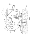
- Fig. 1 shows a bottom ventilation device that can be pulled by means of a tractor.
- the floor ventilation device has a machine frame 2, in which a plurality of upwardly and downwardly movable lancing tools 4 are pivotally mounted.
- the lancing tools 4 are alternately pressed into the bottom 44 and can in the bottom 44 due to the forward movement of the ground ventilation device 1 perform a pivotal movement, in which the bottom 44 is broken below the insertion slot-shaped parallel to the direction of travel, whereby, for example, the ventilation and drainage of the soil 44 is improved.
- the lancing tools 4 are attached individually or as a group to a respective tool holder 6.
- the tool holders 6 are each mounted pivotably on a support arm 5 as a guide element about a pivot axis 7.
- the support arms 5 are moved by means of a drive, preferably a crank mechanism 15, up and down.
- a drive preferably a crank mechanism
- the support arms 5 and the tool holder 6 with the piercing tools 4 are moved up and down, the piercing tools 4 in the bottom 44 are pierced and pulled out again.
- the return arm 58 exerts a restoring force on the tool holder 6, for example by means of a return spring disposed in the return arm 58, so that this and thus also Swing the piercing tools 4 back out of the ground into the starting position.
- a return spring disposed in the return arm 58
- the drive preferably consists of a crank mechanism 15.
- the drive has an output shaft 14.
- the output shaft 14 is a crankshaft.
- the output shaft 14 is arranged transversely to the direction of travel and parallel to the floor 44 and mounted in the machine frame 2 at least on both sides of the floor ventilation device, preferably at several points.
- the output shaft 14 is coupled via a reduction gear 3 with a substantially parallel to the direction of travel main drive shaft 12.
- the main drive shaft 12 is driven by the drive of the tractor.
- the main drive shaft 12 can also be driven by its own engine of the ground ventilation device 1.
- the reduction gear 3 further comprises a drive shaft 16.
- the drive shaft 16 is parallel to the output shaft 14.
- the drive shaft 16 is also mounted on both sides of the ground ventilation device in the machine frame 2.
- the ends of the output and the drive shaft 14,16 stand on at least one side opposite the side walls 10 of the machine frame 2 laterally outward.
- a gear 36 is mounted and rotatably connected thereto.
- the drive shaft 16 drives via the gear 36 and two further gears 34,32 a gear 30 which is rotatably connected to the output shaft 14.
- the gear 30 of the output shaft 14 is disposed on the opposite to the machine frame 2 to the outside projecting free end of the output shaft 14.
- the two gears 32,34 are rotatably connected to a respective axle journal 38,40 which is mounted in each case in the side wall of the machine frame 2.
- the two gears 32,34 are also arranged on the outside of the side wall 10 of the machine frame 2.
- the reduction gear 3 with the gears 30,32,34,36 is of a removable housing or cover enclosed in order to avoid an accident risk during operation and to avoid contamination of the reduction gear.
- This embodiment has the advantage that the gears 30,32,34,36 can be easily removed, since the gears 30,32,34,36 are arranged on the outside of the machine frame 2.
- the gears 30,32,34,36 can be replaced by other gears, each having a different number of teeth and thus other diameters. In this way, the ratio of the reduction gear and thus the hole spacing generated in the direction of travel can be changed in the ground. Thereby, the angular velocity of the crankshaft, which causes the piercing tools 4 are pierced into the ground and pulled out again, can be changed.
- the respective interchangeable gear pairings preferably have the same center distance to each other as the gears 30,32 and 34,36. In this way, no additional stub axle must be stored in the machine frame 2, when the gears 30,32,34,36 to be replaced. It is also possible to change the gear ratio by using the same gear pair and merely changing the position of the smaller or larger gears so that the larger gears take up the position of the smaller gears and vice versa.
- Fig. 2 shows a bottom ventilation device, as in Fig. 1 , with the difference that as a reduction gear 3, a CVT transmission is used.
- a CVT transmission is characterized in that the ratio between the input and output shafts 16,14 can be adjusted continuously. This happens in the embodiment Fig. 2 in that on the opposite to the machine frame 2 to the outside projecting end of the drive shaft 16, a cone pulley pair 46,47 is mounted.
- the cone pulley pair 46,47 is rotatably connected to the drive shaft 16.
- Between the respective conical disks 46,47 runs a belt 43.
- the belt 43 drives a second conical disk pair 45,49, which is rotatably connected to the output shaft 14.
- the two conical disks 46, 47 can be pulled apart in the direction of the drive shaft 16 such that the effective diameter of the conical disks 46, 47 for the belt 43 is reduced, for example, from B to B '.
- the two conical disks will be 45.49 compressed at the same time, so that the effective diameter of the conical disks 45,49 increases.
- the rotational speed of the belt 43 is also changed. In this way, the ratio of the reduction gear 3 is changed.
- Fig. 3 shows a Bodenbelbyungsvorraum, which the embodiments of the FIGS. 1 and 2 is similar.
- the floor ventilation device in Fig. 3 differs in that the reduction gear 3 is a combination of a belt drive and a spur gear.
- a pulley 17 is rotatably attached at the opposite the machine frame 2 to the outside projecting end of the drive shaft 16.
- the pulley 17 drives the gear 28 via a belt 24.
- the gear 28 in turn drives the gear 26 at.
- the two gears 26,28 are each rotatably mounted on a journal 18,20 which is mounted in the machine frame.
- the gear 26 drives the output shaft 14 via a belt 22.
- An advantage of this embodiment is that the belts can slip under overload.
- a chain drive with sprockets could be used. In this embodiment, however, you need as overload protection in addition a slip clutch.
- the two gears 26,28 can be replaced by other gears having a different number of teeth and thus a different diameter.
- the other gears should have the same center distance to each other as the two gears 26,28 so that when replacing the gears not the belt 22,24 must be replaced and additional journals must be provided. The lengths of the belts 22,24 can thus remain constant.
- the ratio of the reduction gear 3 can be changed.
- the gear pairs have, if the interchangeable gear pairs have the same modulus m, the same center distance to each other when the gear pairs each have the same total number of teeth, so that the same mounted in the side wall 10 journals can be used. When replacing the positions only one pair of gears is required if the two gears forming the gear pair do not have the same number of teeth and thus not the same distance to each other.
- Fig. 4 shows an embodiment of the Fig. 3 is very similar. It differs in that instead of the gears 26,28 several gear pairs 26,28 are arranged. These gear pairings each have the same center distance to each other.
- the gears 28 are all non-rotatably connected to the journal 20 and are driven by the drive shaft 16 via the belt 24.
- the gears 26 are all rotatably connected to the journal 18 and drive via the belt 22 to the output shaft 14 at.
- the stub axles 18, 20 are mounted in the machine frame 2.
- the gears 26 are arranged on the journal 18 in other mutual distances from each other as the gears 28 on the journal 20. This allows different gear pairs can be engaged.
- the output shaft 14 can protrude on both sides of the floor ventilation device 1 relative to the machine frame 2 to the outside.
- a reduction gear 3 may be arranged on the two opposite the machine frame 2 protruding ends of the output shaft 14.
- the output shaft 14, which is preferably a crankshaft, may also be divided into two in the longitudinal direction, preferably in the middle.
- Fig. 5 shows a sectional side view of one of the embodiments of the FIGS. 1-4 ,
- the drive shaft 16 is located in the direction of travel A seen behind the output shaft 14, which is a crankshaft in this case.
- a transfer case 9 is arranged between the main drive shaft 12 and the drive shaft 16.
- the main drive shaft 12 is coupled via a universal joint 54 and an intermediate shaft 56 to the transfer case 9.
- the transfer case 9 is preferably arranged centrally within the width of the floor ventilation machine 1.
- the transfer case 9 is also located in the direction of travel A behind the output shaft 14. This has the advantage that the transfer case 9 is not disposed between two crankshaft halves and thereby the push rods 50, as shown Fig. 6 visible, straight.
- Fig. 6 is a rear view of the soil ventilation machine 1 from Fig. 5 shown without rear protective cover. It can be clearly seen that the push rods 50 are rectilinear, whereby the bearing load is symmetrical, since no or only very small lateral forces act on the bearings.
- There is a respective reduction gear 3 is arranged on the outer sides of the two outer walls of the machine frame 2, wherein the reduction gear 3 are enclosed by a respective protective housing 11.
- the reduction gear 3 can from one of the in the FIGS. 1-4 shown reduction gears 3 exist. Alternatively, a manual transmission with the transfer case 9 could be combined.
- Figure 6 has the additional advantage that, characterized in that the transfer case 9 is arranged behind the output shaft 14 seen in the direction of travel, the distance between the pull-bottom ventilation machine 1 and tractor is reduced. This has the advantage that the entire floor ventilation device 1 can be easily lifted by the tractor when it is out of service.
- Fig. 7 shows a Bodenbelbyungsmaschine in which a transfer case 9 is pivotally coupled at the end of the main drive shaft 12.
- the transfer case 9 is preferably arranged centrally within the width of the floor ventilation machine 1.
- the transfer case 9 is seen in the direction of travel in front of the output shaft 14, which is preferably a crankshaft arranged.
- the transfer case 9 is disposed between the main drive shaft 12 and the drive shafts 16.
- the main drive shaft 12 is the input shaft of the transfer case 9.
- the drive shafts 16 extend transversely to the direction A and parallel to the bottom 44.
- each a reduction gear 3 which is adjustable in the gear ratios and couples the drive shafts 16 to the output shaft 14.
- the transfer case 9 can be combined with a manual transmission.
- the manual transmission could for example be a planetary gear or another shiftable gear transmission.
- the combination of transfer case 9 and manual transmission could preferably be coupled on the input side directly with a slip clutch.
- the manual transmission could for example be a planetary gear or another shiftable gear transmission.
- the combination of transfer case 9 and manual transmission could preferably be coupled on the input side directly with a slip clutch.
- the drive shafts 16, the output shaft 14 may be driven, for example via not in the gear ratios adjustable transmission with belts or chains or gears on the sides of the ground ventilation device.
- the embodiment of Figure 7 also has the advantage that the transfer case 9 is not arranged between crankshaft halves. As a result, the push rods 50 are also just executable.
Landscapes
- Life Sciences & Earth Sciences (AREA)
- Engineering & Computer Science (AREA)
- Mechanical Engineering (AREA)
- Soil Sciences (AREA)
- Environmental Sciences (AREA)
- Soil Working Implements (AREA)
- General Details Of Gearings (AREA)
Abstract
Description
Die Erfindung betrifft eine fahrbare Bodenbelüftungsvorrichtung nach dem Oberbegriff des Anspruchs 1.The invention relates to a mobile floor ventilation device according to the preamble of
Derartige Vorrichtungen dienen dazu, mit Hilfe von Stechwerkzeugen Hohlräume in einen Boden einzubringen, wobei in die tieferen Bereiche des Bodens schlitzförmige Hohlräume eingebracht werden und an der Bodenfläche möglichst kleine Löcher auch bei höheren Fahrgeschwindigkeiten verbleiben sollen. Die Hohlräume ermöglichen einen besseren Abfluss von Wasser und Verbessern die Bodenbelüftung und durch die Auflockerung des Bodens wird das Pflanzenwachstum, insbesondere von Gräsern, verbessert.Such devices are used to introduce with the help of piercing tools cavities in a soil, wherein in the deeper areas of the bottom slit-shaped cavities are introduced and the smallest possible holes on the bottom surface should remain even at higher speeds. The cavities allow better drainage of water and improve soil aeration, and soil loosening improves plant growth, especially of grasses.
Aus der Europäischen Offenlegungsschrift
Bei den bisher bekannten Bodenbelüftungsvorrichtung besteht jedoch der Nachteil, dass die Lochabstände der durch die Stechwerkzeuge in den Boden eingebrachten Löcher immer gleich sind. Je nach Untergrund, d.h. je nachdem ob es sich beispielsweise um ein Green bei einem Golfplatz oder ob es sich um einen Fußballplatz handelt, möchte man unterschiedliche Lochabstände haben. Es ist auch bekannt ein Verteilergetriebe zwischen zwei Hälften der Kurbelwelle anzuordnen. Das Verteilergetriebe zwischen den zwei Hälften der Kurbelwelle erfordert viel Platz. Die in den Boden eingebrachten Löcher sollen auch bezogen auf die Breite der Maschine einen gleichen Lochabstand zueinander aufweisen. Um dies zu erreichen sind die Schubstangen, insbesondere die neben dem Verteilergetriebe angeordneten Schubstangen, in Querrichtung gekrümmt, um durch einen axialen Versatz einen gleichmäßigen Abstand der Tragarme für die Einstechwerkzeuge zu ermöglichen. Gekrümmte Schubstangen sind jedoch insbesondere für die Lager nachteilig, da diese Querkräfte aufnehmen müssen.In the case of the previously known floor ventilation device, however, there is the disadvantage that the hole spacings of the holes introduced by the lancing tools into the floor are always the same. Depending on the background, i. Depending on whether it is, for example, a green at a golf course or if it is a football field, you would like to have different hole distances. It is also known to arrange a transfer case between two halves of the crankshaft. The transfer case between the two halves of the crankshaft requires a lot of space. The holes introduced into the ground should also have the same hole spacing from one another with respect to the width of the machine. To achieve this, the push rods, in particular the push rods arranged next to the transfer case, are curved in the transverse direction in order to allow an even spacing of the support arms for the piercing tools by means of an axial offset. However, curved push rods are particularly disadvantageous for the bearings, as they have to absorb shear forces.
Der Erfindung liegt demzufolge die Aufgabe zugrunde, eine Bodenbelüftungsvorrichtung so auszubilden, dass die obengenannten Nachteile vermieden werden und dass die Lochabstände der Löcher, die die Bodenbelüftungsvorrichtung mit Hilfe der Stechwerkzeuge in Fahrtrichtung in den Boden einbringt, auf eine einfache und kostengünstige Weise verändert werden können.The invention is therefore based on the object, a ground ventilation device in such a way that the above-mentioned disadvantages are avoided and that the hole spacing of the holes that brings the ground ventilation device with the help of piercing tools in the direction of travel in the ground, can be changed in a simple and cost-effective manner.
Zur Lösung dieser Aufgabe dienen die Merkmale des Anspruchs 1.To solve this problem serve the features of
Die Erfindung sieht in vorteilhafter Weise vor, dass eine Bodenbelüftungsvorrichtung der einleitend beschriebenen Art, ein Untersetzungsgetriebe aufweist, wobei an dem Untersetzungsgetriebe unterschiedliche Übersetzungsverhältnisse einstellbar sind.The invention advantageously provides that a ground ventilation device of the type described in the introduction has a reduction gear, wherein different gear ratios can be set on the reduction gear.
Dies hat den Vorteil, dass die in Fahrtrichtung verlaufenden Lochabstände der durch die Stechwerkzeuge in den Boden eingebrachten Löcher an unterschiedliche Böden oder Drainage- und Belüftungserfordernisse angepasst werden kann.This has the advantage that running in the direction of travel hole spacings of the introduced through the piercing tools in the ground holes can be adapted to different soils or drainage and ventilation requirements.
Das Untersetzungsgetriebe kann eine parallel zu einer Abtriebswelle verlaufende Antriebswelle aufweisen, die mit der Hauptantriebswelle gekoppelt ist.The reduction gear may include a parallel to an output shaft extending drive shaft, which is coupled to the main drive shaft.
Das Untersetzungsgetriebe kann an einer Außenseite einer das Ende der Kurbelwelle lagernden Wand des Maschinenrahmens angeordnet sein. Dies hat den Vorteil, dass die Teile des Untersetzungsgetriebes leicht zugänglich sind und daher in einfacher Weise ausgetauscht werden können.The reduction gear may be disposed on an outside of a bearing of the end of the crankshaft wall of the machine frame. This has the advantage that the parts of the reduction gear are easily accessible and therefore can be easily replaced.
Das Untersetzungsgetriebe ist vorzugsweise zwischen der Antriebs- und der Abtriebswelle angeordnet.The reduction gear is preferably arranged between the drive and the output shaft.
Das Untersetzungsgetriebe kann ein CVT-Getriebe sein. Dies hat den Vorteil, dass die Übersetzung stufenlos geändert werden kann. Außerdem kann der Riemen bei Überlast durchrutschen, so dass Maschinenteile nicht so schnell beschädigt werden.The reduction gear may be a CVT transmission. This has the advantage that the translation can be changed continuously. In addition, the belt can slip under overload, so that machine parts are not damaged so quickly.
Das Untersetzungsgetriebe kann ein Zahnradgetriebe mit auswechselbaren Zahnradpaarungen sein.The reduction gear may be a gear transmission with interchangeable gear pairs.
Die unterschiedlichen Zahnradpaarungen haben bei benachbarten Zahnrädern vorzugsweise den gleichen Achsabstand. Auf diese Weise können die Zahnradpaarungen in einfacher Weise ausgetauscht werden.The different gear pairings preferably have the same center distance in adjacent gears. In this way, the gear pairs can be easily replaced.
Das Untersetzungsgetriebe kann mindestens zwei auswechselbare Zahnradpaarungen aufweisen, wobei die Zahnräder vorzugsweise in einer Ebene angeordnet sind.The reduction gear may comprise at least two interchangeable gear pairings, wherein the gears are preferably arranged in a plane.
Die Zahnradachsen aller Zahnräder eines Untersetzungsgetriebes können einen gleichen Abstand zueinander aufweisen.The gear axes of all gears of a reduction gear may have an equal distance from each other.
Das Untersetzungsgetriebe kann auch aus einem Schaltgetriebe bestehen. Das kann beispielsweise ein Planetenradgetriebe sein.The reduction gear can also consist of a manual transmission. This can be, for example, a planetary gear.
Die Antriebswelle kann an beiden Außenwänden mit jeweils einem Untersetzungsgetriebe gekoppelt sein und die Untersetzungsgetriebe können eine gemeinsame Abtriebswelle aufweisen.The drive shaft may be coupled to both outer walls with a respective reduction gear and the reduction gear may have a common output shaft.
Das Untersetzungsgetriebe kann eine vorzugsweise integrierte Rutschkupplung aufweisen.The reduction gear can have a preferably integrated slip clutch.
Alternativ könnte anstatt des Untersetzungsgetriebes auch ein Übersetzungsgetriebe oder ein Getriebe mit einem Übersetzungsverhältnis von 1 verwendet werden.Alternatively, instead of the reduction gear, a transmission gear or a transmission with a gear ratio of 1 could be used.
Zwischen Hauptantriebswelle und der mindestens einen Antriebswelle kann ein Verteilergetriebe angeordnet ist. Das Verteilergetriebe kann in Fahrtrichtung gesehen vor der Abtriebswelle angeordnet sein. Alternativ kann das Verteilergetriebe in Fahrtrichtung gesehen hinter der Abtriebswelle angeordnet sein.Between the main drive shaft and the at least one drive shaft, a transfer case is arranged. The transfer case can be arranged in the direction of travel before the output shaft. Alternatively, the transfer case can be seen behind the output shaft seen in the direction of travel.
Das Verteilergetriebe kann mit einem Schaltgetriebe kombinierbar sein.The transfer case can be combined with a manual transmission.
Im folgenden werden unter Bezugnahme auf die Zeichnungen Ausführungsbeispiele der Erfindung näher erläutert.In the following, embodiments of the invention will be explained in more detail with reference to the drawings.
Es zeigen schematisch:
- Fig. 1
- eine Bodenbelüftungsvorrichtung mit einem Stirnradgetriebe am Maschinenrahmen,
- Fig. 2
- eine Bodenbelüftungsvorrichtung mit einem CVT-Getriebe,
- Fig. 3
- eine Bodenbelüftungsvorrichtung mit sowohl einem Stirnradgetriebe als auch einem Riemenantrieb,
- Fig. 3a
- eine Detailansicht des Ausführungsbeispiels aus
Fig.3 , - Fig. 4
- eine Bodenbelüftungsvorrichtung mit einem schaltbaren Stirnradgetriebe,
- Fig. 4a
- eine Detailansicht des Ausführungsbeispiels aus
Fig.4 , - Fig. 5
- eine geschnittene Seitenansicht eines Ausführungsbeispiels mit Verteilergetriebe in Fahrtrichtung gesehen hinter der Abtriebswelle,
- Fig. 6
- eine Rückansicht des Ausführungsbeispiels aus
Fig. 5 , - Fig. 7
- eine geschnittene Seitenansicht eines Ausführungsbeispiels mit Verteilergetriebe in Fahrtrichtung gesehen vor der Abtriebswelle.
- Fig. 1
- a soil ventilation device with a spur gear on the machine frame,
- Fig. 2
- a soil ventilation device with a CVT transmission,
- Fig. 3
- a soil ventilation device with both a spur gear and a belt drive,
- Fig. 3a
- a detailed view of the embodiment
Figure 3 . - Fig. 4
- a ground ventilation device with a switchable spur gear,
- Fig. 4a
- a detailed view of the embodiment
Figure 4 . - Fig. 5
- a sectional side view of an embodiment with transfer case seen in the direction of travel behind the output shaft,
- Fig. 6
- a rear view of the embodiment
Fig. 5 . - Fig. 7
- a sectional side view of an embodiment with transfer case seen in the direction of travel in front of the output shaft.
Die Stechwerkzeuge 4 sind einzeln oder als Gruppe an jeweils einem Werkzeughalter 6 befestigt. Die Werkzeughalter 6 sind jeweils an einem Tragarm 5 als Führungselement um eine Schwenkachse 7 schwenkbar gelagert. Die Tragarme 5 werden mit Hilfe eines Antriebs, vorzugsweise eines Kurbeltriebs 15, auf- und abbewegt. Durch die Auf- und Abbewegung der Tragarme 5 werden auch die Werkzeughalter 6 mit den Stechwerkzeugen 4 auf- und abbewegt, wobei die Stechwerkzeuge 4 in den Boden 44 einstechbar und wieder herausziehbar sind. Parallel zum Tragarm 5 ist ein längenveränderlicher Rückstellarm 58 angeordnet, der einerseits an dem Werkzeughalter 6 und andererseits an dem Maschinenrahmen 2 schwenkbar gelagert ist. Außerhalb des Bodens übt der Rückstellarm 58 beispielsweise durch eine in dem Rückstellarm 58 angeordnete Rückstellfeder eine Rückstellkraft auf den Werkzeughalter 6 aus, so dass dieser und damit auch die Stechwerkzeuge 4 außerhalb des Bodens wieder in die Ausgangslage zurückschwenken. Bezüglich der genauen Ausführung des parallelogrammartig geführten Werkzeughalters sei hier auf die Europäische Offenlegungsschrift
Der Antrieb besteht vorzugsweise aus einem Kurbeltrieb 15. Der Antrieb weist eine Abtriebswelle 14 auf. Im Falle eines Kurbeltriebs 15 ist die Abtriebswelle 14 eine Kurbelwelle. Die Abtriebswelle 14 ist quer zur Fahrtrichtung und parallel zum Boden 44 angeordnet und mindestens an beiden Seiten der Bodenbelüftungsvorrichtung, vorzugsweise an mehreren Stellen, in dem Maschinenrahmen 2 gelagert. Die Abtriebswelle 14 ist über ein Untersetzungsgetriebe 3 mit einer im wesentlichen parallel zur Fahrrichtung verlaufenden Hauptantriebswelle 12 gekoppelt. Die Hauptantriebswelle 12 wird von dem Antrieb der Zugmaschine angetrieben. Alternativ kann bei einer selbstfahrenden Bodenbelüftungsvorrichtung 1 die Hauptantriebswelle 12 auch von einem eigenen Motor der Bodenbelüftungsvorrichtung 1 angetrieben werden.The drive preferably consists of a
Das Untersetzungsgetriebe 3 weist weiter eine Antriebswelle 16 auf. Die Antriebswelle 16 verläuft parallel zu der Abtriebswelle 14. Die Antriebswelle 16 ist ebenfalls auf beiden Seiten der Bodenbelüftungsvorrichtung in dem Maschinenrahmen 2 gelagert. Die Enden der Abtriebs- und die Antriebswelle 14,16 stehen an mindestens einer Seite gegenüber den Seitenwänden 10 des Maschinenrahmens 2 seitlich nach Außen hervor. An dem gegenüber dem Maschinenrahmen 2 nach Außen hervorstehenden freien Ende der Antriebswelle 16 ist ein Zahnrad 36 angebracht und mit dieser drehfest verbunden. Die Antriebswelle 16 treibt über das Zahnrad 36 und über zwei weitere Zahnräder 34,32 ein Zahnrad 30 an, das drehfest mit der Abtriebswelle 14 verbunden ist.The
Das Zahnrad 30 der Abtriebswelle 14 ist an dem gegenüber dem Maschinenrahmen 2 nach Außen hervorstehenden freien Ende der Abtriebswelle 14 angeordnet. Die beiden Zahnräder 32,34 sind drehfest mit jeweils einem Achszapfen 38,40 verbunden, der jeweils in der Seitenwand des Maschinenrahmens 2 gelagert ist. Die beiden Zahnräder 32,34 sind ebenfalls auf der Außenseite der Seitenwand 10 des Maschinenrahmens 2 angeordnet. Das Untersetzungsgetriebe 3 mit den Zahnrädern 30,32,34,36 ist von einem abnehmbaren Gehäuse oder Deckel umschlossen, um eine Unfallgefahr im Betrieb auszuschließen und um eine Verschmutzung des Untersetzungsgetriebes zu vermeiden.The
Diese Ausführungsform hat den Vorteil, dass die Zahnräder 30,32,34,36 leicht abmontiert werden können, da die Zahnräder 30,32,34,36 auf der Außenseite des Maschinenrahmens 2 angeordnet sind. Die Zahnräder 30,32,34,36 können durch andere Zahnräder, die jeweils eine andere Anzahl von Zähnen und somit andere Durchmesser aufweisen, ausgetauscht werden. Auf diese Weise kann die Übersetzung des Untersetzungsgetriebes und damit der in Fahrtrichtung erzeugte Lochabstand im Boden verändert werden. Dadurch kann die Winkelgeschwindigkeit der Kurbelwelle, die bewirkt, dass die Stechwerkzeuge 4 in den Boden eingestochen und wieder herausgezogen werden, verändert werden.This embodiment has the advantage that the
Die jeweiligen austauschbaren Zahnradpaarungen haben vorzugsweise den gleichen Achsabstand zueinander wie die Zahnräder 30,32 und 34,36. Auf diese Weise müssen keine zusätzlichen Achszapfen in dem Maschinenrahmen 2 gelagert sein, wenn die Zahnräder 30,32,34,36 ausgetauscht werden sollen. Es besteht auch die Möglichkeit das Übersetzungsverhältnis dadurch zu ändern, dass die gleiche Zahnradpaarung verwendet wird und lediglich die Position der kleineren bzw. größeren Zahnräder so auszutauschen, dass die größeren Zahnräder die Position der kleineren Zahnräder einnehmen und umgekehrt.The respective interchangeable gear pairings preferably have the same center distance to each other as the
Die beiden Zahnräder 26,28 können durch andere Zahnräder, die eine andere Anzahl von Zähnen und somit einen anderen Durchmesser aufweisen, ausgetauscht werden. Die anderen Zahnräder sollten den gleichen Achsabstand zueinander aufweisen wie die beiden Zahnräder 26,28, damit bei Austausch der Zahnräder nicht auch die Riemen 22,24 ausgetauscht werden müssen und zusätzliche Achszapfen vorgesehen werden müssen. Die Längen der Riemen 22,24 können somit konstant bleiben. Durch einen Austausch der Zahnräder 26,28 durch andere Zahnräder mit einer anderen Anzahl von Zähnen kann die Übersetzung des Untersetzungsgetriebes 3 geändert werden. Die Zahnradpaare weisen, wenn die austauschbaren Zahnradpaare das gleiche Modul m aufweisen, den gleichen Achsabstand zueinander auf, wenn die Zahnradpaare jeweils die gleiche Gesamtanzahl von Zähnen aufweisen, damit die gleichen in der Seitenwand 10 gelagerten Achszapfen verwendet werden können. Bei Austausch der Positionen wird nur ein Zahnradpaar benötigt, wenn die beiden das Zahnradpaar bildenden Zahnräder nicht die gleiche Zähnezahl und somit nicht den gleichen Achsabstand zueinander aufweisen.The two gears 26,28 can be replaced by other gears having a different number of teeth and thus a different diameter. The other gears should have the same center distance to each other as the two
Die Abtriebswelle 14 kann an beiden Seiten der Bodenbelüftungsvorrichtung 1 gegenüber dem Maschinerahmen 2 nach Außen überstehen. Bei den Ausführungsbeispielen aus den
In
Das Ausführungsbeispiel aus
Alternativ kann das Verteilergetriebe 9 mit einem Schaltgetriebe kombinierbar sein. Das Schaltgetriebe könnte beispielsweise ein Planetenradgetriebe oder ein anderes schaltbares Zahnradgetriebe sein. Die Kombination aus Verteilergetriebe 9 und Schaltgetriebe könnte vorzugsweise eingangsseitig direkt mit einer Rutschkupplung gekoppelt sein. Die Kombination aus Verteilergetriebe 9 und Schaltgetriebe ist, genauso wie das Verteilergetriebe 9 alleine, innerhalb der Breite der Bodenbelüftungsmaschine 1 vorzugsweise mittig angeordnet. Das Schaltgetriebe könnte beispielsweise ein Planetenradgetriebe oder ein anderes schaltbares Zahnradgetriebe sein. Die Kombination aus Verteilergetriebe 9 und Schaltgetriebe könnte vorzugsweise eingangsseitig direkt mit einer Rutschkupplung gekoppelt sein. Im Falle einer Kombination aus Verteilergetriebe 9 und Schaltgetriebe könnten die Antriebswellen 16 die Abtriebswelle 14 beispielsweise über nicht in den Übersetzungsverhältnissen einstellbare Getriebe mit Riemen oder Ketten oder Zahnrädern an den Seiten der Bodenbelüftungsvorrichtung antreibbar sein.Alternatively, the
Das Ausführungsbeispiel aus
Claims (14)
dass an dem Untersetzungsgetriebe (3) unterschiedliche Übersetzungsverhältnisse einstellbar sind.Mobile floor ventilation device (1), with
that at the reduction gear (3) different transmission ratios are adjustable.
Priority Applications (5)
| Application Number | Priority Date | Filing Date | Title |
|---|---|---|---|
| EP08153920A EP2106680A1 (en) | 2008-04-01 | 2008-04-01 | Soil ventilation device |
| EP09726891A EP2285204A1 (en) | 2008-04-01 | 2009-03-24 | Soil aeration device |
| US12/935,657 US8561713B2 (en) | 2008-04-01 | 2009-03-24 | Soil aeration device |
| PCT/EP2009/053464 WO2009121758A1 (en) | 2008-04-01 | 2009-03-24 | Soil aeration device |
| CA2720446A CA2720446A1 (en) | 2008-04-01 | 2009-03-24 | Soil aeration device |
Applications Claiming Priority (1)
| Application Number | Priority Date | Filing Date | Title |
|---|---|---|---|
| EP08153920A EP2106680A1 (en) | 2008-04-01 | 2008-04-01 | Soil ventilation device |
Publications (1)
| Publication Number | Publication Date |
|---|---|
| EP2106680A1 true EP2106680A1 (en) | 2009-10-07 |
Family
ID=39671945
Family Applications (2)
| Application Number | Title | Priority Date | Filing Date |
|---|---|---|---|
| EP08153920A Withdrawn EP2106680A1 (en) | 2008-04-01 | 2008-04-01 | Soil ventilation device |
| EP09726891A Withdrawn EP2285204A1 (en) | 2008-04-01 | 2009-03-24 | Soil aeration device |
Family Applications After (1)
| Application Number | Title | Priority Date | Filing Date |
|---|---|---|---|
| EP09726891A Withdrawn EP2285204A1 (en) | 2008-04-01 | 2009-03-24 | Soil aeration device |
Country Status (4)
| Country | Link |
|---|---|
| US (1) | US8561713B2 (en) |
| EP (2) | EP2106680A1 (en) |
| CA (1) | CA2720446A1 (en) |
| WO (1) | WO2009121758A1 (en) |
Cited By (1)
| Publication number | Priority date | Publication date | Assignee | Title |
|---|---|---|---|---|
| CN106068899A (en) * | 2016-06-13 | 2016-11-09 | 江苏大学 | A kind of have rotate forward conveying reversion move back grass function united reaper delivery chute |
Families Citing this family (7)
| Publication number | Priority date | Publication date | Assignee | Title |
|---|---|---|---|---|
| US8297171B2 (en) * | 2010-08-09 | 2012-10-30 | Ben Gagnon | Torque limiter for a gun turret |
| US8925643B2 (en) * | 2012-03-30 | 2015-01-06 | Deere & Company | Aerator with coring depth adjustment |
| HUE050020T2 (en) * | 2012-12-21 | 2020-11-30 | Redexim Handel En Exploitatie Mij B V | Soil working device for working soil and a method for working soil |
| HUE035383T2 (en) * | 2013-01-15 | 2018-05-02 | Redexim Handel En Exploitatie Mij B V | Mobile soil cultivation device with protective device |
| US9915639B2 (en) * | 2014-03-11 | 2018-03-13 | Heriberto Bouza Gonzalez | Agricultural device for restoring soil fertility |
| US10180179B2 (en) | 2017-01-23 | 2019-01-15 | Schiller Grounds Care, Inc. | Chain tension control mechanism |
| US10130024B2 (en) * | 2017-01-23 | 2018-11-20 | Schiller Grounds Care, Inc. | Tine depth stop mechanism for self-propelled, stand-on aerator |
Citations (4)
| Publication number | Priority date | Publication date | Assignee | Title |
|---|---|---|---|---|
| US4753298A (en) * | 1985-01-16 | 1988-06-28 | Outboard Marine Corporation | Turf aerating apparatus |
| US5469922A (en) * | 1993-08-23 | 1995-11-28 | Bjorge; Scott W. | Soil aerator |
| US20020189825A1 (en) * | 1999-12-23 | 2002-12-19 | Livingstone David John | Reciprocating drive mechanism for a turf aerator |
| US20030230417A1 (en) * | 2002-03-12 | 2003-12-18 | Maas David R. | Aeration device |
Family Cites Families (11)
| Publication number | Priority date | Publication date | Assignee | Title |
|---|---|---|---|---|
| US2229497A (en) * | 1939-06-05 | 1941-01-21 | Dontje Emanuel Charles | Spiking apparatus |
| US4153115A (en) * | 1975-06-26 | 1979-05-08 | Lely Cornelis V D | Rotary harrows |
| NL8001412A (en) | 1980-03-10 | 1980-12-31 | J De Ridder Fa | DEVICE FOR APPLYING VERTICAL DRAINING CHANNELS IN GRASS FIELDS, PASTURES, ETC. |
| US4926947A (en) * | 1987-11-16 | 1990-05-22 | Cozine Mark L | Turf aerating apparatus with resilient handle mount |
| US5398767A (en) * | 1988-06-22 | 1995-03-21 | Warke; William L. | Ground treatment apparatus |
| US7055617B2 (en) * | 2003-08-11 | 2006-06-06 | Planetair Turf Products, Llc | Soil aerator |
| US6708773B1 (en) * | 2002-11-12 | 2004-03-23 | Turfco Manufacturing, Inc. | Method and apparatus for an aerator with differential, steering assist and power lifting |
| US7163067B2 (en) * | 2004-03-04 | 2007-01-16 | Wayne Sinclair Job | Ground maintenance apparatus |
| US7163068B2 (en) * | 2004-03-04 | 2007-01-16 | Wayne Job | Hitch assembly |
| AU2008217571B2 (en) * | 2007-02-22 | 2013-07-18 | Greencare Industries Pty Ltd | 'Aerator mechanism with vertically reciprocating tine' |
| US8162071B2 (en) * | 2009-09-14 | 2012-04-24 | Barger K Kent | Soil aerator |
-
2008
- 2008-04-01 EP EP08153920A patent/EP2106680A1/en not_active Withdrawn
-
2009
- 2009-03-24 EP EP09726891A patent/EP2285204A1/en not_active Withdrawn
- 2009-03-24 WO PCT/EP2009/053464 patent/WO2009121758A1/en active Application Filing
- 2009-03-24 US US12/935,657 patent/US8561713B2/en active Active
- 2009-03-24 CA CA2720446A patent/CA2720446A1/en not_active Abandoned
Patent Citations (4)
| Publication number | Priority date | Publication date | Assignee | Title |
|---|---|---|---|---|
| US4753298A (en) * | 1985-01-16 | 1988-06-28 | Outboard Marine Corporation | Turf aerating apparatus |
| US5469922A (en) * | 1993-08-23 | 1995-11-28 | Bjorge; Scott W. | Soil aerator |
| US20020189825A1 (en) * | 1999-12-23 | 2002-12-19 | Livingstone David John | Reciprocating drive mechanism for a turf aerator |
| US20030230417A1 (en) * | 2002-03-12 | 2003-12-18 | Maas David R. | Aeration device |
Cited By (2)
| Publication number | Priority date | Publication date | Assignee | Title |
|---|---|---|---|---|
| CN106068899A (en) * | 2016-06-13 | 2016-11-09 | 江苏大学 | A kind of have rotate forward conveying reversion move back grass function united reaper delivery chute |
| CN106068899B (en) * | 2016-06-13 | 2019-04-30 | 江苏大学 | A combine harvester conveying trough with the function of forward rotation conveying and reverse grass retreating |
Also Published As
| Publication number | Publication date |
|---|---|
| US20110024140A1 (en) | 2011-02-03 |
| CA2720446A1 (en) | 2009-10-08 |
| WO2009121758A1 (en) | 2009-10-08 |
| EP2285204A1 (en) | 2011-02-23 |
| US8561713B2 (en) | 2013-10-22 |
Similar Documents
| Publication | Publication Date | Title |
|---|---|---|
| EP2106680A1 (en) | Soil ventilation device | |
| DE3009662A1 (en) | TRACTOR | |
| DE4119387C2 (en) | Drive device for a motor vehicle | |
| DE2745564A1 (en) | DRIVE DEVICE FOR DRIVABLE WORKING UNITS OF A HARVESTING DEVICE | |
| EP1505862B1 (en) | Soil cultivating device | |
| EP0464374B1 (en) | Drive system | |
| DE3043696C2 (en) | Device for punching perforation holes in lawns | |
| EP1295520B1 (en) | Rotary harrow with improved rotor driving | |
| DE68923546T2 (en) | GRASS TREATMENT DEVICE. | |
| EP0025848B1 (en) | Self-propelled machine with working implements, in particular agricultural machine | |
| DE69304558T2 (en) | Haymaking machine with a frame provided with controlled support wheels | |
| DE2612056A1 (en) | CONTINUOUSLY VARIABLE TRANSMISSION IN PARTICULAR FOR DRIVING POWER CHIPPERS, TRACTORS AND THE LIKE | |
| DE2346116B2 (en) | Gear change gearboxes in group design, especially for agricultural and? or motor vehicles that can be used for construction purposes | |
| DE2515814A1 (en) | TRANSMISSION | |
| DE1534290B2 (en) | TANDEM ROAD ROLLER | |
| AT501304B1 (en) | DEVICE FOR PRODUCING AN ALIGNMENT WITH CHANGING STROKE | |
| DE902097C (en) | Two-axle farm tractor | |
| DE828349C (en) | Additional reduction gear for tractors | |
| AT412522B (en) | PTO-WAVED AGRICULTURAL WORKING DEVICE | |
| EP3932170A1 (en) | Weed separation device | |
| DE102016108032B4 (en) | rotary harrow | |
| DE10103913B4 (en) | Injection unit for a plastic injection molding machine | |
| DE940023C (en) | Gearbox for two-wheel tractors, in particular two-wheel tractor with narrow track width for cultivated tillage machines | |
| DE1159772B (en) | Transmission for tractors, especially agricultural tractors | |
| CH643109A5 (en) | Self-propelled lawnmower |
Legal Events
| Date | Code | Title | Description |
|---|---|---|---|
| PUAI | Public reference made under article 153(3) epc to a published international application that has entered the european phase |
Free format text: ORIGINAL CODE: 0009012 |
|
| AK | Designated contracting states |
Kind code of ref document: A1 Designated state(s): AT BE BG CH CY CZ DE DK EE ES FI FR GB GR HR HU IE IS IT LI LT LU LV MC MT NL NO PL PT RO SE SI SK TR |
|
| AX | Request for extension of the european patent |
Extension state: AL BA MK RS |
|
| 17P | Request for examination filed |
Effective date: 20100326 |
|
| 17Q | First examination report despatched |
Effective date: 20100427 |
|
| AKX | Designation fees paid |
Designated state(s): AT BE BG CH CY CZ DE DK EE ES FI FR GB GR HR HU IE IS IT LI LT LU LV MC MT NL NO PL PT RO SE SI SK TR |
|
| STAA | Information on the status of an ep patent application or granted ep patent |
Free format text: STATUS: THE APPLICATION IS DEEMED TO BE WITHDRAWN |
|
| 18D | Application deemed to be withdrawn |
Effective date: 20141101 |