EP2754091B1 - Messung von bandverschleiss durch randerkennung eines rasterbildes - Google Patents
Messung von bandverschleiss durch randerkennung eines rasterbildes Download PDFInfo
- Publication number
- EP2754091B1 EP2754091B1 EP12830010.0A EP12830010A EP2754091B1 EP 2754091 B1 EP2754091 B1 EP 2754091B1 EP 12830010 A EP12830010 A EP 12830010A EP 2754091 B1 EP2754091 B1 EP 2754091B1
- Authority
- EP
- European Patent Office
- Prior art keywords
- belt
- image
- threshold
- determined
- feature
- Prior art date
- Legal status (The legal status is an assumption and is not a legal conclusion. Google has not performed a legal analysis and makes no representation as to the accuracy of the status listed.)
- Not-in-force
Links
Images


Classifications
-
- G—PHYSICS
- G06—COMPUTING OR CALCULATING; COUNTING
- G06T—IMAGE DATA PROCESSING OR GENERATION, IN GENERAL
- G06T7/00—Image analysis
- G06T7/0002—Inspection of images, e.g. flaw detection
- G06T7/0004—Industrial image inspection
-
- G—PHYSICS
- G06—COMPUTING OR CALCULATING; COUNTING
- G06F—ELECTRIC DIGITAL DATA PROCESSING
- G06F18/00—Pattern recognition
-
- G—PHYSICS
- G06—COMPUTING OR CALCULATING; COUNTING
- G06T—IMAGE DATA PROCESSING OR GENERATION, IN GENERAL
- G06T7/00—Image analysis
- G06T7/10—Segmentation; Edge detection
- G06T7/12—Edge-based segmentation
-
- G—PHYSICS
- G06—COMPUTING OR CALCULATING; COUNTING
- G06T—IMAGE DATA PROCESSING OR GENERATION, IN GENERAL
- G06T7/00—Image analysis
- G06T7/60—Analysis of geometric attributes
- G06T7/62—Analysis of geometric attributes of area, perimeter, diameter or volume
-
- B—PERFORMING OPERATIONS; TRANSPORTING
- B65—CONVEYING; PACKING; STORING; HANDLING THIN OR FILAMENTARY MATERIAL
- B65G—TRANSPORT OR STORAGE DEVICES, e.g. CONVEYORS FOR LOADING OR TIPPING, SHOP CONVEYOR SYSTEMS OR PNEUMATIC TUBE CONVEYORS
- B65G2207/00—Indexing codes relating to constructional details, configuration and additional features of a handling device, e.g. Conveyors
- B65G2207/48—Wear protection or indication features
-
- B—PERFORMING OPERATIONS; TRANSPORTING
- B65—CONVEYING; PACKING; STORING; HANDLING THIN OR FILAMENTARY MATERIAL
- B65G—TRANSPORT OR STORAGE DEVICES, e.g. CONVEYORS FOR LOADING OR TIPPING, SHOP CONVEYOR SYSTEMS OR PNEUMATIC TUBE CONVEYORS
- B65G43/00—Control devices, e.g. for safety, warning or fault-correcting
- B65G43/02—Control devices, e.g. for safety, warning or fault-correcting detecting dangerous physical condition of load carriers, e.g. for interrupting the drive in the event of overheating
-
- G—PHYSICS
- G06—COMPUTING OR CALCULATING; COUNTING
- G06T—IMAGE DATA PROCESSING OR GENERATION, IN GENERAL
- G06T2207/00—Indexing scheme for image analysis or image enhancement
- G06T2207/30—Subject of image; Context of image processing
- G06T2207/30108—Industrial image inspection
Definitions
- the present disclosure is generally directed toward measuring belt wear, and more specifically using images to identify belt wear characteristics and predict belt life.
- Serpentine drive belts are becoming increasingly durable due to the use of Ethylene Propylene Diene Monomer (EPDM) materials.
- EPDM Ethylene Propylene Diene Monomer
- prefailure wear detection is increasingly difficult to quantify.
- serpentine drive belts made of EPDM materials are commonly only diagnosed as excessively worn after a complete failure of the belt.
- embodiments presented herein provide a belt measurement solution that does not require physical contact between a measurement tool and the belt being measured. More specifically, embodiments of the present disclosure contemplate an image-based measurement solution in which one or more images of a belt can be captured. The captured images of the belt may then be analyzed and compared to a database of belt image data. This analysis and comparison, in some embodiments, results in a wear measurement calculation that can subsequently be used to quantify an amount of wear the belt has experienced. Additionally, belt image data can be used to fine tune and optimized equipment running the belt to improve equipment performance.
- measurement of belt wear is achieved through edge detection of rib width of a raster image.
- the edge detection and/or rib width detection includes a process of capturing one or more images of the belt being measured, performing a Gaussian-blur operation on the one or more images, then performing a greyscale conversion of the one or more images, then performing a binary conversion of the one or more images, and then performing a Canny Edge detection operation of the one or more images.
- automatic threshold settings can be determined for binary conversion that yields one region by sampling at discrete levels of gray threshold or alternatively Red/Green/Blue (RGB) values and median value of all thresholds detecting one edge region.
- RGB Red/Green/Blue
- the numbers of ribs in the image(s) are determined by the median value of the ordered sequence of the mode of the detected edge regions.
- belt width and a pixel-to-physical ration can be determined by multiplying the known rib spacing of a particular belt by the detected rib region count and the outer detected edges of the belt.
- the rib region may comprise a four edge outer envelope of the detected rib area as determined by the Canny edge detection algorithm or other edge detection algorithm.
- a method is provided to identify a belt as overly-worn or failed by determining that (i) the detected number of ribs, (ii) belt width, and/or (iii) pixel/mm or pixel/in ratio in an image are inconsistent with the ideal thresholds of such metrics.
- these metrics for a belt may be processed by a rejection/validation algorithm which comprise these metrics with known or preferred metrics for the same type of belt and if the comparison reveals that the belt being measured is not within a predetermined range of the ideal thresholds, then the belt being measured may be rejected.
- automated refers to any process or operation done without material human input when the process or operation is performed. However, a process or operation can be automatic, even though performance of the process or operation uses material or immaterial human input, if the input is received before performance of the process or operation. Human input is deemed to be material if such input influences how the process or operation will be performed. Human input that consents to the performance of the process or operation is not deemed to be "material”.
- Non-volatile media includes, for example, NVRAM, or magnetic or optical disks.
- Volatile media includes dynamic memory, such as main memory.
- Computer-readable media include, for example, a floppy disk, a flexible disk, hard disk, magnetic tape, or any other magnetic medium, magneto-optical medium, a CD-ROM, any other optical medium, punch cards, paper tape, any other physical medium with patterns of holes, a RAM, a PROM, and EPROM, a FLASH-EPROM, a solid state medium like a memory card, any other memory chip or cartridge, or any other medium from which a computer can read.
- the computer-readable media is configured as a database, it is to be understood that the database may be any type of database, such as relational, hierarchical, object-oriented, and/or the like. Accordingly, the disclosure is considered to include a tangible storage medium and prior art-recognized equivalents and successor media, in which the software implementations of the present disclosure are stored.
- module refers to any known or later developed hardware, software, firmware, artificial intelligence, fuzzy logic, or combination of hardware and software that is capable of performing the functionality associated with that element. Also, while the disclosure is described in terms of exemplary embodiments, it should be appreciated that individual aspects of the disclosure can be separately claimed.
- embodiments of the present disclosure may be utilized to capture one or more images of an object that undergoes expansion and/or contraction due to thermal fluctuations. These expansions and/or contractions may result in the object becoming fatigued and, eventually, failing.
- the image-based measurement processes disclosed herein may be used to analyze objects undergoing such thermal expansion and/or contraction and, if necessary, identify the objects as being good (e.g., not requiring a replacement) or bad (e.g., requiring a replacement).
- the embodiments described herein can be used to determined frictional-induced wear conditions for any type of belt.
- the belt that is analyzed may be constructed of any material or combination of materials including, without limitation, rubber, polymer, polyethylene, carbon fiber, Kevlar, metal, polyvinyl chloride, and/or foam.
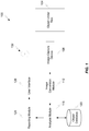
- the measurement system 100 may comprise one or more components for analyzing an object under test 104 and classifying the object under test 104 as either good (e.g., not requiring a replacement) or bad (e.g., requiring a replacement). Other determinations may be made for the object under test 104 without departing from the scope of the present disclosure; for instance, the object under test 104 may be identified as failing (e.g., soon requiring a replacement) or abnormal (e.g., not following an expected wear pattern and, therefore, requiring further investigation and/or replacement).
- the measurement system 100 comprises an image-capture device 108, an image conversion module 112, an analysis module 116, an object database 120, a reporting module 124, and a user interface 128.
- each component of the system 100 may be included in a single computing device that is owned and operated by a user 132.
- every component of the measurement system 100 may be included in a user device such as a cellular phone, smart phone, Personal Computer (PC), laptop, netbook, tablet, or the like.
- the components of the measurement system 100 may be distributed among two or more different computing devices.
- the image-capture device 108 is configured to capture one or more images of the object under test 104.
- the object under test 104 may comprise a belt, specifically a serpentine belt made of EPDM materials.
- the belt may either be located in an operational position (e.g., mounted on a vehicle or other device which employs the belt) or it may be in a non-operational position (e.g., removed from a vehicle or other device which employs the belt).
- the image-capture device 108 may be capable of capturing one or more still images.
- the image-capture device 108 may be capable of capturing video images (e.g., a sequenced number of image frames which may or may not be synchronized with an audio input).
- the image(s) captured by the image-capture device 108 may comprise color (e.g., a pixel image where each pixel comprises a Red, Green, and Blue (RGB) pixel value), greyscale (e.g., a pixel image where each pixel comprises a greyscale pixel value between 0 and a predetermined number such as 255), black-and-white (e.g., a pixel image where each pixel comprises a binary value corresponding to either a black or white), infrared (e.g., a pixel image where each pixel comprises an infrared pixel value), ultraviolet (e.g., a pixel image where each pixel comprises an ultraviolet value), or any other known type of image.
- a non-limiting example of the image-capture device 108 is a camera (still or video
- the image conversion module 112 is provided to perform image conversions of the image(s) captured by the image-capture device 108 before the image(s) are analyzed by the analysis module 116.
- the image conversion module 112 may comprise one or more image filters and/or processing algorithms for detecting contour edges of the object under test 104 in the image(s).
- the image conversion module 112 is configured to convert greyscale and/or RGB images into black-and-white images by performing one or more edge-detection processes.
- the analysis module 116 is configured to analyze the image(s) of the object under test 104 to determine one or more physical characteristics of the object under test 104.
- the analysis module 116 may reference an object database 120 to determine the physical characteristics of the object under test 104.
- the object database 120 may comprise data for a number of different types of objects (e.g., serpentine belts), and each of the different types of objects may have example images for a good object of that type and a bad object of that type.
- the analysis module 116 may compare the image(s) captured by the image-capture device 108 with the images in the object database 120 to determine whether the object under test 104 is more similar to a good object or a bad object.
- the object database 120 may comprise one or more metrics and thresholds that define acceptable (or unacceptable) measurements for each of the different types of objects.
- the analysis module 116 may extract physical dimension data and other physical metrics from the image(s) and compare the physical dimension data of the object under test 104 with the metrics and thresholds in the object database 120. This comparison can be used to determine whether the object under test 104 is a good object or a bad object.
- Results obtained by the analysis module 116 may be provided to a reporting module 124, which is configured to prepare a report of the analysis results to the user 132.
- the reporting module 124 may comprise functionality to format a report that identifies whether the object under test 104 has been identified as good or bad and whether any further steps should be taken in connection with such a determination.
- the reporting module 124 may also comprise functionality to transmit the report to the user interface 128.
- the reporting module 124 may comprise functionality to prepare a report (or reporting statistics) and transmit the report to the user interface 128 via any type of communication protocol.
- the user interface 128 may comprise a user input and/or user output device.
- the user interface 128 comprises a user output that enables the user 132 to see the results of the report generated by the reporting module 124.
- the communication system 200 may comprise one or more devices that incorporate the components of the measurement system 100. Although certain components of the measurement system 100 are depicted as being included in certain components of the communication system 200, those skilled in the communication arts will appreciate that the various components of the measurement system 100 may be distributed among one or more devices of the communication system 200 in any number of ways. For instance, all of the components of the measurement system 100 may be included in a single user device 208. Alternatively, one or more components of the measurement system 100 may be provided on one or more other user devices, on one or more servers 240, a collection of servers, or any other similar device.
- the communication system 200 comprises a user device 208 in communication with one or more servers 240 via a communication network 204.
- the user device 208 comprises any type of known communication device or collection of communication devices. Examples of a suitable user device 208 include, but are not limited to, a personal computer (PC), laptop, netbook, Personal Digital Assistant (PDA), cellular phone, smart phone, telephone, or combinations thereof.
- the user device 208 may be adapted to support video, image, audio, text, and/or data communications with other user devices as well as the server 240.
- the type of medium used by the user device 208 to communicate with other user devices or server 240 may depend upon the nature of the communication module 228 available on the user device 208.
- the server 240 may comprise any type of processing resources dedicated to performing certain functions discussed herein.
- the server 240 may comprise a web server having hardware and software that helps to deliver content that can be accessed through the communication network 204.
- One function of a web server is to deliver web pages on the request to clients (e.g., the user device 208). This means delivery of one or more documents to the user device 208 via any type of markup language (e.g., HyperText Markup Language (HTML), extensible Markup Language (XML), and the like) and any additional content that may be included by a document, such as images, style sheets and scripts.
- markup language e.g., HyperText Markup Language (HTML), extensible Markup Language (XML), and the like
- HTML HyperText Markup Language
- XML extensible Markup Language
- the server 240 may comprise the ability to receive requests or other data from the user device 208, where the requests are formatted according to a mutually-agreed upon protocol (e.g., HyperText Transport Protocol (HTTP), Realtime Transport Protocol (RTP), secure variants thereof, or the like).
- HTTP HyperText Transport Protocol
- RTP Realtime Transport Protocol
- the request may comprise a request for a specific resource using HTTP and it may further comprise a request to perform one or more operations prior to providing a response thereto.
- the server 240 may locate the requested resource and/or perform one or more operations prior to returning a response to the requesting user device 208 by using the same or a different type of protocol.
- the communications between the server 240 and user device 208 may be facilitated by the communication modules 228, 244.
- the communication module 228 of the user device 208 may comprise a web browsing application (e.g., Internet Explorer®, Mozilla Firefox, Safari®, Google Chrome®, or the like) that enables the user device 208 to format one or more requests and send the requests to the server 240.
- the communication module 244 of the server 240 may comprise the functionality required to execute one or more scripts and respond to requests from the user device 208.
- the communication module 244 may be provided on a dedicated web server while the other components of server 240 (e.g., analysis module 116 and reporting module 124) are provided on a different server that is connected to the web server. In either configuration, the analysis module 116 and reporting module 124 may be made available to the user device 208 via the communication module 244 and the reporting module 124 may be configured to send reports or report results back to the user device 208 via the communication module 244.
- the communication network 204 may include wired and/or wireless communication technologies.
- the Internet is an example of the communication network 204 that constitutes and Internet Protocol (IP) network consisting of many computers, computing networks, and other communication devices located all over the world, which are connected through many telephone systems and other means.
- IP Internet Protocol
- Other examples of the communication network 204 include, without limitation, a standard Plain Old Telephone System (POTS), an Integrated Services Digital Network (ISDN), the Public Switched Telephone Network (PSTN), a Local Area Network (LAN), a Wide Area Network (WAN), a Session Initiation Protocol (SIP) network, a cellular network, and any other type of packet-switched or circuit-switched network known in the art.
- POTS Plain Old Telephone System
- ISDN Integrated Services Digital Network
- PSTN Public Switched Telephone Network
- LAN Local Area Network
- WAN Wide Area Network
- SIP Session Initiation Protocol
- cellular network any other type of packet-switched or circuit-switched
- the communication module 228 of the user device 208 may be stored in memory 216 along with other instructions, scripts, etc., which may be referred to generally as applications.
- an Operating System (O/S) 220 and testing application 224 may be provided as instructions in memory 216 and these instructions may be executed by the processor 212 of the user device 208.
- the processor 212 may comprise one or more Integrated Circuits (ICs), a Digital Signal Processor (DSP), an Application Specific IC (ASIC), a controller, a Programmable Logic Device (PLD), a logic circuit, or the like.
- the processor 212 may comprise a general-purpose programmable processor controller for executing application programming or instructions stored in memory 216.
- the processor 212 may comprise multiple processor cores and/or implement multiple virtual processors.
- the processor 212 may comprise a plurality of physically different processors.
- the memory 216 may comprise any device or collection of devices configured for the short-term or long-term storage of information (e.g., instructions, data, etc.).
- the memory 216 may comprise Random Access Memory (RAM), any known variant of RAM, solid-state memory, any known variant of solid-state memory, Read Only Memory (ROM), any known variant of ROM, or combinations thereof.
- RAM Random Access Memory
- ROM Read Only Memory
- the memory 216 may not only be used to store the applications for execution by the processor 212, but it may also be used as processing memory (e.g., cache, RAM, etc.) by the processor 212.
- the memory 216 may comprise a hard-disk drive or the like.
- the O/S 220 may correspond to any type of known operating system or system platform. In some embodiments, the type of O/S 220 used may depend upon the nature of the user device 208.
- the O/S 220 represents a high-level application that allows a user to navigate and access the various other applications stored in memory 216.
- the O/S 220 may also comprise one or more Application Programming Interfaces (APIs) or API-like rules that allow the applications to access and/or control the various other software and/or hardware components of the user device 208.
- APIs Application Programming Interfaces
- the testing application 224 may enable the user device 208 to perform one or more functions in connection with testing the object under test 104.
- the testing application 224 may comprise functionality similar to the image conversion module 112, analysis module, and/or reporting module 124. More specifically, the testing application 224 may comprise an application on the user device 208 that allows a user 132 to operate the image-capture device 108 and capture one or more images of the object under test 104.
- the testing application 224 may also be configured to format the images captured by the image-capture device 108 for transmission to the server 240 and/or analysis by the analysis module 116. In some embodiments of the analysis module 116 may also be included in the testing application 224.
- the testing application 224 can also be configured to determine physical metrics about the object under test 104 based on the images obtained thereof.
- the user device 208 may further comprise the user interface 128, a power source 232, and a network interface 236.
- the user interface 128 may comprise one or more user inputs (e.g., microphone, camera, buttons, keys, scanners, etc.), one or more user outputs (e.g., speaker, lights, display screens, etc.), and/or one or more combined user input/output devices (e.g., touch-sensitive display screen, illuminated button, etc.).
- the power source 232 may comprise a dedicate power source for the user device 208 such as a battery, one or more capacitors, and the like.
- the power source 232 may additionally, or alternatively, comprise power adaptors for converting A/C power from an external power source into DC power that is useable by the various components of the user device 208.
- the network interface 236 may comprise one or more devices, ports, controllers, drivers, etc. that enable the user device 208 to connect with and communicate via the communication network 204.
- the network interface 236 may comprise components that facilitate wired and/or wireless connections with the communication network 204.
- the network interface 236 may comprise one or more wireless interfaces that facilitate cellular communications with a cellular communication network, an 802.11X compliant interface, an Ethernet port, or the like.
- the communication module 228 of the user device 208 may facilitate other types of communications such as voice, video, text, email, multi-media, etc. with other user devices.
- the communication module 228 may comprise functionality that enables the user device 208 to perform voice calls, video calls, send/receive Short Message Service (SMS) messages, send/receive Multi-Media Service (MMS) messages, and the like.
- SMS Short Message Service
- MMS Multi-Media Service
- a data structure 300 that may be maintained in the object database 120 will be described in accordance with embodiments of the present disclosure. It should be appreciated that the data structure 300 may be maintained completely in the object database 120 and may be retrieved therefrom. In some embodiments, a structured language such as Structured Query Language (SQL) may be followed by the analysis module 116 to perform database lookups and retrieve information from the data structure 300. Alternatively, or in addition, the data structure 300 may be maintained in memory of the server 240 and/or in memory 216 of the user device 208.
- SQL Structured Query Language
- the data structure 300 may comprise a plurality of data fields that can be used by the analysis module 116 to analyze the object under test 104 (or an image thereof) and determine if the object under test 104 is good, bad, or has some other characteristics that may effect its operation.
- the fields that may be included in the data structure 300 may comprise, without limitation, a belt identifier field 304, a rib count field 308, a rib profile field 312, an image overlay data field 316, a thresholds field 320, a wear history field 324, and a replacement history field 328.
- the belt identifier field 304 may be used to store information for identifying any type of object under test 104. If the object under test 104 is a belt, such as a serpentine belt, then the belt identifier field 304 may comprise one or more of a part number, a model number, a Universal Purchase Code (UPC), a part name, a model name, and any other information that can be used to identify the belt. As can be appreciated, if the object under test 104 is not a belt, then any other information specific to that object may be stored in the belt identifier field 304.
- UPC Universal Purchase Code
- the rib count field 308 may be used to store information that identifies the number of ribs on a particular belt type. Alternatively, or in addition, the rib count field 308 can store information that identifies the number of grooves on the belt or any other feature that maintains the belt in a normal operational position.
- the rib profile field 312 may be used to store information that identifies physical characteristics of the rib(s) or spaces between the ribs on the belt. For example, the rib profile field 312 may store information that identifies whether the ribs are v-shaped, square-shaped, rounded, etc. The rib profile field 312 may also store information related to manufactured distances between ribs and the like. Any information that identifies a good (expected) profile or a bad (unexpected) profile for the belt may be maintained in the rib profile field 312.
- the image overlay data field 316 may be used to store any image data that is used for overlay purposes.
- the image overlay data field 316 may comprise a number of images of a belt of a particular type. The images may vary from images of good belts to images of bad belts.
- the image overlay data field 316 may also comprise one or more images of an object under test 104.
- the image overlay data field 316 may also comprise results of an image overlay process after an image of the object under test 104 is compared to one or more stored images of example belts with known physical properties.
- the image overlay data field 316 may be used to store data that identifies the results of an image overlay process (e.g., which among a plurality of stored example images the image of the object under test 104 is most similar to and physical properties of the stored example image that is most similar to the image of the object under test 104).
- the thresholds data field 320 may comprise one or more thresholds for determining whether an object under test 104 is good, bad, or some other state.
- the thresholds field 320 may comprise information about one or more belt physical properties that if met, exceeded, etc. by the object under test 104, result in a determination that the object under test 104 is bad, good, etc.
- the wear history data field 324 may be used to store information related to historical wear observations for the specific object under test 104 or other objects of similar types. For example, if a belt of a particular type is observed to have an excessive amount of wear on one or more specific ribs (e.g., internal ribs, external ribs, one rib in particular, outer edges, etc.), then such information can be maintained in the wear history filed 324.
- the wear history field 324 is useful to manufacturers of objects similar to the object under test 104 so that field wear history can be maintained, analyzed, and hopefully used to produce better objects in the future.
- data in the wear history field can be used to fine tune equipment that is using the belt in operation, thereby allowing the equipment (e.g., vehicle, motor, machine, etc.) to continue running optimally as the belt wears.
- the replacement history field 328 can be used to store information about the replacement history of a particular object under test 104 or similar types of objects to the object under test.
- the replacement history field 328 can identify the amount of use a particular object under test 104 has experienced before it received a grade of bad and had to be replaced. This information can be shared between the manufacturer of the object under test 104 and the consumer of the object under test 104. Additionally, this information can be used to inform maintenance personnel that if an object of a particular type has experienced a certain amount of use, then it may at least be time to subject that object to one or more of the testing procedures described herein.
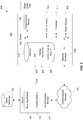
- Fig. 4 details of a testing procedure will be described in accordance with embodiments of the present disclosure.
- the method described herein will be directed toward the particular situation where a belt is the object under test 104; however, those of ordinary skill in the art will appreciate that one or more of the steps described herein may be used for testing objects of other types for any type of wear.
- the first step may be to mark the belt with one or more indicators that create a visible contrast on one or more features of the belt (step 404).
- the belt may be marked during its manufacture at one or more predetermined locations and this may be all that is required during the belt-marking step.
- the belt may not be manufactured with any particular mark that will be used for testing of the belt. Rather, the belt may be marked just prior to taking one or more images of the belt.
- the belt may be marked with a highlighter, pen, marker, or the like to create one or more contrasting objects on the belt. The types of features of the belt that are marked may depend upon the type of wear that is being tested on the belt.
- the belt may be designed to wear at its ribs, then one, two, three, four, or all of the ribs of the belt may be marked at a common point on the belt with a marker or the like. Alternatively, the belt may be marked in its valleys or at other predetermined locations on the belt. In other embodiments, the belt may have a premanufactured feature that only becomes visible as the belt wears. Specifically, the belt may comprise a number of layers of EPDM materials, and one of those layers may comprise a different coloring than the other layers in the belt. Accordingly, as the belt wears, the layer of the other color may become exposed and this may be sufficient to mark the belt in accordance with embodiments of the present disclosure.
- the method proceeds with the image-capture device 108 obtaining one or more images of the belt at the location(s) in which it has been marked (step 408).
- the image(s) can be obtained using still-image cameras, video cameras, etc.
- the image data may comprise any type of known image file formats that is a standardized mechanisms of organizing and storing digital images.
- the image file(s) may be composed of either pixels, vector (geometric) data, or a combination of the two. Whatever the format, the files are rasterized to pixels when displayed on most graphic displays.
- the pixels that constitute an image are ordered as a grid (columns and rows); each pixel consists of numbers representing magnitudes of brightness and color for a specific location within the image. It should be appreciated that any type of image file may be used to transport the image data to the analysis module.
- Non-limiting examples of such image files include JPEG, Exif, TIFF, RAW, PNG, GIF, BMP, PPM, PGM, PBM, PNM, WEBP, CGM, Gerber Format (RS-274X), SVG, PNS, JPS, or any other type of known or yet-to-be-developed image format.
- the transmission step may also comprise formatting the image file(s) such that the image data can be communicated to the analysis module 116 via the communication network 204. Accordingly, the image file(s) may be packetized and formatted for transmission across the communication network 204 (e.g., within one or more communication packets transmitted via the Internet).
- the image(s) may be formatted for edge detection by the image conversion module 112 (step 416). Depending upon the location of the image conversion module 112, this step may be performed before or after transmission of the image data. For instance, if the image conversion module 112 and analysis module 116 reside on the same device, then the transmission may occur before the formatting. However, if the image conversion module 112 and analysis module 116 reside on different devices, then the transmission may occur after the formatting.
- the image data may be converted to greyscale (if the images were originally obtained as color images), one or more filters may be applied to the image data (e.g., application of Gaussian Blur to smooth out any image noise and filter out other unwanted image data), the image data may be converted to binary data such as a black-and-white image (e.g., by applying a binary threshold algorithm to the greyscale image to convert any pixel above the threshold to one color (e.g., black) and convert any pixel equal to or below the threshold to the other color (e.g., white)).
- a binary threshold algorithm e.g., by applying a binary threshold algorithm to the greyscale image to convert any pixel above the threshold to one color (e.g., black) and convert any pixel equal to or below the threshold to the other color (e.g., white)
- the method continues with the analysis module 116 locating one or more contours (e.g., identifying objects) within the image data (step 420).
- the analysis module 116 may be configured to perform a Canny Edge Detection process. Other types of edge or blob-detection techniques may be employed without departing from the scope of the present disclosure.
- Examples of such techniques include, without limitation, Canny-Deriche, Differential, Sobel, Prewitt, Roberts Cross, Interest point detection, Corner detection, Harris operator, Shi and Tomasi, Level curve curvature, SUSAN, FAST, Laplacian of Gaussian (LoG), Difference of Gaussians (DoG), Determinant of Hessian (DoH), Maximally stable external regions, PCBR, Hough transform, Structure tensor, Affine invariant feature detection, Affine shape adaptation, Harris affine, Hessian affine, and so on.
- step 424 it may be determined if any threshold adjustments are necessary. Specifically, based on the results of the contour detection of step 420, all of the contours within the image data may be located. If a number of features (e.g., ribs) are detected and that number of detected features does not equal the expected number of features, then it may be necessary to adjust one or more thresholds that were used during the image formatting (step 428). As an example, the threshold(s) used to convert an image to a black-and-white image may be adjusted by using a bi-directional solver for thresholds that yields the expected number of features (e.g., ribs).
- a number of features e.g., ribs
- the method may be allowed to proceed out of the threshold-adjustment loop to a step where the image data is scaled and checked for errors (step 432).
- this step may be where the analysis module 116 converts the pixel data of the image to physical dimension information (e.g., the actual size of the belt is determined based on the size of the belt in the image, the actual size of the features (e.g., ribs) are determined based on the size of the features in the image, etc.).
- the size of the marked areas on the belt may be determined in physical units (e.g., area, linear dimensions, etc.) (step 436).
- the topmost and bottommost edges detected on the belt may be used to determine the scaling ratio.
- This scaling ratio can be determined in many situations because the type of belt being tested would be known and communicated to the analysis module 116, the width of that type of belt may be known to the analysis module 116 via the object database 120.
- the known length of the belt from the object database 120 may be equated to the detected width of the belt in the image (which is in pixels) and this ratio of physical units to pixel units may be used as a pixel-to-physical unit conversion ratio for the other objects in the image.
- the user 132 that obtains the image of the belt may also obtain a width measurement of the belt being tested and may provide that data to the analysis module 116 for purposes of converting pixel values to physical values.
- an image may be captured of an object of a known or standard size (e.g., ruler, penny, quarter, dollar bill, etc.) and the image of the object of a known or standard size may be used to convert pixel units to physical units.
- the object of a known or standard size may be included in the image of the belt or it may be obtained in an image separate from the image of the belt.
- Another analysis step that may be performed by the analysis module 116 is an image overlay step where the image of the belt being tested is overlaid against one or more images of belts having known physical dimensions (step 440).
- An alternative image overlay step may involve the analysis module 116 overlaying the calculated dimensions of the marked features (e.g., rib width dimensions) against the original image such that the user 132 can check to ensure that the analysis module 116 has accurately identified the features of the belt from the image.
- the features analyzed by the analysis module 116 may include the size, shape, and/or distance between marked portions of the belt and/or size, shape, and/or distance between unmarked portions of the belt.
- Fig. 6 an overlaid image which may be used in accordance with embodiments of the present disclosure is depicted in Fig. 6 where the calculated areas of certain features are overlaid against the actual image.
- the analysis module 116 may determine that the object (e.g., belt) is either good, bad, etc. and based on this determination, the analysis module 116 may generate one or more warning conditions regarding the condition of the object (step 444). Alternatively, or in addition, the analysis module 116 may generate other statistics about the belt such as predicted use history based on detected wear, proposed next steps (e.g., re-check the belt in X time, replace the belt and check the new belt in Y time, abnormal wear detected therefore check other components that interface with belt, etc.).
- the warning conditions or other results of the analysis may then be reported back to the user 132 (step 448).
- the reports of the analysis may be transmitted in one or more communication packets over the communication network 204, unless the analysis module 116 resides on the user device 208 or some other device that is co-located with the user interface 128.
- optimum threshold value a greyscale value somewhere between 0 and 255
- the values of Tmin and Tmax may be solved using a binary method. Once solved, the values of Tmin and Tmax may be used to determine an optimum threshold, which equals the average greyscale value of Tmin and Tmax.
- An alternative, or perhaps complimentary, algorithm for determining the threshold value will be described in further detail with reference to Figs. 9-11 .
- the image of the belt 600 may be converted into a binary image and analyzed by the analysis module 116. Based on this analysis, the detected edges or contours may be overlaid onto the actual image to produce the overlaid image 600.
- the types of features that may be detected by the analysis module 116 include one or more markings 608a-N on the ribs 612a-N of the belt, a first edge 616 (e.g. topmost edge) of the belt, and a second edge 620 (e.g., bottommost edge) of the belt.
- the markings 608a-N may be detected within a zoom window 604 that identifies the region of interest within the image.
- the zoom window may be automatically generated and positioned about the plurality of markings 608a-N.
- a user 132 may interact with the testing application 224 to manually identify the zoom window 604 to help the analysis module 116 focus its analysis on the contours within the zoom window 604.
- part of the testing application's 224 operation may instruct the user 132 to select the area of the zoom window 604 such that the plurality of markings 608a-N are within the zoom window 604 and the first and second edges 616, 620 are also within the zoom window 604.
- This can also help the analysis module 116 to create a more accurate conversion of pixel values to physical values.
- the edges 616, 620 may become relatively easy to distinguish from the markings 608a-N because the edges 616, 620 traverse the entire width of the zoom window 604 whereas the markings 608a-N do not.
- the analysis module 116 may use this fact and a simple rule that states if a contour is detected as traversing the entire width of the zoom window 604, then that contour may be treated as one of the edges 616, 620, whereas if a contour is detected as not traversing the entire width of the zoom window 604, then that contour may be treated as a marking 608.
- the center of each detected rib may then be calculated according to the equation above and the image may be rejected if the difference between the detected rib position and the expected rib position is too great (e.g., exceeds a predetermined threshold).
- Figs. 7A-D depict examples of an image of an object under test 104 during various stages of the image analysis.
- Fig. 7A depicts an original image of a belt, which may have been originally in greyscale or color.
- Fig. 7B depicts a greyscale conversion of the image in Fig. 7A if the image in Fig. 7A was originally in color.
- Fig. 7C depicts the image after a filter (e.g., Gaussian Blur) has been applied to the image of Fig. 7B.
- Fig. 7D depicts the image of Fig. 7C after the image has been converted to a black-and-white image. It is this image which may be analyzed by the analysis module 116 to detect edges in the image (e.g., marked features of the belt).
- a filter e.g., Gaussian Blur
- Fig. 8 depicts one example of a user interface presentation that may be provided to a user 132 after the image has been analyzed by the analysis module 116.
- the presentation may be provided on the user interface 128 of the user device 208 and the presentation may comprise a first presentation area 808 where the original image within a zoom window 604 is depicted, a second presentation area 812 where the analyzed black-and-white image is depicted (or possibly where an overlay image is depicted), a submit button 816, a results display portion 820, an image-capture button 824, an analyze button 828, and a settings button 832.
- the submit button 816 may cause the user device 208 to transmit the image from the first presentation area 808 to the analysis module 116 and the overlay image 600 may be presented in the second presentation area 812.
- the results display portion 820 may be used to display statistical results, recommended remedial actions, historical wear data, and other data obtained from the analysis of the image and/or data obtained from the object database 120.
- the results display portion 820 may also display any assumptions made by the analysis module 116 in analyzing the object under test 104.
- the buttons 824, 828, 832 may be used to cause the testing application 224 to perform one or more actions associated with the button.
- the image-capture button 824 may cause the user device 208 to activate the image-capture device 108 and capture an image of the object under test 104.
- the analyze button 828 may cause the user device 208 to format and send the captured image to the analysis module 116 for testing.
- the settings button 832 may enable a user 132 to configure settings of the testing application 224 and perform other administrative tasks.
- the interface may also comprise an area where a user is allowed to provide feedback information to the analysis module 116 (e.g., other comments related to wear of the object under test 104, comments on the accuracy of the analysis, comments on the accuracy of the assumptions, etc.).
- a dialog box which enables a user 132 to directly access the object database 120.
- Other types of dialog boxes, buttons, etc. may also be made available to a user 132 without departing from the scope of the present disclosure.
- the threshold-selection algorithm begins by sampling an image of a belt (or other type of object) using a grey threshold between two extremes (e.g., 0 to 256 or any other discrete levels between two binary colors). At each sampled threshold, the number of ribs on the belt is detected ( Fig. 9 ). The analysis module 116 may be configured to step though each candidate threshold and determine a number of ribs detected at each candidate threshold until the entire plot of Fig. 9 is created.
- the analysis module 116 may find the mode rib count (e.g., the most-often occurring rib-count value obtained from the test set summarized in Fig. 9 ). The rib-count data may then be incorporated into another data set that correlates a rib count to a number of occurrences for that rib count ( Fig. 10 ).
- mode rib count e.g., the most-often occurring rib-count value obtained from the test set summarized in Fig. 9 .
- the rib-count data may then be incorporated into another data set that correlates a rib count to a number of occurrences for that rib count ( Fig. 10 ).
- the six ribs was determined to have the most occurrences of any other rib count. Accordingly, the data set from Fig. 9 may then be filtered with the most-frequent rib count from Fig. 10 to result in a filtered data set that is depicted in Fig. 11 .
- the threshold values in Fig. 11 represent only the threshold values obtained for the rib count of six (e.g., the most frequently-occurring rib count).
- the analysis module 116 may use the filtered data from Fig. 11 to determine a more accurate threshold value for converting a grayscale image into a black-and-white image. Specifically, the analysis module 116 may determine a median or mean threshold value from the filtered data. By analyzing the filtered data, the analysis module 116 will be configured to ignore certain outliers (e.g., thresholds that result in the detection of 15 ribs) and, therefore, obtain a more useful threshold value.
- certain outliers e.g., thresholds that result in the detection of 15 rib
- the above-described algorithm for determining a threshold value may be used in determining a grayscale threshold value, a color threshold value, or a threshold value for any other type of pixel data.
- the above-described algorithm is not intended to be limited to the conversion of grayscale images to black-and-white images.
- machine-executable instructions may be stored on one or more machine readable mediums, such as CD-ROMs or other type of optical disks, floppy diskettes, ROMs, RAMs, EPROMs, EEPROMs, magnetic or optical cards, flash memory, or other types of machine-readable mediums suitable for storing electronic instructions.
- machine readable mediums such as CD-ROMs or other type of optical disks, floppy diskettes, ROMs, RAMs, EPROMs, EEPROMs, magnetic or optical cards, flash memory, or other types of machine-readable mediums suitable for storing electronic instructions.
- the methods may be performed by a combination of hardware and software.
- a flowchart may describe the operations as a sequential process, many of the operations can be performed in parallel or concurrently. In addition, the order of the operations may be re-arranged.
- a process is terminated when its operations are completed, but could have additional steps not included in the figure.
- a process may correspond to a method, a function, a procedure, a subroutine, a subprogram, etc. When a process corresponds to a function, its termination corresponds to a return of the function to the calling function or the main function.
- embodiments may be implemented by hardware, software, firmware, middleware, microcode, hardware description languages, or any combination thereof.
- the program code or code segments to perform the necessary tasks may be stored in a machine readable medium such as storage medium.
- a processor(s) may perform the necessary tasks.
- a code segment may represent a procedure, a function, a subprogram, a program, a routine, a subroutine, a module, a software package, a class, or any combination of instructions, data structures, or program statements.
- a code segment may be coupled to another code segment or a hardware circuit by passing and/or receiving information, data, arguments, parameters, or memory contents. Information, arguments, parameters, data, etc. may be passed, forwarded, or transmitted via any suitable means including memory sharing, message passing, token passing, network transmission, etc.
Landscapes
- Engineering & Computer Science (AREA)
- Physics & Mathematics (AREA)
- Theoretical Computer Science (AREA)
- Computer Vision & Pattern Recognition (AREA)
- General Physics & Mathematics (AREA)
- Quality & Reliability (AREA)
- Geometry (AREA)
- General Engineering & Computer Science (AREA)
- Evolutionary Computation (AREA)
- Evolutionary Biology (AREA)
- Life Sciences & Earth Sciences (AREA)
- Data Mining & Analysis (AREA)
- Bioinformatics & Computational Biology (AREA)
- Bioinformatics & Cheminformatics (AREA)
- Artificial Intelligence (AREA)
- Image Analysis (AREA)
- Length Measuring Devices By Optical Means (AREA)
- Investigating Materials By The Use Of Optical Means Adapted For Particular Applications (AREA)
- Control Or Security For Electrophotography (AREA)
- Length Measuring Devices With Unspecified Measuring Means (AREA)
Claims (14)
- System (100) zum Bestimmen eines Verschleißzustands für ein Band (104), das für die Verwendung mit maschinellen Anlagen angepasst ist, wobei das System (100) umfasst:eine Bilderfassungsvorrichtung (108), welche dafür ausgelegt ist, ein erstes Bild (Fig. 7A) des Bandes (104) zu erfassen, wobei das erste Bild (Fig. 7A) ein Graustufenbild oder ein Farbbild umfasst, das Bilddaten für einen oberen und einen unteren Rand (616, 620) des Bandes (104) sowie für zumindest ein markantes Merkmal (608a-N) zwischen dem oberen und dem unteren Rand (616, 620) des Bandes (104) einschließt;ein Bildwandlermodul (112), welches dafür ausgelegt ist, das erste Bild (Fig. 7A) des Bandes (104) zu empfangen und das erste Bild (Fig. 7A) in ein zweites Bild (Fig. 7B) umzuwandeln, wobei das zweite Bild (Fig. 7B) ein Schwarzweißbild umfasst, wobei das Bildwandlermodul (112) das erste Bild (Fig. 7A) in das zweite Bild (Fig. 7B) umwandelt, indem es einen Kontrastschwellenwert bestimmt, welcher auf Pixel in dem ersten Bild (Fig. 7A) angewendet wird, wobei Pixeln in dem ersten Bild (Fig. 7A), die einen Pixelwert aufweisen, welcher kleiner oder gleich dem Kontrastschwellenwert ist, in dem zweiten Bild (Fig. 7B) ein erster Binärpixelwert zugewiesen wird, und wobei Pixeln in dem ersten Bild, die einen Pixelwert aufweisen, welcher größer als der Kontrastschwellenwert ist, in dem zweiten Bild (Fig. 7B) ein zweiter Binärpixelwert zugewiesen wird, und wobei der Kontrastschwellenwert bestimmt wird, indem das erste Bild (Fig. 7A) anhand einer Mehrzahl von unterschiedlichen, in Frage kommenden Schwellenwerten analysiert wird, ein jeder der in Frage kommenden Schwellenwerte mit einer bestimmten Rippenanzahl (308) in Beziehung gesetzt wird, aus der Mehrzahl von unterschiedlichen, in Frage kommenden Schwellenwerten eine am häufigsten vorkommende Rippenanzahl (308) identifiziert wird und der Kontrastschwellenwert als ein Durchschnittsschwellenwert aus Schwellenwerten, welche mit der am häufigsten vorkommenden Rippenanzahl (308) in Beziehung gesetzt worden sind, bestimmt wird;ein Analysemodul (116), welches dafür ausgelegt ist, das zweite Bild (Fig. 7B) zu analysieren und Konturen von zumindest einem markanten Merkmal sowie den obersten und den untersten Randbereich des Bandes darin zu detektieren, wobei das Analysemodul (116) weiterhin dafür ausgelegt ist, Pixel in physische Abmessungen umzuwandeln und basierend auf diesen Umwandlungen eine physische Größe des zumindest einen markanten Merkmals (608a-N) und eine physische Distanz zwischen dem zumindest einen markanten Merkmal (608a-N) und dem oberen und/oder dem unteren Rand (616, 620) des Bandes (104) zu bestimmen, und wobei das Analysemodul (116) weiterhin dafür ausgelegt ist, basierend auf der ermittelten physischen Distanz zwischen dem zumindest einen markanten Merkmal (608a-N) und einem oder beiden von dem oberen und dem unteren Rand (616, 620) des Bandes (104) einen Verschleißzustand für das Band (104) zu bestimmen; undein Berichtmodul (124), welches dafür ausgelegt ist, einen den ermittelten Verschleißzustand für das Band (104) enthaltenden Bericht zu generieren und an einen Benutzer (132) zu übertragen.
- System nach Anspruch 1, wobei das Band (104) ein Material umfasst, welches aus der Gruppe bestehend aus Gummi, Polymer, Polyethylen, Kohlefaser, Kevlar, Metall, Polyvinylchlorid und Schaumstoff ausgewählt ist.
- Verfahren zum Messen eines Verschleißzustands eines Bandes, umfassend:dass ein Rasterbild des Bandes gewonnen wird, wobei das Rasterbild Bilddaten für zumindest ein Merkmal des Bandes einschließt;dass das Rasterbild des Bandes analysiert wird, wobei das Analysieren des Rasterbildes des Bandes umfasst:dass das Rasterbild des Bandes in ein Binärpixeldaten-Schwarzweißbild des Bandes umgewandelt wird, wobei die Umwandlung des Rasterbildes in das Schwarzweißbild dadurch erfolgt, dass:ein Minimumschwellenwert bestimmt wird, der einem Minimumpixelwert entspricht, bei welchem eine ermittelte Zahl von Bandrippen gleich einer erwarteten Zahl von Bandrippen ist;ein Maximumschwellenwert bestimmt wird, der einem Maximumpixelwert entspricht, bei welchem eine ermittelte Zahl von Bandrippen gleich der erwarteten Zahl von Bandrippen ist; undein Durchschnitt aus dem Minimumschwellenwert und dem Maximumschwellenwert bestimmt wird und der ermittelte Durchschnitt als Schwellenwert für das Umwandeln des ersten Bildes in das Binärpixeldatenbild herangezogen wird;basierend auf der Analyse des Rasterbildes des Bandes physische Abmessungen des zumindest einen Merkmals des Bandes bestimmt werden;basierend auf den ermittelten physischen Abmessungen des zumindest einen Merkmals des Bandes ein Verschleißzustand für das Band bestimmt wird;ein Bericht, welcher die Ergebnisse der Analyse des Rasterbildes des Bandes und den ermittelten Verschleißzustand für das Band einschließt, erstellt wird; undder Bericht an eine Benutzervorrichtung übertragen wird, welche von zumindest einer betroffenen Stelle bedient wird.
- Verfahren nach Anspruch 3, wobei es sich bei der Benutzervorrichtung, an welche der Bericht übertragen wird, um dieselbe Vorrichtung handelt, die das Rasterbild des Bandes erfasst hat.
- Verfahren nach Anspruch 3, wobei das erste Bild ein Farbbild oder ein Graustufenbild umfasst und wobei der ermittelte Schwellenwert für das Umwandeln des ersten Bildes in das Binärpixeldatenbild einem Pixelwert entspricht.
- Verfahren nach Anspruch 3, wobei die physischen Abmessungen des zumindest einen Merkmals des Bandes dadurch bestimmt werden, dass ein Umwandlungswert bestimmt wird, welcher, mit einer Anzahl von Pixeln multipliziert, einer physischen Abmessung entspricht, wobei der Umwandlungswert durch Berechnen der Anzahl von Pixeln zwischen einem ermittelten ersten Rand des Bandes und einem ermittelten zweiten Rand des Bandes bestimmt wird.
- Verfahren nach Anspruch 6, wobei der ermittelte erste Rand und der ermittelte zweite Rand als Konturen bestimmt werden, welche sich über die gesamte Länge eines Zoomfensters hinweg erstrecken, das um zumindest ein Merkmal des Bandes und um den ersten und den zweiten Rand des Bandes herum platziert wird.
- Verfahren nach Anspruch 5, wobei die physischen Abmessungen des zumindest einen Merkmals des Bandes dadurch bestimmt werden, dass ein Umwandlungswert ermittelt wird, welcher, mit einer Anzahl von Pixeln multipliziert, einer physischen Abmessung entspricht, wobei der Umwandlungswert durch Berechnen der Durchschnittspixelanzahl zwischen benachbarten Rippen bestimmt wird.
- Verfahren nach Anspruch 5, wobei der ermittelte erste Rand und der ermittelte zweite Rand als die Innenränder der äußersten Randbereiche bestimmt werden.
- Verfahren nach Anspruch 3, weiterhin umfassend, dass basierend auf den Verschleißdaten des Bandes ein Betriebsparameter der Anlage, in welcher das Band zum Einsatz kommt, abgeändert wird.
- Nichtflüchtiges, computerlesbares Medium mit darauf gespeicherten Befehlen, welche ein Rechnersystem dazu veranlassen, ein Verfahren auszuführen, wobei die Befehle umfassen:Befehle, welche dafür ausgelegt sind, ein Rasterbild eines Bandes zu analysieren, wobei das Rasterbild Bilddaten für zumindest ein Merkmal des Bandes einschließt, wobei die Befehle weiterhin Befehle umfassen, um:das Rasterbild des Bandes in ein Binärpixeldaten-Schwarzweißbild des Bandes umzuwandeln, wobei die Umwandlung des Rasterbildes in das Schwarzweißbild dadurch erfolgt, dass:ein Minimumschwellenwert bestimmt wird, der einem Minimumpixelwert entspricht, bei welchem eine ermittelte Zahl von Bandrippen gleich einer erwarteten Zahl von Bandrippen ist;ein Maximumschwellenwert bestimmt wird, der einem Maximumpixelwert entspricht, bei welchem eine ermittelte Zahl von Bandrippen gleich der erwarteten Zahl von Bandrippen ist; undein Durchschnitt aus dem Minimumschwellenwert und dem Maximumschwellenwert bestimmt wird und der ermittelte Durchschnitt als Schwellenwert für das Umwandeln des ersten Bildes in das Binärpixeldatenbild herangezogen wird;Befehle, welche dafür ausgelegt sind, physische Abmessungen des zumindest einen Merkmals des Bandes basierend auf der Analyse des Rasterbildes des Bandes zu bestimmen undBefehle, welche dafür ausgelegt sind, basierend auf den ermittelten physischen Abmessungen des zumindest einen Merkmals des Bandes einen Verschleißzustand für das Band zu bestimmen.
- Computerlesbares Medium nach Anspruch 11, weiterhin umfassend:Befehle, welche dafür ausgelegt sind, in einer Objektdatenbank eine Datenbankabfrage von vorab festgelegten Werten durchzuführen, um die Bilddaten für das zumindest eine Merkmal des Bandes mit Schwellenwertdaten für eine ähnliche Bandart zu vergleichen.
- Computerlesbares Medium nach Anspruch 11, wobei das Band ein Einzelstrang-Keilband und/oder ein Multi-Rippenband umfasst und wobei das zumindest eine Merkmal zumindest eine Markierung auf dem Band umfasst.
- Computerlesbares Medium nach Anspruch 11, wobei das Band ein Keilband und/oder ein Multi-Rippenband umfasst und wobei das zumindest eine Merkmal einen unmarkierten Abschnitt des Bandes umfasst.
Applications Claiming Priority (2)
| Application Number | Priority Date | Filing Date | Title |
|---|---|---|---|
| US13/226,266 US8755589B2 (en) | 2011-09-06 | 2011-09-06 | Measurement of belt wear through edge detection of a raster image |
| PCT/US2012/053818 WO2013036547A1 (en) | 2011-09-06 | 2012-09-06 | Measurement of belt wear through edge detection of a raster image |
Publications (3)
| Publication Number | Publication Date |
|---|---|
| EP2754091A1 EP2754091A1 (de) | 2014-07-16 |
| EP2754091A4 EP2754091A4 (de) | 2015-05-06 |
| EP2754091B1 true EP2754091B1 (de) | 2018-01-24 |
Family
ID=47753223
Family Applications (1)
| Application Number | Title | Priority Date | Filing Date |
|---|---|---|---|
| EP12830010.0A Not-in-force EP2754091B1 (de) | 2011-09-06 | 2012-09-06 | Messung von bandverschleiss durch randerkennung eines rasterbildes |
Country Status (11)
| Country | Link |
|---|---|
| US (1) | US8755589B2 (de) |
| EP (1) | EP2754091B1 (de) |
| JP (1) | JP6121425B2 (de) |
| KR (1) | KR101928833B1 (de) |
| CN (1) | CN103917987B (de) |
| AU (1) | AU2012304678B2 (de) |
| BR (1) | BR112014005078B1 (de) |
| CA (1) | CA2847825C (de) |
| MX (1) | MX2014002692A (de) |
| RU (1) | RU2582067C2 (de) |
| WO (1) | WO2013036547A1 (de) |
Families Citing this family (32)
| Publication number | Priority date | Publication date | Assignee | Title |
|---|---|---|---|---|
| JP5957215B2 (ja) * | 2011-12-02 | 2016-07-27 | 株式会社ブリヂストン | コンベヤベルト装置 |
| US9589184B1 (en) | 2012-08-16 | 2017-03-07 | Groupon, Inc. | Method, apparatus, and computer program product for classification of documents |
| US20140153789A1 (en) * | 2012-11-30 | 2014-06-05 | Qualcomm Incorporated | Building boundary detection for indoor maps |
| US9098914B2 (en) * | 2013-03-11 | 2015-08-04 | Gates Corporation | Enhanced analysis for image-based serpentine belt wear evaluation |
| US9436661B2 (en) * | 2014-01-31 | 2016-09-06 | Dayco Ip Holdings, Llc | System and method for generating an interactive endless belt routing diagram |
| US9342900B1 (en) * | 2014-12-23 | 2016-05-17 | Ricoh Co., Ltd. | Distinguishing between stock keeping units using marker based methodology |
| US9619899B2 (en) | 2014-12-23 | 2017-04-11 | Ricoh Co., Ltd. | Distinguishing between stock keeping units using hough voting methodology |
| US9569851B2 (en) | 2014-12-23 | 2017-02-14 | Ricoh Co., Ltd. | Sequencing products recognized in a shelf image |
| US9915338B2 (en) * | 2015-09-14 | 2018-03-13 | Deere & Company | Belt wear indication |
| WO2018076053A1 (en) * | 2016-10-24 | 2018-05-03 | Wearhawk Pty Ltd | Belt inspection system and method |
| RU2638550C1 (ru) * | 2016-12-07 | 2017-12-14 | Акционерное общество "НИИ измерительных приборов - Новосибирский завод имени Коминтерна" /АО "НПО НИИИП-НЗиК"/ | Способ радиолокационного обзора пространства (варианты) |
| RU2638557C1 (ru) * | 2016-12-09 | 2017-12-14 | Акционерное общество "НИИ измерительных приборов - Новосибирский завод имени Коминтерна" (АО "НПО НИИИП-НЗиК") | Способ радиолокационного обзора пространства (варианты) |
| JP6903922B2 (ja) * | 2017-01-18 | 2021-07-14 | 横浜ゴム株式会社 | コンベヤベルトのモニタリングシステム |
| US10502690B2 (en) | 2017-07-18 | 2019-12-10 | Ford Global Technologies, Llc | Indicator system for vehicle wear components |
| CN110945345B (zh) * | 2017-07-27 | 2023-03-28 | 阪东化学株式会社 | 磨损判定方法及磨损可视化装置 |
| JP6438637B1 (ja) * | 2017-07-27 | 2018-12-19 | バンドー化学株式会社 | 摩耗判定方法及び摩耗可視化装置 |
| JP6939271B2 (ja) * | 2017-08-31 | 2021-09-22 | 横浜ゴム株式会社 | コンベヤベルトのモニタリングシステム |
| CN107458842A (zh) * | 2017-09-20 | 2017-12-12 | 江苏垶恒复合材料有限公司 | 化工纤维送料机安装调节装置 |
| DE102017222964A1 (de) * | 2017-12-15 | 2019-06-19 | Zf Friedrichshafen Ag | Verfahren und System zur Schadenserkennung eines Bauteils |
| US11906445B2 (en) | 2018-10-10 | 2024-02-20 | Goodrich Corporation | Automated defect detection for wire rope using image processing techniques |
| WO2020117453A1 (en) * | 2018-12-06 | 2020-06-11 | Exxonmobil Research And Engineering Company | Wear detection in mechanical equipment |
| CA3086372C (en) * | 2019-07-11 | 2022-11-29 | Mark Polak | Monitoring a transverse position of a conveyor belt and its material load by digital image analysis |
| EP4090953B1 (de) * | 2020-01-13 | 2024-10-09 | Tata Consultancy Services Limited | System und verfahren zur überwachung der gesundheit von kostengünstigen sensoren zur bodenfeuchtigkeitsmessung |
| EP4121942A1 (de) * | 2020-03-20 | 2023-01-25 | British Telecommunications public limited company | Bildmerkmalsmessung |
| CN112710478A (zh) * | 2020-12-04 | 2021-04-27 | 深圳市道通科技股份有限公司 | 用于汽车部件检测的客户端及汽车部件检测系统 |
| CN112833773B (zh) * | 2021-01-13 | 2022-01-14 | 无锡卡尔曼导航技术有限公司 | 一种高精度的作业实时计亩方法 |
| US12118711B2 (en) | 2021-10-15 | 2024-10-15 | Contitech Transportbandsysteme Gmbh | Image(s) to length conversion systems and methods |
| CN114323636A (zh) * | 2021-12-29 | 2022-04-12 | 中汽检测技术有限公司 | 齿轮疲劳试验的监测方法、装置、电子设备及存储介质 |
| CN115523861A (zh) * | 2022-09-19 | 2022-12-27 | 珠海格力电器股份有限公司 | 阻尼器检测方法、装置及设备 |
| CN116002319A (zh) * | 2023-02-13 | 2023-04-25 | 山东超晟光电科技有限公司 | 一种基于改进YOLOv5的皮带撕裂及使用寿命检测方法 |
| AU2024330796A1 (en) * | 2023-08-25 | 2026-02-05 | Laitram, L.L.C. | System and method for measuring conveyor-belt elongation |
| CN117333727A (zh) * | 2023-12-01 | 2024-01-02 | 山东瀚邦胶带有限公司 | 一种基于可视化图像处理技术的输送带磨损区域识别分析系统 |
Family Cites Families (31)
| Publication number | Priority date | Publication date | Assignee | Title |
|---|---|---|---|---|
| US5042079A (en) * | 1988-08-12 | 1991-08-20 | Casio Computer Co., Ltd. | Method of recording/reproducing data of mesh pattern, and apparatus therefor |
| IL99823A0 (en) | 1990-11-16 | 1992-08-18 | Orbot Instr Ltd | Optical inspection method and apparatus |
| US5600574A (en) | 1994-05-13 | 1997-02-04 | Minnesota Mining And Manufacturing Company | Automated image quality control |
| US5796868A (en) | 1995-12-28 | 1998-08-18 | Cognex Corporation | Object edge point filtering system for machine vision |
| JPH10302066A (ja) * | 1997-04-23 | 1998-11-13 | Toshiba Corp | 認識装置 |
| DE19840081B4 (de) * | 1998-09-03 | 2004-08-05 | Contitech Transportbandsysteme Gmbh | System und Verfahren zur Überwachung einer einem Verschleiß unterworfenen Schicht eines Gegenstandes, insbesondere der Deckschicht eines Fördergurtes |
| US6301373B1 (en) | 1998-10-01 | 2001-10-09 | Mcgill University | Paper quality determination and control using scale of formation data |
| JP2001268509A (ja) | 2000-03-17 | 2001-09-28 | Omron Corp | 画像記録装置及び画像記録システム |
| JP4693225B2 (ja) | 2000-11-06 | 2011-06-01 | 株式会社東芝 | 製造ラインの自動品質制御方法及びその装置並びに記憶媒体、自動品質制御プログラム |
| US7863552B2 (en) | 2001-07-06 | 2011-01-04 | Palantyr Research Llc | Digital images and related methodologies |
| TW518645B (en) | 2001-09-24 | 2003-01-21 | Powerchip Semiconductor Corp | Method and system of automatic wafer manufacture quality control |
| WO2003059789A2 (en) * | 2002-01-14 | 2003-07-24 | Carnegie Mellon University | Conveyor belt inspection system and method |
| JP3870140B2 (ja) * | 2002-08-02 | 2007-01-17 | 新日本製鐵株式会社 | 駆動伝達ベルトの検査方法 |
| US7068817B2 (en) | 2002-11-07 | 2006-06-27 | Mcmaster University | Method for on-line machine vision measurement, monitoring and control of product features during on-line manufacturing processes |
| US7660440B2 (en) | 2002-11-07 | 2010-02-09 | Frito-Lay North America, Inc. | Method for on-line machine vision measurement, monitoring and control of organoleptic properties of products for on-line manufacturing processes |
| US7146034B2 (en) | 2003-12-09 | 2006-12-05 | Superpower, Inc. | Tape manufacturing system |
| JP2005351415A (ja) * | 2004-06-11 | 2005-12-22 | Bando Chem Ind Ltd | 伝動ベルト |
| JP4437714B2 (ja) * | 2004-07-15 | 2010-03-24 | 三菱電機株式会社 | 車線認識画像処理装置 |
| DE102005055655A1 (de) * | 2005-11-22 | 2007-05-31 | Siemens Ag | Vorrichtung zum Ermitteln des Zustandes eines Förderbandes |
| US20070260406A1 (en) * | 2006-05-03 | 2007-11-08 | Data I/O Corporation | Automated location system |
| JP2010501446A (ja) * | 2006-08-24 | 2010-01-21 | フロスト・リンクス・インコーポレイテッド | チェーン摩耗監視装置 |
| JP4910769B2 (ja) | 2007-02-28 | 2012-04-04 | Jfeスチール株式会社 | 管体の品質管理方法及び製造方法 |
| FR2922671B1 (fr) * | 2007-10-17 | 2010-03-12 | Valeo Vision | Procede de determination automatique de coefficient d'une pente sur le point d'etre abordee par un vehicule automobile et dispositif associe |
| JP2009156467A (ja) * | 2007-11-28 | 2009-07-16 | Mitsuboshi Belting Ltd | 動力伝動ベルト |
| JP2009281780A (ja) * | 2008-05-20 | 2009-12-03 | Chugoku Electric Power Co Inc:The | 磨耗検査方法 |
| US8226185B2 (en) | 2008-09-11 | 2012-07-24 | Xerox Corporation | Drive belt slip and belt wear detection |
| JP5200970B2 (ja) | 2009-02-04 | 2013-06-05 | 富士ゼロックス株式会社 | 品質管理システムおよび品質管理装置および品質管理プログラム |
| US20100307221A1 (en) | 2009-06-05 | 2010-12-09 | Benjamin Morgan Smith | Belt measurement device |
| JP2011070632A (ja) * | 2009-08-27 | 2011-04-07 | Fujifilm Corp | 検査システム、携帯端末、検査方法およびプログラム |
| US7946047B2 (en) | 2009-09-25 | 2011-05-24 | The Gates Corporation | Belt rib wear gauge |
| US20120084220A1 (en) * | 2010-10-01 | 2012-04-05 | Intertek Consumer Goods Na | Product certification system and method |
-
2011
- 2011-09-06 US US13/226,266 patent/US8755589B2/en active Active
-
2012
- 2012-09-06 MX MX2014002692A patent/MX2014002692A/es active IP Right Grant
- 2012-09-06 WO PCT/US2012/053818 patent/WO2013036547A1/en not_active Ceased
- 2012-09-06 BR BR112014005078-3A patent/BR112014005078B1/pt not_active IP Right Cessation
- 2012-09-06 AU AU2012304678A patent/AU2012304678B2/en not_active Ceased
- 2012-09-06 CA CA2847825A patent/CA2847825C/en active Active
- 2012-09-06 KR KR1020147009028A patent/KR101928833B1/ko not_active Expired - Fee Related
- 2012-09-06 CN CN201280054451.2A patent/CN103917987B/zh not_active Expired - Fee Related
- 2012-09-06 RU RU2014113308/08A patent/RU2582067C2/ru not_active IP Right Cessation
- 2012-09-06 EP EP12830010.0A patent/EP2754091B1/de not_active Not-in-force
- 2012-09-06 JP JP2014529823A patent/JP6121425B2/ja not_active Expired - Fee Related
Non-Patent Citations (1)
| Title |
|---|
| None * |
Also Published As
| Publication number | Publication date |
|---|---|
| CN103917987A (zh) | 2014-07-09 |
| EP2754091A1 (de) | 2014-07-16 |
| US8755589B2 (en) | 2014-06-17 |
| JP2014533349A (ja) | 2014-12-11 |
| BR112014005078B1 (pt) | 2021-07-06 |
| MX2014002692A (es) | 2014-09-22 |
| KR20140073520A (ko) | 2014-06-16 |
| BR112014005078A2 (pt) | 2017-04-04 |
| KR101928833B1 (ko) | 2018-12-13 |
| CN103917987B (zh) | 2017-08-29 |
| CA2847825C (en) | 2020-12-22 |
| AU2012304678A1 (en) | 2014-03-13 |
| JP6121425B2 (ja) | 2017-04-26 |
| US20130058560A1 (en) | 2013-03-07 |
| AU2012304678B2 (en) | 2017-06-08 |
| EP2754091A4 (de) | 2015-05-06 |
| WO2013036547A1 (en) | 2013-03-14 |
| CA2847825A1 (en) | 2013-03-14 |
| RU2582067C2 (ru) | 2016-04-20 |
| RU2014113308A (ru) | 2015-10-20 |
Similar Documents
| Publication | Publication Date | Title |
|---|---|---|
| US8755589B2 (en) | Measurement of belt wear through edge detection of a raster image | |
| US8774514B2 (en) | Method of and apparatus for classifying image using histogram analysis, and method of and apparatus for recognizing text image using the histogram analysis | |
| CN113850749B (zh) | 训练缺陷侦测器的方法 | |
| CA2901779C (en) | Enhanced analysis for image-based serpentine belt wear evaluation | |
| US10109045B2 (en) | Defect inspection apparatus for inspecting sheet-like inspection object, computer-implemented method for inspecting sheet-like inspection object, and defect inspection system for inspecting sheet-like inspection object | |
| WO2015081765A1 (zh) | 清分机故障自动诊断方法以及装置 | |
| CN104867128A (zh) | 图像模糊检测方法和装置 | |
| CN118348016B (zh) | 一种led面板缺陷检测方法、装置及电子设备 | |
| CN119555697B (zh) | 铜箔表面缺陷检测方法、装置、计算机设备及存储介质 | |
| CN112730427B (zh) | 一种基于机器视觉的产品表面缺陷检测方法及系统 | |
| CN119269498B (zh) | 一种缺陷验证方法、装置、计算机设备及可读存储介质 | |
| KR101032917B1 (ko) | 홀 군집체 검사 방법 | |
| US20230368549A1 (en) | Automatic image quality and feature classification method | |
| CN119850922A (zh) | 插秧机苗箱异常检测方法、装置及插秧机 | |
| CN121724910A (zh) | 一种基于机器视觉的管道裂缝提取方法与系统 | |
| CN117765075A (zh) | 滑动验证码滑动距离检测方法、装置、设备及介质 | |
| CN114170185A (zh) | 基于视觉信息的相机检测方法及系统 | |
| CN120913043A (zh) | 影像扫描方法、装置、设备、介质和程序产品 | |
| CN121095057A (zh) | 用于行为监测的电梯监控图像拼接方法 |
Legal Events
| Date | Code | Title | Description |
|---|---|---|---|
| PUAI | Public reference made under article 153(3) epc to a published international application that has entered the european phase |
Free format text: ORIGINAL CODE: 0009012 |
|
| 17P | Request for examination filed |
Effective date: 20140318 |
|
| AK | Designated contracting states |
Kind code of ref document: A1 Designated state(s): AL AT BE BG CH CY CZ DE DK EE ES FI FR GB GR HR HU IE IS IT LI LT LU LV MC MK MT NL NO PL PT RO RS SE SI SK SM TR |
|
| DAX | Request for extension of the european patent (deleted) | ||
| RA4 | Supplementary search report drawn up and despatched (corrected) |
Effective date: 20150410 |
|
| RIC1 | Information provided on ipc code assigned before grant |
Ipc: G06K 9/00 20060101AFI20150405BHEP Ipc: B65G 43/02 20060101ALI20150405BHEP Ipc: G06T 7/60 20060101ALI20150405BHEP Ipc: G06T 7/00 20060101ALI20150405BHEP |
|
| 17Q | First examination report despatched |
Effective date: 20161202 |
|
| GRAP | Despatch of communication of intention to grant a patent |
Free format text: ORIGINAL CODE: EPIDOSNIGR1 |
|
| INTG | Intention to grant announced |
Effective date: 20170810 |
|
| GRAS | Grant fee paid |
Free format text: ORIGINAL CODE: EPIDOSNIGR3 |
|
| GRAA | (expected) grant |
Free format text: ORIGINAL CODE: 0009210 |
|
| AK | Designated contracting states |
Kind code of ref document: B1 Designated state(s): AL AT BE BG CH CY CZ DE DK EE ES FI FR GB GR HR HU IE IS IT LI LT LU LV MC MK MT NL NO PL PT RO RS SE SI SK SM TR |
|
| REG | Reference to a national code |
Ref country code: GB Ref legal event code: FG4D |
|
| REG | Reference to a national code |
Ref country code: CH Ref legal event code: EP |
|
| REG | Reference to a national code |
Ref country code: AT Ref legal event code: REF Ref document number: 966169 Country of ref document: AT Kind code of ref document: T Effective date: 20180215 |
|
| REG | Reference to a national code |
Ref country code: IE Ref legal event code: FG4D |
|
| REG | Reference to a national code |
Ref country code: DE Ref legal event code: R096 Ref document number: 602012042456 Country of ref document: DE |
|
| REG | Reference to a national code |
Ref country code: NL Ref legal event code: MP Effective date: 20180124 |
|
| REG | Reference to a national code |
Ref country code: LT Ref legal event code: MG4D |
|
| REG | Reference to a national code |
Ref country code: AT Ref legal event code: MK05 Ref document number: 966169 Country of ref document: AT Kind code of ref document: T Effective date: 20180124 |
|
| PG25 | Lapsed in a contracting state [announced via postgrant information from national office to epo] |
Ref country code: NL Free format text: LAPSE BECAUSE OF FAILURE TO SUBMIT A TRANSLATION OF THE DESCRIPTION OR TO PAY THE FEE WITHIN THE PRESCRIBED TIME-LIMIT Effective date: 20180124 |
|
| PG25 | Lapsed in a contracting state [announced via postgrant information from national office to epo] |
Ref country code: NO Free format text: LAPSE BECAUSE OF FAILURE TO SUBMIT A TRANSLATION OF THE DESCRIPTION OR TO PAY THE FEE WITHIN THE PRESCRIBED TIME-LIMIT Effective date: 20180424 Ref country code: FI Free format text: LAPSE BECAUSE OF FAILURE TO SUBMIT A TRANSLATION OF THE DESCRIPTION OR TO PAY THE FEE WITHIN THE PRESCRIBED TIME-LIMIT Effective date: 20180124 Ref country code: HR Free format text: LAPSE BECAUSE OF FAILURE TO SUBMIT A TRANSLATION OF THE DESCRIPTION OR TO PAY THE FEE WITHIN THE PRESCRIBED TIME-LIMIT Effective date: 20180124 Ref country code: CY Free format text: LAPSE BECAUSE OF FAILURE TO SUBMIT A TRANSLATION OF THE DESCRIPTION OR TO PAY THE FEE WITHIN THE PRESCRIBED TIME-LIMIT Effective date: 20180124 Ref country code: ES Free format text: LAPSE BECAUSE OF FAILURE TO SUBMIT A TRANSLATION OF THE DESCRIPTION OR TO PAY THE FEE WITHIN THE PRESCRIBED TIME-LIMIT Effective date: 20180124 Ref country code: LT Free format text: LAPSE BECAUSE OF FAILURE TO SUBMIT A TRANSLATION OF THE DESCRIPTION OR TO PAY THE FEE WITHIN THE PRESCRIBED TIME-LIMIT Effective date: 20180124 |
|
| PG25 | Lapsed in a contracting state [announced via postgrant information from national office to epo] |
Ref country code: BG Free format text: LAPSE BECAUSE OF FAILURE TO SUBMIT A TRANSLATION OF THE DESCRIPTION OR TO PAY THE FEE WITHIN THE PRESCRIBED TIME-LIMIT Effective date: 20180424 Ref country code: GR Free format text: LAPSE BECAUSE OF FAILURE TO SUBMIT A TRANSLATION OF THE DESCRIPTION OR TO PAY THE FEE WITHIN THE PRESCRIBED TIME-LIMIT Effective date: 20180425 Ref country code: IS Free format text: LAPSE BECAUSE OF FAILURE TO SUBMIT A TRANSLATION OF THE DESCRIPTION OR TO PAY THE FEE WITHIN THE PRESCRIBED TIME-LIMIT Effective date: 20180524 Ref country code: RS Free format text: LAPSE BECAUSE OF FAILURE TO SUBMIT A TRANSLATION OF THE DESCRIPTION OR TO PAY THE FEE WITHIN THE PRESCRIBED TIME-LIMIT Effective date: 20180124 Ref country code: AT Free format text: LAPSE BECAUSE OF FAILURE TO SUBMIT A TRANSLATION OF THE DESCRIPTION OR TO PAY THE FEE WITHIN THE PRESCRIBED TIME-LIMIT Effective date: 20180124 Ref country code: SE Free format text: LAPSE BECAUSE OF FAILURE TO SUBMIT A TRANSLATION OF THE DESCRIPTION OR TO PAY THE FEE WITHIN THE PRESCRIBED TIME-LIMIT Effective date: 20180124 Ref country code: LV Free format text: LAPSE BECAUSE OF FAILURE TO SUBMIT A TRANSLATION OF THE DESCRIPTION OR TO PAY THE FEE WITHIN THE PRESCRIBED TIME-LIMIT Effective date: 20180124 Ref country code: PL Free format text: LAPSE BECAUSE OF FAILURE TO SUBMIT A TRANSLATION OF THE DESCRIPTION OR TO PAY THE FEE WITHIN THE PRESCRIBED TIME-LIMIT Effective date: 20180124 |
|
| REG | Reference to a national code |
Ref country code: FR Ref legal event code: PLFP Year of fee payment: 7 |
|
| REG | Reference to a national code |
Ref country code: DE Ref legal event code: R097 Ref document number: 602012042456 Country of ref document: DE |
|
| PG25 | Lapsed in a contracting state [announced via postgrant information from national office to epo] |
Ref country code: EE Free format text: LAPSE BECAUSE OF FAILURE TO SUBMIT A TRANSLATION OF THE DESCRIPTION OR TO PAY THE FEE WITHIN THE PRESCRIBED TIME-LIMIT Effective date: 20180124 Ref country code: RO Free format text: LAPSE BECAUSE OF FAILURE TO SUBMIT A TRANSLATION OF THE DESCRIPTION OR TO PAY THE FEE WITHIN THE PRESCRIBED TIME-LIMIT Effective date: 20180124 Ref country code: IT Free format text: LAPSE BECAUSE OF FAILURE TO SUBMIT A TRANSLATION OF THE DESCRIPTION OR TO PAY THE FEE WITHIN THE PRESCRIBED TIME-LIMIT Effective date: 20180124 Ref country code: AL Free format text: LAPSE BECAUSE OF FAILURE TO SUBMIT A TRANSLATION OF THE DESCRIPTION OR TO PAY THE FEE WITHIN THE PRESCRIBED TIME-LIMIT Effective date: 20180124 |
|
| PG25 | Lapsed in a contracting state [announced via postgrant information from national office to epo] |
Ref country code: SK Free format text: LAPSE BECAUSE OF FAILURE TO SUBMIT A TRANSLATION OF THE DESCRIPTION OR TO PAY THE FEE WITHIN THE PRESCRIBED TIME-LIMIT Effective date: 20180124 Ref country code: SM Free format text: LAPSE BECAUSE OF FAILURE TO SUBMIT A TRANSLATION OF THE DESCRIPTION OR TO PAY THE FEE WITHIN THE PRESCRIBED TIME-LIMIT Effective date: 20180124 Ref country code: DK Free format text: LAPSE BECAUSE OF FAILURE TO SUBMIT A TRANSLATION OF THE DESCRIPTION OR TO PAY THE FEE WITHIN THE PRESCRIBED TIME-LIMIT Effective date: 20180124 Ref country code: CZ Free format text: LAPSE BECAUSE OF FAILURE TO SUBMIT A TRANSLATION OF THE DESCRIPTION OR TO PAY THE FEE WITHIN THE PRESCRIBED TIME-LIMIT Effective date: 20180124 |
|
| PLBE | No opposition filed within time limit |
Free format text: ORIGINAL CODE: 0009261 |
|
| STAA | Information on the status of an ep patent application or granted ep patent |
Free format text: STATUS: NO OPPOSITION FILED WITHIN TIME LIMIT |
|
| 26N | No opposition filed |
Effective date: 20181025 |
|
| PG25 | Lapsed in a contracting state [announced via postgrant information from national office to epo] |
Ref country code: SI Free format text: LAPSE BECAUSE OF FAILURE TO SUBMIT A TRANSLATION OF THE DESCRIPTION OR TO PAY THE FEE WITHIN THE PRESCRIBED TIME-LIMIT Effective date: 20180124 |
|
| PG25 | Lapsed in a contracting state [announced via postgrant information from national office to epo] |
Ref country code: MC Free format text: LAPSE BECAUSE OF FAILURE TO SUBMIT A TRANSLATION OF THE DESCRIPTION OR TO PAY THE FEE WITHIN THE PRESCRIBED TIME-LIMIT Effective date: 20180124 |
|
| REG | Reference to a national code |
Ref country code: CH Ref legal event code: PL |
|
| REG | Reference to a national code |
Ref country code: BE Ref legal event code: MM Effective date: 20180930 |
|
| REG | Reference to a national code |
Ref country code: IE Ref legal event code: MM4A |
|
| PG25 | Lapsed in a contracting state [announced via postgrant information from national office to epo] |
Ref country code: LU Free format text: LAPSE BECAUSE OF NON-PAYMENT OF DUE FEES Effective date: 20180906 |
|
| PG25 | Lapsed in a contracting state [announced via postgrant information from national office to epo] |
Ref country code: IE Free format text: LAPSE BECAUSE OF NON-PAYMENT OF DUE FEES Effective date: 20180906 |
|
| PG25 | Lapsed in a contracting state [announced via postgrant information from national office to epo] |
Ref country code: CH Free format text: LAPSE BECAUSE OF NON-PAYMENT OF DUE FEES Effective date: 20180930 Ref country code: BE Free format text: LAPSE BECAUSE OF NON-PAYMENT OF DUE FEES Effective date: 20180930 Ref country code: LI Free format text: LAPSE BECAUSE OF NON-PAYMENT OF DUE FEES Effective date: 20180930 |
|
| PG25 | Lapsed in a contracting state [announced via postgrant information from national office to epo] |
Ref country code: MT Free format text: LAPSE BECAUSE OF NON-PAYMENT OF DUE FEES Effective date: 20180906 |
|
| PG25 | Lapsed in a contracting state [announced via postgrant information from national office to epo] |
Ref country code: TR Free format text: LAPSE BECAUSE OF FAILURE TO SUBMIT A TRANSLATION OF THE DESCRIPTION OR TO PAY THE FEE WITHIN THE PRESCRIBED TIME-LIMIT Effective date: 20180124 |
|
| PG25 | Lapsed in a contracting state [announced via postgrant information from national office to epo] |
Ref country code: HU Free format text: LAPSE BECAUSE OF FAILURE TO SUBMIT A TRANSLATION OF THE DESCRIPTION OR TO PAY THE FEE WITHIN THE PRESCRIBED TIME-LIMIT; INVALID AB INITIO Effective date: 20120906 Ref country code: PT Free format text: LAPSE BECAUSE OF FAILURE TO SUBMIT A TRANSLATION OF THE DESCRIPTION OR TO PAY THE FEE WITHIN THE PRESCRIBED TIME-LIMIT Effective date: 20180124 |
|
| PG25 | Lapsed in a contracting state [announced via postgrant information from national office to epo] |
Ref country code: MK Free format text: LAPSE BECAUSE OF NON-PAYMENT OF DUE FEES Effective date: 20180124 |
|
| REG | Reference to a national code |
Ref country code: DE Ref legal event code: R079 Ref document number: 602012042456 Country of ref document: DE Free format text: PREVIOUS MAIN CLASS: G06K0009000000 Ipc: G06V0010000000 |
|
| PGFP | Annual fee paid to national office [announced via postgrant information from national office to epo] |
Ref country code: GB Payment date: 20220819 Year of fee payment: 11 Ref country code: DE Payment date: 20220818 Year of fee payment: 11 |
|
| PGFP | Annual fee paid to national office [announced via postgrant information from national office to epo] |
Ref country code: FR Payment date: 20220819 Year of fee payment: 11 |
|
| REG | Reference to a national code |
Ref country code: DE Ref legal event code: R119 Ref document number: 602012042456 Country of ref document: DE |
|
| GBPC | Gb: european patent ceased through non-payment of renewal fee |
Effective date: 20230906 |
|
| PG25 | Lapsed in a contracting state [announced via postgrant information from national office to epo] |
Ref country code: GB Free format text: LAPSE BECAUSE OF NON-PAYMENT OF DUE FEES Effective date: 20230906 |
|
| PG25 | Lapsed in a contracting state [announced via postgrant information from national office to epo] |
Ref country code: GB Free format text: LAPSE BECAUSE OF NON-PAYMENT OF DUE FEES Effective date: 20230906 Ref country code: FR Free format text: LAPSE BECAUSE OF NON-PAYMENT OF DUE FEES Effective date: 20230930 Ref country code: DE Free format text: LAPSE BECAUSE OF NON-PAYMENT OF DUE FEES Effective date: 20240403 |