EP2753847B1 - Fliehkraftpendel und kupplungsscheibe mit diesem - Google Patents
Fliehkraftpendel und kupplungsscheibe mit diesem Download PDFInfo
- Publication number
- EP2753847B1 EP2753847B1 EP12765984.5A EP12765984A EP2753847B1 EP 2753847 B1 EP2753847 B1 EP 2753847B1 EP 12765984 A EP12765984 A EP 12765984A EP 2753847 B1 EP2753847 B1 EP 2753847B1
- Authority
- EP
- European Patent Office
- Prior art keywords
- pendulum
- hub
- clutch disk
- pendulum flange
- friction
- Prior art date
- Legal status (The legal status is an assumption and is not a legal conclusion. Google has not performed a legal analysis and makes no representation as to the accuracy of the status listed.)
- Active
Links
Images

Classifications
-
- F—MECHANICAL ENGINEERING; LIGHTING; HEATING; WEAPONS; BLASTING
- F16—ENGINEERING ELEMENTS AND UNITS; GENERAL MEASURES FOR PRODUCING AND MAINTAINING EFFECTIVE FUNCTIONING OF MACHINES OR INSTALLATIONS; THERMAL INSULATION IN GENERAL
- F16D—COUPLINGS FOR TRANSMITTING ROTATION; CLUTCHES; BRAKES
- F16D3/00—Yielding couplings, i.e. with means permitting movement between the connected parts during the drive
- F16D3/02—Yielding couplings, i.e. with means permitting movement between the connected parts during the drive adapted to specific functions
- F16D3/12—Yielding couplings, i.e. with means permitting movement between the connected parts during the drive adapted to specific functions specially adapted for accumulation of energy to absorb shocks or vibration
-
- F—MECHANICAL ENGINEERING; LIGHTING; HEATING; WEAPONS; BLASTING
- F16—ENGINEERING ELEMENTS AND UNITS; GENERAL MEASURES FOR PRODUCING AND MAINTAINING EFFECTIVE FUNCTIONING OF MACHINES OR INSTALLATIONS; THERMAL INSULATION IN GENERAL
- F16D—COUPLINGS FOR TRANSMITTING ROTATION; CLUTCHES; BRAKES
- F16D13/00—Friction clutches
- F16D13/22—Friction clutches with axially-movable clutching members
- F16D13/38—Friction clutches with axially-movable clutching members with flat clutching surfaces, e.g. discs
-
- F—MECHANICAL ENGINEERING; LIGHTING; HEATING; WEAPONS; BLASTING
- F16—ENGINEERING ELEMENTS AND UNITS; GENERAL MEASURES FOR PRODUCING AND MAINTAINING EFFECTIVE FUNCTIONING OF MACHINES OR INSTALLATIONS; THERMAL INSULATION IN GENERAL
- F16F—SPRINGS; SHOCK-ABSORBERS; MEANS FOR DAMPING VIBRATION
- F16F15/00—Suppression of vibrations in systems; Means or arrangements for avoiding or reducing out-of-balance forces, e.g. due to motion
- F16F15/10—Suppression of vibrations in rotating systems by making use of members moving with the system
- F16F15/12—Suppression of vibrations in rotating systems by making use of members moving with the system using elastic members or friction-damping members, e.g. between a rotating shaft and a gyratory mass mounted thereon
- F16F15/129—Suppression of vibrations in rotating systems by making use of members moving with the system using elastic members or friction-damping members, e.g. between a rotating shaft and a gyratory mass mounted thereon characterised by friction-damping means
- F16F15/1297—Overload protection, i.e. means for limiting torque
-
- F—MECHANICAL ENGINEERING; LIGHTING; HEATING; WEAPONS; BLASTING
- F16—ENGINEERING ELEMENTS AND UNITS; GENERAL MEASURES FOR PRODUCING AND MAINTAINING EFFECTIVE FUNCTIONING OF MACHINES OR INSTALLATIONS; THERMAL INSULATION IN GENERAL
- F16F—SPRINGS; SHOCK-ABSORBERS; MEANS FOR DAMPING VIBRATION
- F16F15/00—Suppression of vibrations in systems; Means or arrangements for avoiding or reducing out-of-balance forces, e.g. due to motion
- F16F15/10—Suppression of vibrations in rotating systems by making use of members moving with the system
- F16F15/14—Suppression of vibrations in rotating systems by making use of members moving with the system using masses freely rotating with the system, i.e. uninvolved in transmitting driveline torque, e.g. rotative dynamic dampers
- F16F15/1407—Suppression of vibrations in rotating systems by making use of members moving with the system using masses freely rotating with the system, i.e. uninvolved in transmitting driveline torque, e.g. rotative dynamic dampers the rotation being limited with respect to the driving means
- F16F15/145—Masses mounted with play with respect to driving means thus enabling free movement over a limited range
-
- F—MECHANICAL ENGINEERING; LIGHTING; HEATING; WEAPONS; BLASTING
- F16—ENGINEERING ELEMENTS AND UNITS; GENERAL MEASURES FOR PRODUCING AND MAINTAINING EFFECTIVE FUNCTIONING OF MACHINES OR INSTALLATIONS; THERMAL INSULATION IN GENERAL
- F16D—COUPLINGS FOR TRANSMITTING ROTATION; CLUTCHES; BRAKES
- F16D13/00—Friction clutches
- F16D13/58—Details
- F16D13/60—Clutching elements
- F16D13/64—Clutch-plates; Clutch-lamellae
- F16D13/644—Hub construction
-
- F—MECHANICAL ENGINEERING; LIGHTING; HEATING; WEAPONS; BLASTING
- F16—ENGINEERING ELEMENTS AND UNITS; GENERAL MEASURES FOR PRODUCING AND MAINTAINING EFFECTIVE FUNCTIONING OF MACHINES OR INSTALLATIONS; THERMAL INSULATION IN GENERAL
- F16F—SPRINGS; SHOCK-ABSORBERS; MEANS FOR DAMPING VIBRATION
- F16F15/00—Suppression of vibrations in systems; Means or arrangements for avoiding or reducing out-of-balance forces, e.g. due to motion
- F16F15/10—Suppression of vibrations in rotating systems by making use of members moving with the system
- F16F15/12—Suppression of vibrations in rotating systems by making use of members moving with the system using elastic members or friction-damping members, e.g. between a rotating shaft and a gyratory mass mounted thereon
- F16F15/121—Suppression of vibrations in rotating systems by making use of members moving with the system using elastic members or friction-damping members, e.g. between a rotating shaft and a gyratory mass mounted thereon using springs as elastic members, e.g. metallic springs
- F16F15/1215—Leaf springs, e.g. radially extending
-
- Y—GENERAL TAGGING OF NEW TECHNOLOGICAL DEVELOPMENTS; GENERAL TAGGING OF CROSS-SECTIONAL TECHNOLOGIES SPANNING OVER SEVERAL SECTIONS OF THE IPC; TECHNICAL SUBJECTS COVERED BY FORMER USPC CROSS-REFERENCE ART COLLECTIONS [XRACs] AND DIGESTS
- Y10—TECHNICAL SUBJECTS COVERED BY FORMER USPC
- Y10T—TECHNICAL SUBJECTS COVERED BY FORMER US CLASSIFICATION
- Y10T74/00—Machine element or mechanism
- Y10T74/21—Elements
- Y10T74/2121—Flywheel, motion smoothing-type
- Y10T74/2128—Damping using swinging masses, e.g., pendulum type, etc.
Definitions
- the invention relates to a centrifugal pendulum and a clutch disc with this with a rotatable about a rotation axis pendulum with several distributed over the circumference, pivotally received on the pendulum pendulum masses.
- torsional vibration dampers and / or torsional vibration dampers are used which are optimized for the excitation frequency and buffer the torque peaks of the torsional vibrations and release them again in the torque minimums of the torsional vibrations.
- Particularly advantageous in this case have been used separately or in combination with other torsional vibration dampers speed-adaptive torsional vibration damper in the form of centrifugal pendulums.
- a plurality of circumferentially distributed, pivotable pendulum masses are arranged on a rotating about an axis of rotation part of the torsional vibration system along a swing angle relative to the rotating part, such as a pendulum.
- centrifugal pendulum can, such as from the DE 10 2010 034 812 A1 known to be used in conjunction with a torsional vibration damper.
- a centrifugal pendulum can be housed in a clutch disc with or without torsional vibration damper, wherein the pendulum flange of the centrifugal pendulum is rotatably mounted on the hub of the clutch disc.
- the clutch disk with torsional vibration damper can essentially have one or more series-connected damper stages.
- a first damper stage of a multi-stage torsional vibration damper exhibits low stiffness and low friction which, at low driveline torques, For example, in the driving conditions creep, idle and the like is effective.
- a second damper stage can be activated when exceeding a maximum angle of rotation of the first damper stage and serves to dampen higher torques, for example during acceleration of the motor vehicle with a corresponding drive train.
- this damper stage has a steeper characteristic and a higher friction.
- the centrifugal pendulum used on such a clutch disc increases the moment of inertia of the transmission input shaft, which at high torque fluctuations and low speed, the damping capacity of the first damper stage, for example when decommissioning the engine without gear engaged and closed friction clutch can occur.
- the transmission input shaft may be exposed to high accelerations with corresponding noise.
- the object of the invention is therefore to propose a centrifugal pendulum, in particular in a clutch disc and a clutch disc with a centrifugal pendulum, which allows at moment changes at least a reduction of noise.
- the object is achieved by a centrifugal pendulum with a rotatable about a rotation axis pendulum with several distributed over the circumference, pivotally received on the pendulum pendulum masses, wherein the pendulum is rotatably received on a rotating about the axis of rotation component and effectively disposed between pendulum and component a slip clutch is.
- the moment of inertia of the centrifugal pendulum can be selectively switched off, so that, for example, in load changes and the like, increased by the centrifugal pendulum mass moment of inertia with possibly occurring noises such as impact noise and the like does not adversely affect.
- the centrifugal pendulum itself can be protected from damage and noise when it is decoupled from the rotating shaft by means of the preset slip torque of the friction clutch.
- a centrifugal pendulum mounted on a hub of a clutch disc is provided with a slip clutch relative to the hub.
- the mass of the clutch disc and thus of the centrifugal pendulum pendulum is assigned exclusively to the transmission input shaft meshed via the hub, so that rapid torque changes, for example, can affect gears in the transmission and noise in the transmission can occur.
- the clutch disc with a damper stage used as an idler damper it can be protected by the means of the slip clutch centrifugal pendulum even at small moments from a stop and maintained functional.
- the slip clutch is advantageously formed by a means of an energy storage, for example, one or more springs such as plate spring, biased friction, preferably axially or conically shaped friction surfaces are provided on the pendulum and the component that form a predetermined slip torque of the slip under axial bias of the energy storage ,
- one or more springs such as plate spring, biased friction, preferably axially or conically shaped friction surfaces are provided on the pendulum and the component that form a predetermined slip torque of the slip under axial bias of the energy storage ,
- the object is further provided by a clutch disc having a friction lining bearing input part and a hub formed as an output part and at least one disposed between the input part and output member damper stage and an axially spaced from at least one damper stage centrifugal pendulum with a hub centered on the pendulum and more, on the pendulum Distributed distributed over the circumference and pivotally received pendulum masses, wherein between the pendulum and hub a slip clutch is arranged.
- the clutch disc is formed with two damper stages - an idler damper with a low damping torque and a main damper with the torque to be transmitted via the clutch disc under load.
- the centrifugal pendulum is parallel with respect to its effect formed by the idling and main damper torsional vibration damper and is switched off when occurring, the slip torque of the slip clutch exceeding torque changes, for example during acceleration.
- the slip clutch can be equipped with a freewheel as superimposed, so that the decoupling of the centrifugal pendulum takes place only in a torque direction.
- friction surfaces forming a friction engagement are arranged on the hub and on the pendulum.
- friction surfaces forming a friction engagement are arranged on the hub and on the pendulum.
- the bias of the friction surfaces between the hub and the pendulum flange is effected by means of an energy storage which is toothed axially between the hub and the pendulum flange.
- an energy storage which is toothed axially between the hub and the pendulum flange.
- a support collar is preferably provided, which is integrally worked on the hub, preferably in the pendulum flange first on the hub against a friction surface containing stop such as collar and then the energy storage, such as a cup spring applied and centered and then, for example, by caulking, rolling or the like, the support collar, the annular or distributed over the circumference arranged support segments may be formed, is made setting the bias of the pendulum to the hub.
- the preferably formed from a plate spring energy storage can be mounted rotatably on the pendulum and relative to the ring in a preferred manner annular support collar form a further friction point when activated slip clutch.
- FIG. 1 shows the upper part of the arranged around the axis of rotation 4 clutch disc 1 with the centrifugal pendulum 2 and the torsional vibration damper 3.
- the input part 5 of the clutch disc 1 is from the friction pads 6 bearing, with the disc part 8, the energy storage 10 of the damper stage 9 of the main damper acted on disc part , the output part 11 formed by the hub 13.
- the flange 12 is toothed on the toothing 15 with torsional backlash with the hub 13 formed as a component 14, about the angle of rotation of the second damper stage 16 of the idle damper whose energy storage 17 between the flange 12 and the hub 13 toothed driver 18 are braced.
- the energy storage 10 are clamped between the input part 5 and the driver 18.
- the centrifugal pendulum 2 is rotatably received on the component 14 as hub 13 by means of the slip clutch 19 after overcoming a slip torque provided by the slip clutch 19.
- the pendulum flange 20, distributed on both sides over the circumference of the pendulum masses 21 are pivotally received by rolling in the cutouts 22, 23 of the pendulum 20 and the pendulum masses 21 rollers 24, to form a frictional engagement by means of the friction surface 25 against the friction surface 26th of the hub 13 integrally formed annular collar 27 axially biased.
- the bias takes the designed as a plate spring 29 energy storage 28, which is supported on the hub 13 worked on the bearing collar 30 and engages by means of the fingers 31 in the cutouts 32 and thus rotatably connected to the pendulum flange 20 and along the bearing collar 30 at overcome slip torque Slip clutch 19 slides.
- the centrifugal pendulum pendulum 2 is connected in parallel to the torsional vibration damper 3 and, in the event of a non-active slipping clutch 19, decelerates vibrations in a speed-adaptive manner.
- the friction clutch is open, the mass moment of inertia of the centrifugal pendulum pendulum 2 is coupled to the transmission input shaft rotatably connected to the hub 13 by means of the internal toothing 33.
- the centrifugal pendulum 2 is coupled at the torque capacity of the damping stage 16 exceeding mass moment of inertia by means of the slip clutch 19.
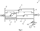
- FIG. 2 shows a schematic representation of the wiring of the clutch disc 1 with the input from the drive side, for example, from an internal combustion engine torsional vibration introduced on the input part 5 traction torque M (A) and the clutch disc 1 damped at the output part 11 derived moment M (D).
- the torsional vibration damper 3 contains the damper stages 9, 16 with the energy stores 10, 17 with the spring capacities C1, C2 and compression angles ⁇ 1, ⁇ 2 and the friction devices 34, 35 with the friction hystereses H1, H2.
- the friction device 36 is connected to the friction hysteresis H3. Due to the higher rigidity of the energy storage 10, the energy storage 17 of the damper stage 16 are active at low moments first. In acute torque changes the slip torque M (R) of the slip clutch 19 is exceeded and the centrifugal pendulum 2 decoupled.
Landscapes
- Engineering & Computer Science (AREA)
- General Engineering & Computer Science (AREA)
- Mechanical Engineering (AREA)
- Physics & Mathematics (AREA)
- Acoustics & Sound (AREA)
- Aviation & Aerospace Engineering (AREA)
- Mechanical Operated Clutches (AREA)
Description
- Die Erfindung betrifft ein Fliehkraftpendel und eine Kupplungsscheibe mit diesem mit einem um eine Drehachse verdrehbaren Pendelflansch mit mehreren über den Umfang verteilten, an dem Pendelflansch verschwenkbar aufgenommenen Pendelmassen.
- Zur Reduzierung von Torsionsschwingungen beispielsweise einer Brennkraftmaschine mit infolge über den Drehwinkel einer Kurbelwelle aufeinander folgenden Zündungen, werden Drehschwingungsdämpfer und/oder Drehschwingungstilger eingesetzt, welche auf die Erregerfrequenz optimiert sind und die Drehmomentspitzen der Torsionsschwingungen zwischenspeichern und in den Drehmomentminima der Torsionsschwingungen wieder abgeben. Als besonders vorteilhaft haben sich dabei separat oder in Kombination mit weiteren Drehschwingungsdämpfern eingesetzte drehzahladaptive Drehschwingungstilger in Form von Fliehkraftpendeln erwiesen. Hierbei werden auf einem um eine Drehachse rotierenden Teil des Torsionsschwingungssystems entlang eines Schwingwinkels gegenüber dem rotierenden Teil, beispielsweise einem Pendelflansch, mehrere über den Umfang verteilte, verschwenkbare Pendelmassen angeordnet. Diese Pendelmassen führen im Feld der Zentrifugalbeschleunigung Schwingungen auf vorgegebenen Bahnen aus, wenn sie durch Drehzahlungleichförmigkeiten wie Torsionsschwingungen angeregt werden. Durch diese Schwingungen wird der Erregerschwingung zu passenden Zeiten Energie entzogen und wieder zugeführt, so dass es zu einer Beruhigung der Erregerschwingung kommt. Da sowohl die Eigenfrequenz der Fliehkraftpendelschwingung als auch die Erregerfrequenz proportional zur Drehzahl sind, kann die Tilgerwirkung eines Fliehkraftpendels über den ganzen Frequenzbereich, also drehzahladaptiv erzielt werden.
- Derartige Fliehkraftpendel können, wie beispielsweise aus der
DE 10 2010 034 812 A1 bekannt, in Verbindung mit einem Drehschwingungsdämpfer eingesetzt werden. Beispielsweise kann ein Fliehkraftpendel in einer Kupplungsscheibe mit oder ohne Drehschwingungsdämpfer untergebracht sein, wobei der Pendelflansch des Fliehkraftpendels drehfest auf der Nabe der Kupplungsscheibe befestigt ist. Die Kupplungsscheibe mit Drehschwingungsdämpfer kann dabei im Wesentlichen eine oder mehrere in Reihe geschaltete Dämpferstufen aufweisen. Eine erste Dämpferstufe eines mehrstufigen Drehschwingungsdämpfers zeigt eine niedrige Steifigkeit und eine geringe Reibung, die bei niedrigen Drehmomenten eines Antriebsstrangs, beispielsweise in den Fahrzuständen Kriechen, Leerlauf und dergleichen wirksam ist. Eine zweite Dämpferstufe kann bei Überschreiten eines maximalen Verdrehwinkels der ersten Dämpferstufe aktiviert werden und dient der Dämpfung von höheren Drehmomenten, beispielsweise während einer Beschleunigung des Kraftfahrzeugs mit einem entsprechenden Antriebsstrang. Hierzu weist diese Dämpferstufe eine steilere Kennlinie und eine höhere Reibung auf. -
DE 10 2006 028 552 A1 offenbart eine Kupplungseinrichtung mit einer Kupplungsscheibe, die eine eine Fliehkraftpendeleinrichtung aufweisende Kupplungsnabe umfasst. - Das auf einer derartigen Kupplungsscheibe eingesetzte Fliehkraftpendel erhöht das Massenträgheitsmoment der Getriebeeingangswelle, wodurch bei hohen Momentschwankungen und kleiner Drehzahl die Dämpfungskapazität der ersten Dämpferstufe, beispielsweise beim Stilllegen der Brennkraftmaschine ohne eingelegten Gang und bei geschlossener Reibungskupplung auftreten kann. Hierdurch kann die Getriebeeingangswelle hohen Beschleunigungen mit entsprechender Geräuschbildung ausgesetzt sein.
- Aufgabe der Erfindung ist daher, ein Fliehkraftpendel insbesondere in einer Kupplungsscheibe und eine Kupplungsscheibe mit einem Fliehkraftpendel vorzuschlagen, welches bei Momentenwechseln zumindest eine Minderung von Geräuschen ermöglicht.
- Die Aufgabe wird durch ein Fliehkraftpendel mit einem um eine Drehachse verdrehbaren Pendelflansch mit mehreren über den Umfang verteilten, an dem Pendelflansch verschwenkbar aufgenommenen Pendelmassen gelöst, wobei der Pendelflansch auf einem um die Drehachse drehenden Bauteil verdrehbar aufgenommen ist und zwischen Pendelflansch und Bauteil eine Rutschkupplung wirksam angeordnet ist. Durch die Einstellung des Rutschmoments der Rutschkupplung kann das Massenträgheitsmoment des Fliehkraftpendels gezielt abgeschaltet werden, so dass beispielsweise bei Lastwechseln und dergleichen sich ein durch das Fliehkraftpendel erhöhtes Massenträgheitsmoment mit gegebenenfalls dadurch auftretenden Geräuschen wie Anschlaggeräuschen und dergleichen nicht negativ bemerkbar macht. Im Weiteren kann das Fliehkraftpendel selbst vor Beschädigung und Geräuschbildung geschützt werden, wenn dieses mittels des voreingestellten Rutschmoments der Reibungskupplung von der drehenden Welle abgekoppelt wird.
- Als besonders vorteilhaft hat sich erwiesen, wenn ein auf einer Nabe einer Kupplungsscheibe angeordnetes Fliehkraftpendel mit einer Rutschkupplung gegenüber der Nabe versehen wird. Bei geöffneter Reibungskupplung ist die Masse der Kupplungsscheibe und damit des Fliehkraftpendels ausschließlich der über die Nabe verzahnten Getriebeeingangswelle zugeordnet, so dass schnelle Momentenänderungen sich beispielsweise auf Verzahnungen im Getriebe auswirken können und Geräusche im Getriebe entstehen können. Insbesondere bei einer Ausbildung der Kupplungsscheibe mit einer als Leerlaufdämpfer eingesetzten Dämpferstufe kann diese durch das mittels der Rutschkupplung abschaltbare Fliehkraftpendel auch bei kleinen Momenten vor einem Anschlag geschützt und funktionsfähig erhalten werden.
- Die Rutschkupplung wird vorteilhafterweise durch eine mittels eines Energiespeichers, beispielsweise eine oder mehrere Federn wie Tellerfeder, vorgespannte Reibeinrichtung gebildet, wobei bevorzugt axial oder konisch ausgebildete Reibflächen an dem Pendelflansch und dem Bauteil vorgesehen sind, die unter axialer Vorspannung des Energiespeichers ein vorgegebenes Rutschmoment der Rutschkupplung ausbilden.
- Die Aufgabe wird weiterhin durch eine Kupplungsscheibe mit einem Reibbeläge tragenden Eingangsteil und einem als Nabe ausgebildeten Ausgangsteil sowie zumindest einer zwischen Eingangsteil und Ausgangsteil angeordneten Dämpferstufe und einem axial beabstandet zur zumindest einen Dämpferstufe angeordneten Fliehkraftpendel mit einem auf der Nabe zentrierten Pendelflansch und mehreren, an dem Pendelflansch über den Umfang verteilt und verschwenkbar aufgenommenen Pendelmassen gelöst, wobei zwischen Pendelflansch und Nabe eine Rutschkupplung angeordnet ist. Bevorzugt ist die Kupplungsscheibe mit zwei Dämpferstufen - einem Leerlaufdämpfer mit geringem Dämpfungsmoment und einem Hauptdämpfer mit dem über die Kupplungsscheibe unter Last zu übertragenden Moment - ausgebildet. Das Fliehkraftpendel ist dabei bezüglich seiner Wirkung dem aus Leerlauf- und Hauptdämpfer gebildeten Drehschwingungsdämpfer parallel geschaltet und wird bei auftretenden, das Rutschmoment der Rutschkupplung übersteigenden Momentenänderungen, beispielsweise während Beschleunigungen abgeschaltet. Die Rutschkupplung kann mit einem Freilauf ausgestattet wie überlagert sein, so dass die Abkopplung des Fliehkraftpendels nur in eine Drehmomentrichtung erfolgt.
- In einer bevorzugten Ausführungsform einer Kupplungsscheibe mit abkoppelbarem Fliehkraftpendel sind an der Nabe und an dem Pendelflansch einen Reibeingriff bildende Reibflächen angeordnet. Im Sinne einer kostengünstigen Ausbildung der Nabe ist hierbei an der beispielsweise gesinterten, warm umgeformten, spanend oder in ähnlicher Weise hergestellten Nabe ein die Reibfläche enthaltender Ringbund mit einer Reibfläche einteilig angearbeitet.
- Die Vorspannung der Reibflächen zwischen Nabe und Pendelflansch erfolgt mittels eines Energiespeichers der axial zwischen der Nabe und dem Pendelflansch verzahnt ist. Zur axialen Abstützung des Energiespeichers ist bevorzugt ein Stützbund vorgesehen, der einteilig an der Nabe angearbeitet ist, wobei in bevorzugter Weise der Pendelflansch zuerst auf der Nabe gegen einen die Reibfläche enthaltenden Anschlag wie Ringbund und anschließend der Energiespeicher, beispielsweise eine Tellerfeder, aufgebracht und zentriert werden und anschließend beispielsweise durch Verstemmen, Rollieren oder dergleichen der Stützbund, der ringförmig oder aus über den Umfang verteilt angeordneten Stützsegmenten gebildet sein kann, unter Einstellung der Vorspannung des Pendelflanschs zur Nabe hergestellt wird.
- In vorteilhafter Weise kann der bevorzugt aus einer Tellerfeder gebildete Energiespeicher an dem Pendelflansch drehfest eingehängt sein und gegenüber dem dann in bevorzugter Weise ringförmig ausgebildeten Stützbund eine weitere Reibstelle bei aktivierter Rutschkupplung bilden.
- Die Erfindung wird anhand des in den
Figuren 1 und2 dargestellten Ausführungsbeispiels näher erläutert. Dabei zeigen: - Figur 1
- einen Teilschnitt durch eine Kupplungsscheibe mit einem mittels Rutschkupplung abkoppelbaren Fliehkraftpendel
und - Figur 2
- ein Prinzipschaltbild der Kupplungsscheibe der
Figur 1 mit zweistufigem Drehschwingungsdämpfer und parallel geschaltetem Fliehkraftpendel. - Die
Figur 1 zeigt den oberen Teil der um die Drehachse 4 angeordneten Kupplungsscheibe 1 mit dem Fliehkraftpendel 2 und dem Drehschwingungsdämpfer 3. Das Eingangsteil 5 der Kupplungsscheibe 1 ist aus dem die Reibbeläge 6 tragenden, mit dem Scheibenteil 8 die Energiespeicher 10 der Dämpferstufe 9 des Hauptdämpfers beaufschlagenden Scheibenteil 7, das Ausgangsteil 11 durch die Nabe 13 gebildet. Der Flansch 12 ist an der Verzahnung 15 mit Verdrehspiel mit dem als Nabe 13 ausgebildeten Bauteil 14 verzahnt, über dessen Verdrehwinkel die zweite Dämpferstufe 16 des Leerlaufdämpfers, deren Energiespeicher 17 zwischen dem Flansch 12 und dem direkt mit der Nabe 13 verzahnten Mitnehmer 18 verspannt sind. Die Energiespeicher 10 werden zwischen dem Eingangsteil 5 und dem Mitnehmer 18 verspannt. - Das Fliehkraftpendel 2 ist auf dem Bauteil 14 wie Nabe 13 mittels der Rutschkupplung 19 nach Überwindung eines durch die Rutschkupplung 19 bereitgestellten Rutschmoments verdrehbar aufgenommen. Hierzu ist der Pendelflansch 20, an dem beidseitig über den Umfang verteilt die Pendelmassen 21 mittels der in den Ausschnitten 22, 23 des Pendelflanschs 20 und der Pendelmassen 21 abwälzende Rollen 24 verschwenkbar aufgenommen sind, unter Bildung eines Reibeingriffs mittels der Reibfläche 25 gegen die Reibfläche 26 des an der Nabe 13 einteilig ausgebildeten Ringbunds 27 axial vorgespannt. Die Vorspannung übernimmt der als Tellerfeder 29 ausgebildete Energiespeicher 28, der sich an dem an der Nabe 13 angearbeiteten Lagerbund 30 abstützt und mittels der Finger 31 in die Ausschnitte 32 eingreift und damit drehfest mit dem Pendelflansch 20 verbunden ist und entlang des Lagerbunds 30 bei überwundenem Rutschmoment der Rutschkupplung 19 gleitet.
- Das Fliehkraftpendel 2 ist dem Drehschwingungsdämpfer 3 parallel geschaltet und tilgt bei nicht aktiver Rutschkupplung 19 drehzahladaptiv Schwingungen. Bei geöffneter Reibungskupplung ist das Massenträgheitsmoment des Fliehkraftpendels 2 an die mittels der Innenverzahnung 33 drehschlüssig mit der Nabe 13 verbundene Getriebeeingangswelle gekoppelt. Um einerseits die Wirksamkeit der zweiten Dämpferstufe 16 des Drehschwingungsdämpfers 3 zu erhalten und andererseits durch das Massenträgheitsmoment des Fliehkraftpendels 2 in dem Getriebe induzierte Geräusche zu unterbinden, wird das Fliehkraftpendel 2 bei die Momentenkapazität der Dämpfungsstufe 16 überschreitenden Massenträgheitsmomenten mittels der Rutschkupplung 19 angekoppelt.
-
Figur 2 zeigt in schematischer Darstellung die Beschaltung der Kupplungsscheibe 1 mit dem von der Antriebsseite, beispielsweise von einer Brennkraftmaschine drehschwingungsbehaftet auf das Eingangsteil 5 eingebrachten Zugmoment M(A) und dem die Kupplungsscheibe 1 bedämpft an dem Ausgangsteil 11 ausgeleiteten Moment M(D). Zwischen Eingangsteil 5 und Ausgangsteil 11 sind der Drehschwingungsdämpfer 3 und parallel hierzu über die Nabe 13 (Figur 1 ) das mittels der Rutschkupplung 19 abkoppelbare Fliehkraftpendel 2 wirksam. Der Drehschwingungsdämpfer 3 enthält die Dämpferstufen 9, 16 mit den Energiespeichern 10, 17 mit den Federkapazitäten C1, C2 und Kompressionswinkeln α1, α2 sowie die Reibeinrichtungen 34, 35 mit den Reibhysteresen H1, H2. Über den gesamten Verdrehwinkel zwischen Eingangsteil 5 und Nabe 13 ist die Reibeinrichtung 36 mit der Reibhysterese H3 geschaltet. Aufgrund der höheren Steifigkeit der Energiespeicher 10 sind bei geringen Momenten zuerst die Energiespeicher 17 der Dämpferstufe 16 aktiv. Bei akuten Momentenänderungen wird das Rutschmoment M(R) der Rutschkupplung 19 überschritten und das Fliehkraftpendel 2 abgekoppelt. -
- 1
- Kupplungsscheibe
- 2
- Fliehkraftpendel
- 3
- Drehschwingungsdämpfer
- 4
- Drehachse
- 5
- Eingangsteil
- 6
- Reibbelag
- 7
- Scheibenteil
- 8
- Scheibenteil
- 9
- Dämpferstufe
- 10
- Energiespeicher
- 11
- Ausgangsteil
- 12
- Flansch
- 13
- Nabe
- 14
- Bauteil
- 15
- Verzahnung
- 16
- Dämpferstufe
- 17
- Energiespeicher
- 18
- Mitnehmer
- 19
- Rutschkupplung
- 20
- Pendelflansch
- 21
- Pendelmasse
- 22
- Ausschnitt
- 23
- Ausschnitt
- 24
- Rolle
- 25
- Reibfläche
- 26
- Reibfläche
- 27
- Ringbund
- 28
- Energiespeicher
- 29
- Tellerfeder
- 30
- Lagerbund
- 31
- Finger
- 32
- Ausschnitt
- 33
- Innenverzahnung
- 34
- Reibeinrichtung
- 35
- Reibeinrichtung
- 36
- Reibeinrichtung
- C1
- Federkapazität
- C2
- Federkapazität
- H1
- Reibhysterese
- H2
- Reibhysterese
- H3
- Reibhysterese
- M(A)
- Zugmoment
- M(D)
- Moment
- M(R)
- Rutschmoment
- α1
- Kompressionswinkel
- α2
- Kompressionswinkel
Claims (10)
- Fliehkraftpendel (2) mit einem um eine Drehachse (4) verdrehbaren Pendelflansch (20) mit mehreren über den Umfang verteilten, an dem Pendelflansch (20) verschwenkbar aufgenommenen Pendelmassen (21), dadurch gekennzeichnet, dass der Pendelflansch (20) auf einem um die Drehachse (4) drehenden Bauteil (14) verdrehbar aufgenommen ist und zwischen Pendelflansch (20) und Bauteil (14) eine Rutschkupplung (19) wirksam angeordnet ist.
- Fliehkraftpendel (2) nach Anspruch 1, dadurch gekennzeichnet, dass das Bauteil (14) aus einer Nabe (13) einer Kupplungsscheibe (1) gebildet ist.
- Fliehkraftpendel (2) nach Anspruch 1 oder 2, dadurch gekennzeichnet, dass zwischen Pendelflansch (20) und Bauteil (14) eine die Rutschkupplung bildende, federbelastete Reibeinrichtung ausgebildet ist.
- Kupplungsscheibe (1) mit einem Reibbeläge (6) tragenden Eingangsteil (5) und einem als Nabe (13) ausgebildeten Ausgangsteil (11) sowie zumindest einer zwischen Eingangsteil (5) und Ausgangsteil (11) angeordneten Dämpferstufe (9, 16) und einem axial beabstandet zur zumindest einen Dämpferstufe (9, 16) angeordneten Fliehkraftpendel (2) mit einem auf der Nabe (13) zentrierten und verdrehbar aufgenommenen Pendelflansch (20) und mehreren, an dem Pendelflansch (20) über den Umfang verteilt und verschwenkbar aufgenommenen Pendelmassen (21), dadurch gekennzeichnet, dass zwischen Pendelflansch (20) und Nabe (13) eine Rutschkupplung (19) angeordnet ist.
- Kupplungsscheibe (1) nach Anspruch 4, dadurch gekennzeichnet, dass an der Nabe (13) und an dem Pendelflansch (20) die Rutschkupplung bildende, einen Reibeingriff bildende Reibflächen (25, 26) angeordnet sind.
- Kupplungsscheibe (1) nach Anspruch 5, dadurch gekennzeichnet, dass an der Nabe (13) ein Ringbund (27) mit einer der Reibflächen (26) einteilig angearbeitet ist.
- Kupplungsscheibe (1) nach Anspruch 5 oder 6, dadurch gekennzeichnet, dass der Pendelflansch (20) entgegen der Wirkung eines Energiespeichers (28) gegen die Nabe (13) vorgespannt ist.
- Kupplungsscheibe (1) nach Anspruch 7, dadurch gekennzeichnet, dass sich der Energiespeicher (28) an einem an der Nabe (13) einteilig angearbeiteten Lagerbund (30) abstützt.
- Kupplungsscheibe (1) nach Anspruch 7 oder 8, dadurch gekennzeichnet, dass der Energiespeicher (28) drehfest in den Pendelflansch (20) eingehängt ist.
- Kupplungsscheibe (1) nach einem der Ansprüche 7 bis 9, dadurch gekennzeichnet, dass der Energiespeicher (28) eine Tellerfeder (29) ist.
Applications Claiming Priority (2)
| Application Number | Priority Date | Filing Date | Title |
|---|---|---|---|
| DE102011082389 | 2011-09-09 | ||
| PCT/DE2012/000841 WO2013034125A1 (de) | 2011-09-09 | 2012-08-21 | Fliehkraftpendel und kupplungsscheibe mit diesem |
Publications (3)
| Publication Number | Publication Date |
|---|---|
| EP2753847A1 EP2753847A1 (de) | 2014-07-16 |
| EP2753847B1 true EP2753847B1 (de) | 2019-01-02 |
| EP2753847B2 EP2753847B2 (de) | 2024-12-04 |
Family
ID=46934354
Family Applications (1)
| Application Number | Title | Priority Date | Filing Date |
|---|---|---|---|
| EP12765984.5A Active EP2753847B2 (de) | 2011-09-09 | 2012-08-21 | Fliehkraftpendel und kupplungsscheibe mit diesem |
Country Status (5)
| Country | Link |
|---|---|
| US (1) | US9574615B2 (de) |
| EP (1) | EP2753847B2 (de) |
| CN (1) | CN103917801B (de) |
| DE (2) | DE102012214813A1 (de) |
| WO (1) | WO2013034125A1 (de) |
Families Citing this family (25)
| Publication number | Priority date | Publication date | Assignee | Title |
|---|---|---|---|---|
| JP6149415B2 (ja) * | 2013-02-06 | 2017-06-21 | アイシン精機株式会社 | 動力伝達装置 |
| DE102014208563A1 (de) | 2013-06-05 | 2014-12-11 | Schaeffler Technologies Gmbh & Co. Kg | Kupplungsscheibeneinrichtung und Reibungskupplung mit entsprechender Kupplungsscheibeneinrichtung |
| DE112014004477A5 (de) | 2013-09-26 | 2016-06-02 | Schaeffler Technologies AG & Co. KG | Drehmomentübertragungseinrichtung |
| DE102014224091A1 (de) | 2013-12-18 | 2015-06-18 | Schaeffler Technologies AG & Co. KG | Fliehkraftpendel |
| FR3018877B1 (fr) * | 2014-03-20 | 2018-04-27 | Valeo Embrayages | Dispositif d'embrayage, notamment pour vehicule automobile |
| DE102014219271A1 (de) * | 2014-09-24 | 2016-03-24 | Schaeffler Technologies AG & Co. KG | Kupplungsscheibe mit einem Drehschwingungsdämpfer |
| DE102014225605A1 (de) * | 2014-12-11 | 2016-06-16 | Zf Friedrichshafen Ag | Kupplungsscheibe |
| DE102015204027A1 (de) * | 2015-03-06 | 2016-09-08 | Schaeffler Technologies AG & Co. KG | Fliehkraftpendeleinrichtung mit Druckfedern |
| US9328774B1 (en) | 2015-05-07 | 2016-05-03 | Borgwarner Inc. | Flat spring torsional vibration dampers |
| DE102015209998B4 (de) | 2015-06-01 | 2025-02-06 | Schaeffler Technologies AG & Co. KG | Reibungskupplung mit Fliehkraftpendel |
| FR3039613B1 (fr) * | 2015-07-30 | 2018-03-02 | Valeo Embrayages | Dispositif d'amortissement d'oscillations de torsion |
| DE102016219678A1 (de) * | 2015-10-12 | 2017-04-13 | Schaeffler Technologies AG & Co. KG | Drehmomentübertragungseinrichtung |
| FR3047529A1 (fr) * | 2016-02-04 | 2017-08-11 | Valeo Embrayages | Dispositif d'amortissement pendulaire |
| FR3051859B1 (fr) | 2016-05-24 | 2020-04-17 | Valeo Embrayages | Dispositif d'amortissement pendulaire |
| FR3052513B1 (fr) * | 2016-06-08 | 2019-04-12 | Valeo Embrayages | Disque de friction avec dispositif d'amortissement pendulaire |
| FR3052514B1 (fr) * | 2016-06-08 | 2018-06-08 | Valeo Embrayages | Disque de friction pour embrayage avec dispositif d'amortissement pendulaire |
| JP2018013144A (ja) * | 2016-07-19 | 2018-01-25 | 株式会社エクセディ | 動吸振器 |
| FR3057313B1 (fr) * | 2016-10-06 | 2019-11-01 | Valeo Embrayages | Composant pour systeme de transmission de vehicule |
| FR3057928B1 (fr) * | 2016-10-20 | 2020-01-10 | Valeo Embrayages | Dispositif d'amortissement d'oscillations de torsion |
| JP6827311B2 (ja) | 2016-12-12 | 2021-02-10 | 株式会社エクセディ | ダンパ装置 |
| FR3070462B1 (fr) * | 2017-08-29 | 2020-07-10 | Valeo Embrayages | Amortisseur de torsion |
| CN110345171B (zh) * | 2018-04-08 | 2022-11-22 | 舍弗勒技术股份两合公司 | 具有离心摆的离合器盘和离合器装置 |
| FR3096424B1 (fr) * | 2019-05-23 | 2021-05-28 | Valeo Embrayages | Dispositif de transmission équipé d’au moins un premier amortisseur et d’un absorbeur dynamique de vibration |
| DE102020117763A1 (de) | 2020-07-06 | 2022-01-13 | Schaeffler Technologies AG & Co. KG | Torsionsschwingungsdämpfer |
| DE102020125360B4 (de) | 2020-09-29 | 2022-08-04 | Schaeffler Technologies AG & Co. KG | Anordnung |
Citations (8)
| Publication number | Priority date | Publication date | Assignee | Title |
|---|---|---|---|---|
| US6068098A (en) | 1997-07-11 | 2000-05-30 | Exedy Corporation | Dynamic damper and coupling mechanism |
| EP1780434A2 (de) | 2005-10-29 | 2007-05-02 | LuK Lamellen und Kupplungsbau Beteiligungs KG | Kupplungseinrichtung |
| DE102006028552A1 (de) * | 2005-10-29 | 2007-05-03 | Luk Lamellen Und Kupplungsbau Beteiligungs Kg | Kupplungseinrichtung |
| DE102009033864A1 (de) | 2008-07-31 | 2010-02-04 | Luk Lamellen Und Kupplungsbau Beteiligungs Kg | Zweimassenschwungrad |
| WO2010028620A1 (de) | 2008-09-11 | 2010-03-18 | Luk Lamellen Und Kupplungsbau Beteiligungs Kg | Drehmomentübertragungseinrichtung |
| DE102009042837A1 (de) | 2008-10-16 | 2010-04-22 | Luk Lamellen Und Kupplungsbau Beteiligungs Kg | Hydrodynamischer Drehmomentwandler |
| DE102010049929A1 (de) * | 2009-11-17 | 2011-05-19 | Schaeffler Technologies Gmbh & Co. Kg | Reibungskupplung mit einer Kupplungsscheibe zur Übertragung von Drehmomenten |
| EP2685127A1 (de) | 2011-03-11 | 2014-01-15 | Toyota Jidosha Kabushiki Kaisha | Schwingungsdämpfungsvorrichtung |
Family Cites Families (5)
| Publication number | Priority date | Publication date | Assignee | Title |
|---|---|---|---|---|
| JPS60133234U (ja) * | 1984-02-17 | 1985-09-05 | 株式会社 大金製作所 | ダンパ−デイスク |
| US5560267A (en) * | 1994-06-21 | 1996-10-01 | Borg-Warner Automotive, Inc. | Camshaft vibration damper |
| DE19613574C2 (de) * | 1996-04-04 | 2003-08-21 | Zf Sachs Ag | Drehschwingungsdämpfer |
| DE112009001493B3 (de) * | 2008-07-04 | 2019-04-04 | Schaeffler Technologies AG & Co. KG | Hydrodynamischer Drehmomentwandler |
| DE102010034812B4 (de) | 2009-09-17 | 2018-06-21 | Schaeffler Technologies AG & Co. KG | Schwungrad und Reibungskupplung |
-
2012
- 2012-08-21 CN CN201280043933.8A patent/CN103917801B/zh active Active
- 2012-08-21 DE DE102012214813A patent/DE102012214813A1/de not_active Withdrawn
- 2012-08-21 EP EP12765984.5A patent/EP2753847B2/de active Active
- 2012-08-21 WO PCT/DE2012/000841 patent/WO2013034125A1/de not_active Ceased
- 2012-08-21 DE DE112012003758.8T patent/DE112012003758B4/de not_active Expired - Fee Related
-
2014
- 2014-03-07 US US14/200,627 patent/US9574615B2/en active Active
Patent Citations (8)
| Publication number | Priority date | Publication date | Assignee | Title |
|---|---|---|---|---|
| US6068098A (en) | 1997-07-11 | 2000-05-30 | Exedy Corporation | Dynamic damper and coupling mechanism |
| EP1780434A2 (de) | 2005-10-29 | 2007-05-02 | LuK Lamellen und Kupplungsbau Beteiligungs KG | Kupplungseinrichtung |
| DE102006028552A1 (de) * | 2005-10-29 | 2007-05-03 | Luk Lamellen Und Kupplungsbau Beteiligungs Kg | Kupplungseinrichtung |
| DE102009033864A1 (de) | 2008-07-31 | 2010-02-04 | Luk Lamellen Und Kupplungsbau Beteiligungs Kg | Zweimassenschwungrad |
| WO2010028620A1 (de) | 2008-09-11 | 2010-03-18 | Luk Lamellen Und Kupplungsbau Beteiligungs Kg | Drehmomentübertragungseinrichtung |
| DE102009042837A1 (de) | 2008-10-16 | 2010-04-22 | Luk Lamellen Und Kupplungsbau Beteiligungs Kg | Hydrodynamischer Drehmomentwandler |
| DE102010049929A1 (de) * | 2009-11-17 | 2011-05-19 | Schaeffler Technologies Gmbh & Co. Kg | Reibungskupplung mit einer Kupplungsscheibe zur Übertragung von Drehmomenten |
| EP2685127A1 (de) | 2011-03-11 | 2014-01-15 | Toyota Jidosha Kabushiki Kaisha | Schwingungsdämpfungsvorrichtung |
Also Published As
| Publication number | Publication date |
|---|---|
| WO2013034125A1 (de) | 2013-03-14 |
| US9574615B2 (en) | 2017-02-21 |
| DE102012214813A1 (de) | 2013-03-14 |
| EP2753847B2 (de) | 2024-12-04 |
| EP2753847A1 (de) | 2014-07-16 |
| CN103917801B (zh) | 2015-12-09 |
| CN103917801A (zh) | 2014-07-09 |
| DE112012003758B4 (de) | 2022-06-30 |
| US20140182993A1 (en) | 2014-07-03 |
| DE112012003758A5 (de) | 2014-08-28 |
Similar Documents
| Publication | Publication Date | Title |
|---|---|---|
| EP2753847B2 (de) | Fliehkraftpendel und kupplungsscheibe mit diesem | |
| EP3198169B1 (de) | Kupplungsscheibe mit einem drehschwingungsdämpfer | |
| DE102011076790A1 (de) | Antriebssystem für ein Fahrzeug | |
| DE102005059030A1 (de) | Triebrad eines Nebenaggregatezugs eines Verbrennungsmotors | |
| DE102015201030B4 (de) | Antriebsstrang für ein Kraftfahrzeug | |
| DE102009050353A1 (de) | Drehschwingungsdämpfer mit separater Trägerscheibe für Pendelmassen | |
| DE102020127458A1 (de) | Pendelwippendämpfer mit einstellbarer Reibeinrichtung; sowie Hybridantriebsstrang | |
| DE102013200408A1 (de) | Nasse Reibkupplung mit integriertem Dämpfersystem | |
| WO2016091260A1 (de) | Zweimassenschwungrad mit zusatzmasse | |
| DE102019118504A1 (de) | Drehschwingungsdämpfer | |
| DE102014204153A1 (de) | Drehschwingungsdämpfer | |
| DE102016218386A1 (de) | Schwingungsisolationseinrichtung | |
| WO2015188821A1 (de) | Drehschwingungsdämpfer | |
| DE102009049879A1 (de) | Schwingungstilger zur Dämpfung von Drehschwingungen im Antriebsstrang eines Kraftfahrzeugs | |
| DE102016201099A1 (de) | Fliehkraftpendel | |
| DE102014214669A1 (de) | Drehschwingungsdämpfer | |
| DE1082080B (de) | Maschine mit einer von hin- und her-gehenden Kolben gedrehten Kurbelwelle, die mit einer torsionsfedernden Antriebswelle und einer Daempfermasse verbunden ist | |
| DE102021110542A1 (de) | Ausgangsscheibe für einen Drehschwingungsdämpfer | |
| DE102011014004A1 (de) | Drehmomentübertragungseinrichtung | |
| DE102015224762A1 (de) | Drehschwingungsdämpfer | |
| DE102016211094A1 (de) | Einmassenschwungrad mit Drehschwingungsdämpfer und Fliehkraftpendel | |
| DE102020107702B4 (de) | Hybridantriebsstrang | |
| DE102019109245A1 (de) | Schwungradanordnung und Antriebsstrang | |
| DE102018109072A1 (de) | Kupplungsscheibe für eine Reibkupplung mit Fliehkraftpendel | |
| DE102020129741A1 (de) | Drehschwingungsdämpfer |
Legal Events
| Date | Code | Title | Description |
|---|---|---|---|
| PUAI | Public reference made under article 153(3) epc to a published international application that has entered the european phase |
Free format text: ORIGINAL CODE: 0009012 |
|
| 17P | Request for examination filed |
Effective date: 20140409 |
|
| AK | Designated contracting states |
Kind code of ref document: A1 Designated state(s): AL AT BE BG CH CY CZ DE DK EE ES FI FR GB GR HR HU IE IS IT LI LT LU LV MC MK MT NL NO PL PT RO RS SE SI SK SM TR |
|
| DAX | Request for extension of the european patent (deleted) | ||
| RAP1 | Party data changed (applicant data changed or rights of an application transferred) |
Owner name: SCHAEFFLER TECHNOLOGIES AG & CO. KG |
|
| RIN1 | Information on inventor provided before grant (corrected) |
Inventor name: HEPPERLE, WALTER Inventor name: LEHMANN, STEFFEN Inventor name: RUSCH, ALAIN |
|
| REG | Reference to a national code |
Ref country code: DE Ref legal event code: R079 Ref document number: 502012014104 Country of ref document: DE Free format text: PREVIOUS MAIN CLASS: F16F0015140000 Ipc: F16F0015120000 |
|
| RIC1 | Information provided on ipc code assigned before grant |
Ipc: F16D 13/38 20060101ALI20180608BHEP Ipc: F16F 15/12 20060101AFI20180608BHEP Ipc: F16F 15/129 20060101ALI20180608BHEP Ipc: F16F 15/14 20060101ALI20180608BHEP Ipc: F16D 3/12 20060101ALI20180608BHEP |
|
| GRAP | Despatch of communication of intention to grant a patent |
Free format text: ORIGINAL CODE: EPIDOSNIGR1 |
|
| STAA | Information on the status of an ep patent application or granted ep patent |
Free format text: STATUS: GRANT OF PATENT IS INTENDED |
|
| INTG | Intention to grant announced |
Effective date: 20180815 |
|
| GRAS | Grant fee paid |
Free format text: ORIGINAL CODE: EPIDOSNIGR3 |
|
| GRAA | (expected) grant |
Free format text: ORIGINAL CODE: 0009210 |
|
| STAA | Information on the status of an ep patent application or granted ep patent |
Free format text: STATUS: THE PATENT HAS BEEN GRANTED |
|
| AK | Designated contracting states |
Kind code of ref document: B1 Designated state(s): AL AT BE BG CH CY CZ DE DK EE ES FI FR GB GR HR HU IE IS IT LI LT LU LV MC MK MT NL NO PL PT RO RS SE SI SK SM TR |
|
| REG | Reference to a national code |
Ref country code: GB Ref legal event code: FG4D Free format text: NOT ENGLISH |
|
| REG | Reference to a national code |
Ref country code: CH Ref legal event code: EP Ref country code: AT Ref legal event code: REF Ref document number: 1084780 Country of ref document: AT Kind code of ref document: T Effective date: 20190115 |
|
| REG | Reference to a national code |
Ref country code: DE Ref legal event code: R096 Ref document number: 502012014104 Country of ref document: DE |
|
| REG | Reference to a national code |
Ref country code: IE Ref legal event code: FG4D Free format text: LANGUAGE OF EP DOCUMENT: GERMAN |
|
| REG | Reference to a national code |
Ref country code: NL Ref legal event code: MP Effective date: 20190102 |
|
| REG | Reference to a national code |
Ref country code: LT Ref legal event code: MG4D |
|
| PG25 | Lapsed in a contracting state [announced via postgrant information from national office to epo] |
Ref country code: NL Free format text: LAPSE BECAUSE OF FAILURE TO SUBMIT A TRANSLATION OF THE DESCRIPTION OR TO PAY THE FEE WITHIN THE PRESCRIBED TIME-LIMIT Effective date: 20190102 |
|
| PG25 | Lapsed in a contracting state [announced via postgrant information from national office to epo] |
Ref country code: LT Free format text: LAPSE BECAUSE OF FAILURE TO SUBMIT A TRANSLATION OF THE DESCRIPTION OR TO PAY THE FEE WITHIN THE PRESCRIBED TIME-LIMIT Effective date: 20190102 Ref country code: FI Free format text: LAPSE BECAUSE OF FAILURE TO SUBMIT A TRANSLATION OF THE DESCRIPTION OR TO PAY THE FEE WITHIN THE PRESCRIBED TIME-LIMIT Effective date: 20190102 Ref country code: PT Free format text: LAPSE BECAUSE OF FAILURE TO SUBMIT A TRANSLATION OF THE DESCRIPTION OR TO PAY THE FEE WITHIN THE PRESCRIBED TIME-LIMIT Effective date: 20190502 Ref country code: ES Free format text: LAPSE BECAUSE OF FAILURE TO SUBMIT A TRANSLATION OF THE DESCRIPTION OR TO PAY THE FEE WITHIN THE PRESCRIBED TIME-LIMIT Effective date: 20190102 Ref country code: SE Free format text: LAPSE BECAUSE OF FAILURE TO SUBMIT A TRANSLATION OF THE DESCRIPTION OR TO PAY THE FEE WITHIN THE PRESCRIBED TIME-LIMIT Effective date: 20190102 Ref country code: NO Free format text: LAPSE BECAUSE OF FAILURE TO SUBMIT A TRANSLATION OF THE DESCRIPTION OR TO PAY THE FEE WITHIN THE PRESCRIBED TIME-LIMIT Effective date: 20190402 Ref country code: PL Free format text: LAPSE BECAUSE OF FAILURE TO SUBMIT A TRANSLATION OF THE DESCRIPTION OR TO PAY THE FEE WITHIN THE PRESCRIBED TIME-LIMIT Effective date: 20190102 |
|
| REG | Reference to a national code |
Ref country code: DE Ref legal event code: R026 Ref document number: 502012014104 Country of ref document: DE |
|
| PLBI | Opposition filed |
Free format text: ORIGINAL CODE: 0009260 |
|
| PG25 | Lapsed in a contracting state [announced via postgrant information from national office to epo] |
Ref country code: IS Free format text: LAPSE BECAUSE OF FAILURE TO SUBMIT A TRANSLATION OF THE DESCRIPTION OR TO PAY THE FEE WITHIN THE PRESCRIBED TIME-LIMIT Effective date: 20190502 Ref country code: LV Free format text: LAPSE BECAUSE OF FAILURE TO SUBMIT A TRANSLATION OF THE DESCRIPTION OR TO PAY THE FEE WITHIN THE PRESCRIBED TIME-LIMIT Effective date: 20190102 Ref country code: HR Free format text: LAPSE BECAUSE OF FAILURE TO SUBMIT A TRANSLATION OF THE DESCRIPTION OR TO PAY THE FEE WITHIN THE PRESCRIBED TIME-LIMIT Effective date: 20190102 Ref country code: GR Free format text: LAPSE BECAUSE OF FAILURE TO SUBMIT A TRANSLATION OF THE DESCRIPTION OR TO PAY THE FEE WITHIN THE PRESCRIBED TIME-LIMIT Effective date: 20190403 Ref country code: BG Free format text: LAPSE BECAUSE OF FAILURE TO SUBMIT A TRANSLATION OF THE DESCRIPTION OR TO PAY THE FEE WITHIN THE PRESCRIBED TIME-LIMIT Effective date: 20190402 Ref country code: RS Free format text: LAPSE BECAUSE OF FAILURE TO SUBMIT A TRANSLATION OF THE DESCRIPTION OR TO PAY THE FEE WITHIN THE PRESCRIBED TIME-LIMIT Effective date: 20190102 |
|
| 26 | Opposition filed |
Opponent name: ZF FRIEDRICHSHAFEN AG Effective date: 20190807 |
|
| PLAX | Notice of opposition and request to file observation + time limit sent |
Free format text: ORIGINAL CODE: EPIDOSNOBS2 |
|
| PG25 | Lapsed in a contracting state [announced via postgrant information from national office to epo] |
Ref country code: RO Free format text: LAPSE BECAUSE OF FAILURE TO SUBMIT A TRANSLATION OF THE DESCRIPTION OR TO PAY THE FEE WITHIN THE PRESCRIBED TIME-LIMIT Effective date: 20190102 Ref country code: CZ Free format text: LAPSE BECAUSE OF FAILURE TO SUBMIT A TRANSLATION OF THE DESCRIPTION OR TO PAY THE FEE WITHIN THE PRESCRIBED TIME-LIMIT Effective date: 20190102 Ref country code: SK Free format text: LAPSE BECAUSE OF FAILURE TO SUBMIT A TRANSLATION OF THE DESCRIPTION OR TO PAY THE FEE WITHIN THE PRESCRIBED TIME-LIMIT Effective date: 20190102 Ref country code: IT Free format text: LAPSE BECAUSE OF FAILURE TO SUBMIT A TRANSLATION OF THE DESCRIPTION OR TO PAY THE FEE WITHIN THE PRESCRIBED TIME-LIMIT Effective date: 20190102 Ref country code: EE Free format text: LAPSE BECAUSE OF FAILURE TO SUBMIT A TRANSLATION OF THE DESCRIPTION OR TO PAY THE FEE WITHIN THE PRESCRIBED TIME-LIMIT Effective date: 20190102 Ref country code: DK Free format text: LAPSE BECAUSE OF FAILURE TO SUBMIT A TRANSLATION OF THE DESCRIPTION OR TO PAY THE FEE WITHIN THE PRESCRIBED TIME-LIMIT Effective date: 20190102 Ref country code: AL Free format text: LAPSE BECAUSE OF FAILURE TO SUBMIT A TRANSLATION OF THE DESCRIPTION OR TO PAY THE FEE WITHIN THE PRESCRIBED TIME-LIMIT Effective date: 20190102 |
|
| PG25 | Lapsed in a contracting state [announced via postgrant information from national office to epo] |
Ref country code: SM Free format text: LAPSE BECAUSE OF FAILURE TO SUBMIT A TRANSLATION OF THE DESCRIPTION OR TO PAY THE FEE WITHIN THE PRESCRIBED TIME-LIMIT Effective date: 20190102 |
|
| PLBB | Reply of patent proprietor to notice(s) of opposition received |
Free format text: ORIGINAL CODE: EPIDOSNOBS3 |
|
| PG25 | Lapsed in a contracting state [announced via postgrant information from national office to epo] |
Ref country code: SI Free format text: LAPSE BECAUSE OF FAILURE TO SUBMIT A TRANSLATION OF THE DESCRIPTION OR TO PAY THE FEE WITHIN THE PRESCRIBED TIME-LIMIT Effective date: 20190102 |
|
| PG25 | Lapsed in a contracting state [announced via postgrant information from national office to epo] |
Ref country code: TR Free format text: LAPSE BECAUSE OF FAILURE TO SUBMIT A TRANSLATION OF THE DESCRIPTION OR TO PAY THE FEE WITHIN THE PRESCRIBED TIME-LIMIT Effective date: 20190102 |
|
| GBPC | Gb: european patent ceased through non-payment of renewal fee |
Effective date: 20190821 |
|
| PG25 | Lapsed in a contracting state [announced via postgrant information from national office to epo] |
Ref country code: MC Free format text: LAPSE BECAUSE OF FAILURE TO SUBMIT A TRANSLATION OF THE DESCRIPTION OR TO PAY THE FEE WITHIN THE PRESCRIBED TIME-LIMIT Effective date: 20190102 Ref country code: LI Free format text: LAPSE BECAUSE OF NON-PAYMENT OF DUE FEES Effective date: 20190831 Ref country code: LU Free format text: LAPSE BECAUSE OF NON-PAYMENT OF DUE FEES Effective date: 20190821 Ref country code: CH Free format text: LAPSE BECAUSE OF NON-PAYMENT OF DUE FEES Effective date: 20190831 |
|
| REG | Reference to a national code |
Ref country code: BE Ref legal event code: MM Effective date: 20190831 |
|
| PG25 | Lapsed in a contracting state [announced via postgrant information from national office to epo] |
Ref country code: IE Free format text: LAPSE BECAUSE OF NON-PAYMENT OF DUE FEES Effective date: 20190821 |
|
| PG25 | Lapsed in a contracting state [announced via postgrant information from national office to epo] |
Ref country code: GB Free format text: LAPSE BECAUSE OF NON-PAYMENT OF DUE FEES Effective date: 20190821 Ref country code: BE Free format text: LAPSE BECAUSE OF NON-PAYMENT OF DUE FEES Effective date: 20190831 |
|
| REG | Reference to a national code |
Ref country code: AT Ref legal event code: MM01 Ref document number: 1084780 Country of ref document: AT Kind code of ref document: T Effective date: 20190821 |
|
| PG25 | Lapsed in a contracting state [announced via postgrant information from national office to epo] |
Ref country code: AT Free format text: LAPSE BECAUSE OF NON-PAYMENT OF DUE FEES Effective date: 20190821 |
|
| PG25 | Lapsed in a contracting state [announced via postgrant information from national office to epo] |
Ref country code: CY Free format text: LAPSE BECAUSE OF FAILURE TO SUBMIT A TRANSLATION OF THE DESCRIPTION OR TO PAY THE FEE WITHIN THE PRESCRIBED TIME-LIMIT Effective date: 20190102 |
|
| PG25 | Lapsed in a contracting state [announced via postgrant information from national office to epo] |
Ref country code: MT Free format text: LAPSE BECAUSE OF FAILURE TO SUBMIT A TRANSLATION OF THE DESCRIPTION OR TO PAY THE FEE WITHIN THE PRESCRIBED TIME-LIMIT Effective date: 20190102 Ref country code: HU Free format text: LAPSE BECAUSE OF FAILURE TO SUBMIT A TRANSLATION OF THE DESCRIPTION OR TO PAY THE FEE WITHIN THE PRESCRIBED TIME-LIMIT; INVALID AB INITIO Effective date: 20120821 |
|
| PLAB | Opposition data, opponent's data or that of the opponent's representative modified |
Free format text: ORIGINAL CODE: 0009299OPPO |
|
| R26 | Opposition filed (corrected) |
Opponent name: ZF FRIEDRICHSHAFEN AG Effective date: 20190807 |
|
| PG25 | Lapsed in a contracting state [announced via postgrant information from national office to epo] |
Ref country code: MK Free format text: LAPSE BECAUSE OF FAILURE TO SUBMIT A TRANSLATION OF THE DESCRIPTION OR TO PAY THE FEE WITHIN THE PRESCRIBED TIME-LIMIT Effective date: 20190102 |
|
| APAH | Appeal reference modified |
Free format text: ORIGINAL CODE: EPIDOSCREFNO |
|
| APBM | Appeal reference recorded |
Free format text: ORIGINAL CODE: EPIDOSNREFNO |
|
| APBP | Date of receipt of notice of appeal recorded |
Free format text: ORIGINAL CODE: EPIDOSNNOA2O |
|
| APBQ | Date of receipt of statement of grounds of appeal recorded |
Free format text: ORIGINAL CODE: EPIDOSNNOA3O |
|
| APBU | Appeal procedure closed |
Free format text: ORIGINAL CODE: EPIDOSNNOA9O |
|
| PUAH | Patent maintained in amended form |
Free format text: ORIGINAL CODE: 0009272 |
|
| STAA | Information on the status of an ep patent application or granted ep patent |
Free format text: STATUS: PATENT MAINTAINED AS AMENDED |
|
| 27A | Patent maintained in amended form |
Effective date: 20241204 |
|
| AK | Designated contracting states |
Kind code of ref document: B2 Designated state(s): AL AT BE BG CH CY CZ DE DK EE ES FI FR GB GR HR HU IE IS IT LI LT LU LV MC MK MT NL NO PL PT RO RS SE SI SK SM TR |
|
| REG | Reference to a national code |
Ref country code: DE Ref legal event code: R102 Ref document number: 502012014104 Country of ref document: DE |
|
| PGFP | Annual fee paid to national office [announced via postgrant information from national office to epo] |
Ref country code: FR Payment date: 20250829 Year of fee payment: 14 |
|
| PGFP | Annual fee paid to national office [announced via postgrant information from national office to epo] |
Ref country code: DE Payment date: 20251021 Year of fee payment: 14 |