EP2753271B1 - Stent and method of inserting a stent into a delivery catheter - Google Patents
Stent and method of inserting a stent into a delivery catheter Download PDFInfo
- Publication number
- EP2753271B1 EP2753271B1 EP12762027.6A EP12762027A EP2753271B1 EP 2753271 B1 EP2753271 B1 EP 2753271B1 EP 12762027 A EP12762027 A EP 12762027A EP 2753271 B1 EP2753271 B1 EP 2753271B1
- Authority
- EP
- European Patent Office
- Prior art keywords
- frame
- longitudinally
- circumferentially
- deformable elements
- elements
- Prior art date
- Legal status (The legal status is an assumption and is not a legal conclusion. Google has not performed a legal analysis and makes no representation as to the accuracy of the status listed.)
- Active
Links
- 238000000034 method Methods 0.000 title claims description 21
- 230000008602 contraction Effects 0.000 claims description 33
- 230000036760 body temperature Effects 0.000 claims description 11
- 230000008859 change Effects 0.000 claims description 5
- 230000008569 process Effects 0.000 claims description 5
- 230000017531 blood circulation Effects 0.000 claims description 4
- 230000000737 periodic effect Effects 0.000 claims description 3
- 238000003698 laser cutting Methods 0.000 claims description 2
- 238000000926 separation method Methods 0.000 claims description 2
- 206010002329 Aneurysm Diseases 0.000 description 32
- 239000000463 material Substances 0.000 description 19
- 210000004204 blood vessel Anatomy 0.000 description 13
- 238000003780 insertion Methods 0.000 description 11
- 230000037431 insertion Effects 0.000 description 11
- 210000001519 tissue Anatomy 0.000 description 9
- 230000006378 damage Effects 0.000 description 8
- 201000008450 Intracranial aneurysm Diseases 0.000 description 7
- 238000005520 cutting process Methods 0.000 description 7
- 230000007794 irritation Effects 0.000 description 7
- 230000006870 function Effects 0.000 description 5
- 230000009467 reduction Effects 0.000 description 5
- 238000004873 anchoring Methods 0.000 description 4
- 239000008280 blood Substances 0.000 description 4
- 210000004369 blood Anatomy 0.000 description 4
- 230000006835 compression Effects 0.000 description 4
- 238000007906 compression Methods 0.000 description 4
- 229910001000 nickel titanium Inorganic materials 0.000 description 4
- HLXZNVUGXRDIFK-UHFFFAOYSA-N nickel titanium Chemical compound [Ti].[Ti].[Ti].[Ti].[Ti].[Ti].[Ti].[Ti].[Ti].[Ti].[Ti].[Ni].[Ni].[Ni].[Ni].[Ni].[Ni].[Ni].[Ni].[Ni].[Ni].[Ni].[Ni].[Ni].[Ni] HLXZNVUGXRDIFK-UHFFFAOYSA-N 0.000 description 4
- 208000007536 Thrombosis Diseases 0.000 description 3
- 238000013461 design Methods 0.000 description 3
- 210000005166 vasculature Anatomy 0.000 description 3
- 208000027418 Wounds and injury Diseases 0.000 description 2
- 230000009471 action Effects 0.000 description 2
- 238000013459 approach Methods 0.000 description 2
- 210000001367 artery Anatomy 0.000 description 2
- 230000008901 benefit Effects 0.000 description 2
- 239000000560 biocompatible material Substances 0.000 description 2
- 230000000903 blocking effect Effects 0.000 description 2
- 230000023555 blood coagulation Effects 0.000 description 2
- 210000004556 brain Anatomy 0.000 description 2
- 230000010102 embolization Effects 0.000 description 2
- 239000012530 fluid Substances 0.000 description 2
- 238000011065 in-situ storage Methods 0.000 description 2
- 208000014674 injury Diseases 0.000 description 2
- 238000005304 joining Methods 0.000 description 2
- 230000002093 peripheral effect Effects 0.000 description 2
- 230000007480 spreading Effects 0.000 description 2
- 238000003892 spreading Methods 0.000 description 2
- 239000010935 stainless steel Substances 0.000 description 2
- 229910001220 stainless steel Inorganic materials 0.000 description 2
- 230000007704 transition Effects 0.000 description 2
- LFQSCWFLJHTTHZ-UHFFFAOYSA-N Ethanol Chemical compound CCO LFQSCWFLJHTTHZ-UHFFFAOYSA-N 0.000 description 1
- 208000009087 False Aneurysm Diseases 0.000 description 1
- 206010048975 Vascular pseudoaneurysm Diseases 0.000 description 1
- 229910001566 austenite Inorganic materials 0.000 description 1
- 238000011888 autopsy Methods 0.000 description 1
- 230000002490 cerebral effect Effects 0.000 description 1
- 238000003486 chemical etching Methods 0.000 description 1
- 238000001816 cooling Methods 0.000 description 1
- 230000008878 coupling Effects 0.000 description 1
- 238000010168 coupling process Methods 0.000 description 1
- 238000005859 coupling reaction Methods 0.000 description 1
- 230000007423 decrease Effects 0.000 description 1
- 230000007547 defect Effects 0.000 description 1
- 229910003460 diamond Inorganic materials 0.000 description 1
- 239000010432 diamond Substances 0.000 description 1
- 230000010339 dilation Effects 0.000 description 1
- 201000010099 disease Diseases 0.000 description 1
- 208000037265 diseases, disorders, signs and symptoms Diseases 0.000 description 1
- 238000006073 displacement reaction Methods 0.000 description 1
- 239000003814 drug Substances 0.000 description 1
- 230000000694 effects Effects 0.000 description 1
- 238000001125 extrusion Methods 0.000 description 1
- 208000037834 fusiform aneurysm Diseases 0.000 description 1
- 230000000004 hemodynamic effect Effects 0.000 description 1
- 238000002513 implantation Methods 0.000 description 1
- 239000007788 liquid Substances 0.000 description 1
- 230000001050 lubricating effect Effects 0.000 description 1
- 229910000734 martensite Inorganic materials 0.000 description 1
- 230000007246 mechanism Effects 0.000 description 1
- 239000002184 metal Substances 0.000 description 1
- 230000005012 migration Effects 0.000 description 1
- 238000013508 migration Methods 0.000 description 1
- 230000003387 muscular Effects 0.000 description 1
- 230000000704 physical effect Effects 0.000 description 1
- 238000005498 polishing Methods 0.000 description 1
- 230000004044 response Effects 0.000 description 1
- 229910001285 shape-memory alloy Inorganic materials 0.000 description 1
- 210000003625 skull Anatomy 0.000 description 1
- 230000007847 structural defect Effects 0.000 description 1
- 239000000126 substance Substances 0.000 description 1
- 210000004231 tunica media Anatomy 0.000 description 1
- 238000003466 welding Methods 0.000 description 1
Images


Classifications
-
- A—HUMAN NECESSITIES
- A61—MEDICAL OR VETERINARY SCIENCE; HYGIENE
- A61F—FILTERS IMPLANTABLE INTO BLOOD VESSELS; PROSTHESES; DEVICES PROVIDING PATENCY TO, OR PREVENTING COLLAPSING OF, TUBULAR STRUCTURES OF THE BODY, e.g. STENTS; ORTHOPAEDIC, NURSING OR CONTRACEPTIVE DEVICES; FOMENTATION; TREATMENT OR PROTECTION OF EYES OR EARS; BANDAGES, DRESSINGS OR ABSORBENT PADS; FIRST-AID KITS
- A61F2/00—Filters implantable into blood vessels; Prostheses, i.e. artificial substitutes or replacements for parts of the body; Appliances for connecting them with the body; Devices providing patency to, or preventing collapsing of, tubular structures of the body, e.g. stents
- A61F2/82—Devices providing patency to, or preventing collapsing of, tubular structures of the body, e.g. stents
- A61F2/844—Devices providing patency to, or preventing collapsing of, tubular structures of the body, e.g. stents folded prior to deployment
-
- A—HUMAN NECESSITIES
- A61—MEDICAL OR VETERINARY SCIENCE; HYGIENE
- A61B—DIAGNOSIS; SURGERY; IDENTIFICATION
- A61B17/00—Surgical instruments, devices or methods, e.g. tourniquets
- A61B17/12—Surgical instruments, devices or methods, e.g. tourniquets for ligaturing or otherwise compressing tubular parts of the body, e.g. blood vessels, umbilical cord
- A61B17/12022—Occluding by internal devices, e.g. balloons or releasable wires
- A61B17/12099—Occluding by internal devices, e.g. balloons or releasable wires characterised by the location of the occluder
- A61B17/12109—Occluding by internal devices, e.g. balloons or releasable wires characterised by the location of the occluder in a blood vessel
- A61B17/12113—Occluding by internal devices, e.g. balloons or releasable wires characterised by the location of the occluder in a blood vessel within an aneurysm
-
- A—HUMAN NECESSITIES
- A61—MEDICAL OR VETERINARY SCIENCE; HYGIENE
- A61B—DIAGNOSIS; SURGERY; IDENTIFICATION
- A61B17/00—Surgical instruments, devices or methods, e.g. tourniquets
- A61B17/12—Surgical instruments, devices or methods, e.g. tourniquets for ligaturing or otherwise compressing tubular parts of the body, e.g. blood vessels, umbilical cord
- A61B17/12022—Occluding by internal devices, e.g. balloons or releasable wires
- A61B17/12027—Type of occlusion
- A61B17/12031—Type of occlusion complete occlusion
-
- A—HUMAN NECESSITIES
- A61—MEDICAL OR VETERINARY SCIENCE; HYGIENE
- A61B—DIAGNOSIS; SURGERY; IDENTIFICATION
- A61B17/00—Surgical instruments, devices or methods, e.g. tourniquets
- A61B17/12—Surgical instruments, devices or methods, e.g. tourniquets for ligaturing or otherwise compressing tubular parts of the body, e.g. blood vessels, umbilical cord
- A61B17/12022—Occluding by internal devices, e.g. balloons or releasable wires
- A61B17/12131—Occluding by internal devices, e.g. balloons or releasable wires characterised by the type of occluding device
- A61B17/12159—Solid plugs; being solid before insertion
-
- A—HUMAN NECESSITIES
- A61—MEDICAL OR VETERINARY SCIENCE; HYGIENE
- A61B—DIAGNOSIS; SURGERY; IDENTIFICATION
- A61B17/00—Surgical instruments, devices or methods, e.g. tourniquets
- A61B17/12—Surgical instruments, devices or methods, e.g. tourniquets for ligaturing or otherwise compressing tubular parts of the body, e.g. blood vessels, umbilical cord
- A61B17/12022—Occluding by internal devices, e.g. balloons or releasable wires
- A61B17/12131—Occluding by internal devices, e.g. balloons or releasable wires characterised by the type of occluding device
- A61B17/12168—Occluding by internal devices, e.g. balloons or releasable wires characterised by the type of occluding device having a mesh structure
- A61B17/12172—Occluding by internal devices, e.g. balloons or releasable wires characterised by the type of occluding device having a mesh structure having a pre-set deployed three-dimensional shape
-
- A—HUMAN NECESSITIES
- A61—MEDICAL OR VETERINARY SCIENCE; HYGIENE
- A61F—FILTERS IMPLANTABLE INTO BLOOD VESSELS; PROSTHESES; DEVICES PROVIDING PATENCY TO, OR PREVENTING COLLAPSING OF, TUBULAR STRUCTURES OF THE BODY, e.g. STENTS; ORTHOPAEDIC, NURSING OR CONTRACEPTIVE DEVICES; FOMENTATION; TREATMENT OR PROTECTION OF EYES OR EARS; BANDAGES, DRESSINGS OR ABSORBENT PADS; FIRST-AID KITS
- A61F2/00—Filters implantable into blood vessels; Prostheses, i.e. artificial substitutes or replacements for parts of the body; Appliances for connecting them with the body; Devices providing patency to, or preventing collapsing of, tubular structures of the body, e.g. stents
- A61F2/02—Prostheses implantable into the body
- A61F2/04—Hollow or tubular parts of organs, e.g. bladders, tracheae, bronchi or bile ducts
- A61F2/06—Blood vessels
- A61F2/07—Stent-grafts
-
- A—HUMAN NECESSITIES
- A61—MEDICAL OR VETERINARY SCIENCE; HYGIENE
- A61F—FILTERS IMPLANTABLE INTO BLOOD VESSELS; PROSTHESES; DEVICES PROVIDING PATENCY TO, OR PREVENTING COLLAPSING OF, TUBULAR STRUCTURES OF THE BODY, e.g. STENTS; ORTHOPAEDIC, NURSING OR CONTRACEPTIVE DEVICES; FOMENTATION; TREATMENT OR PROTECTION OF EYES OR EARS; BANDAGES, DRESSINGS OR ABSORBENT PADS; FIRST-AID KITS
- A61F2/00—Filters implantable into blood vessels; Prostheses, i.e. artificial substitutes or replacements for parts of the body; Appliances for connecting them with the body; Devices providing patency to, or preventing collapsing of, tubular structures of the body, e.g. stents
- A61F2/82—Devices providing patency to, or preventing collapsing of, tubular structures of the body, e.g. stents
- A61F2/86—Stents in a form characterised by the wire-like elements; Stents in the form characterised by a net-like or mesh-like structure
- A61F2/90—Stents in a form characterised by the wire-like elements; Stents in the form characterised by a net-like or mesh-like structure characterised by a net-like or mesh-like structure
- A61F2/91—Stents in a form characterised by the wire-like elements; Stents in the form characterised by a net-like or mesh-like structure characterised by a net-like or mesh-like structure made from perforated sheet material or tubes, e.g. perforated by laser cuts or etched holes
- A61F2/915—Stents in a form characterised by the wire-like elements; Stents in the form characterised by a net-like or mesh-like structure characterised by a net-like or mesh-like structure made from perforated sheet material or tubes, e.g. perforated by laser cuts or etched holes with bands having a meander structure, adjacent bands being connected to each other
-
- A—HUMAN NECESSITIES
- A61—MEDICAL OR VETERINARY SCIENCE; HYGIENE
- A61F—FILTERS IMPLANTABLE INTO BLOOD VESSELS; PROSTHESES; DEVICES PROVIDING PATENCY TO, OR PREVENTING COLLAPSING OF, TUBULAR STRUCTURES OF THE BODY, e.g. STENTS; ORTHOPAEDIC, NURSING OR CONTRACEPTIVE DEVICES; FOMENTATION; TREATMENT OR PROTECTION OF EYES OR EARS; BANDAGES, DRESSINGS OR ABSORBENT PADS; FIRST-AID KITS
- A61F2/00—Filters implantable into blood vessels; Prostheses, i.e. artificial substitutes or replacements for parts of the body; Appliances for connecting them with the body; Devices providing patency to, or preventing collapsing of, tubular structures of the body, e.g. stents
- A61F2/95—Instruments specially adapted for placement or removal of stents or stent-grafts
- A61F2/9522—Means for mounting a stent or stent-graft onto or into a placement instrument
- A61F2/9525—Means for mounting a stent or stent-graft onto or into a placement instrument using a funnel
-
- A—HUMAN NECESSITIES
- A61—MEDICAL OR VETERINARY SCIENCE; HYGIENE
- A61B—DIAGNOSIS; SURGERY; IDENTIFICATION
- A61B17/00—Surgical instruments, devices or methods, e.g. tourniquets
- A61B17/12—Surgical instruments, devices or methods, e.g. tourniquets for ligaturing or otherwise compressing tubular parts of the body, e.g. blood vessels, umbilical cord
- A61B17/12022—Occluding by internal devices, e.g. balloons or releasable wires
- A61B2017/1205—Introduction devices
-
- A—HUMAN NECESSITIES
- A61—MEDICAL OR VETERINARY SCIENCE; HYGIENE
- A61F—FILTERS IMPLANTABLE INTO BLOOD VESSELS; PROSTHESES; DEVICES PROVIDING PATENCY TO, OR PREVENTING COLLAPSING OF, TUBULAR STRUCTURES OF THE BODY, e.g. STENTS; ORTHOPAEDIC, NURSING OR CONTRACEPTIVE DEVICES; FOMENTATION; TREATMENT OR PROTECTION OF EYES OR EARS; BANDAGES, DRESSINGS OR ABSORBENT PADS; FIRST-AID KITS
- A61F2/00—Filters implantable into blood vessels; Prostheses, i.e. artificial substitutes or replacements for parts of the body; Appliances for connecting them with the body; Devices providing patency to, or preventing collapsing of, tubular structures of the body, e.g. stents
- A61F2/82—Devices providing patency to, or preventing collapsing of, tubular structures of the body, e.g. stents
- A61F2002/823—Stents, different from stent-grafts, adapted to cover an aneurysm
-
- A—HUMAN NECESSITIES
- A61—MEDICAL OR VETERINARY SCIENCE; HYGIENE
- A61F—FILTERS IMPLANTABLE INTO BLOOD VESSELS; PROSTHESES; DEVICES PROVIDING PATENCY TO, OR PREVENTING COLLAPSING OF, TUBULAR STRUCTURES OF THE BODY, e.g. STENTS; ORTHOPAEDIC, NURSING OR CONTRACEPTIVE DEVICES; FOMENTATION; TREATMENT OR PROTECTION OF EYES OR EARS; BANDAGES, DRESSINGS OR ABSORBENT PADS; FIRST-AID KITS
- A61F2210/00—Particular material properties of prostheses classified in groups A61F2/00 - A61F2/26 or A61F2/82 or A61F9/00 or A61F11/00 or subgroups thereof
- A61F2210/0014—Particular material properties of prostheses classified in groups A61F2/00 - A61F2/26 or A61F2/82 or A61F9/00 or A61F11/00 or subgroups thereof using shape memory or superelastic materials, e.g. nitinol
- A61F2210/0019—Particular material properties of prostheses classified in groups A61F2/00 - A61F2/26 or A61F2/82 or A61F9/00 or A61F11/00 or subgroups thereof using shape memory or superelastic materials, e.g. nitinol operated at only one temperature whilst inside or touching the human body, e.g. constrained in a non-operative shape during surgery, another temperature only occurring before the operation
-
- A—HUMAN NECESSITIES
- A61—MEDICAL OR VETERINARY SCIENCE; HYGIENE
- A61F—FILTERS IMPLANTABLE INTO BLOOD VESSELS; PROSTHESES; DEVICES PROVIDING PATENCY TO, OR PREVENTING COLLAPSING OF, TUBULAR STRUCTURES OF THE BODY, e.g. STENTS; ORTHOPAEDIC, NURSING OR CONTRACEPTIVE DEVICES; FOMENTATION; TREATMENT OR PROTECTION OF EYES OR EARS; BANDAGES, DRESSINGS OR ABSORBENT PADS; FIRST-AID KITS
- A61F2230/00—Geometry of prostheses classified in groups A61F2/00 - A61F2/26 or A61F2/82 or A61F9/00 or A61F11/00 or subgroups thereof
- A61F2230/0002—Two-dimensional shapes, e.g. cross-sections
- A61F2230/0028—Shapes in the form of latin or greek characters
- A61F2230/0054—V-shaped
-
- A—HUMAN NECESSITIES
- A61—MEDICAL OR VETERINARY SCIENCE; HYGIENE
- A61F—FILTERS IMPLANTABLE INTO BLOOD VESSELS; PROSTHESES; DEVICES PROVIDING PATENCY TO, OR PREVENTING COLLAPSING OF, TUBULAR STRUCTURES OF THE BODY, e.g. STENTS; ORTHOPAEDIC, NURSING OR CONTRACEPTIVE DEVICES; FOMENTATION; TREATMENT OR PROTECTION OF EYES OR EARS; BANDAGES, DRESSINGS OR ABSORBENT PADS; FIRST-AID KITS
- A61F2250/00—Special features of prostheses classified in groups A61F2/00 - A61F2/26 or A61F2/82 or A61F9/00 or A61F11/00 or subgroups thereof
- A61F2250/0014—Special features of prostheses classified in groups A61F2/00 - A61F2/26 or A61F2/82 or A61F9/00 or A61F11/00 or subgroups thereof having different values of a given property or geometrical feature, e.g. mechanical property or material property, at different locations within the same prosthesis
- A61F2250/0023—Special features of prostheses classified in groups A61F2/00 - A61F2/26 or A61F2/82 or A61F9/00 or A61F11/00 or subgroups thereof having different values of a given property or geometrical feature, e.g. mechanical property or material property, at different locations within the same prosthesis differing in porosity
Definitions
- the present invention relates to the field of stents for use in treating aneurysms, for example intracranial aneurysms (also known as cerebral aneurysms).
- An intracranial aneurysm is a weak region in the wall of an artery in the brain, where dilation or ballooning of the arterial wall may occur. Histologically, decreases in the tunica media, the middle muscular layer of the artery, and the internal elastic lamina cause structural defects. These defects, combined with hemodynamic factors, lead to aneurismal out-pouchings. Intracranial aneurysms are quite common diseases with a prevalence ranging from one to five percent among adult population according to autopsy studies. In the US alone, ten to twelve million people may have intracranial aneurysms.
- the aneurysm After the aneurysm is filled with the coils, it will remain its original size. As a result, the pressure on the surrounding tissue exerted by the aneurysm will not be removed. Second, this procedure is effective for the aneurysm that involves a well-formed sac with a small neck. When used to treat the wide-neck aneurysm, the coil is likely to protrude into the parent vessels.
- a solution to prevent coil protrusion is to use a stent in combination with coiling embolization. In the stent-assisted coiling procedure, a stent is first placed across the aneurysm neck, serving as a scaffold inside the lumen.
- the coils are delivered into the sac of the aneurysm through the interstices of the stent.
- this method can solve some problems of purely coiling, it still has some drawbacks.
- a microcatheter through which the coils are sent into the aneurysm sac has to be navigated through the interstices of the stent. This process is difficult and time-consuming.
- the coils are still used to fill the sac of the aneurysm. As a result, the aneurysm size remains the same after the treatment. Furthermore, when it comes to the pseudoaneurysm where no fully-formed aneurysm sac can be identified, coiling methods are not applicable.
- a stent alone to treat the aneurysm is a promising way to avoid the problems stated above.
- a stent with an area of coverage is placed across the aneurysm neck, blocking it sufficiently to restrain blood from flowing into the sac and finally to trigger a thrombus within the aneurysm.
- the aneurysm solidifies naturally on itself, there is no danger of its rupture.
- the aneurysm will gradually shrink as the thrombus is absorbed. Consequently, the pressure applied on the surrounding tissue can be removed. The reason why this method has not used is because of the difficulty in designing the stent.
- WO 2007/117645 A2 discloses an aneurysm occlusion device that is positionable within a cerebral blood vessel covering a neck of an aneurysm on the blood vessel.
- the device includes a tubular element having a lumen surrounded by an occlusive side wall including a plurality of gaps.
- the gaps are sufficiently small to cause at least partial occlusion against flow of blood from the blood vessels through the side wall into the aneurysm, but are expandable in response to a fluid pressure differential between a first area inside the lumen and inside a second area outside the lumen to allow flow of fluid through the side wall between the blood vessel and a side branch vessel.
- US 2009/0248132 A1 discloses a stent component including longitudinally-extending connectors.
- the longitudinally-extending connectors are connector bands.
- Connector bands include a straight proximal section, a wave-like or sinusoidal intermediate section, and a straight distal section. Wave-like or sinusoidal intermediate sections provide both additional surface area and pockets to allow for tissue in-growth that will further aid in fixing the stent system to the vessel wall and avoid stent migration after deployment.
- US 2007/0129786 A1 discloses a stent configured to provide a high percentage of vessel coverage, preferably at least 50% of the portion of the vessel covered by helical elements of the stent.
- the stent comprises helical elements interposed between strut members in which the helical elements are connected to the strut members by linking elements.
- the portion of the stent having helical elements provides a high percentage of covered area, for example in an aneurysm area.
- the linking elements provide part of a mechanism that allows a vessel coverage to be maintained as the stent is deployed from a crimped state to an expanded state allowing the helical elements to change their helix angle (the angle at which the helical elements progress around the circumference and along the length of the stent) and thereby the pitch of the helical elements as the stent is expanded.
- the invention relates to a stent as described in claim 1. Where in the following the word invention is used and/or features are presented as optional this should be interpreted in such way that protection is sought for the invention as claimed. Methods of using the stent are presented as a way to understand the invention and do not form part of the invention. As compared to surgical clipping, the presently disclosed stent is for use in the minimum invasive method which is much safer, has less mobility and mortality rate, requires less hospital stay and reduces the overall treatment cost. As compared to other minimum invasive methods, e.g.
- the presently disclosed stent does not involve coils, which leads to several advantages, e.g. the mass effect of the aneurysm is reduced, and the stent is suitable for treating both saccular and fusiform aneurysms.
- the presently disclosed stent can provide higher radial strength and tailored surface coverage which is useful to prevent the blockage of branch blood vessels.
- a frame that elongates to a substantial degree as part of the radial contraction allows a high degree of radial contraction even when the frame is configured to present a low porosity in the expanded state. It is therefore possible to provide a frame that can be inserted into delivery catheters of very small diameter, for example less than 5mm diameter, or more preferably less than 3mm diameter. This property expands the range of clinical uses that are available.
- the frame is laser cut from a cylindrical tube in a single piece.
- the frame can thus be manufactured easily.
- the structural simplicity and/or lack of material interfaces promotes reliability.
- the frame may be configured so that all elements of the frame stay at a common radius for all degrees of radial contraction. No elements of the frame are made to overlap in the radial direction during radial contraction. There is thus no danger of friction between radially overlapping elements, for example during implantation of the frame, which may require a degree of flexing to navigate tortuous regions of vasculature.
- the outer surface can be made smoother in the radially contracted state in comparison to systems which require elements to overlap radially in the radially contracted state, which facilitates insertion of the frame into a delivery catheter.
- the frame is formed from Nitinol or stainless steel.
- any reference to an element being deformable is understood to encompass both positive deformation (e.g. elongation, extension) and negative deformation (e.g. contraction).
- the stent will be formed from a material that is elastic at room temperature and/or at body temperature.
- the stent will be configured so that all deformations of the stent frame during normal use at room temperature and/or body temperature will be elastic. However, this is not essential.
- the stent frame may be configured to allow a certain degree of plastic deformation at room temperature and/or body temperature.
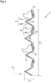
- Figures 1 and 2 are schematic side views of an example stent in a fully radially expanded state.
- the stent comprises an elongate frame 2.
- the frame 2 may be cylindrical for example.
- the maximum lateral dimension is the same at all positions and angles (i.e. it is equal to the diameter).
- the maximum lateral dimension may be different at different positions and/or angles.
- the maximum lateral dimension defines the minimum interior diameter of a cylindrical tube (e.g. a delivery catheter) that the frame could be inserted into.
- the frame 2 is configured such that the maximum lateral dimension of the frame can be reduced by elongating the frame longitudinally from the fully radially expanded state to a radially contracted state.
- This process is illustrated schematically in Figure 3 for the frame 2 of Figure 2 .
- Arrows 8 illustrate schematically the longitudinal extension and radially contraction.
- the frame 2 In the radially contracted state the frame 2 is substantially narrower than in the fully radially expanded state.
- the maximum lateral dimension is at least 30% smaller in the radially contracted state, preferably 50% smaller.
- Radially contracting the frame 2 allows the frame to be inserted into a narrower delivery catheter for deployment at the site of interest. It is generally desirable for the delivery catheter to be as narrow as possible. This is particularly the case where access to a deployment site requires navigation of tortuous regions of vasculature. This may often be the case, for example, when treating a cerebral aneurysm.
- the fully radially expanded state represents the configuration of the frame 2 at body temperature when no external force is applied to the frame 2.
- This state may therefore be referred to as the "relaxed" or “free” state.
- Reference is made to the temperature because the frame may be made of material, such as Nitinol, that is elastic at body temperature but plastic at other temperatures, for example at very low temperatures.
- the frame 2 In the plastic state, the frame 2 may be made to stay in a plastically deformed state of a different radius without any external force being applied to it. However, when the frame 2 returns to body temperature the frame 2 may become elastic again and return to the expected radius associated with the fully radially expanded state.
- porosity refers to the ratio of the surface area of open regions to the total external surface area occupied by the frame or portion of frame that is being described.
- the total external surface area is the sum of the surface area of the open regions and the surface area of the regions occupied by the material of the frame.
- the total external surface area is simply 2 ⁇ .R.L, where R is the radius of the cylinder and L is the length of the cylinder.
- the frame 2 comprises a low porosity region 4 for spanning the opening (also referred to as the "neck") to an aneurysmal sac.
- the low porosity region 4 has a porosity of less than 50% when the frame is in the fully radially expanded state.
- the frame 2 is preferably configured so that the maximum radius in the fully radially expanded state is close to, preferably slightly greater than, for example 10% greater than, the nominal radius of the blood vessel (e.g. the radius that the blood vessel would have in the the absence of the aneurysmal sac, or the radius of the blood vessel in the region of the blood vessel immediately outside of the opening to the aneurysmal sac).
- the low porosity region 4 Configuring the low porosity region 4 to have a porosity of less than 50% when the frame 2 is in the fully radially expanded state ensures that the porosity of the portion of the frame 2 that spans the opening to the sac when the stent is deployed is less than 50%.
- a porosity of less than 50% will inhibit the flow of blood into the aneurysmal sac to an extent that should promote blood clotting in most cases.
- the porosity of the low porosity region when the frame 2 is in the fully radially expanded state is less than 40%, more preferably less than 30%, more preferably less than 20%. Making the porosity lower increases the extent to which blood flow is diverted away from the sac and further encourages blood clotting within the sac.
- the low porosity region 4 is surrounded by a higher porosity region 6, both longitudinally and circumferentially.
- the frame 2 would have to be oriented correctly (both longitudinally and azimuthally) when deployed so that the low porosity region 4 is placed over the opening to the sac.
- Figure 2 illustrates an alternative configuration where the low porosity region 4 expands all the way around the circumference of the frame 2 and along all or a portion of the length of the frame 2.
- the arrangement of Figure 2 may be easier to deploy because it is no longer necessary to consider the azimuthal alignment of the stent.
- the position of the stent longitudinally does not need to be controlled as accurately because the low porosity region 4 expands further longitudinally.
- an expanded region of low porosity may act to divert blood flow away from openings other than the opening to the sac, for example openings to branch vessels, which is undesirable.
- the size and shape of the low porosity region 2 may be configured differently.
- the porosity may be configured to vary more gradually, rather than suddenly changing at the boundary of the low porosity region. Such gradual changes may reduce the likelihood of damage or irritation to tissue.
- the low porosity region 4 is bounded by higher porosity regions in both longitudinal directions, and circumferentially.
- the low porosity region may be bounded on only one longitudinal side by a higher porosity region. Additionally or alternatively, the low porosity region may expand all the way around the circumference in a closed loop.
- the frame is configured so that it can be elongated by at least 25%, more preferably by at least 50%, even more preferably by 100% or 150%.
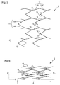
- Figure 4 is a schematic plan view of a portion of an example frame 2, in the fully radially expanded state, notionally unwrapped from its actual cylindrical or tubular shape into a flat shape, where L 0 is the longitudinal length and C 0 is the circumference.
- the frame 2 comprises a network of interconnecting arms 10.
- the interconnecting arms 10 form a plurality of longitudinally deformable elements 12 and a plurality of circumferentially deformable elements 14.
- each longitudinally deformable element 12 consists of two arms 12A and 12B that are connected together at an elbow 12C.
- the angle at the elbow 12C is labelled ⁇ 0 .
- each circumferentially deformable element 14 consists of two arms 14A and 14B connected together at an elbow 14C.
- the angle at the elbow 14C is labelled ⁇ 0 .
- a smaller ⁇ 0 can lead to lower porosity and higher longitudinal flexibility.
- Folding of the frame 2 can be divided into two steps: a longitudinal extension and a radial contraction.
- the steps can be carried out one after the other or at the same time. If the steps are carried out at the same time, the longitudinal extension must progress sufficiently quickly relative to the radial contraction that any circumferentially deformable elements that overlap in the longitudinal direction initially are displaced longitudinally by a sufficient distance that they do not come into contact prematurely in the circumferential direction and block the radial contraction.
- the state of the frame 2 after a longitudinal extension is illustrated schematically in Figure 5 .
- the extension along L is accommodated by an increase in the angle at the elbows 12C of the longitudinally deformable elements from ⁇ 0 to ⁇ 1 , where ⁇ 1 can in general be any value larger than ⁇ 0 .
- the state of the frame 2 after a subsequent radial contraction is illustrated schematically in Figure 6 .
- the radial contraction (corresponding to a reduction in the length of the unfolded frame 2 along the C direction) is accommodated by a reduction in the angle at the elbows 14C of the circumferentially deformable elements 14 from ⁇ 0 to ⁇ 1 , where ⁇ 1 can in general be any value smaller than ⁇ 0 , and L 1 and C 1 are the length and circumference of the radially contracted frame 2, respectively.
- the frame layout in Figure 6 represents an example of a frame in the radially contracted state, suitable for insertion into a delivery catheter for example.
- the frame 2 could be contracted further until the angle ⁇ 1 becomes as close to zero as is possible without causing buckling/damage to the elbows 14C.
- the longitudinally deformable elements 12 may be connected to the circumferentially deformable elements 14 in such a way that longitudinal extension of the longitudinally deformable elements 12 causes longitudinal displacement of the circumferentially deformable elements with which they are in contact (with or without deformation of the circumferentially deformable elements 14).
- This functionality can be seen to occur in the embodiment of Figures 4 to 6 .
- Neighbouring "V-shaped" circumferentially deformable elements 14 can be seen to be driven further apart by extension of the longitudinally deformable elements 12 (see transition from Figure 4 to Figure 5 ).
- a first one of the circumferentially deformable elements 14 has a portion that is bounded on one or both sides in the circumferential direction by a portion of a second circumferentially deformable element 14 when the frame 2 is in the fully radially expanded state, there is a risk that these two circumferentially deformable elements 14 could be driven into contact with each other circumferentially during radial contraction, thus blocking the radial contraction.
- the elongation should therefore progress so as to avoid this. This is achieved by coupling the circumferentially deformable elements 14 to the longitudinally deformable elements 12 in such a way that the circumferentially deformable elements 14 are driven apart during the elongation by a sufficient amount to remove any longitudinal overlap (i.e.
- the longitudinally deformable elements 12 can be expanded or contracted without any corresponding circumferential contraction or extension of the circumferentially deformable elements 14.
- the circumferentially deformable elements 14 may be displaced without any change in the shape of the circumferentially deformable elements (the extension of the frame being provided entirely by deformation of the longitudinally deformable elements).
- the circumferentially deformable elements may be configured to contract radially when the longitudinally deformable elements are extended and vice versa This is the case in the arrangement of Figures 9 and 10 for example.
- the circumferentially deformable elements may be configured so that they can contract or expand to a degree without any corresponding extension or contraction of the longitudinally deformable elements. This is the case in the embodiment of Figures 4 to 6 , for example, where the circumferential contraction is possible up until longitudinally neighbouring circumferentially deformable elements come into contact.
- the degree of movement could be increased by increasing the separation between the circumferentially deformable elements 14, but this would tend to increase the porosity of the frame 2 in the fully radially expanded state.
- longitudinal extension will involve a degree of circumferential contraction of the longitudinally deformable elements.
- circumferentially deformable elements are provided, as in the embodiments of Figures 4 to 8 , in switching from the fully radially expanded state to a radially contracted state suitable for inserting the stent into a delivery catheter, the majority of the circumferential contraction will generally be provided by the circumferentially deformable elements.
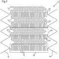
- Figures 4 to 6 can be repeated in the longitudinal direction L to form a longer frame 2.
- Figure 7 shows an example of a longer frame 2 consisting of 10 repeating basic forms of the type shown in Figures 4 to 6 (although the elbows have been made more rounded, which may be desirable to avoid stresses in the frame 2, and to avoid the presence of sharp elements that may cause irritation or damage to tissue).
- Figure 7 also shows an example of how to design the ends 16 of the frame 2. In this example, a zigzag ring 16 is connected to each end of the frame 2.
- each set comprising a plurality of elements 12 connected together so as to act in series.
- the broken-line box 18 contains elements 12 in one of the four sets.
- the elements 12 in each set are also aligned with each other in a direction parallel to the axis of the frame 2.
- the elements 12 in each set are connected directly to each other, but this need not be the case. In other embodiments, fewer than four sets may be provided, or more than four sets may be provided.
- each of the four sets of elements 12 is separated from each of the two circumferentially neighbouring sets by a set of the circumferentially deformable elements 14.
- Broken-line box 20 contains elements 14 in one of these sets.
- Four such sets of elements 14 are present in this embodiment, so as to provide a circumferentially alternating sequence of elements (alternating between the elements 12 and the elements 14).
- Four example fewer than four sets of elements 14 may be provided, or more than four sets of elements 14 may be provided. Different circumferential sequences may be provided.
- Figure 8 shows an example of a frame 2 having six sets of the longitudinally deformable elements 12 and six sets of the circumferentially deformable elements 14.
- reducing the number of sets of circumferentially deformable elements 14 will tend to increase longitudinal flexibility.
- having a larger number of sets of elements may limit the extent to which the frame 2 can be elongated and thus the extent to which the frame can be radially contracted for a given porosity in the fully radially expanded state.
- Figures 9 and 10 illustrate schemetically the geometry of an arrangement (not forming part of the invention) comprising a plurality of deformable elements 22 that provide both longitudinal and circumferential extension (and contraction).
- a plurality of such deformable elements 22 together provide all (or a majority of) the longitudinal extension/contraction and circumferential extension/contraction of the frame 2.
- Each deformable element 22 may be considered as made up of four elements 22A, 22B, 22C and 22D connected together at four elbows to form a closed shape, for example a diamond shape.
- Longitudinal extension and circumferential contraction of the element 22 are achieved by reducing the angle at the elbows 22E.
- Longitudinal contraction and circumferential extension of the element 22 are achieved by increasing the angle at the elbows 22F.
- the elements 22 are connected directly to each other both longitudinally and circumferentially.
- the elements 22 are configured to form a lattice having a constant spatial period both longitudinally and circumferentially.
- the elements 22 may be configured to form a lattice that has a constant periodicity in the circumferential direction but a varying periodicity in the longitudinal direction.
- the elements 22 may be configured to form a lattice that has a constant periodicity in the longitudinal direction but a varying periodicity in the circumferential direction.
- Such arrangements make it possible to vary the porosity of the frame 2 as a function of position, for example so as to make a central region have lower porosity than more peripheral regions.
- the deformable elements 22 may be referred to as longitudinally deformable elements that are capable of supporting circumferential extension, or as circumferentially deformable elements that are capable of supporting longitudinal extension.
- a longitudinal extension of the deformable element 22 will be accompanied by a circumferential contraction of the element 22 and vice versa.
- Figures 9 and 10 show a structure comprising six deformable elements 22 (as we have defined them): three longitudinal rows each comprises two elements 22. Other configurations are possible. For example, each element 22 may be constructed differently. More than two or fewer than two (e.g. one or half of one) element 22 may be provided in each row. More than three or fewer than three rows may be provided.
- the lattice structure shown in Figures 9 and 10 can be characterized by reference to an angle ⁇ 1 by analogy with the arrangements depicted in Figure 4 to 6 .
- the frame 2 of Figures 9 and 10 may be seen as a variation of the embodiment of Figures 4 to 6 in which the circumferentially deformable elements 14 are omitted, such that circumferentially neighbouring sets of longitudinally aligned longitudinally deformable elements 12 are connected to each other directly (rather than via the circumferentially deformable elements 14).
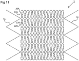
- Figure 11 shows an example of a frame 2 comprising seven units of the type illustrated in Figures 9 and 10 , connected to each other in a longitudinal direction.
- the arms 22A, 22B, 22C, 22D making up each deformable element 22 are rounded rather than straight to avoid sharp angles.
- a zigzag ring 16 is provided at each end of the frame 2.
- Figure 12 shows an example of a frame 2 comprising two deformable elements in the circumferential direction rather than three (as in the embodiment of Figure 11 ).
- the flow-diverter can have any number of deformable elements 22 in the circumferential direction.
- the greater the number of deformable elements 22 in the circumferential direction the lower the flexibility of the frame 2.
- increasing the number of elements will tend to reduce the extent to which the frame 2 can be lengthened and thus limit the degree to which the frame 2 can be radially contracted for a given porosity in the fully radially expanded state.
- the frame 2 is constructed so as to have a constant porosity both longitudinally and circumferentially. This may be achieved by arranging for all of the longitudinally deformable elements 12 to be identical and for all of the circumferentially deformable elements 14 to be identical, for example, at all positions of the frame 2. In embodiments where the frame 2 comprises just one type of element 22 that accommodates both the longitudinal and radial extension/contraction, all of the elements 22 may be provided in identical form at all positions on the frame 2. In these arrangements, the porosity of the frame 2 is thus constant as a function of position (at the resolution of individual deformable elements 12, 14, 22). However, this is not essential.
- the nature of the deformable elements 12, 14, 22 can be varied as a function of position to provide a porosity that varies as a function of position.
- the porosity may be made to vary as a function of position in the longitudinal direction, in the circumferential direction, or both.
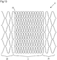
- Figure 13 depicts an example arrangement of the type shown in Figures 9 to 12 except the deformable elements 22 are configured to have a porosity that varies in the longitudinal direction.
- a central region which may correspond to the low porosity region 4 of the frame 2
- the deformable elements 22 are relatively closely spaced and have a low porosity.
- longitudinally peripheral regions 24 the deformable elements 22 are configured to be less closely spaced, thus providing a higher porosity.
- the deformable elements 22 could be arranged to have porosity that varies in the circumferential direction also.
- the arrangement of Figure 13 could be adapted so that the low porosity region 4 is surrounded on the top and bottom sides also by a higher porosity region.
- the ability to vary the porosity in this way provides useful design flexibility. For example, it allows the low porosity region 4 to be made smaller so as to target the neck of the aneurysmal sac more precisely. In this way it is possible to avoid unnecessarily positioning low porosity portions of the frame 2 against regions of tissue that are not associated with the aneurysm. Low porosity regions of the frame 2 will tend to be stiffer and more likely to cause irritation or damage to tissue. They may exert a larger radial force against tissue for example. The stiffness may also disadvantageously limit the extent to which the frame 2 can conform well with tortuous regions of vasculature, so it may be desirable to minimise the size of the low porosity region 4 for this reason also.
- the opening to the aneurysmal sac may be located in close proximity to one or more other openings (e.g. branch blood vessels) which should not be blocked.
- Controlling the size and shape of the low porosity region 4 in the way described makes it possible to tailor the frame 2 so that the low porosity region 4 of the stent is positioned over the opening the aneurysmal sac while neighbouring openings are covered only (or mainly) by higher porosity regions of the frame 2.
- the frame 2 may be manufactured from a sheet of material from which the structures described above are cut.
- the cutting may be performed, for example and without limitation, by laser cutting which can provide the desired accuracy in a straightforward manner.
- the cutting is performed to produce the frame 2 in its fully radially expanded (unconstrained) state.
- the frame 2 may be polished after the cutting to remove sharp edges, which may assist with inserting the frame into a delivery catheter for example and/or reduce the chances of irritation or injury to a patient.
- the sheet of material may initially be formed as a tube, for example by extrusion.
- the cutting is performed directly on the tube.
- the sheet of material may initially be formed as a flat sheet, which is subsequently curved into a tube and joined along the facing edges, for example by laser welding.
- the cutting may be performed on the flat sheet before joining or on the joined tube.
- the cutting may be performed, for example and without limitation, by chemical etching.
- the material of the sheet may in general be any biocompatible material, for example a metal, for example 316L stainless steel. Generally, a biocompatible material is selected with appropriate mechanical properties for the site at which the frame 2 is to be used.
- the sheet may be a unitary piece of material or a multi-layer material. The sheet may or may not be coated with a substance for adapting the physical properties of the frame 2 and/or with a medicament which the frame 2 thus delivers.
- a superelastic material for example a shape memory alloy, for example Nitinol.
- the use of a superelastic material has the advantage that the frame 2 may be self-expanding in situ.
- the material is selected so that it is in the superelastic state at the temperature in situ (body temperature).
- the frame 2 may consists of a network of interconnecting arms.
- the interconnecting arms may be formed by cutting out the material in between the arms, using a laser for example.
- the network of interconnected arms may be cut from a cylindrical tube for example. All of the interconnected arms may lie at a common radius, so as to form a cylinder.
- the frame 2 cross-section may appear circular. This configuration may persist for all configurations of the frame 2 that are expected in normal use, from the fully expanded state to the maximally radially contracted state.
- the maximally radially contracted state may be defined as the state in which any further radial contraction of the frame 2 would involve buckling of the frame (i.e.
- the maximally radially contracted state will correspond to a state which has very low or zero porosity, where all or a very large proportion of the interconnected arms are very close to or in contact with neighbouring arms at points other than the points of connection between the arms, for example along their length.
- the frame 2 may be inserted into the region to be treated using a delivery catheter.
- the delivery catheter may comprise a narrow tube, for example.
- the inner diameter of the part of the delivery catheter that will receive the frame 2 may be less than 5mm, or less than 3mm, so that the radius of the frame in the radially contracted state will need to be less then 2.5mm or less than 1.5mm respectively. It is desirable to make the delivery catheter as narrow as possible to facilitate the insertion process and minimize the risk of irritation or injury to the patient. Thinner delivery catheters may be able to access regions that thicker delivery catheters cannot.
- Insertion of a frame into the delivery catheter could be difficult to achieve efficiently and reproducibly due to the small dimension involved. Described below are two example approaches for inserting the frame which address this challenge.
- the frame is formed from a material that undergoes a temperature induced phase transition from a state in which it can be deformed plastically and a state in which it is elastic.
- a material that undergoes a temperature induced phase transition from a state in which it can be deformed plastically and a state in which it is elastic.
- Nitinol which adopts a highly elastic austenite phase at body temperature and a weaker, plastically deformable martensite phase at lower temperatures.
- a frame formed from such a material can be cooled to a temperature at which the deformation is predominantly plastic, elongated and radially contracted to form the radially contracted state while still cold, and then inserted into the delivery catheter.
- the cooling can be carried out by immersing the frame in a bath of liquid alcohol for example.
- the frame is warmed back up to room temperature or body temperature it will become elastic again but is restrained by the interior walls of the delivery catheter until the frame is to be deployed.
- the frame is to be deployed, it is pushed out of the delivery catheter.
- an arrangement which allows the frame to be inserted into the delivery catheter in a single pushing action.
- the use of a single pushing action makes it possible to insert the frame into the delivery catheter efficiently and reliably without first having to cool the frame down to a plastic state.
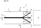
- FIG. 14 An example configuration is depicted schematically in Figure 14 .
- the left part of the figure depicts a leading end of a frame 2 and the right part of the figure depicts a facing end of a delivery catheter 32 into which the frame 2 is to be inserted.
- the direction of insertion is shown by arrows 36.
- the low porosity region 4 is not shown in detail.
- the leading edge of the frame 2 is adapted so as to present one or more anchoring points 30.
- the leading edge of the frame 2 may be provided with a zigzag structure 16 having elbows pointing longitudinally forwards.
- the anchoring points 30 allow for engagement with a longitudinally rigid element 26. In the example shown, the engagement between the anchoring points 30 and the element 26 are provided by means of laterally spreading arms 28.
- laterally spreading arms 28 comprise hooks or similar that allow engagement with the elbows of the zigzag elements 16.
- the engagement between the element 26 and the frame 2 might be realized in different ways. In general, any engagement that is capable of transmitting a longitudinal force applied to the element 26 (see arrow 34) to the leading edge of the frame 2 may be used.
- the insertion process may proceed as follows. An end of the frame 2 opposite to the leading end of the frame 2 (depicted) is secured longitudinally. The longitudinally rigid element 26 is then inserted into the frame 2 from the end of the frame 2 opposite to the leading end of the frame and pushed through until the element engages with the leading end of the frame 2 (for example by means of anchoring points 30). The rigid element 26 is then forced further forwards. The force is transmitted to the frame 2 and the frame is made to elongate. Depending on the particular structure of the frame 2, the force of elongation may cause a simultaneous radially contraction, such that the frame 2 eventually adopts a radially contracted state that is sufficiently narrow to fit into the delivery catheter without any separate force needed radially. If a separate radially inwards force is needed to provide the radial contraction, this can be provided separately (e.g. by manual compression) or a structure such as a funnel positioned in the delivery catheter 32 can be used to assist.
- Insertion of the stent into the delivery catheter may be further facilitated by lubricating the frame 2 and/or by polishing the frame 2 to make the outer surface of the frame 2 smoother.
- a stent comprising a frame
- this is to include a stent that consists of the frame (i.e. with no other elements) and a stent that consists of the frame and other additional elements.
Landscapes
- Health & Medical Sciences (AREA)
- Engineering & Computer Science (AREA)
- Biomedical Technology (AREA)
- Life Sciences & Earth Sciences (AREA)
- Veterinary Medicine (AREA)
- Heart & Thoracic Surgery (AREA)
- Vascular Medicine (AREA)
- Animal Behavior & Ethology (AREA)
- General Health & Medical Sciences (AREA)
- Public Health (AREA)
- Transplantation (AREA)
- Oral & Maxillofacial Surgery (AREA)
- Cardiology (AREA)
- Surgery (AREA)
- Physics & Mathematics (AREA)
- Optics & Photonics (AREA)
- Nuclear Medicine, Radiotherapy & Molecular Imaging (AREA)
- Reproductive Health (AREA)
- Medical Informatics (AREA)
- Molecular Biology (AREA)
- Neurosurgery (AREA)
- Gastroenterology & Hepatology (AREA)
- Pulmonology (AREA)
- Prostheses (AREA)
- Media Introduction/Drainage Providing Device (AREA)
- Materials For Medical Uses (AREA)
- Surgical Instruments (AREA)
Priority Applications (1)
| Application Number | Priority Date | Filing Date | Title |
|---|---|---|---|
| PL12762027T PL2753271T3 (pl) | 2011-09-09 | 2012-09-07 | Stent i sposób wprowadzania stentu do cewnika wprowadzającego |
Applications Claiming Priority (2)
| Application Number | Priority Date | Filing Date | Title |
|---|---|---|---|
| GB1115671.8A GB2494632A (en) | 2011-09-09 | 2011-09-09 | Stent and method of inserting a stent into a delivery catheter |
| PCT/GB2012/052215 WO2013034930A2 (en) | 2011-09-09 | 2012-09-07 | Stent and method of inserting a stent into a delivery catheter |
Publications (2)
| Publication Number | Publication Date |
|---|---|
| EP2753271A2 EP2753271A2 (en) | 2014-07-16 |
| EP2753271B1 true EP2753271B1 (en) | 2018-01-17 |
Family
ID=44908371
Family Applications (1)
| Application Number | Title | Priority Date | Filing Date |
|---|---|---|---|
| EP12762027.6A Active EP2753271B1 (en) | 2011-09-09 | 2012-09-07 | Stent and method of inserting a stent into a delivery catheter |
Country Status (12)
| Country | Link |
|---|---|
| US (2) | US9301861B2 (ja) |
| EP (1) | EP2753271B1 (ja) |
| JP (1) | JP6159330B2 (ja) |
| CN (2) | CN104039275B (ja) |
| DK (1) | DK2753271T3 (ja) |
| ES (1) | ES2664839T3 (ja) |
| GB (1) | GB2494632A (ja) |
| HU (1) | HUE038520T2 (ja) |
| NO (1) | NO2753271T3 (ja) |
| PL (1) | PL2753271T3 (ja) |
| TR (1) | TR201802661T4 (ja) |
| WO (1) | WO2013034930A2 (ja) |
Families Citing this family (8)
| Publication number | Priority date | Publication date | Assignee | Title |
|---|---|---|---|---|
| US11484322B2 (en) | 2018-01-03 | 2022-11-01 | Aneuclose Llc | Aneurysm neck bridge with a closeable opening or lumen through which embolic material is inserted into the aneurysm sac |
| US11464518B2 (en) | 2008-05-01 | 2022-10-11 | Aneuclose Llc | Proximal concave neck bridge with central lumen and distal net for occluding cerebral aneurysms |
| US11471163B2 (en) | 2008-05-01 | 2022-10-18 | Aneuclose Llc | Intrasaccular aneurysm occlusion device with net or mesh expanded by string-of-pearls embolies |
| GB2494632A (en) | 2011-09-09 | 2013-03-20 | Isis Innovation | Stent and method of inserting a stent into a delivery catheter |
| GB201704720D0 (en) | 2017-03-24 | 2017-05-10 | Oxford Endovascular Ltd | A expandable tube for deployment within a blood vessel |
| EP3793660A2 (en) | 2018-05-17 | 2021-03-24 | Route 92 Medical, Inc. | Aspiration catheter systems and methods of use |
| US20210353300A1 (en) * | 2020-05-15 | 2021-11-18 | DePuy Synthes Products, Inc. | Systems and methods for treatment of defects in the vasculature |
| US20230355413A1 (en) * | 2022-05-04 | 2023-11-09 | Route 92 Medical, Inc. | Systems and methods for treating vascular disease |
Family Cites Families (44)
| Publication number | Priority date | Publication date | Assignee | Title |
|---|---|---|---|---|
| EP0657147B1 (en) * | 1993-11-04 | 1999-08-04 | C.R. Bard, Inc. | Non-migrating vascular prosthesis |
| DK171865B1 (da) * | 1995-09-11 | 1997-07-21 | Cook William Europ | Ekspanderbar endovasculær stent |
| CA2214627A1 (en) * | 1997-03-05 | 1998-09-05 | Divysio Solutions Ulc | Expandable stent |
| US6451049B2 (en) * | 1998-04-29 | 2002-09-17 | Sorin Biomedica Cardio, S.P.A. | Stents for angioplasty |
| CA2424551A1 (en) * | 1997-05-27 | 1998-11-27 | Schneider (Usa) Inc. | Stent and stent-graft for treating branched vessels |
| US5951599A (en) * | 1997-07-09 | 1999-09-14 | Scimed Life Systems, Inc. | Occlusion system for endovascular treatment of an aneurysm |
| CA2320868C (en) * | 1998-02-12 | 2008-08-12 | Thomas R. Marotta | Endovascular prosthesis |
| CN2322571Y (zh) * | 1998-04-17 | 1999-06-09 | 陈洁 | 具有轴向长度补偿的血管内支架 |
| US6261319B1 (en) * | 1998-07-08 | 2001-07-17 | Scimed Life Systems, Inc. | Stent |
| JP2000037462A (ja) * | 1998-07-24 | 2000-02-08 | Tokin Corp | ステント |
| US6616689B1 (en) * | 2000-05-03 | 2003-09-09 | Advanced Cardiovascular Systems, Inc. | Intravascular stent |
| US6814754B2 (en) * | 2000-10-30 | 2004-11-09 | Secant Medical, Llc | Woven tubular graft with regions of varying flexibility |
| CN2453962Y (zh) * | 2000-12-08 | 2001-10-17 | 杨大智 | 一种镂制正弦波管网式冠状动脉支架 |
| US6540773B2 (en) * | 2001-07-03 | 2003-04-01 | Scimed Life Systems, Inc. | Low profile, high stretch knit prosthetic device |
| CA2452953A1 (en) * | 2001-07-18 | 2003-01-30 | The Research Foundation Of State University Of New York | Stent vascular intervention device and method |
| US7169177B2 (en) * | 2003-01-15 | 2007-01-30 | Boston Scientific Scimed, Inc. | Bifurcated stent |
| JP2005192933A (ja) * | 2004-01-09 | 2005-07-21 | Goodman Co Ltd | 補綴搬送システム、補綴搬送システム組立方法、および補綴搬送システム用キット |
| AU2010236494B2 (en) * | 2004-05-25 | 2013-05-30 | Covidien Lp | Vascular stenting for aneurysms |
| US8623067B2 (en) * | 2004-05-25 | 2014-01-07 | Covidien Lp | Methods and apparatus for luminal stenting |
| US20050283220A1 (en) * | 2004-06-22 | 2005-12-22 | Gobran Riad H | Blood flow diverters for the treatment of intracranial aneurysms |
| US7318835B2 (en) * | 2004-07-20 | 2008-01-15 | Medtronic Vascular, Inc. | Endoluminal prosthesis having expandable graft sections |
| US7361189B2 (en) * | 2004-09-10 | 2008-04-22 | Cook Incorporated | Prosthetic valve with pores |
| CA2915597C (en) * | 2004-09-17 | 2018-01-23 | Cordis Neurovascular, Inc. | Thin film devices for occlusion of a vessel |
| US20060155367A1 (en) * | 2005-01-07 | 2006-07-13 | Hines Richard A | Micro-pleated stent assembly |
| WO2006126182A2 (en) * | 2005-05-24 | 2006-11-30 | Inspire M.D Ltd. | Stent apparatuses for treatment via body lumens and methods of use |
| WO2007002933A2 (en) * | 2005-06-28 | 2007-01-04 | Stout Medical Group, Inc. | Micro-thin film structures for cardiovascular indications |
| WO2007013977A2 (en) * | 2005-07-21 | 2007-02-01 | The Research Foundation Of State University Of New York | Stent vascular intervention device and methods for treating aneurysms |
| US8956400B2 (en) * | 2005-10-14 | 2015-02-17 | Flexible Stenting Solutions, Inc. | Helical stent |
| JP2007117548A (ja) * | 2005-10-31 | 2007-05-17 | Japan Stent Technology Co Ltd | ステント |
| CN101415380B (zh) | 2006-04-07 | 2012-06-20 | 半影公司 | 动脉瘤阻塞装置 |
| US8814930B2 (en) * | 2007-01-19 | 2014-08-26 | Elixir Medical Corporation | Biodegradable endoprosthesis and methods for their fabrication |
| US20110022149A1 (en) * | 2007-06-04 | 2011-01-27 | Cox Brian J | Methods and devices for treatment of vascular defects |
| DE102007061931A1 (de) * | 2007-12-21 | 2009-06-25 | Acandis Gmbh & Co. Kg | Medizinisches Implantat |
| US7806919B2 (en) * | 2008-04-01 | 2010-10-05 | Medtronic Vascular, Inc. | Double-walled stent system |
| MX2011000857A (es) * | 2008-07-22 | 2011-07-28 | Tyco Healthcare | Dispositivo de remodelacion vascular. |
| WO2011025887A1 (en) * | 2009-08-27 | 2011-03-03 | Boston Scientific Scimed, Inc. | Stent with variable cross section braiding filament and method for making same |
| US9358140B1 (en) * | 2009-11-18 | 2016-06-07 | Aneuclose Llc | Stent with outer member to embolize an aneurysm |
| WO2012158881A1 (en) * | 2011-05-19 | 2012-11-22 | Tyco Healthcare Group Lp | Vascular remodeling device |
| GB2494632A (en) | 2011-09-09 | 2013-03-20 | Isis Innovation | Stent and method of inserting a stent into a delivery catheter |
| US20130123901A1 (en) * | 2011-11-14 | 2013-05-16 | Robert A. Connor | Stent with in situ determination of wall areas with differences in porosity |
| US9452070B2 (en) * | 2012-10-31 | 2016-09-27 | Covidien Lp | Methods and systems for increasing a density of a region of a vascular device |
| US9498360B2 (en) * | 2013-03-15 | 2016-11-22 | Stryker Corporation | Stent and method of use |
| US20150032202A1 (en) * | 2013-07-26 | 2015-01-29 | New York University | Drug-Eluting Stent and Method |
| JP6549717B2 (ja) * | 2015-01-12 | 2019-07-24 | マイクロベンション インコーポレイテッドMicrovention, Inc. | ステント |
-
2011
- 2011-09-09 GB GB1115671.8A patent/GB2494632A/en not_active Withdrawn
-
2012
- 2012-09-07 ES ES12762027.6T patent/ES2664839T3/es active Active
- 2012-09-07 NO NO12762027A patent/NO2753271T3/no unknown
- 2012-09-07 US US14/343,522 patent/US9301861B2/en active Active
- 2012-09-07 EP EP12762027.6A patent/EP2753271B1/en active Active
- 2012-09-07 WO PCT/GB2012/052215 patent/WO2013034930A2/en active Application Filing
- 2012-09-07 PL PL12762027T patent/PL2753271T3/pl unknown
- 2012-09-07 TR TR2018/02661T patent/TR201802661T4/tr unknown
- 2012-09-07 CN CN201280055173.2A patent/CN104039275B/zh active Active
- 2012-09-07 DK DK12762027.6T patent/DK2753271T3/en active
- 2012-09-07 CN CN201610644809.7A patent/CN106264643B/zh active Active
- 2012-09-07 JP JP2014529070A patent/JP6159330B2/ja active Active
- 2012-09-07 HU HUE12762027A patent/HUE038520T2/hu unknown
-
2016
- 2016-04-05 US US15/091,540 patent/US10383749B2/en active Active
Also Published As
| Publication number | Publication date |
|---|---|
| GB201115671D0 (en) | 2011-10-26 |
| GB2494632A (en) | 2013-03-20 |
| CN104039275A (zh) | 2014-09-10 |
| PL2753271T3 (pl) | 2018-07-31 |
| JP6159330B2 (ja) | 2017-07-05 |
| CN106264643B (zh) | 2019-08-06 |
| NO2753271T3 (ja) | 2018-06-16 |
| US9301861B2 (en) | 2016-04-05 |
| CN104039275B (zh) | 2016-09-14 |
| JP2014526294A (ja) | 2014-10-06 |
| TR201802661T4 (tr) | 2018-03-21 |
| EP2753271A2 (en) | 2014-07-16 |
| US20150190256A1 (en) | 2015-07-09 |
| US20160220396A1 (en) | 2016-08-04 |
| DK2753271T3 (en) | 2018-03-12 |
| WO2013034930A2 (en) | 2013-03-14 |
| ES2664839T3 (es) | 2018-04-23 |
| WO2013034930A3 (en) | 2013-07-25 |
| CN106264643A (zh) | 2017-01-04 |
| US10383749B2 (en) | 2019-08-20 |
| HUE038520T2 (hu) | 2018-10-29 |
Similar Documents
| Publication | Publication Date | Title |
|---|---|---|
| EP2753271B1 (en) | Stent and method of inserting a stent into a delivery catheter | |
| EP2854704B1 (en) | Aneurysm occlusion system | |
| US20190133794A1 (en) | Methods and systems for increasing a density of a region of a vascular device | |
| EP2800529B1 (en) | Braided devices for assisting medical treatments | |
| AU2007268135B2 (en) | Flexible vascular occluding device | |
| US20070239261A1 (en) | Aneurysm occlusion system and method | |
| JP2014054557A (ja) | フレキシブルな血管閉鎖デバイス | |
| US11583423B2 (en) | Expandable tube for deployment within a blood vessel | |
| EP3600173B1 (en) | Delivery system for deploying a self-expanding tube | |
| WO2010082026A1 (en) | Stent | |
| WO2024009055A1 (en) | An expandable tube for deployment within a blood vessel |
Legal Events
| Date | Code | Title | Description |
|---|---|---|---|
| PUAI | Public reference made under article 153(3) epc to a published international application that has entered the european phase |
Free format text: ORIGINAL CODE: 0009012 |
|
| 17P | Request for examination filed |
Effective date: 20140404 |
|
| AK | Designated contracting states |
Kind code of ref document: A2 Designated state(s): AL AT BE BG CH CY CZ DE DK EE ES FI FR GB GR HR HU IE IS IT LI LT LU LV MC MK MT NL NO PL PT RO RS SE SI SK SM TR |
|
| DAX | Request for extension of the european patent (deleted) | ||
| 17Q | First examination report despatched |
Effective date: 20160707 |
|
| RAP1 | Party data changed (applicant data changed or rights of an application transferred) |
Owner name: OXFORD UNIVERSITY INNOVATION LIMITED |
|
| STAA | Information on the status of an ep patent application or granted ep patent |
Free format text: STATUS: EXAMINATION IS IN PROGRESS |
|
| RAP1 | Party data changed (applicant data changed or rights of an application transferred) |
Owner name: OXFORD UNIVERSITY INNOVATION LIMITED |
|
| REG | Reference to a national code |
Ref country code: DE Ref legal event code: R079 Ref document number: 602012042139 Country of ref document: DE Free format text: PREVIOUS MAIN CLASS: A61F0002910000 Ipc: A61F0002915000 |
|
| RIC1 | Information provided on ipc code assigned before grant |
Ipc: A61F 2/915 20130101AFI20170623BHEP |
|
| GRAP | Despatch of communication of intention to grant a patent |
Free format text: ORIGINAL CODE: EPIDOSNIGR1 |
|
| STAA | Information on the status of an ep patent application or granted ep patent |
Free format text: STATUS: GRANT OF PATENT IS INTENDED |
|
| INTG | Intention to grant announced |
Effective date: 20170907 |
|
| GRAS | Grant fee paid |
Free format text: ORIGINAL CODE: EPIDOSNIGR3 |
|
| GRAA | (expected) grant |
Free format text: ORIGINAL CODE: 0009210 |
|
| STAA | Information on the status of an ep patent application or granted ep patent |
Free format text: STATUS: THE PATENT HAS BEEN GRANTED |
|
| AK | Designated contracting states |
Kind code of ref document: B1 Designated state(s): AL AT BE BG CH CY CZ DE DK EE ES FI FR GB GR HR HU IE IS IT LI LT LU LV MC MK MT NL NO PL PT RO RS SE SI SK SM TR |
|
| REG | Reference to a national code |
Ref country code: GB Ref legal event code: FG4D |
|
| REG | Reference to a national code |
Ref country code: CH Ref legal event code: EP |
|
| REG | Reference to a national code |
Ref country code: IE Ref legal event code: FG4D |
|
| REG | Reference to a national code |
Ref country code: AT Ref legal event code: REF Ref document number: 963893 Country of ref document: AT Kind code of ref document: T Effective date: 20180215 |
|
| REG | Reference to a national code |
Ref country code: DE Ref legal event code: R096 Ref document number: 602012042139 Country of ref document: DE |
|
| REG | Reference to a national code |
Ref country code: DK Ref legal event code: T3 Effective date: 20180305 |
|
| REG | Reference to a national code |
Ref country code: CH Ref legal event code: NV Representative=s name: VENI GMBH, CH |
|
| REG | Reference to a national code |
Ref country code: SE Ref legal event code: TRGR |
|
| REG | Reference to a national code |
Ref country code: NL Ref legal event code: FP |
|
| REG | Reference to a national code |
Ref country code: ES Ref legal event code: FG2A Ref document number: 2664839 Country of ref document: ES Kind code of ref document: T3 Effective date: 20180423 |
|
| REG | Reference to a national code |
Ref country code: LT Ref legal event code: MG4D |
|
| REG | Reference to a national code |
Ref country code: NO Ref legal event code: T2 Effective date: 20180117 |
|
| PG25 | Lapsed in a contracting state [announced via postgrant information from national office to epo] |
Ref country code: HR Free format text: LAPSE BECAUSE OF FAILURE TO SUBMIT A TRANSLATION OF THE DESCRIPTION OR TO PAY THE FEE WITHIN THE PRESCRIBED TIME-LIMIT Effective date: 20180117 Ref country code: LT Free format text: LAPSE BECAUSE OF FAILURE TO SUBMIT A TRANSLATION OF THE DESCRIPTION OR TO PAY THE FEE WITHIN THE PRESCRIBED TIME-LIMIT Effective date: 20180117 Ref country code: CY Free format text: LAPSE BECAUSE OF FAILURE TO SUBMIT A TRANSLATION OF THE DESCRIPTION OR TO PAY THE FEE WITHIN THE PRESCRIBED TIME-LIMIT Effective date: 20180117 |
|
| PG25 | Lapsed in a contracting state [announced via postgrant information from national office to epo] |
Ref country code: LV Free format text: LAPSE BECAUSE OF FAILURE TO SUBMIT A TRANSLATION OF THE DESCRIPTION OR TO PAY THE FEE WITHIN THE PRESCRIBED TIME-LIMIT Effective date: 20180117 Ref country code: RS Free format text: LAPSE BECAUSE OF FAILURE TO SUBMIT A TRANSLATION OF THE DESCRIPTION OR TO PAY THE FEE WITHIN THE PRESCRIBED TIME-LIMIT Effective date: 20180117 Ref country code: IS Free format text: LAPSE BECAUSE OF FAILURE TO SUBMIT A TRANSLATION OF THE DESCRIPTION OR TO PAY THE FEE WITHIN THE PRESCRIBED TIME-LIMIT Effective date: 20180517 Ref country code: BG Free format text: LAPSE BECAUSE OF FAILURE TO SUBMIT A TRANSLATION OF THE DESCRIPTION OR TO PAY THE FEE WITHIN THE PRESCRIBED TIME-LIMIT Effective date: 20180417 |
|
| REG | Reference to a national code |
Ref country code: GR Ref legal event code: EP Ref document number: 20180401033 Country of ref document: GR Effective date: 20180829 |
|
| REG | Reference to a national code |
Ref country code: FR Ref legal event code: PLFP Year of fee payment: 7 |
|
| REG | Reference to a national code |
Ref country code: DE Ref legal event code: R097 Ref document number: 602012042139 Country of ref document: DE |
|
| REG | Reference to a national code |
Ref country code: HU Ref legal event code: AG4A Ref document number: E038520 Country of ref document: HU |
|
| PG25 | Lapsed in a contracting state [announced via postgrant information from national office to epo] |
Ref country code: AL Free format text: LAPSE BECAUSE OF FAILURE TO SUBMIT A TRANSLATION OF THE DESCRIPTION OR TO PAY THE FEE WITHIN THE PRESCRIBED TIME-LIMIT Effective date: 20180117 Ref country code: RO Free format text: LAPSE BECAUSE OF FAILURE TO SUBMIT A TRANSLATION OF THE DESCRIPTION OR TO PAY THE FEE WITHIN THE PRESCRIBED TIME-LIMIT Effective date: 20180117 Ref country code: EE Free format text: LAPSE BECAUSE OF FAILURE TO SUBMIT A TRANSLATION OF THE DESCRIPTION OR TO PAY THE FEE WITHIN THE PRESCRIBED TIME-LIMIT Effective date: 20180117 |
|
| PLBE | No opposition filed within time limit |
Free format text: ORIGINAL CODE: 0009261 |
|
| STAA | Information on the status of an ep patent application or granted ep patent |
Free format text: STATUS: NO OPPOSITION FILED WITHIN TIME LIMIT |
|
| PG25 | Lapsed in a contracting state [announced via postgrant information from national office to epo] |
Ref country code: SM Free format text: LAPSE BECAUSE OF FAILURE TO SUBMIT A TRANSLATION OF THE DESCRIPTION OR TO PAY THE FEE WITHIN THE PRESCRIBED TIME-LIMIT Effective date: 20180117 Ref country code: SK Free format text: LAPSE BECAUSE OF FAILURE TO SUBMIT A TRANSLATION OF THE DESCRIPTION OR TO PAY THE FEE WITHIN THE PRESCRIBED TIME-LIMIT Effective date: 20180117 |
|
| 26N | No opposition filed |
Effective date: 20181018 |
|
| PG25 | Lapsed in a contracting state [announced via postgrant information from national office to epo] |
Ref country code: SI Free format text: LAPSE BECAUSE OF FAILURE TO SUBMIT A TRANSLATION OF THE DESCRIPTION OR TO PAY THE FEE WITHIN THE PRESCRIBED TIME-LIMIT Effective date: 20180117 |
|
| PG25 | Lapsed in a contracting state [announced via postgrant information from national office to epo] |
Ref country code: MC Free format text: LAPSE BECAUSE OF FAILURE TO SUBMIT A TRANSLATION OF THE DESCRIPTION OR TO PAY THE FEE WITHIN THE PRESCRIBED TIME-LIMIT Effective date: 20180117 |
|
| PG25 | Lapsed in a contracting state [announced via postgrant information from national office to epo] |
Ref country code: LU Free format text: LAPSE BECAUSE OF NON-PAYMENT OF DUE FEES Effective date: 20180907 |
|
| PG25 | Lapsed in a contracting state [announced via postgrant information from national office to epo] |
Ref country code: MT Free format text: LAPSE BECAUSE OF NON-PAYMENT OF DUE FEES Effective date: 20180907 |
|
| PG25 | Lapsed in a contracting state [announced via postgrant information from national office to epo] |
Ref country code: PT Free format text: LAPSE BECAUSE OF FAILURE TO SUBMIT A TRANSLATION OF THE DESCRIPTION OR TO PAY THE FEE WITHIN THE PRESCRIBED TIME-LIMIT Effective date: 20180117 |
|
| PG25 | Lapsed in a contracting state [announced via postgrant information from national office to epo] |
Ref country code: MK Free format text: LAPSE BECAUSE OF NON-PAYMENT OF DUE FEES Effective date: 20180117 |
|
| REG | Reference to a national code |
Ref country code: AT Ref legal event code: UEP Ref document number: 963893 Country of ref document: AT Kind code of ref document: T Effective date: 20180117 |
|
| PGFP | Annual fee paid to national office [announced via postgrant information from national office to epo] |
Ref country code: TR Payment date: 20220905 Year of fee payment: 11 Ref country code: SE Payment date: 20220922 Year of fee payment: 11 Ref country code: NO Payment date: 20220921 Year of fee payment: 11 Ref country code: NL Payment date: 20220922 Year of fee payment: 11 Ref country code: IE Payment date: 20220919 Year of fee payment: 11 Ref country code: FI Payment date: 20220919 Year of fee payment: 11 Ref country code: DK Payment date: 20220926 Year of fee payment: 11 Ref country code: CZ Payment date: 20220829 Year of fee payment: 11 Ref country code: AT Payment date: 20220919 Year of fee payment: 11 |
|
| PGFP | Annual fee paid to national office [announced via postgrant information from national office to epo] |
Ref country code: PL Payment date: 20220830 Year of fee payment: 11 Ref country code: HU Payment date: 20220827 Year of fee payment: 11 Ref country code: GR Payment date: 20220920 Year of fee payment: 11 Ref country code: BE Payment date: 20220921 Year of fee payment: 11 |
|
| PGFP | Annual fee paid to national office [announced via postgrant information from national office to epo] |
Ref country code: CH Payment date: 20220928 Year of fee payment: 11 |
|
| PGFP | Annual fee paid to national office [announced via postgrant information from national office to epo] |
Ref country code: GB Payment date: 20230927 Year of fee payment: 12 |
|
| PGFP | Annual fee paid to national office [announced via postgrant information from national office to epo] |
Ref country code: FR Payment date: 20230920 Year of fee payment: 12 Ref country code: DE Payment date: 20230919 Year of fee payment: 12 |
|
| PGFP | Annual fee paid to national office [announced via postgrant information from national office to epo] |
Ref country code: ES Payment date: 20231019 Year of fee payment: 12 |
|
| PGFP | Annual fee paid to national office [announced via postgrant information from national office to epo] |
Ref country code: IT Payment date: 20230922 Year of fee payment: 12 |
|
| REG | Reference to a national code |
Ref country code: DK Ref legal event code: EBP Effective date: 20230930 |
|
| PG25 | Lapsed in a contracting state [announced via postgrant information from national office to epo] |
Ref country code: FI Free format text: LAPSE BECAUSE OF NON-PAYMENT OF DUE FEES Effective date: 20230907 Ref country code: CZ Free format text: LAPSE BECAUSE OF NON-PAYMENT OF DUE FEES Effective date: 20230907 |
|
| REG | Reference to a national code |
Ref country code: CH Ref legal event code: PL Ref country code: SE Ref legal event code: EUG |
|
| REG | Reference to a national code |
Ref country code: NL Ref legal event code: MM Effective date: 20231001 |
|
| REG | Reference to a national code |
Ref country code: AT Ref legal event code: MM01 Ref document number: 963893 Country of ref document: AT Kind code of ref document: T Effective date: 20230907 |