EP2752086B2 - Détection d'état de traitement d'objet à l'aide de rayonnement rf - Google Patents
Détection d'état de traitement d'objet à l'aide de rayonnement rf Download PDFInfo
- Publication number
- EP2752086B2 EP2752086B2 EP12773420.0A EP12773420A EP2752086B2 EP 2752086 B2 EP2752086 B2 EP 2752086B2 EP 12773420 A EP12773420 A EP 12773420A EP 2752086 B2 EP2752086 B2 EP 2752086B2
- Authority
- EP
- European Patent Office
- Prior art keywords
- energy
- feedback
- processing
- controller
- energy application
- Prior art date
- Legal status (The legal status is an assumption and is not a legal conclusion. Google has not performed a legal analysis and makes no representation as to the accuracy of the status listed.)
- Active
Links
- 238000012545 processing Methods 0.000 title claims description 266
- 230000005855 radiation Effects 0.000 title description 8
- 238000000034 method Methods 0.000 claims description 116
- 238000010411 cooking Methods 0.000 claims description 64
- 230000008569 process Effects 0.000 claims description 54
- 238000010438 heat treatment Methods 0.000 claims description 46
- 230000002596 correlated effect Effects 0.000 claims description 26
- 235000013305 food Nutrition 0.000 claims description 25
- 239000000126 substance Substances 0.000 claims description 17
- 230000001276 controlling effect Effects 0.000 claims description 13
- 230000004044 response Effects 0.000 claims description 13
- 238000012544 monitoring process Methods 0.000 claims description 10
- 238000010521 absorption reaction Methods 0.000 claims description 4
- 230000000704 physical effect Effects 0.000 claims description 4
- 230000005284 excitation Effects 0.000 description 149
- 235000013550 pizza Nutrition 0.000 description 29
- 230000008859 change Effects 0.000 description 18
- 230000006870 function Effects 0.000 description 18
- 239000000463 material Substances 0.000 description 16
- 238000010257 thawing Methods 0.000 description 15
- 238000002474 experimental method Methods 0.000 description 14
- 238000010408 sweeping Methods 0.000 description 10
- 238000005192 partition Methods 0.000 description 9
- 239000007788 liquid Substances 0.000 description 8
- 239000000203 mixture Substances 0.000 description 8
- 238000013515 script Methods 0.000 description 8
- 239000007787 solid Substances 0.000 description 6
- 238000012360 testing method Methods 0.000 description 6
- 240000004808 Saccharomyces cerevisiae Species 0.000 description 5
- 238000001035 drying Methods 0.000 description 5
- 235000013372 meat Nutrition 0.000 description 5
- 229920000642 polymer Polymers 0.000 description 5
- 238000006243 chemical reaction Methods 0.000 description 4
- 238000004891 communication Methods 0.000 description 4
- 239000000470 constituent Substances 0.000 description 4
- 230000003247 decreasing effect Effects 0.000 description 4
- 239000007789 gas Substances 0.000 description 4
- 230000007246 mechanism Effects 0.000 description 4
- 235000009499 Vanilla fragrans Nutrition 0.000 description 3
- 244000263375 Vanilla tahitensis Species 0.000 description 3
- 235000012036 Vanilla tahitensis Nutrition 0.000 description 3
- 229910045601 alloy Inorganic materials 0.000 description 3
- 239000000956 alloy Substances 0.000 description 3
- 230000005540 biological transmission Effects 0.000 description 3
- 230000000875 corresponding effect Effects 0.000 description 3
- 238000013500 data storage Methods 0.000 description 3
- 230000001934 delay Effects 0.000 description 3
- 230000000694 effects Effects 0.000 description 3
- 230000001965 increasing effect Effects 0.000 description 3
- 238000004519 manufacturing process Methods 0.000 description 3
- 239000000843 powder Substances 0.000 description 3
- 239000000523 sample Substances 0.000 description 3
- 238000001228 spectrum Methods 0.000 description 3
- 230000000007 visual effect Effects 0.000 description 3
- XLYOFNOQVPJJNP-UHFFFAOYSA-N water Substances O XLYOFNOQVPJJNP-UHFFFAOYSA-N 0.000 description 3
- 229910001018 Cast iron Inorganic materials 0.000 description 2
- 241000287828 Gallus gallus Species 0.000 description 2
- 230000008901 benefit Effects 0.000 description 2
- 235000021028 berry Nutrition 0.000 description 2
- 230000000903 blocking effect Effects 0.000 description 2
- 239000002131 composite material Substances 0.000 description 2
- 238000010276 construction Methods 0.000 description 2
- 230000001419 dependent effect Effects 0.000 description 2
- 239000003989 dielectric material Substances 0.000 description 2
- 235000013601 eggs Nutrition 0.000 description 2
- 235000012396 frozen pizza Nutrition 0.000 description 2
- 239000000446 fuel Substances 0.000 description 2
- 239000011521 glass Substances 0.000 description 2
- 238000005259 measurement Methods 0.000 description 2
- 230000003340 mental effect Effects 0.000 description 2
- 230000003071 parasitic effect Effects 0.000 description 2
- 230000036961 partial effect Effects 0.000 description 2
- 230000001902 propagating effect Effects 0.000 description 2
- 239000004065 semiconductor Substances 0.000 description 2
- 230000001360 synchronised effect Effects 0.000 description 2
- 230000036962 time dependent Effects 0.000 description 2
- 239000011800 void material Substances 0.000 description 2
- 238000005303 weighing Methods 0.000 description 2
- RZVAJINKPMORJF-UHFFFAOYSA-N Acetaminophen Chemical compound CC(=O)NC1=CC=C(O)C=C1 RZVAJINKPMORJF-UHFFFAOYSA-N 0.000 description 1
- 229910000838 Al alloy Inorganic materials 0.000 description 1
- 239000004809 Teflon Substances 0.000 description 1
- 229920006362 Teflon® Polymers 0.000 description 1
- 239000011358 absorbing material Substances 0.000 description 1
- 229910052782 aluminium Inorganic materials 0.000 description 1
- XAGFODPZIPBFFR-UHFFFAOYSA-N aluminium Chemical compound [Al] XAGFODPZIPBFFR-UHFFFAOYSA-N 0.000 description 1
- 235000013549 apple pie Nutrition 0.000 description 1
- 235000013405 beer Nutrition 0.000 description 1
- 230000006399 behavior Effects 0.000 description 1
- 238000009529 body temperature measurement Methods 0.000 description 1
- 238000009835 boiling Methods 0.000 description 1
- 235000008429 bread Nutrition 0.000 description 1
- 230000003197 catalytic effect Effects 0.000 description 1
- 239000000919 ceramic Substances 0.000 description 1
- 229910010293 ceramic material Inorganic materials 0.000 description 1
- 235000013351 cheese Nutrition 0.000 description 1
- 238000012824 chemical production Methods 0.000 description 1
- 239000011248 coating agent Substances 0.000 description 1
- 238000000576 coating method Methods 0.000 description 1
- 238000002485 combustion reaction Methods 0.000 description 1
- 230000007423 decrease Effects 0.000 description 1
- 238000004925 denaturation Methods 0.000 description 1
- 230000036425 denaturation Effects 0.000 description 1
- 238000001514 detection method Methods 0.000 description 1
- 235000021186 dishes Nutrition 0.000 description 1
- 230000003028 elevating effect Effects 0.000 description 1
- 239000000835 fiber Substances 0.000 description 1
- 239000012530 fluid Substances 0.000 description 1
- 230000004907 flux Effects 0.000 description 1
- 239000010794 food waste Substances 0.000 description 1
- 238000007689 inspection Methods 0.000 description 1
- 229910052751 metal Inorganic materials 0.000 description 1
- 239000002184 metal Substances 0.000 description 1
- 239000007769 metal material Substances 0.000 description 1
- 150000002739 metals Chemical class 0.000 description 1
- 239000008267 milk Substances 0.000 description 1
- 235000013336 milk Nutrition 0.000 description 1
- 210000004080 milk Anatomy 0.000 description 1
- 238000012986 modification Methods 0.000 description 1
- 230000004048 modification Effects 0.000 description 1
- 238000012806 monitoring device Methods 0.000 description 1
- 238000000465 moulding Methods 0.000 description 1
- 230000003287 optical effect Effects 0.000 description 1
- 210000000056 organ Anatomy 0.000 description 1
- 239000002245 particle Substances 0.000 description 1
- 235000014594 pastries Nutrition 0.000 description 1
- 230000000737 periodic effect Effects 0.000 description 1
- 230000000379 polymerizing effect Effects 0.000 description 1
- 229920001296 polysiloxane Polymers 0.000 description 1
- 102000004169 proteins and genes Human genes 0.000 description 1
- 108090000623 proteins and genes Proteins 0.000 description 1
- 239000005297 pyrex Substances 0.000 description 1
- 239000000376 reactant Substances 0.000 description 1
- 239000011541 reaction mixture Substances 0.000 description 1
- 238000007493 shaping process Methods 0.000 description 1
- 238000005245 sintering Methods 0.000 description 1
- 230000003595 spectral effect Effects 0.000 description 1
- 229910001220 stainless steel Inorganic materials 0.000 description 1
- 239000010935 stainless steel Substances 0.000 description 1
- 229910001256 stainless steel alloy Inorganic materials 0.000 description 1
- 238000010025 steaming Methods 0.000 description 1
- 239000005393 tempered soda-lime glass Substances 0.000 description 1
- 238000012546 transfer Methods 0.000 description 1
- 235000013311 vegetables Nutrition 0.000 description 1
Images


Classifications
-
- G—PHYSICS
- G01—MEASURING; TESTING
- G01N—INVESTIGATING OR ANALYSING MATERIALS BY DETERMINING THEIR CHEMICAL OR PHYSICAL PROPERTIES
- G01N22/00—Investigating or analysing materials by the use of microwaves or radio waves, i.e. electromagnetic waves with a wavelength of one millimetre or more
-
- H—ELECTRICITY
- H05—ELECTRIC TECHNIQUES NOT OTHERWISE PROVIDED FOR
- H05B—ELECTRIC HEATING; ELECTRIC LIGHT SOURCES NOT OTHERWISE PROVIDED FOR; CIRCUIT ARRANGEMENTS FOR ELECTRIC LIGHT SOURCES, IN GENERAL
- H05B6/00—Heating by electric, magnetic or electromagnetic fields
- H05B6/64—Heating using microwaves
- H05B6/6435—Aspects relating to the user interface of the microwave heating apparatus
- H05B6/6441—Aspects relating to the user interface of the microwave heating apparatus allowing the input of coded operation instructions, e.g. bar code reader
-
- H—ELECTRICITY
- H05—ELECTRIC TECHNIQUES NOT OTHERWISE PROVIDED FOR
- H05B—ELECTRIC HEATING; ELECTRIC LIGHT SOURCES NOT OTHERWISE PROVIDED FOR; CIRCUIT ARRANGEMENTS FOR ELECTRIC LIGHT SOURCES, IN GENERAL
- H05B6/00—Heating by electric, magnetic or electromagnetic fields
- H05B6/64—Heating using microwaves
- H05B6/647—Aspects related to microwave heating combined with other heating techniques
- H05B6/6473—Aspects related to microwave heating combined with other heating techniques combined with convection heating
-
- G—PHYSICS
- G01—MEASURING; TESTING
- G01N—INVESTIGATING OR ANALYSING MATERIALS BY DETERMINING THEIR CHEMICAL OR PHYSICAL PROPERTIES
- G01N27/00—Investigating or analysing materials by the use of electric, electrochemical, or magnetic means
-
- G—PHYSICS
- G01—MEASURING; TESTING
- G01N—INVESTIGATING OR ANALYSING MATERIALS BY DETERMINING THEIR CHEMICAL OR PHYSICAL PROPERTIES
- G01N27/00—Investigating or analysing materials by the use of electric, electrochemical, or magnetic means
- G01N27/02—Investigating or analysing materials by the use of electric, electrochemical, or magnetic means by investigating impedance
- G01N27/04—Investigating or analysing materials by the use of electric, electrochemical, or magnetic means by investigating impedance by investigating resistance
-
- G—PHYSICS
- G06—COMPUTING; CALCULATING OR COUNTING
- G06F—ELECTRIC DIGITAL DATA PROCESSING
- G06F15/00—Digital computers in general; Data processing equipment in general
-
- H—ELECTRICITY
- H05—ELECTRIC TECHNIQUES NOT OTHERWISE PROVIDED FOR
- H05B—ELECTRIC HEATING; ELECTRIC LIGHT SOURCES NOT OTHERWISE PROVIDED FOR; CIRCUIT ARRANGEMENTS FOR ELECTRIC LIGHT SOURCES, IN GENERAL
- H05B6/00—Heating by electric, magnetic or electromagnetic fields
- H05B6/64—Heating using microwaves
- H05B6/6447—Method of operation or details of the microwave heating apparatus related to the use of detectors or sensors
- H05B6/6467—Method of operation or details of the microwave heating apparatus related to the use of detectors or sensors using detectors with R.F. transmitters
-
- H—ELECTRICITY
- H05—ELECTRIC TECHNIQUES NOT OTHERWISE PROVIDED FOR
- H05B—ELECTRIC HEATING; ELECTRIC LIGHT SOURCES NOT OTHERWISE PROVIDED FOR; CIRCUIT ARRANGEMENTS FOR ELECTRIC LIGHT SOURCES, IN GENERAL
- H05B6/00—Heating by electric, magnetic or electromagnetic fields
- H05B6/64—Heating using microwaves
- H05B6/647—Aspects related to microwave heating combined with other heating techniques
- H05B6/6482—Aspects related to microwave heating combined with other heating techniques combined with radiant heating, e.g. infrared heating
- H05B6/6485—Aspects related to microwave heating combined with other heating techniques combined with radiant heating, e.g. infrared heating further combined with convection heating
-
- H—ELECTRICITY
- H05—ELECTRIC TECHNIQUES NOT OTHERWISE PROVIDED FOR
- H05B—ELECTRIC HEATING; ELECTRIC LIGHT SOURCES NOT OTHERWISE PROVIDED FOR; CIRCUIT ARRANGEMENTS FOR ELECTRIC LIGHT SOURCES, IN GENERAL
- H05B6/00—Heating by electric, magnetic or electromagnetic fields
- H05B6/64—Heating using microwaves
- H05B6/66—Circuits
- H05B6/68—Circuits for monitoring or control
- H05B6/688—Circuits for monitoring or control for thawing
-
- H—ELECTRICITY
- H05—ELECTRIC TECHNIQUES NOT OTHERWISE PROVIDED FOR
- H05B—ELECTRIC HEATING; ELECTRIC LIGHT SOURCES NOT OTHERWISE PROVIDED FOR; CIRCUIT ARRANGEMENTS FOR ELECTRIC LIGHT SOURCES, IN GENERAL
- H05B6/00—Heating by electric, magnetic or electromagnetic fields
- H05B6/64—Heating using microwaves
- H05B6/70—Feed lines
- H05B6/705—Feed lines using microwave tuning
-
- Y—GENERAL TAGGING OF NEW TECHNOLOGICAL DEVELOPMENTS; GENERAL TAGGING OF CROSS-SECTIONAL TECHNOLOGIES SPANNING OVER SEVERAL SECTIONS OF THE IPC; TECHNICAL SUBJECTS COVERED BY FORMER USPC CROSS-REFERENCE ART COLLECTIONS [XRACs] AND DIGESTS
- Y02—TECHNOLOGIES OR APPLICATIONS FOR MITIGATION OR ADAPTATION AGAINST CLIMATE CHANGE
- Y02B—CLIMATE CHANGE MITIGATION TECHNOLOGIES RELATED TO BUILDINGS, e.g. HOUSING, HOUSE APPLIANCES OR RELATED END-USER APPLICATIONS
- Y02B40/00—Technologies aiming at improving the efficiency of home appliances, e.g. induction cooking or efficient technologies for refrigerators, freezers or dish washers
Definitions
- This is application relates to a device and method for applying electromagnetic energy. More particularly, but not exclusively, disclosed embodiments may relate to a device and method for applying electromagnetic energy in the radio frequency range to determine or detect a processing state of an object being processed.
- Electromagnetic (EM) waves have been used in various applications to supply energy to objects.
- RF energy may be supplied using a magnetron, which is typically tuned to a single frequency for supplying RF energy only in that frequency.
- a microwave oven One example of a commonly used device for supplying RF energy is a microwave oven. Typical microwave ovens supply RF energy at or about a single frequency of 2.45 GHz.
- Other apparatus have been used to process objects. For example, conventional ovens may be used to cook, heat, and dry objects.
- Other processing apparatus may be employed in fields of chemical production, products manufacturing, materials fabrication, etc. In each of these fields or apparatus, a need may exist to monitor the progress of a process or processes.
- US4340769 describes a wireless temperature-sensing assembly adapted for a cooking apparatus such as a microwave oven, comprising a wireless communication element and a sensing probe.
- DE2719588 describes a telemetric temperature probe for telemetry of temperatures of comestibles which are heated within microwave ovens.
- DE102008029218 describes a household appliance, particularly a cooking appliance, with an inner housing defining a cooking space, a housing cover and an electrical controller.
- US4475024 describes a cooking utensil such as a microwave oven wherein a food temperature-sensing probe is inserted into a foodstuff for detecting the internal temperature of the food.
- WO2009/020959 describes an oven including a housing including a heating chamber.
- US 2009/0236334 describes devices and methods for RF heating of food, using techniques which allow uniformity and/or controlled non-uniformity.
- US 2010/0115785 describes a method of drying an object comprising providing an object into an RF cavity; applying broadband RF energy to the object in a controlled manner; and terminating the drying when it is at least estimated that a desired drying level is achieved.
- US 2010/0187224 describes a method for controlling a process condition of at least one item within a microwave chamber.
- WO 2007/096877 describes a method of electromagnetic heating comprising placing an object to be heated into a cavity and feeding UHF or microwave energy into the cavity via a plurality of feeds.
- US 2010/0320189 describes a method for automatically configuring a cooking appliance.
- EP 1742513 describes cooking apparatus, cooking system and cooking control method utilising bar code.
- a method for applying RF energy to detect a processing state of an object placed in a cavity during processing of the object as set out in claim 1.
- an apparatus for applying RF energy to detect a processing state of an object placed in a cavity, during processing of the object as set out in claim 13. Further, optional features of embodiments of the invention are set out in the dependent claims.
- Methods and apparatuses are disclosed for applying RF energy to detect and sense one or more processing states of an object placed in an energy application zone to be processed (e.g., to be heated).
- the object may be processed by applying various types of energy, for example convection heating, infrared (IR) radiating (heating), etc.
- RF energy may also be applied to process the object simultaneously with or instead of the IR and/or convection heating.
- the RF energy may be applied before and/or after the IR and/or convection heating. Changes that may occur in the object during processing may be referred to as a processing state of the object.
- processing states of an object may include: a physical property of the object (e.g., temperature, pressure, flow rate, phase(s) etc.), chemical property of the object (e.g., pH, chemical composition, etc.) and if the object is a food item the processing state of an object may include: cooking and/or doneness state of the object (e.g., thawed, proofed, fully baked/cooked etc.). Changes in the object during processing may affect the dielectric behavior and response of the object to RF energy application.
- a physical property of the object e.g., temperature, pressure, flow rate, phase(s) etc.
- chemical property of the object e.g., pH, chemical composition, etc.
- cooking and/or doneness state of the object e.g., thawed, proofed, fully baked/cooked etc.
- An apparatus for applying RF energy to detect one or more processing states of an object may be provided as an add-on device which may be installed in a processing apparatus (e.g., it may be installed in cooking oven, for example: conventional MW oven, a cooking oven operated by convection, or any other device for applying heat to an object, and may indicate a cooking state of objects). It may be installed on the manufacturing site of the processing apparatus or may be installed at a later stage (e.g., after purchasing).
- An add-on device for detecting one or more processing states of an object may be provided with one or more radiating elements.
- An apparatus and method are disclosed for applying RF energy to detect a cooking state of a food item placed in an energy application zone, during cooking of the food item.
- RF energy may be applied to the food item during cooking.
- Cooking the food item may be performed in a cooking apparatuses, such as: a cooking oven, a stove, an oven using an IR lamp for heating, a frying pan, an RF oven (e.g., a microwave oven) or an apparatus comprising two or more of the cooking apparatuses thereof.
- Processing states of the food item include, for example, the temperature (e.g., is the item frozen or thawed, baked), degree of doneness, water constant, cooking state (proofed, cooked, baked, etc.).
- An apparatus and method are disclosed for applying RF energy to detect a processing state of an object placed in an energy application zone, during processing of the object.
- RF energy is applied at a plurality of excitation setups, including phases, (optionally also frequencies or amplitudes as discussed below) to the object during processing.
- Computed RF feedback may be computed using mathematical manipulation of a raw RF feedback received from the energy application zone.
- a method and apparatus for applying RF energy to detect a processing state of an object placed in an energy application zone includes applying RF energy to the object during processing.
- raw RF feedback may be received (e.g., by a controller), optionally from a detector configured to receive RF signals.
- a computed RF feedback may be computed based on at least two values associated with raw RF feedback parameters (e.g., S-parameters, DR values at one or more frequencies, etc.).
- a method and apparatus are disclosed for determining a correlation between a processing state of an object and RF feedback. Determining the correlation may be done during processing of the object.
- An indication of one or more processing states of the object may be received during processing of the object. The indication may be received from at least one sensor and/or inspected by a user and received from a user interface.
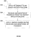
- RF energy may be applied to an energy application zone and RF feedback may be received from the energy application zone (in response to the RF energy application) during the processing of the object.
- a correlation between the RF feedback and the one or more processing states of the object may be determined (by a controller).
- Processing an object may include applying heat to the object, from a heat source.
- the controller may cause and/or control the heat application. Applying heat may include heating the object using convection heating source. Alternatively or additionally heat may be applied via IR heating. In some embodiments RF energy may be applied from an RF source to also to heat the object, optionally in addition to other heating source(s) (e.g., IR, convection, etc.).
- the controller may be configured to cause application of RF energy at a plurality of excitation setups.
- the processing state of the object may be associated with a phase of the object and/or associated with a phase of the object and/or a physical property of the object and/or a chemical property of the object.
- the one or more processing states include cooking states, for example, degree of doneness.
- the controller may further control the processing of the object based on the one or more detected processing states of the object.
- the controller may further terminate the processing of the object when the one or more processing states reach a target value.
- Computed RF feedback may include an indication of EM energy absorbability of the object.
- Computed RF feedback may include mathematical manipulation of at least two of reflected energy, coupled energy, incident energy, S parameters or input impedance.
- a display wherein the at least one controller is configured to display a representation of the one or more processing states on the display.
- the display may comprise a visual display configured to display a visual representation of the one or more processing states. Additionally or alternatively the display may comprise an audio component configured to provide an audio representation of the one or more processing states.
- the apparatus may further comprise an interface configured to receive information.
- the information received may include an indication of the processing state of the object. Additionally or alternatively the information may include at least one energy application protocol.
- the information may be recorded on a machine readable element and the interface may be configured to read the information from the machine readable element.
- a machine readable element comprising a data storage portion including one or more stored values of computed RF feedback each indicative of a processing state of the object.
- the one or more stored values may include values indicative of EM energy absorbability indicator of the object.
- a machine readable element including data indicative of instructions for at least one controller to control processing, in an energy application zone, of an object associated with the machine readable element, the instructions may be configured to cause the at least one controller to: apply energy to the energy application zone according to a first protocol and during a first time period before RF feedback received from the energy application zone meets a criterion; and apply energy to the energy application zone according to a second protocol and during a second time period after RF feedback received from the energy application zone meets the criterion.
- the data indicative of instructions may include the criterion; optionally the criterion may include a threshold value for the RF feedback. Additionally or alternatively the data indicative of instructions may include at least one of the first protocol and the second protocol. In some embodiments data may include an identity of the object and optionally the instructions may further be configured to cause the at least one controller to select the first protocol according to the identity of the object. Alternatively the instructions may be configured to cause the at least one controller to select the first protocol according to the received RF feedback.
- the instructions may further be configured to cause the at least one controller to select the first protocol according to an initial processing state of the object.
- the instructions may be configured to cause the at least one controller to determine the initial processing state of the object based on RF feedback received from the energy application zone.
- the second protocol may include terminating the EM energy application.
- the at least one of the first and second protocols may include selecting one or more excitation setups from a plurality of excitation setups, and applying RF energy at the selected one or more excitation setups and/or parameters for applying RF energy.
- the at least one of the first and second protocols is a default protocol and wherein the data indicative of instructions may comprise an instruction to use the default protocol.
- a processing state of the object that changes during EM energy application is indicated by one or more of: temperature, moisture, humidity, pressure, chemical composition, volume, weight, color, doneness level, density, taste or crispiness.
- a method and an apparatus are disclosed for controlling energy application for processing an object in an energy application zone.
- a controller may cause energy application to the energy application zone according to a first protocol during a first time period before an RF feedback received from the energy application zone may meet a criterion and then cause energy application according to a second protocol during a second time period after an RF feedback received from the energy application zone in the presence of the object meets the criterion.
- the criterion may include a threshold value for the RF feedback.
- Data indicative of instructions for processing the object may be read, from a machine readable element associated with the object, and the controller may further control the energy application according to the instructions.
- the instructions may include at least one of the first protocol and the second protocol.
- the at least one of the first and second protocols may include selecting at least one excitation setup from a plurality of excitation setups, and applying RF energy at the selected at least one excitation setup. Additionally or alternatively the at least one of the first and second protocols may include parameters for applying RF energy at a plurality of excitation setups.
- the at least one of the first and second protocol may be a default protocol and wherein the data indicative of instructions may comprise an instruction to use the default protocol.
- the criterion may be read from the machine readable element.
- the memory may be accessible via a communication network.
- An initial processing state of the object may be determined based on RF feedback received from the energy application zone. Additionally the first protocol may be selected based on the determined initial processing state of the object. Alternatively the initial processing state of the object may be determined based on data read from the machine readable element.
- the second protocol may include terminating the energy application.
- Identifying the object is disclosed.
- the first protocol may be selected according to the identity of the object.
- a machine readable element to be associated with an object to be processed in an energy application zone wherein the machine readable element may comprise data indicative of a criterion for changing RF energy application, via at least one radiating element, from a first protocol to a second protocol.
- criterion may be met when a value associated with RF feedback received from the energy application zone exceeds a threshold.
- the disclosed embodiments may involve apparatuses and methods for applying EM energy.
- EM energy includes energy deliverable by EM radiation in all or portions of the EM spectrum, including but not limited to, radio frequency (RF), infrared (IR ), near infrared, visible light, ultraviolet, etc.
- applied EM energy may include RF energy with a wavelength in free space of 100 km to 1 mm, which corresponds to a frequency of 3 KHz to 300 GHz, respectively.
- the applied EM energy may fall within frequency bands between 500 MHz to 1500 MHz or between 700 MHz to 1200 MHz or between 800 MHz to 1 GHz.
- Applying energy in the RF portion of the EM spectrum is referred herein as applying RF energy.
- Microwave and ultra high frequency (UHF) energy are both within the RF range.
- the applied EM energy may fall only within one or more industrial, scientific and medical (ISM) frequency bands, for example, between 433.05 and 434.79 MHz, between 902 and 928 MHz, between 2400 and 2500 MHz, and/or between 5725 and 5875 MHz.
- ISM industrial, scientific and medical
- Some embodiments of the invention may be related to apparatuses and methods for processing object(s), optionally by applying heat to the object, from a heat source.
- Heat may be applied to thaw a frozen object, to cook or bake a food item, to accelerate a chemical reaction, to dry objects (e.g., clothes), to sinter parts (e.g., powder parts), to cure polymers, etc.
- the heat may be applied by a convection heat source, including, for example, a heating element, such as a filament.
- the heat may be applied from an IR source, for example, an IR lamp.
- the heat may be applied from an RF source configured to supply RF energy, for example a magnetron or a solid-state power amplifier.
- two or more types of heat sources may be used to process the object.
- Two or more types of heat sources may be applied simultaneously or sequentially, or both.
- RF energy and convection heating may be applied simultaneously for part or all of the time energy is applied to process the object.
- the different energy sources may be applied alternately or consecutively. The application is not limited to any particular heat source or sources.
- RF energy may be applied to sense (i.e., detect, monitor, etc.) one or more processing states of an object before, during and/or after processing of the object.
- the processing state may be sensed (detected) by monitoring RF feedback.
- the RF feedback may be received in response to the RF energy application.
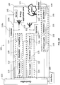
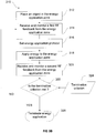
- RF energy application apparatuses for sensing one or more processing states of an object are diagrammatically presented in Figs. 1A and 1B .
- RF energy may be applied to object 103 before the processing, to detect and determine the initial state of object 103.
- RF energy may be applied to object 103 during processing, for example, in order to monitor changes in the object that occur due to the processing (e.g., heating) of the object.
- Some examples of such changes may include a phase change (e.g., thawing of a frozen object), pH change due to a progress of a reaction in a reactant solution, polymerizing of polymers due to curing, denaturation of proteins (e.g., in cooking of egg-based dishes and pastries and cooking of meat), various cooking states (e.g., baking of dough), etc.
- Those changes may be associated with one or more processing states of the object.
- the RF energy may also be applied near or at the end of the processing, for example, in order to determine if the process should be terminated.
- RF energy may be applied (e.g., in apparatus 100) to correlate between a processing state of object 103 (e.g., indicated by at least one processing state indicator) with RF feedback received from an energy application zone during processing of the object.
- a processing state indicator may include any mechanism that is configured to convey to the controller information regarding the processing state of the object.
- the processing state indicator may comprise or be one or more sensors configured to sense one or more conditions, attributes, etc. indicative of the processing state of the object, e.g., a temperature sensor, a humidity sensor etc.
- the processing state indicator may comprise or be a user interface configured to receive from a user an indication of the processing state of the object and convey this indication to the controller.
- the indication of the processing state may be sensed by one or more sensors provided in the energy application zone or may be provided by a user through an interface.
- An indication of a processing state may include any measurements of a physical or chemical properties of the object either quantitatively (e.g., temperature, pressure etc.) or non-quantitatively (e.g., color, degree of doneness, taste, cooking state, etc.) of an object before, during or after processing of the object.
- the indication of the processing state may be measured (sensed) by a sensor (e.g., sensor 140) or may be determined through inspection by a user.
- Apparatus 100 may further include a first user interface (e.g., interface 160) configured to receive from a user an indication of the processing state of the object.
- Some examples of quantitatively variable indicative of the processing state of the object may include: temperature, humidity, pressure, flow rate, pH, chemical composition, density, weight, volume, etc.
- Some examples of non-quantitatively measurable variable indicative of the processing state may include: color, taste, cooking state, doneness level etc.
- cooking state may refer to any possible state of an object, either desired or undesired, that may occur relative to a food item during any form of cooking/processing (e.g., roasting, baking, boiling, steaming, grilling, slow cooking, thawing, browning, dough proofing etc.) of the food item.
- cooking states may include: the end of baking of dough, the beginning and end of softening stage in slow cooking of meat or cooking of starchy vegetables, end of proofing of yeast dough, end of browning of various baking products, degree of doneness of various meats, or degree of any other type of cooking process, etc.
- Sensing i.e., detecting, monitoring, etc
- one or more processing states of an object may be performed by applying RF energy to an energy application zone, e.g., zone 102 in order to receive RF feedback from the object.
- the RF feedback may be correlated with the one or more processing states of the object.
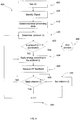
- Method 330 for correlating RF feedback and one or more processing states of the object is described in reference to Fig. 3C .
- the correlation may be recorded, for example, on a memory associated with apparatus 100 (e.g., a memory associated with controller 150) or on a machine readable element (e.g., a barcode).
- RF feedback may include any received RF signal or any value calculated based on one or more received RF signals, which may be indicative of the dielectric response of the cavity and/or the object to EM fields excited in the cavity.
- RF feedback may be excitation setup-dependent and may include, for example, values that vary over different excitation setups.
- RF feedback may include raw RF feedback and computed RF feedback.
- the raw RF feedback may include directly measurable parameters, for example, input and output power levels, field intensities, network parameters, e.g., scattering (S) parameters of the cavity, admittance (Y) parameters, reflection and transmission coefficients, impedances, etc..
- the computed RF feedback may include a result of any mathematical manipulation on two or more directly measurable parameters or values, for example, sums, multiplicative products, ratios, and/or differences between directly measurable parameters, dissipation ratio values (DR) (as discussed below), averages (e.g., time-average and/or excitation setup-average), of directly measurable parameters or of computed parameters; derivatives (e.g., time derivatives and/or excitation setup derivatives) of directly measurable parameters or of computed parameters, etc.
- DR dissipation ratio values
- averages e.g., time-average and/or excitation setup-average
- derivatives e.g., time derivatives and/or excitation setup derivatives
- RF feedback may be responsive to RF energy (i.e., EM energy in the RF range) application.
- RF energy may be applied to an energy application zone at least partially occupied by an object.
- the RF energy applied to receive the RF feedback may be at relatively low energy amounts, e.g., at a low power level.
- low energy amounts may refer to amounts of energy that result in little or no processing of an object or that are otherwise too low to provide a desired degree of a processing.
- a low energy amount may be insufficient to cause a change (or a change of a certain degree) in at least one detectable processing state of the object.
- applying RF energy to process (e.g., heat) the object may be at a first average amount of energy per excitation setup and applying RF energy to receive the RF feedback may be at a second average amount of energy per excitation setup, and the first average amount of energy per excitation set is higher than the second average amount of energy per excitation setup.
- the RF feedback may include signal(s) received in response to the RF energy application by detectors (e.g., detectors 118, 118a, 128, 138) or sensors (e.g., sensor 140) placed in or around the energy application zone.
- the signal(s) may include any or all directly measurable parameters associated with the RF energy application.
- Energy may be supplied to at least one radiating element (e.g., element 110 illustrated in Figs. 1A and IB), and energy may be reflected back from the energy application zone to the emitting radiating element in response to the application of the RF energy. Additionally or alternatively, energy may be coupled to other radiating elements (e.g., element 111 illustrated in Fig. 1A and elements 120 and 130 illustrated in Fig. 1B ).
- Various examples of RF feedback that may be received in response to RF energy application are discussed below.
- the processing of the object may be controlled based on the received RF feedback and/or the detected processing state.
- the amount of energy e.g., the temperature of a conventional cooking oven or the power level in a microwave oven
- the duration of the energy application e.g., the length of time of the energy application
- the received RF feedback e.g., computed RF feedback
- computed RF feedback may be monitored during the application of heat in a conventional oven (e.g., during baking).
- the computed RF feedback may be monitored during heating of the food item at a first temperature (e.g., 180°C) until the computed RF feedback indicate(s) that the food item has been cooked to a certain degree, after which, the heat application may be terminated.
- a first temperature e.g. 180°C
- a protocol in which energy is applied to process the object may be determined based of an RF feedback (e.g., computed RF feedback).
- a protocol may include one or more of the parameters that controls the energy application, for example, the temperature and the duration of heating in a convection heating (for example: heating at temperature T 1 for S 1 seconds followed by heating at temperature T 2 for S 2 seconds etc.), the power and the time IR heating.
- the protocol may include: setting RF energy levels (e.g., power levels and/or time durations) and/or selecting one or more excitation setups from a plurality of excitation setups, and applying RF energy at the selected excitation setups, one or more rules for energy application as a function of the RF feedback etc..
- Energy may be applied to process an object using a first protocol (e.g., temperature and time may be set to cook a food item).
- RF feedback may be monitored during the energy application until one or more RF feedback value reaches a threshold value (i.e., a first criterion) indicative of a first processing state of the object (e.g., the food item is cooked).
- a second protocol may be applied by elevating the temperature (e.g., to 220°C) for a short period of time in order to brown the food item.
- the processing e.g., heating
- the processing may be terminated (i.e., a third protocol) when the monitored RF feedback indicates that the one or more states (e.g., a second state) of processing have reached a target value or a second criterion (e.g., a desired temperature, or a desired degree of doneness, or a target pH, etc.) was met.
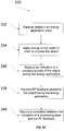
- Exemplary methods 300 and 310 for controlling energy application to an object based on RF feedback are disclosed in Figs. 3A and 3B and exemplary method 400 for controlling RF energy application based on a criterion is disclosed in Fig. 4 .
- RF energy may be applied (e.g., to sense at least one processing state of an object) in an energy application zone.
- RF energy may be applied to the energy application zone, such as energy application zone 102, illustrated in Figs. 1A and 1B .
- other energy types e.g., convection and/or IR
- Energy application zone 102 may include any cavity, void, location, region, or area where energy may be applied to process the object.
- RF energy may be applied to sense and/or detect a processing state of the object.
- the zone may be hollow, or may be filled or partially filled with liquids, solids, gases, or combinations thereof.
- energy application zone 102 may include an interior of an enclosure, interior of a partial enclosure, open space, solid, or partial solid that allows existence, propagation, and/or resonance of EM waves.
- Zone 102 may include a conveyor belt or a rotating plate.
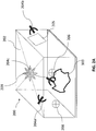
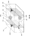
- zone 102 may include or be a cavity (for example: exemplary cavity 200 as illustrated in Fig. 2A ).
- EM energy may be applied to sense and detect a processing state of an object, e.g., object 103 in Fig. 1A , placed in the energy application zone, e.g., energy application zone 102.
- An object may be considered in the energy application zone if at least a portion of the object is located in the zone or if some portion of the object receives applied EM radiation.
- the type of object to which EM energy may be applied for processing is not limited to a particular form of the object.
- An object may include a liquid, semi-liquid, solid, semi-solid, or gas, depending upon the particular process with which the disclosed embodiment is utilized.
- the object may also include composites or mixtures of matter in differing phases.
- the term object may encompass such matter as food to be defrosted or cooked; clothes or other wet material to be dried; frozen organs to be thawed; chemicals to be reacted; fuel or other combustible material to be combusted; hydrated material to be dehydrated, gases to be expanded; liquids to be heated, boiled or vaporized, or any other material for which there is a desire to apply, even nominally, energy (e.g, EM energy).
- energy e.g, EM energy
- a portion of RF energy applied to energy application zone 102 may be absorbed (dissipated) by object 103.
- another portion of the EM energy applied to energy application zone 102 may be absorbed by various elements (e.g., food residue, particle residue, additional objects, structures associated with zone 102) or any other EM energy-absorbing materials found in zone 102 or associated with energy application zone 102.
- Energy application zone 102 may also include loss constituents that may not, themselves, absorb an appreciable amount of EM energy, but otherwise account for EM energy losses. Such loss constituents may include, for example, cracks, seams, joints, door(s), interface between cavity body and a door, or any other loss mechanisms associated with energy application zone 102.
- energy dissipated in the zone may include energy dissipated in at least a portion of object 103 along with any EM energy-absorbing constituents in the energy application zone as well as any EM energy loss constituents associated with the zone.
- Exemplary energy application zone 102 may include locations where energy is applied: an oven (e.g., a cooking oven), chamber, tank, dryer, thawer, dehydrator, reactor, engine, chemical or biological processing apparatus, pipe (e.g., fuel pipe), furnace, incinerator, material shaping or forming apparatus, conveyor, combustion zone, filter, cooler, freezer, etc.
- an oven e.g., a cooking oven
- chamber e.g., a cooking oven
- tank e.g., dryer, thawer
- dehydrator e.g., a cooking oven
- engine e.g., a chemical or biological processing apparatus
- pipe e.g., fuel pipe
- furnace e.g., incinerator
- material shaping or forming apparatus e.g., conveyor, combustion zone, filter, cooler, freezer, etc.
- the energy application zone may be part of a vending machine, in which objects are processed once purchased.
- Figs. 1A and 1B include diagrammatic representations of an apparatus 100 for applying RF energy to an object (e.g., to detect one or more processing states of the object) placed in zone 102, for example during processing of the object.
- RF energy may include EM energy applied at frequencies in the RF range.
- Apparatus 100 may include at least one radiating element 110 configured to apply RF energy to energy application zone 102.
- Radiating element 110 may include any element, system, array of elements, etc. designed or configured to transmit (emit) RF energy.
- radiating element 110 may include: any antenna, an array of antennas, an RF feed, a waveguide, a slow wave antenna, a patch antenna, inverted F antenna, etc. in any combination or numbers thereof.
- more than one antenna and/or a plurality of radiating elements may be provided (e.g., radiating elements 110 and 111 illustrated in Fig. 1A or radiating elements 110, 120 and 130 illustrated in Fig. 1B ).
- Energy application zone 102 may include an enclosure with defining surfaces.
- the radiating elements may be located on one or more of the surfaces that define zone 102 (e.g., cavity walls).
- radiating elements 110 and 130 may be located on two different (e.g., opposing) surfaces of energy application zone 102.
- one or more of the radiating elements may be located inside zone 102 (e.g., element 130) or partially located inside zone 102 (e.g., elements 110 and 111). Additionally or alternatively, a radiating element may be located outside the energy application zone (e.g., element 120). One or more of the radiating elements (e.g., element 130) may be near, in contact with, in the vicinity of or even embedded in object 103 (e.g., when the object includes a liquid, or a filter, for example - radiating element 204c illustrated in Fig. 2A ).
- each radiating element may be distinct or the same, based on a specific application, e.g., based on a desired target effect.
- Each radiating element may be positioned, adjusted, and/or oriented to emit EM waves along a same direction, or various different directions.
- the location, orientation, and configuration of each radiating element may be predetermined before applying energy to the object.
- the location, orientation, and/or configuration of each radiating element may be dynamically adjusted, for example, by using a controller (e.g., controller 150), during operation of the apparatus and/or between rounds/cycles of energy application.
- Radiating elements of any structure or configuration may be used with the disclosed embodiments.
- apparatus 100 may include at least one radiating element 110 for emitting RF energy to energy application zone 102 and at least one radiating element 111 may be configured to receive EM energy from energy application zone 102.
- a radiating element may function as an emitter, a receiver, or both, depending on a particular application or configuration.
- the radiating element acts as a receiver of RF energy from an energy application zone (e.g., received reflected and/or coupled EM waves)
- the radiating element receives RF energy from the energy application zone or from other radiating elements.
- radiating element 110 may function as emitter and receiver.
- Some aspects of the present invention may involve detecting, measuring, monitoring or sensing: RF energy emitted from the radiating element to energy application zone 102, RF energy supplied to the emitting radiating element, or RF energy received by the radiating element(s) (e.g., elements 110 and 111) from the energy application zone, to detect one or more processing states of the object.
- a detector configured to measure and/or detects and/or calculate various RF feedback of the emitted and/or received (e.g., reflected or coupled) RF energy may be associated with at least one radiating element.
- the detector may include a directional coupler associated or connected to a radiating element.
- the detector may detect and/or measure RF feedback (e.g., raw RF feedback) related to the RF energy emitted and/or received.
- the raw RF feedback may be associated with one or more processing states of the object.
- the raw RF feedback may include all detectable parameters of the RF emission, for example: power, frequency, energy, current, voltage, phases between emissions, etc.
- detector 118 illustrated in Fig. 1A , may be associated with radiating element 110 and 111.
- Detector 118 may be configured to measure or detect one or more parameters related to element 111, for example, responsive to the RF energy emission from element 110.
- detector 118 may be configured to detect the parameters of the RF energy received from zone 102 (e.g., reflected back) to element 110 as a result of the RF energy emission from element 110. Detector 118 may also include suitable types of circuits or devices that measure the voltage and current at the ports of radiating elements 110 and 111. In some embodiments, detector 118 may include a directional coupler, configured to allow signals to flow from the RF source (e.g., source 112) to the radiating elements when the radiating elements function as emitters, and to allow signals to flow from the radiating elements to the detector when the radiating elements function as receivers.
- the RF source e.g., source 112
- Detector 118 may further include a controller configured to perform mathematical manipulation of the raw RF feedback to receive (obtain) a computed RF feedback.
- the computed RF feedback may be calculated by controller 150 and the detector may send the raw RF feedback to controller 150 for further manipulation.
- detector 118 may be associated with two elements (e.g., elements 110 and 111). In some embodiments, each element may be associated with a detector. For example, elements 110, 120 and 130 may be associated with detectors 118a, 128 and 138 illustrated in Fig. 1B . Detectors 118a, 128 and 138 may be configured to detect RF energy parameters of both the emitted and the received RF energy from zone 102. For example, RF energy may be emitted from element 110 to zone 102. As a result, a portion of the RF energy may be absorbed by or dissipated in object 103, and another portion may be reflected back or coupled from zone 102 and received by elements 110, 120 and 130.
- RF energy may be supplied to one or more emitting radiating elements from RF source 112.
- Energy supplied to the emitting radiating element (e.g., element 110) from RF source 112 may be referred to as supplied energy and denoted as SE.
- Some of the supplied RF energy may be absorbed by the object (e.g., object 103). This portion of energy may be referred to as absorbed energy or dissipated energy and denoted as AE.
- a portion of the supplied RF energy may be reflected back to the emitting element (e.g., element 110). This portion of energy may be referred to as reflected energy and denoted as RE.
- the reflected energy may be reflected at the interface between the radiating element and the energy application zone. Alternatively or additionally, the reflected energy may include energy that is reflected from the energy application zone (e.g., due to impedance mismatch), for example, from the object or from a wall defining the zone, etc.
- Coupled energy may be coupled to other radiating elements or sensors in the energy application zone (for example, receiving radiating elements - e.g., element 111, another emitting radiating element (e.g., 120 and 130), a sensor (e.g., sensor 140)) and may be referred to as coupled energy and denoted as CE.
- receiving radiating elements - e.g., element 111
- another emitting radiating element e.g., 120 and 130
- a sensor e.g., sensor 140
- the supplied RF energy may include energy that is reflected (RE) back to the emitting radiating element, absorbed (AE) in the object, and coupled (CE) to one or more of other radiating element(s).
- the difference between the amount of energy supplied to a radiating element and the amount of energy reflected back to that radiating element may be referred to as delivered energy and may be denoted as DE.
- One or more detectors e.g., detector 118, 118a, 128 and 138
- a controller e.g., controller 150
- AE SE ⁇ RE + CE
- SE ⁇ RE DE AE + CE
- Apparatus 100 may further include a source for supplying RF energy to the radiating element(s).
- source 112 may supply RF energy to emitting element 110
- source 122 may supply RF energy to emitting element 120
- source 132 may supply RF energy to emitting element 130.
- an apparatus or method may involve the use of at least one source configured to supply RF energy to the energy application zone.
- a source may include any component(s) that may be suitable for generating and supplying RF energy.
- source 112 may include an RF power supply (e.g., power supply 113).
- the source may include more than one power supply (e.g., 113, 123 and 133).
- Each of the power supplies may be configured to generate EM waves that carry EM energy.
- power supply 113 (or 123 or 133) may include a magnetron configured to generate high power microwaves at a predetermined wavelength or frequency.
- power supply 113 may include a semiconductor oscillator, e.g., a voltage controlled oscillator, configured to generate AC waveforms (e.g., AC voltage or current) with a controllable frequency. The frequency may be controlled to be constant or to vary.
- AC waveforms may include sinusoidal waves, square waves, pulsed waves, triangular waves, or another type of waveforms with alternating polarities.
- a source of RF energy may include any other power supplies, e.g., EM field generator, EM flux generator, or any mechanism for generating vibrating electrons.
- the source may include a solid state amplifier.
- RF energy may be supplied to the energy application zone in the form of propagating RF waves at predetermined wavelengths or frequencies (also known as RF radiation).
- propagating RF waves may include resonating waves, traveling waves, evanescent waves, and waves that travel through a medium in any other manner.
- RF radiation carries energy that may be imparted to (or dissipated into) matter with which it interacts.
- the source (e.g., source 112, 122 or 132) includes at least one modulator (e.g., modulator 115, 125 or 135) and/or at least one amplifier (e.g., amplifier 116, 126 or 136).
- the modulator includes a phase modulator, and may include a frequency modulator, an amplitude modulator, an oscillator or any other modulator configured to modulate at least one aspect of the RF energy supplied to the radiating element.
- the amplifier may include any apparatus configured to change (e.g., amplify) the amplitude of the RF waves supplied by the power supply.
- the source e.g., source 112, 122 or 132
- the power supply, the modulator, and/or the amplifier may each be controlled by a controller (e.g., controller 150), as will be discussed in greater detail below.
- Apparatus 100 may further include at least one sensor, such as sensor 140.
- Sensor 140 may be installed in or around energy application zone 102.
- sensor 140 may constitute an exemplary processing state indicator.
- Sensor 140 may be configured to detect and/or measure RF feedback in accordance with some embodiments of the invention.
- sensor 140 may be configured to monitor the intensity of EM field excited in the energy application zone.
- sensor 140 may be configured to detect and/or measure other signals or feedback indicative of one or more processing states of the object or the energy application zone.
- sensor 140 may include a thermometer configured to measure a temperature associated with the object and/or the energy application zone (e.g., a thermocouple or an IR sensor).
- Sensor 140 may include a humidity sensor, a pressure sensor (e.g., a barometer), a pH sensor configured to measure the pH value of a solution (e.g., when the object comprises liquids), a flow meter, etc..
- Sensor 140 may be configured to measure the weight of at least a portion of the object (e.g., a scale).
- Sensor 140 may be configured to measure any detectable and measurable property (e.g., an indicator for the processing state) of the object or the energy application zone.
- Sensor 140 may be configured to send feedback signals to controller 150. In some embodiments, two or more sensor 140 may be provided.
- the two or more sensors 140 may include one or more different types or the same types of sensors (e.g., a temperature sensor, fiber optics for detecting temperature, a weight sensor, etc. may be provided). Some aspects of the invention may involve correlating, e.g., by controller 150, the signal(s) detected at sensor 140 that are indicative of the processing state of object 103, with RF feedback sensed, monitored or detected by detectors 118, 118a, 128 and/or 138, in parallel or in addition to the signal(s) received from sensor 140.
- sensors e.g., a temperature sensor, fiber optics for detecting temperature, a weight sensor, etc. may be provided.
- Some aspects of the invention may involve correlating, e.g., by controller 150, the signal(s) detected at sensor 140 that are indicative of the processing state of object 103, with RF feedback sensed, monitored or detected by detectors 118, 118a, 128 and/or 138, in parallel or in addition to the signal(s) received from sensor 140.
- apparatus 100 may include a controller (e.g., controller 150). Controller 150 may be coincident with or may be part of processor.
- processor may include an electric circuit that performs a logic operation on input or inputs.
- processor may include one or more integrated circuits, microchips, microcontrollers, microprocessors, all or part of a central processing unit (CPU), graphics processing unit (GPU), digital signal processors (DSP), field-programmable gate array (FPGA) or other circuit suitable for executing instructions or performing logic operations.
- CPU central processing unit
- GPU graphics processing unit
- DSP digital signal processors
- FPGA field-programmable gate array
- the instructions executed by the controller may, for example, be pre-loaded into a memory unit integrated with or embedded into the controller or may be stored in a separate memory unit, such as a RAM, a ROM, a hard disk, an optical disk, a magnetic medium, a flash memory, other permanent, fixed, or volatile memory, or any other mechanism capable of storing instructions for the controller.
- the separate memory unit may or may not be a part of the controller.
- the controller may be customized for a particular use, or can be configured for general-purpose use and can perform different functions by executing different software.
- controller or processor may be of similar construction, or they may be of differing constructions electrically connected or disconnected from each other. They may be separate circuits or integrated in a single circuit. When more than one controller or processor is used, they may be configured to operate independently or collaboratively. They may be coupled electrically, magnetically, optically, acoustically, mechanically or by other means permitting them to interact.
- An apparatus may include one or more RF energy application units, for example units 119, and 119a, illustrated in Figs. 1A and 1B .
- An energy application unit (e.g., unit 119a) may include one or more radiating elements, e.g., elements 110, 120 and 130, and an RF energy source supplying RF energy to the radiating element(s).
- RF energy application unit 119a may include two or more synchronized RF energy sources, e.g., sources 112, 122 and 132, which may be controlled by, for example - by controller 150, to supply to the radiating elements signals having a common frequency, at a controlled phase difference, at a controlled amplitude difference, etc.
- unit 119a may include two or more non-synchronized RF energy sources.
- the effect of applying energy from one or more of the RF energy application units in series or during non-overlapping or partially overlapping time periods may result in substantially the same as the effect as applying energy from one or more or all of the RF energy application units simultaneously.
- Embodiments consistent with the present invention may include one or more energy application units.
- An RF energy application unit may apply energy at two or more different excitation setups. Applying energy at different excitation setups may result in excitation of different field patterns in energy application zone 102.
- the excitation setups (ES) may differ from one another by one or more values of parameters that may affect the field pattern and may be controlled by controller 150. Such a parameter is referred to herein as a controllable field affecting parameter (c-FAP).
- a value may be selected for each c-FAP, and the excitation setup may be defined by the selected values. Varying a selected value of even one c-FAP may vary the excitation setup, which, in turn, may vary the field pattern excited in the energy application zone.
- varying values of c-FAPs may result in significant variations in the generated field patterns. In other instances, however, varying values of c-FAPs may produce little or no change in the generated field patterns (e.g., if the variation between the two values of the c-FAP is small).
- an RF energy application unit may be controlled from a switchboard.
- the switchboard may include a set of knobs, dials, switches, or other value-selectors, each for determining the value of (or selecting a value for) one c-FAP. Switching from one excitation setup to another may be accomplished by manipulating one (or more) of the value-selectors to select a different value.
- the position of all the value selectors collectively e.g., the positions of all the knobs, dials and switches collectively
- an RF energy application unit may be controlled by a controller, which may set the values of the available c-FAPs by using micro-switches, transistors, electronic circuitries, and other value selectors, which may look differently than knobs and dials.
- Applying energy at a particular excitation setup may excite an EM field in energy application zone 102.
- this EM field may be referred to as an excitation.
- each excitation setup may correspond to an excitation, and a reference to supply, reception, absorption, leaking, etc. of an excitation setup may refer to supply, reception, absorption, leaking, etc. of the corresponding excitation.
- a statement that a given excitation or excitation setup is absorbed in the object may mean that an EM field excited by the energy application unit (e.g., unit 119) at the given excitation setup results in energy absorbed in the object.
- controller 150 may control the frequency of an EM wave applied by energy application unit 119 to energy application zone 102.
- the frequency may be available as a controllable field affecting parameter (c-FAP).
- controller 150 may control the frequency to have any of two or more values, e.g. 800MHz, 800.5MHz, etc. By controlling the frequency and changing from one frequency value to another, the excitation setup may be changed, which, in turn, may change the field pattern excited in the energy application zone.
- the energy application unit (e.g., unit 119a) includes two radiating elements (e.g., elements 110, 120 and 130) that emit radiation at a controllable phase difference.
- the phase difference is controlled, by controller 150, to have two or more values, e.g., 0°, 90°, 180°, or 270°.
- the phase difference between EM fields emitted by the two radiating elements is available to the apparatus comprising the energy application unit as a c-FAP.
- an energy application zone may include one or more conductive elements (e.g., rods), each of which may be controlled, e.g., by controller 150, to be either in a parasitic state or in a connected state.
- the value of the state of each rod i.e. parasitic or connected
- the state of each rod may constitute a c-FAP.
- an energy application zone may include a magnetizable element (e.g., at a wall of the energy application zone) and an electromagnet near the magnetizable element.
- the magnetizable element and the electromagnet may be arranged such that a field pattern excited in the energy application zone may be affected by current flowing in the electromagnet in some embodiments, controller 150 may be configured to control the value of the current in the electromagnet (e.g., 1mA, 20mA, 500 mA, etc.).
- the value of the current may be available as a c-FAP.
- energy application unit 119a illustrated in Fig. 1B may include a plurality of radiating elements 110, 120 and 130, and each may be turned on or off.
- the status of each radiating element i.e., on or off
- the total number of radiating elements turned on may constitute a c-FAP.
- parameters that may serve as controllable field affecting parameters in some embodiments may include the position of a radiating element, orientation of a radiating element, , cavity dimensions, or any other controllable parameter, the value of which may affect the field pattern excited in the energy application zone upon RF energy application to the zone.
- Excitation setups (ES) of apparatuses configured to control only a single c-FAP may be referred to as one-dimensional excitation setups.
- An excitation setup of an apparatus that controls multiple c-FAPs may be referred to as multi-dimensional excitation setup.
- the number of c-FAPs available to an apparatus determines a dimension of the excitation setups available to the apparatus.
- the collection of all the excitations that may be excited by an apparatus (or the collection of all the excitation setups available to an apparatus) may be referred to as the excitation space of the apparatus.
- the dimension of an excitation space of an apparatus may be the same as the dimension of each excitation setup available to that apparatus.
- an RF energy application unit may be controlled by a controller (e.g., controller 150), configured to control RF energy application based on an RF feedback.
- a controller e.g., controller 150
- RF energy application when RF energy is applied to heat the object as well as to sense a processing state of the object, RF energy application may be controlled such that one or more aspects of energy application at a given excitation setup (e.g., amount of energy, power level at which energy is applied, time duration at which energy is applied etc.) may depend on RF feedback received to the same excitation, to a different excitations, or over multiple excitations.
- RF energy may be applied in an amount sufficient to process the object, i.e., in an amount sufficient to cause a change in at least one property (e.g., a processing state) of at least a portion of the object (e.g., to raise the temperature of at least a portion of the object).
- applying RF energy to process (e.g., heat) the object may proceed at a first power level (e.g., a script) and applying RF energy for purposes of generating (receiving) RF feedback may proceed at a second power level.
- the first power level is higher than the second power level.
- RF energy applied to heat the object may be at a first average amount of energy per excitation setup and RF energy applied to receive the RF feedback may be at a second average amount of energy per excitation setup, and the first average amount of energy per excitation set is higher than the second average amount of energy per excitation setup.
- the controller may be configured to select a subgroup of excitation setups (or at least one excitation setup), from all the excitation setups available to the apparatus, to apply RF energy to zone 102. Controller 150 may select a subgroup of excitation setups based on the RF feedback received at each excitation setup or at one or more excitation setups.
- the controller when RF energy is applied to process the object, the controller may be configured to determine amounts of RF energy to be applied at each excitation setup (e.g., associate RF energy amounts with each of the excitation setups), for example - based on the RF feedback.
- the controller may be configured to determine, from at least a part of the RF feedback, an absorbability indicator, (or in short, AI) at each of a plurality of excitation setups in which energy is applied to the zone.
- the controller may be configured to associate RF energy amounts with each of the excitation setups available for an apparatus based on the AI value at the respective excitation setup.
- the rules in which the controller may cause the application of RF energy to the energy application zone based on the RF feedback may be included in one or more scripts for applying RF energy to process an object.
- a script or a rule may include a decision not to supply RF energy to excitation setups associated with certain AI values, for example, those that may have AI values lower than a minimum threshold and/or higher than a maximum threshold.
- the script or the rule may include, associating the same amount of RF energy with excitation setups associated with different AI values, for example, with values in a certain range.
- the controller may associate different amounts of RF energy with excitation setups associated with different AI values.
- other rules or scripts based on the Al values and/or other RF feedback may be utilized by the controller for determining the amounts of RF energy to be applied for processing the object.
- RF energy to the zone is done by a sweep, and RF feedback may be received and associated with different excitation setups during the sweep.
- a sweep may include, for example, the application, over time, of energy at more than one excitation setup.
- a sweep may include the sequential application of energy at multiple excitation setups in one or more contiguous excitation setup group; the sequential application of energy at multiple excitation setups in more than one non-contiguous excitation setup group; the sequential application of energy at individual non-contiguous excitation setups; and/or the application of synthesized pulses having a desired excitation setup/power spectral content (e.g., a synthesized pulse in time).
- the excitation setups groups may be contiguous or non-contiguous.
- one or more controllers may regulate the energy supplied from a source (e.g., source 112) to one or more radiating elements to sequentially apply RF energy at various excitation setups to zone 102 (e.g., by switching from one c-FAP to the other) and to receive RF feedback from zone 102 associated with each excitation setup.
- a source e.g., source 112
- one or more radiating elements may sequentially apply RF energy at various excitation setups to zone 102 (e.g., by switching from one c-FAP to the other) and to receive RF feedback from zone 102 associated with each excitation setup.
- controller 150 may receive raw RF feedback indicative of the energy reflected and/or coupled at radiating elements 110, 120 and 130. Controller 150 may then determine an absorbability indicator (AI) by object 103 (i.e., a computed RF feedback) at each of a plurality of excitation setups based on the received information. Consistent with some disclosed embodiments, an absorbability indicator (AI) may include a dissipation ratio (DR) associated with each of a plurality of excitation setups. As referred to herein, a DR (or absorption efficiency or power efficiency) associated with an emitting radiating element may be defined as a ratio between EM energy absorbed by object 103 and EM energy supplied into the energy application zones by the emitting radiating element.
- DR dissipation ratio
- a DR may be defined as a ratio between EM energy absorbed by object 103 ('AE') and EM energy delivered by the emitting radiating element ('DE').
- DR may be different at different radiating elements.
- an amount of energy supplied to a particular radiating element may be determined based on the AI associated with that particular radiating element.
- an average DR for example, averaged over all transmitted excitation setups (ES), may be calculated.
- DR(ES i ) is the dissipation ratio measured when the RF energy was supplied using the i th excitation setup, and i is an integer between 1 to N wherein, N is the number of excitation setups used to apply energy to the energy application zone in a particular application.
- the average DR may vary over time.
- the computed RF feedback may include ES average of other RF feedback, for example raw RF parameters (e.g., the reflection and transmission coefficients).
- DR (or a different absorbability indicator) calculated for an excitation setup may be time dependent. RF feedback received at that excitation setup may be monitored at different occasions during the energy application (during processing) and DR (or any other computed RF feedback used for determining amounts of energy to be supplied (e.g., temperatures, power levels, durations of energy application etc.)) may be calculated at each occasion.
- the average DR may time dependent.
- the average DR may be correlated with one or more processing states of the object (e.g., the temperature of the object, the cooking state of the object, etc.).
- the average DR may be monitored during cooking (e.g., during baking) and the cooking state of the object may be determined based on the average DR.
- the correlation may be done, for example, by using a lookup table stored in memory associated with apparatus 100, comprising threshold values of the computed RF feedback (e.g., the average DR) and comparing the average DR received from the energy application zone during processing.
- the correlation between average DR and a processing state of the object may be recorded in a memory (e.g. in a lookup table, or any other suitable format).
- a processing state of the object may be determined based on RF feedback received from the object, based on input from a user, based on automated monitoring devices (IR sensors, thermometers, cameras, or any other type of sensor or detector configured to monitor at least one property or characteristic of the object being processed), or based on any other input from a monitoring source.
- the processing state of the object may then be correlated with an average DR determined for the object at various (e.g., periodic) times during processing. This correlated information may be stored.
- correlated average DR and processing state information stored in a memory may be accessed and used in processing objects.
- the controller may access a memory (either remotely located or local to the controller) and identify stored information for the same or similar type of object. The controller may then rely upon the stored information, either fully or partially, to process the particular object. That is, rather than having to monitor the processing state of the object through separate input from sensors or detectors, the controller may determine the processing state of the object by monitoring an average DR obtained from the particular object during processing, accessing the information stored in memory, and determining a processing state of the object based on the observed average DR and the stored correlation between average DR and processing state of a same or similar type of object.
- a time average of DR may be calculated while giving different weights to different excitation setups.
- some of the plotted curves may show variation in the value of DR over time (the time derivative of DR(ESi) may be higher than a threshold).
- the average DR may be calculated assigning more weight to DR(t)(ES) having larger variations than to DR(t)(ES) having lower variations (the time derivative of DR(ESi) may be lower than a threshold).
- DR(t)(ES) having lower variations may be assigned with a zero weight.
- the average DR may be calculated over time for each excitation setup.
- a reflection coefficient ⁇ may be used as an absorbability indicator of the object.
- the reflection coefficient ⁇ may be used when more than one emitting radiating element emit RF energy simultaneously.
- processing of the object may be automatically controlled based on one or more raw or computed RF feedback (e.g., DR and/or average DR).
- Energy may be applied to process the object using one or more energy application protocols.
- the protocols may include at least one of: the type of energy to be applied (e.g., convection heating, IR heating or RF heating), the amount of energy to be applied (e.g., the temperature, the power levels, amount of RF energy) and the duration of the application of each type of energy.
- the different protocols may be predetermined and stored in a memory associated with controller 150, or on a machine readable element associated with the object. Controller 150 may be configured to select an energy application protocol to be applied to process the object based on RF feedback received from the energy application zone.
- the controller may be configured to terminate the energy application and/or switch to another energy application protocol based on the received RF feedback and/or computed RF feedback.
- the RF feedback may be detected during the application of energy according to a first energy application protocol, and when a value of an RF feedback (e.g., the DR(t), the average DR(t) or time derivatives of the DR(t), and/or the average DR(t)) reaches a target value, the energy application may stop or change in at least one aspect (e.g., to a second energy application protocol). For example, the application of convection heating for baking a loaf of bread may be terminated.
- processing of the object may be controlled based on one or more other feedbacks (e.g., signals received from one or more sensors, e.g., sensor 140, provided in the energy application zone). Additionally, processing of the object may be controlled by processing instructions provided by a user, e.g., by a graphical user interface (GUI) or instructions read from a machine readable element associated with the object. The instructions may be configured to cause the at least one controller (e.g., controller 150) to control the energy application to process the object.
- GUI graphical user interface
- controller 150 may determine an RF energy application protocol by adjusting the amount of RF energy supplied at each excitation setup based on the RF feedback (e.g., RF feedback parameters).
- RF feedback may be received from energy application zone 102, e.g., during sweeping over a plurality of excitation setups.
- controller 150 may be configured to determine the amount of energy to be supplied at each excitation setup based on RF feedback received at the respective excitation setup.
- An energy application protocol may be selected to include an amount of energy determined based on RF feedback.
- an energy application protocol may dictate that amounts of energy applied at some excitation setups may be inversely related to the RF feedback values at these excitation setups (e.g., AI(ES)) calculated for the respective excitation setups. Additionally or alternatively, an energy application protocol may dictate that amounts of energy applied at an excitation setup have an inverse relationship with another RF feedback.
- RF feedback related values may include any value of RF feedback that may be received during the application of RF energy at a particular excitation setup. Additionally or alternatively, an amount of energy associated with a particular energy application protocol for application at an excitation setup may be determined according to other relationships. For example, a linear relationship between energy applied and feedback-related values may be used to determine an amount of energy to apply.
- the amount of energy determined by an energy application protocol to be applied at each excitation setup of that excitation setup subgroup may be relatively low (e.g., lower than the amounts of energy applied at any excitation setup associated with AI values below the predetermined threshold).
- the applied energy may be relatively high (e.g., higher than the amounts of energy applied at any excitation setup associated with AI values above the predetermined threshold).
- the resulting line may include a decreasing line segment.
- the decreasing line segment may have a constant slope.
- the slope of the decreasing line segment may vary.
- the slope may vary such that a multiplicative product of the AI value and amount of energy applied remains substantially constant.
- Controller 150 may be configured to hold substantially constant the amount of time at which energy is supplied to radiating elements 110, 120 and 130 at each excitation setup, while varying the amount of power supplied at each excitation setup as a function of the absorbable energy value.
- controller 150 may be configured to cause the energy to be supplied to radiating element at a particular excitation setup or excitation setups at a power level substantially equal to a maximum power level of the device and/or the amplifier at the respective excitation setup(s).
- controller 150 may be configured to vary the period of time during which energy is applied at each excitation setup as a function of the absorbable energy value. In some embodiments, both the time duration and power at which each excitation setup is applied are varied as a function of the absorbable energy value.
- Controller 150 may be further configured to control the RF energy application by controlling various aspects of the energy application units (e.g., units 119 and 119a) and RF energy source (e.g., sources 112, 122 and 132).
- energy application units e.g., units 119 and 119a
- RF energy source e.g., sources 112, 122 and 132
- the apparatus 100 includes a phase modulator (not illustrated).
- the phase modulator may be controlled to perform a predetermined sequence of time delays on an AC waveform, such that the phase of the AC waveform is increased by a number of degrees (e.g., 10 degrees) for each of a series of time periods.
- the time delays may be considered c-FAPs in apparatus 100.
- controller 150 may dynamically and/or adaptively regulate modulation based on feedback (e.g., RF feedback - for example, AI) from the energy application zone.
- controller 150 may select phases (between pairs of radiating elements) based on the EM feedback (e.g., the absorbable energy value).
- apparatus 100 may include a frequency modulator (not illustrated).
- the frequency modulator may include a semiconductor oscillator configured to generate an AC waveform oscillating at a predetermined frequency (i.e., the frequency is a c-FAP in this apparatus).
- the predetermined frequency may be associated with an input voltage, current, and/or other signal (e.g., analog or digital signals).
- a voltage controlled oscillator may be configured to generate waveforms at frequencies proportional to the input voltage.
- Controller 150 may be configured to regulate an oscillator (not illustrated) to sequentially generate AC waveforms oscillating at various frequencies within one or more predetermined frequency bands. This sequential process may be referred to as frequency sweeping. In some embodiments, based on the feedback signal provided by detector 118, controller 150 may be configured to select one or more frequencies from a frequency band, and regulate an oscillator to sequentially generate AC waveforms at these selected frequencies. In some embodiments, the frequencies may be selected based on the EM feedback (e.g., the absorbable energy values).
- the energy application unit may include more than one source of RF energy.
- more than one oscillator may be used for generating AC waveforms of differing frequencies.
- the separately generated AC waveforms may be amplified by one or more amplifiers.
- radiating elements may be caused to simultaneously emit RF waves at, for example, two or more differing frequencies (i.e., two different c-FAPs) to zone 102.
- a splitter (not illustrated) may be provided in apparatus 100 to split an AC signal e.g., a signal generated by an oscillator) into two AC signals (e.g., split signals).
- Controller 150 may be configured to regulate a phase shifter to sequentially cause various time delays such that the phase difference between two split signals may vary over time. This sequential process may be referred to as phase sweeping.
- apparatus 100 may include at least one interface 160 (for example, as illustrated in Fig. 1A or Fig.1B ). Controller 150 may be configured to receive from interface 160 one or more processing instructions and/or other information related to the object. Interface 160 may include any user interface, e.g., a GUI, a touch screen, a key pad, a screen associated with a mouse, etc. A first interface may be configured to receive from a user an indication of a processing state of the object For example, the user may indicate to the controller via the first interface that a food item has being cooked to a desired degree of doneness or reached a desired level of browning. In some embodiments.
- interface 160 may include any user interface, e.g., a GUI, a touch screen, a key pad, a screen associated with a mouse, etc.
- a first interface may be configured to receive from a user an indication of a processing state of the object For example, the user may indicate to the controller via the first interface that a food item has being cooked to a desired degree of done
- a second user interface 160 may be configured to display to a user a representation indicative of the processing state associated with the object (i.e., an image associated with the RF feedback). For example; one or more signals of sensor 140 - e.g.. the temperature of the object while processing may be displayed as graphs.
- a single interface e.g., one display
- user interface 160 may be configured to display to a user one or more RF feedback and/or computed RF feedback while processing the object.
- a third interface 160 may include a device capable of reading and receiving information (e.g., protocol(s)) from a machine readable element, for example a barcode reader, an RFID reader, etc.
- Controller 150 may be configured to receive the energy application protocol solely based on the information received from interface 160 or in combination with the RF feedback.
- the first and/or second and/or the third user interfaces are the same.
- controller 150 may be configured to determine the energy application protocol solely based on user instruction received from interface 160, e.g., a user may instruct processing information through a GUI.
- the controller may receive from the interface (e.g., from a machine readable element or from a user) a target value (i.e., a criterion) of the RF feedback (e.g., a time derivative of the average DR value) and the controller may monitor the RF feedback during the processing and terminate the processing of the object when the RF feedback reaches the target value (i.e., the criterion).
- a target value i.e., a criterion
- the controller may monitor the RF feedback during the processing and terminate the processing of the object when the RF feedback reaches the target value (i.e., the criterion).
- the user interface may include a display (not illustrated) and the controller may be further configured to display to a user the monitored RF feedback and/or a representation indicative of the processing state associated with the object. The user may then decide based on the displayed RF feedback or processing state, how to control the energy application to the object.
- the display may include any screen configured to display a visual representation to a user either graphically or by any other technique. Additionally or alternatively, the display may include an audio system configured to provide an audio representation for the user.
- the user may create a machine readable element (e.g., a barcode) based on the information provided to the user (e.g., displayed) by interface 160, for example: based on the RF feedback and/or computed RF feedback, one or more signals of seneor(s) 140, and or correlation thereof.
- a machine readable element e.g., a barcode
- the energy application protocol used and/or the RF feedback (e.g., its value(s)) correlated with one or more processing states to obtain a desired result may be recorded by the user and used for creating the machine readable element or used for future processing of the same or similar object (e.g., for automatic cooking) - for example: it may be used to create a special program in the interface for obtaining a specific result when processing the object.
- the energy application zone may be at least partially located inside a cavity.
- Cavities 200 and 210 may be exemplary energy application zones and may be part of apparatus 100.
- a cavity may include any void comprising at least one wall made from a material substantially opaque to RF energy. Any of the walls of a cavity may be made from materials opaque to RF energy.
- an oven may be constructed from cast iron, stainless steel, or aluminum alloys or other metals and alloys suitable for constructing a cavity.
- the at least one wall may comprise a dielectric material at least partially transparent to RF energy and coated by a coating made from material substantially opaque to RF energy.
- a material substantially opaque to RF energy may include any material capable of blocking or reflecting RF energy above a predetermined threshold (e.g., above 90%).
- Fig. 2A includes a diagrammatic representation of a cavity 200 in accordance with some embodiments.
- Cavity 200 may include cavity body 202.
- Cavity body 202 may be configured to hold at least a portion of an object (e.g., object 103).
- Cavity body 202 may comprise at least one wall constructed from or coated by, a material substantially opaque to RF energy.
- Cavity body 202 may have a rectangular shape (as illustrated), cylindrical shape, or may have any other suitable shapes.
- cavity body 202 may take a shape of a cooking oven for cooking food, a cylindrical tank for processing liquids, an industrial furnace for curing polymers or sintering parts, a pipe comprising flowing fluids and/or gasses, etc.
- Cavity 200 may further comprise at least one radiating element.
- cavity 200 may include three (or more) radiating elements 204a, 204b, and 204c as illustrated in Fig. 2A . Any or all of radiating elements 204a, 204b, or 204c may constitute examples consistent with any of the radiating element described herein.
- Radiating elements 204a, 204b, and 204c may include any elements configured to emit and/or receive RF energy from the cavity (e.g., to detect a processing state of the object).
- the radiating elements may be connected to an RF source (e.g., source 112 illustrated in Fig. IB), to a detector configured to detect one or more RF feedback (e.g., detector 118a in Fig.
- Radiating elements may be installed in proximity to at least one cavity wall (for example, element 204a).
- a radiating element may be installed outside the cavity (for example, element 204b), in proximity to a cavity wall having an RF transparent window 205.
- RF transparent window 205 may be constructed from any dielectric material capable of transferring at least a portion of the RF energy emitted from element 204b to cavity 200.
- a radiating element may be located in proximity to or at least partially inside object 103 (for example, element 204c).
- element 204c may be immersed in a solution in a chemical reactor or a beer in a brewery tank, element 204c may also be embedded in a filter or a catalytic convertor in order to heat the filter or the converter.
- radiating elements 204a, 204b, and 204c may be part of one or more energy application units (not illustrated) - (e.g., unit 119 or 119a).
- cavity 200 may include at least one sensor, such as sensors 206 and 208, which may be similar to sensor 140 described above. Sensors 206 and 208 may constitute exemplary processing state indicators. Sensor 206 may be embedded in, immersed in or placed in proximity to object 103. Sensor 206 may include any sensor configured to measure a property (e.g., an indication of the processing state) of object 103. The property may include a measurable property, such as temperature, pressure, volume, pH, humidity ratio, density, moisture, etc. Additionally or alternatively, the property may include other characteristics, such as color, taste, doneness, smell, etc. In some embodiments, one or more properties may be monitored (e.g., detected) by sensor 206.
- sensors 206 and 208 may constitute exemplary processing state indicators. Sensor 206 may be embedded in, immersed in or placed in proximity to object 103. Sensor 206 may include any sensor configured to measure a property (e.g., an indication of the processing state) of object 103. The property may include a measurable property, such as temperature,
- sensor 206 may be configured to measure RF feedback (e.g., raw RF feedback parameters) detected in cavity 200.
- sensor 206 may be configured to measure the intensity of the EM field excited in cavity 200 by the radiating element(s).
- sensor 208 may be installed in proximity to or on at least one wall in cavity 200.
- Sensor 208 may include any sensor configured to measure a property (e.g., an attribute, condition, etc. indicative of the processing state) of object 103 or cavity 200. Similar to sensor 206, sensor 208 may sense one or more properties associated with object 103 and/or the surrounding environment of the object. In some embodiments, sensors 206 and 208 may be configured to sense the same or similar properties.
- sensors 206 and 208 may sense different properties. For example, sensor 206 may sense the temperature of the object, and sensor 208 may sense humidity in cavity 200 in the vicinity of object 103. Sensors 206 and 208 may be in communication with a controller (e.g., controller 150). In some embodiments, processing of the object (e.g., energy application) may be controlled in accordance with one or more signals sensed by sensor 206 and/or 208.
- a controller e.g., controller 150
- processing of the object e.g., energy application
- processing of the object may be controlled in accordance with one or more signals sensed by sensor 206 and/or 208.
- cavity 200 may further include at least one energy (heat) source 209.
- Source 209 may be configured to apply energy (e.g., heat) to cavity 200 to process object 103.
- Source 209 may include any convection heating source, for example: a filament, hot air impingement, gas flame, or any other heating element configured to apply heat to an object by convection means.
- source 209 may include IR lamp configured to apply IR radiation to object 103.
- energy may be applied to process the object from two different sources.
- source 209 may apply heat (convection or IR) and at least one of radiating elements 204a, 204b and/or 204c may apply RF energy to process the object as well and/or to detect a processing state of the object by receiving RF feedback from the object.
- Source 209 may apply the energy (e.g., heat), and the at least one radiating element may additionally apply RF energy to process the object, simultaneously, consecutively, or a combination of both.
- energy for processing the object may be applied solely from source 209, and the radiating elements may apply RF energy to detect the processing state of the object.
- Fig. 2B illustrates an exemplary cavity according to some embodiments of the invention.
- Cavity 210 may include, for example, one or more of the components shown in Fig. 2A .
- Cavity 210 may include cavity body 212.
- Cavity body 212 may comprise at least one wall constructed from a material substantially opaque to RF energy.
- Cavity 210 may have any shape or size allowing holding of at least a portion of an object.
- Cavity 210 may further include at least one radiating element configured to emit and/or receive RF energy from cavity body 212, optionally more than one radiating element (e.g., 3 elements 204d, 204e and 204f) may be installed in cavity 210.
- 3 elements 204d, 204e and 204f may be installed in cavity 210.
- Each of elements 204d, 204e and 204f may be connected to a detector (e.g., detector 118a illustrated in Fig. 1B ) and may be in communication with a controller (e.g., controller 150) configured to receive signals related to RF feedback from the detectors connected to elements 204d, 204e and 204f.
- Radiating elements 204d, 204e, and 204f may be part of one or more energy application units (not illustrated) - (e.g., unit 119 or 119a).
- the RF feedback (e.g., computed RF feedback) received from elements 204d, 204e and 204f, may be indicative of a processing state of the object.
- Elements 204d, 204e and 204f may be located on or in proximity to cavity body 212 walls. Each element may be located on a different wall. Additionally or alternatively, more than one radiating element may be located on the same wall. The invention is not limited to any particular radiating elements configuration. Elements 204d, 204e and 204f may be any radiating elements according to the embodiments of the invention (e.g., elements 110, 111 etc.). Elements 204d, 204e and 204f may be located in volume 216 between cavity body 212 walls and at least one partition 214. Optionally, more than one partition 214 (e.g., 2 partitions illustrated in Fig. 2B ) may be installed in cavity 210.
- more than one partition 214 e.g., 2 partitions illustrated in Fig. 2B
- Partitions 214 may be constructed from a material at least partially transparent to RF energy. Additionally or alternatively, at least one partition 214 may include at least one window consisting of a material at least partially transparent to RF. Some examples of materials transparent to RF energy may include: various glasses, polymers and some ceramics and their composites. Partitions 214 may separate inner volume 215 and one or more of radiating elements 204d, 204e and 204f. Elements 204d, 204e and 204f may be installed in at least one outer volume 216. Inner volume 215 may be configured to hold at least a portion of an object (e.g., object 103) and partitions 214 may be configured to separate the object from the radiating elements.
- an object e.g., object 103
- the energy application zone may be located at least partially within inner volume 215.
- partitions 214 may protect elements 204d, 204e and 204f from water and oil vapors extracted from the meat or the chicken during cooking.
- the object may include a chemical solution to be reacted, and inner volume 215 may be a chemical reactor.
- partitions 214 may protect elements 204d, 204e and 204f from a corrosive attack by the chemical solution.
- cavity 210 may further include tray 218.
- Tray 218 may be located in volume 215, separating volume 215 into two parts each capable of holding different object(s). Tray 218 may be at least partially transparent to RF energy, allowing at least a portion of the energy applied from the two upper radiating elements 204d and 204e to enter the lower part of cavity 210 and vice versa with respect to the lower radiating element 204f.
- Tray 218 may comprise a heat resistant polymer, for example Silicone, Teflon, etc.
- Tray 218 may comprise glass (e.g., tempered soda-lime glass also known as Pyrex) or ceramic material.
- Tray 218 may be substantially opaque to RF energy, blocking much or all of the RF energy emitted from elements 204d and 204e from enter the lower part of cavity 210, and vice versa .
- Tray 218 may comprise any metallic material, including, for example, various stainless steels, cast iron, aluminum based alloys, cupper based alloys etc.
- cavity 210 may further include one or more energy (heat) sources 209a and 209b, similar to source 209 illustrated and disclosed in respect to Fig. 2A .
- Source 209b may be located to apply energy (e.g., heat) to the lower portion of volume 215, and source 209a may be located to apply energy (e.g., heat) to the upper portion of volume 215.
- energy may be applied to process object(s) placed in either or both portions of volume 215, from sources 209a and 209b, and RF energy may be applied from radiating element 204d, 204e and 204f (e.g., to process (heat) the object and/or to detect processing state(s) of the object).
- Method 300 for controlling energy application to an energy application zone based on RF feedback in accordance with some embodiments of the invention is presented in the flowchart in Fig. 3A .
- Method 300 may include applying RF energy to an energy application zone, to detect a processing state of an object placed in an energy application zone, during processing of the object.
- Method 300 may be performed by controller 150, using apparatuses 100.
- RF energy may be applied to the energy application zone (e.g., zone 102 and cavities 200 and 210), in step 302, via one or more radiating elements.
- the RF energy may be applied, during the processing of the object, in order to detect RF feedback (e.g., computed RF feedback).
- RF energy may be applied at one or more excitation setups.
- the RF energy may be applied for example every 1 second, 3 seconds, 5 seconds or 10 seconds, or other periods of time.
- the object may be processed by applying energy (e.g., in convection or IR).
- energy e.g., in convection or IR
- low amounts of RF energy may initially be applied at one or more excitation setups.
- Low RF amounts of energy may be defined as amounts of energy applied to the energy application zone that result in little or no processing of an object (e.g., object 103) placed in the zone.
- the low amounts of energy may not be sufficient to: cook a food item, thaw frozen object, cause or accelerate chemical reaction, etc.
- Low amounts of energy may be applied by for example, by applying low RF power from the RF source (e.g., source 112) or by applying high power for very short period of time.
- RF energy application in step 302 may be conducted at energy levels sufficient to process an object placed in the energy application zone by a certain degree.
- the RF energy application in step 302 is conducted by sweeping over a plurality of excitation setups available in apparatus 100.
- a controller e.g., controller 150
- the controller may then receive or detect, and optionally monitor, RF feedback from the energy application zone, in step 304.
- the RF feedback may be detected (received) in response to the RF energy application.
- the RF feedback may include a result of the RF energy applied in step 302.
- the RF feedback may be received from one or more sensors and/or detectors configured to measure raw RF feedback in the energy application zone optionally at each of the applied excitation setup.
- the received raw RF feedback may be processed to determine a computed RF feedback - for example by conducting mathematical manipulation of raw RF feedback parameters or values received from the energy application zone, for example: the computed RF feedback may include: a DR, an average DR, a time derivative of any of the signals, etc.
- the computed RF feedback may be correlated with one or more processing states of the object.
- Method 330 for recording e.g., on a memory associated with controller 150 or on a machine readable element
- a correlation between an RF feedback value (or a computed RF feedback) and a processing state of an object is disclosed in Fig. 3C .
- the correlation recording may be done during heating of an exemplar of the object (e.g., object 103) being heated.
- the exemplar object may comprise at least some of the characteristics of the heated object.
- the recorded correlation may be used to control energy application to the object (e.g., object 103).
- the computed RF feedback may be monitored to detect a processing state of the object, for example by comparing the recoded correlation (e.g., stored as a look up table) and the received computed RF feedback (e.g., one or more values of the computed RF feedback).
- the controller e.g., controller 150
- the controller may monitor at least one computed RF feedback parameter (e.g., DR, average DR, time derivative of ⁇ , etc.) before, during or after processing (e.g., heating) of the object.
- the controller may compare the at least one monitored computed RF feedback parameter (e.g., its value) with a correlated computed RF feedback (value) recorded and stored for example in a lookup table.
- the correlation received may be used to determine the one or more processing states of the object.
- the correlation may be recorded and stored on a memory associated with the controller or on a machine readable element associated with the object and the controller may be configured to receive the correlation between the RF feedback and the processing state of the object from the memory and/or the machine readable element.
- the correlated computed RF feedback (e.g., one or more values) may be collected during processing of another object that may be representative to the object processed.
- the raw RF feedback may be sensed or detected every 1 second, 3 seconds, 5 seconds or 10 seconds, or at any other desired time period.
- Various RF feedbacks may be received by the controller during the application of RF energy at various excitation setups, for example, during sweeping over a plurality of excitation setups.
- the controller may be configured to associate some or all of the RF feedback (e.g., its values) with a corresponding excitation setup.
- the computed RF feedback received in step 304 may be indicative of the initial state of the object.
- An exemplary initial state of the object may comprise a frozen object, a deeply frozen (e.g., below a threshold temperature) object, an object at room temperature or in general the initial temperature of the object before processing, different defrosting states, volume of an object, number of pieces or items associated with the object or objects, the position of each item in a package, etc.
- the RF feedback (e.g., the computed RF feedback) may be correlated with one or more processing states of the object. The correlation may be determined in accordance with method 330.
- the controller may detect one or more processing states of the object based on the monitored RF feedback (e.g., the computed RF feedback).
- the controller may display or otherwise provide the detected processing state(s) to the user (e.g., via interface 160).
- the user may provide instructions configured to cause the at least one processor to process the object based on the provided processing state(s).
- the controller may control the processing of the object by applying energy based on the received and optionally monitored RF feedback. For example, the controller may cause application of energy when the computed RF feedback values received from the energy application zone include values lower or higher than a threshold. Additionally or alternatively, when the object is processed by RF energy, the controller may adjust the RF energy amounts applied at each excitation setup as a function of the computed RF feedback at that excitation setup. In some embodiments, the controller may terminate the process when the computed RF feedback (its value) reached or is below a predetermined threshold.
- the process may repeat and RF energy may be applied to detect the processing state of the object during and/or after the energy application.
- Steps 302 and 304 may be repeated and the processing may be re-adjust in step 306 based on the computed RF feedback received in step 304.
- steps 302 and 304 may be performed several times while processing the object - e.g., every 3 or 5 seconds.
- an energy application protocol may be set based on the RF feedback (e.g., a computed RF feedback) received from the energy application zone.
- Method 310 presented in the flowchart in Fig. 3B may comprise placing an object (e.g., object 103) in an energy application zone (e.g., zone 102), in step 312.
- Method 310 may be performed by controller 150, using apparatuses 100.
- RF energy may be applied to the energy application zone to detect a processing state of the object by receiving and monitoring a first RF feedback (e.g., computed RF feedback) for example, by controller 150, in step 314.
- the RF feedback received in step 314 may be indicative of the initial state of the object.
- the detected initial state may be displayed to the user (e.g., through an interface).
- the RF energy may be applied at a plurality of excitation setups, for example, by sweeping over at least a portion of available excitation setups, and the RF feedback may be received and associated with each of the applied excitation setups, as disclosed above with respect to steps 302 and 304 in method 300.
- the received RF feedback (e.g., one or more values or trend - for example: when the value changes from increasing to decreasing over time) may be correlated with one or more processing states of the object as discussed above.
- a controller may set or determine an energy application protocol, in step 316.
- the user may set (select) the energy application protocol in response to the displayed initial state (e.g., the user may select a protocol from a plurality displayed protocols).
- the interface may send the energy application protocol to controller.
- An energy application protocol may include one or more rules at which energy may be applied to the energy application zone. The rules may include setting the amount of energy to be applied (e.g., temperature, power levels energy application durations) or the type of energy (e.g., RF energy, IR energy or convection heating) based on the received RF feedback.
- the controller may set a rule for an oven to apply 180° for 30 minutes.
- the rules may control the selection of the excitation setups, from the plurality of excitation setups, at which RF energy may be applied. Additionally or alternatively, the rules may determine the amount of energy to be applied at each excitation setup, for example, by setting the amounts of power and/or time supplied to each radiating element (e.g., element 110, 120 and 130) from the RF energy source (e.g., source 112, 122 and 132).
- the energy application protocol may be set based on one or more RF feedbacks.
- Energy may be applied to the energy application zone to process the object according to the energy application protocol set in step 316, in step 318.
- the energy may be applied via one or more heat sources (e.g., source 209, 209a and 209b).
- source 209 may include a filament in a cooking oven, where the oven may include a thermostat and may be configured to heat the oven to 180°C for 30 minutes.
- RF energy may be applied to process the object via radiating elements connected to one or more RF sources.
- the energy source and/or RF source may be controlled by the controller to apply the energy according to the set protocol.
- a second RF feedback (e.g., a computed RF feedback) may be received and optionally monitored (while processing the object) from the energy application zone to detect processing state(s) of the object after or during the energy application (step 320).
- the processing state(s) may be displayed to the user (e.g., through an interface) during the processing.
- the second type of RF feedback may be similar to the first type of RF feedback.
- the second type of RF feedback may be different from the first type of RF feedback.
- the first computed RF feedback received in step 314 indicating that the yeast dough was fully proofed may include the DR
- the second computed RF feedback indicating that the yeast dough is fully baked may include a time derivative of the average DR.
- the values of the second RF feedback may be compared to a value available to the controller, e.g., a termination criterion, in step 322.
- the termination criterion may include at least one RF feedback value (e.g., a computed RF feedback value) correlated with a processing state of the object, e.g., the final desired state of the object.
- the termination criterion may be recorded and stored in: a memory associated with the controller, on a data indicative of instruction included in a machine readable element (e.g., a barcode tag or an RFID tag) or sent to the controller from a remote location connected to the controller (e.g., the Internet), in step 324.
- the termination criterion may include a single value of the average DR, a set of values of DR(ESi), a set of values of S 11 (ESi), a single value of DR at a particular excitation setup (ES), the time derivative of the power reflected from the zone, the time derivative of the DR(ESi) etc.
- a value associated with the second RF feedback is substantially equal to the termination criterion, e.g., when the dough is completely baked, (step 322-YES)
- the energy may be terminated in step 326 and the processing of the object placed in the energy application zone may be ended.
- the second RF feedback value is not equal to the termination criterion (step 322-NO)
- the process may return to step 314 and repeats until the termination criterion is met.
- more than one termination criterion may be used in the RF energy application and the controller may cause application of the energy until all criteria are met, at least two criteria are met, etc.
- a first protocol may apply 40°C to proof a yeast dough, may be set according to RF feedback, set as a default or predetermined prior the RF energy application.
- the first protocol may be terminated when a first criterion, for example the criteria that the dough is fully proofed, may be met.
- the first protocol may be followed by a second EM application protocol (e.g., bake the dough at 180 °C for 30 minutes) and a second criterion (e.g., dough is baked), until a termination criterion may be applied.
- a second EM application protocol e.g., bake the dough at 180 °C for 30 minutes
- a second criterion e.g., dough is baked
- Method 330 for correlating and optionally recording a processing state of an object, indicated by at least one processing state indicator, with an RF feedback received during the processing of the object is presented in the flowchart in Fig. 3C , in accordance with some embodiments of the invention.
- Method 330 may be performed by controller 150, using apparatuses 100.
- An apparatus for recording a correlation of a processing state of an object, indicated or received by at least one processing state indicator, with RF feedback (e.g., one or more values or RF feedback or computed RF feedback) received from an energy application zone during processing of the object in the energy application zone may include one or more components discussed in reference to Figs. 1A-1B and 2A-2B and may employ method 330.
- the apparatus may further be configured to create a machine readable element to be associated with an object.
- Method 330 may be performed on a test object, and the recorded correlation may be used to process similar or identical object.
- Method 330 may be performed in order to create a machine readable element or a processing program (e.g., cooking program) to be associated with objects similar or identical to the test object.
- An object to be processed may be placed in an energy application zone (e.g., zones 102 and cavities 200 and 210), in step 332.
- the user may provide additional information regarding the test object - e.g., its type (for example: a cake, a steak etc.), size, position of the object in the cavity (e.g., a tray level in multi-level ovens).
- the additional information may be read from a machine readable element associated with the test object.
- Energy may be applied to the object to process the object, in step 334.
- sources 209, 209a and/or 209b may apply convection heating to bake a cake placed in a cooking oven.
- energy may be applied in accordance with instructions provided by the user (e.g., the user may indicate a desired amount of energy to be absorbed in the object (KJ) or may provide a desired temperature of a convection heating).
- An indication of a processing state (e.g., a chemical or physical property or a cooking state) of the object may be received during (i.e., before, during and after) the energy application, in step 336.
- the indication of the processing state of the object may be received from various processing state indicators, for example, sensors configured to sense a variable indicative of the processing state of the object placed in or around the energy application zone, e.g., sensors 140, 206 and 208.
- the processing state sensed by the sensors may be displayed to a user.
- the indication of the processing state of the object may be received from a user and the processing state indicator may comprise a first user interface configured to receive from a user an indication of the processing state of the object (e.g., the degree of doneness, a desired color, etc.,). Controller 150 may record the indication of the processing state of the object.
- the controller may record a temperature signal from a thermometer indicating the temperature inside a steak (e.g., when the steak's temperature has reached 50°C and the steak reached a medium doneness level).
- the controller may record a weight, e.g., received from a scale, of berries placed in a drying cabinet to be dried. In some circumstances, the weight may indicate that the berries have lost a certain amount of water.
- RF feedback may be received from at least one detector configured to detect the RF feedback from the energy application zone (step 338).
- RF energy is applied by sweeping over a plurality of excitation setups to the energy application zone.
- the RF energy may be emitted from the radiating elements (e.g., elements 110, 120, 130, 204a-204f) and reflected back or coupled to the radiating elements.
- an RF feedback may be received from the energy application zone and recorded (e.g, one or more values) by controller 150, during the processing of the object.
- controller 150 may record the values of the DR at each excitation setup and/or the average DR over all excitation setups as a function of time.
- the values of DR may be monitored during the some or all of the processing of the object.
- the RF feedback received by the detector(s) and/or the computed RF feedback may be displayed to a user.
- the user may evaluate the process (e.g., the user may evaluate the processing state and compare this to a desired processing state).
- an additional test object may be processed with a different instructions - e.g., different energy protocols etc.
- the user may indicate (e.g., via interface) that a desired results was obtained.
- an indication whether the desired result was obtained may be indicated by one or more sensors (processing state indicators) provided in the apparatus.
- the program e.g., the one or more energy protocols
- the program may be displayed to a user for approval before recording it (e.g., on a machine readable element).
- the RF feedback (e.g., one or more values or trends) may be correlated with the indication of object processing state (e.g., one or more signals received by processing state indicator) and the correlation may be recorded, in step 340.
- the controller may correlate the recorded indication of the processing state and the RF feedback as the feedback is obtained (at the same time, at different times, or at some later time).
- the recorded correlation(s) may be used to detect one or more processing states of the object and may set a criterion/criteria for controlling the energy application to process object(s) similar to the test object.
- the temperature measurements of the object may be correlated to average DR values and the average DR correlated to a desired target temperature may be set as a criterion and may be recorded in a data storage portion included in machine readable element.
- one or more of the RF feedback (e.g., values) may be correlated to at least one processing state of the object and may be recorded and stored in data indicative of instructions included in a machine readable element, and/or on a memory associated with the controller and/or in a remote location connected to the controller.
- a machine readable element may be associated with an identification number (e/g/. tag ID) and the recorded data may be stored on a remote location such that the identification number may be associated with that data.
- Fig. 4 is a flowchart of a method 400 for controlling energy application based on a criterion, for example the criterion disclosed in step 340 of method 330, according to some embodiments of the invention.
- a controller e.g., controller 150
- Method 400 may include switching between two or more energy protocols based on a detected criterion.
- the criterion may be associated with a processing state of the object or an associated RF feedback (e.g., computed RF feedback).
- the controller may identify the object to be processed based on identity information received from an interface, at step 404.
- An interface e.g., interface 160
- An interface may include a system configured to read data recorded on a machine readable element, for example, a tag reader (e.g., a barcode reader or an RFID reader), and the identity of the object may be coded or recorded on the tag (e.g., a machine readable element such as a barcode, etc.).
- the identity of the object may be received from a user using any user interface 160 (e.g., GUI, touchpad, keypad, touch-screen etc.) configured to receive instruction(s) from a user and forward the instruction(s) to a controller.
- the initial processing state of the object may be determined, in step 410.
- the controller may determine the initial processing state of the object based on the identity of the object.
- the controller may correlate between the identity of the object and the initial processing state of the object.
- the identity of the object may define the chemical composition and reaction mixture concentration in a solution introduced to a chemical reactor.
- the initial processing state may be recorded on a machine readable element associated with the object, and the controller may be configured to receive a data indicative of the initial processing state of the object (e.g., instructions) from the machine readable element.
- a code printed on an instant cake powder package may identify the initial conditions of a cake powder mixture after adding the liquids (e.g., milk) and eggs at room temperature and after molding (in the cake mold) and made ready to be introduced to the cooking oven.
- the instructions recorded on the machine readable lements are further configured to cause the at least one controller (e.g., controller 150) to determine the initial condition of the object based on RF feedback received from the energy application zone.
- the initial processing state of the object may be determined based on an RF feedback received from the energy application zone holding the object.
- the initial conditions of the object may be determined by monitoring RF feedback.
- Value(s) of RF feedback received from the energy application zone (as a response to RF energy application) at the initial state of the object may be compared to RF feedback values recorded on a media accessible to the controller, for example a machine readable element, a memory associated with the controller, etc.
- the recorded RF feedback values may be correlated to at least one initial processing state of the object.
- a first protocol, comprising energy application parameters, may be determined in step 420.
- the first protocol may be determined based on the initial processing sate of the object determined in step 410.
- the determined first energy application protocol may comprise RF energy application parameters that may thaw the object, e.g., 'thawing script', for example using RF energy.
- the initial processing state may indicate the temperature of the frozen object, and the first protocol may comprise energy application parameters for example, temperature and time in a convection oven.
- the energy applied to process the object is RF energy - the protocol may include energy level, power level, time duration and/or selecting of one or more excitation setups from a plurality of excitation setups, and applying RF energy at the selected excitation setups, for thawing the object starting at the indicated temperature.
- the first protocol (e.g., protocol (i)) may be determined based on data indicative of instructions recorded on a machine readable element or in a memory accessible to the controller.
- the data indicative of instructions recorded on a machine readable element may include instructions configured to cause a controller to select the first protocol according to the initial processing state of the object or RF feedback received from the energy application zone.
- one or more protocols may be included in data indicative of instructions recorded on the machine readable elements, and the controller may determine the protocol(i) from data recorded on the readable element.
- the data may include some or all of the energy application parameters and/or a code associated with some or all of the energy application parameters.
- the machine readable element or the memory may include processing instructions for processing the object.
- the instructions may include more than one protocol, and/or data related with the protocol, and/or data related with the initial processing state of the object.
- the protocol when RF energy is further applied to process the object, the protocol may include a correlation between RF feedback values (e.g., computed RF feedback values) and the RF energy to be applied to the energy application zone. The correlation may be recorded on a readable element (e.g., bar-code), and all the other energy application parameters may be set regardless of the information in the machine readable element.
- the processing parameters included in the protocol(i) e.g., the first protocol
- the data indicative of instructions comprises an instruction to use the default protocol.
- the at least one correlation may be set such that the energy applied to the energy application zone may accelerate a chemical reaction in a chemical reactor.
- a different correlation may be set (e.g., recorded on a readable element) if the protocol is designed to puff un-puffed dough, taken from a refrigerator at 4°C.
- Other correlations can be set depending on the requirements of a particular application.
- the protocol is checked to determine whether the protocol is an energy application protocol or a termination protocol.
- An energy application protocol may be defined as any protocol that includes application parameters for controlling non- zero energy delivery to the energy application zone.
- a termination protocol may be defined a protocol involving application of zero energy to the energy application zone. If the protocol is a termination protocol (422: YES), the process ends (442). Otherwise, step 424 may be performed, and energy (e.g., RF energy, IR energy, convection heating energy, etc.) may be applied to the energy application zone according to protocol(i) (e.g., the first protocol) determined in step 420.
- energy e.g., RF energy, IR energy, convection heating energy, etc.
- the protocol may include a correlation between a computed RF feedback and the RF energy to be applied to the energy application zone, and in performing step 424, the computed RF feedback may be calculated from one or more values of an RF feedback, and energy may be applied accordingly.
- the protocol may include other energy application parameters.
- an RF feedback is received from the energy application zone, optionally in the presence of the object.
- the RF feedback may be monitored during energy application in accordance with protocol (i) (e.g., the first protocol).
- the feedback may include any RF feedback, either raw RF feedback parameters and/or computed RF feedback.
- the feedback may include: the S parameters, DR, average DR, input impedance of radiating element(s), power detected in the energy application zone, their respective derivatives, averages, etc.
- the received RF feedback (e.g., its value(s)) may be checked (compared) against a criterion - criterion(i), e.g. to see if the criterion is met.
- the criterion may be or may be correlated to a processing state of the object. This step may be carried out during the energy application or in an intermission in energy application. Meeting the criterion may be checked continuously during the energy application, or intermittently, e.g. periodically, for example, every 1 sec or 5 sec or 10 sec, etc. Additionally or alternatively, the RF feedback may be checked against the criterion upon occurrence of certain events.
- the RF feedback may be compared to the criterion when an indication indicative of the object's temperature shows a temperature change larger than 1°C, when an indication indicative of the object's humidity changes by a predetermined amount, every predetermined number of sweeps, etc.
- the criterion may include one or more RF feedback (e.g., values) correlated with at least one processing state of the object.
- the criterion may be set according to method 330, disclosed in the flowchart at Fig. 3C .
- the criterion may be recorded on a data storage portion in a machine readable element, on a memory associated with the controller or on a remotely located media accessible to the controller.
- the controller may receive the criterion from the machine readable element and/or the memory and/or the media.
- step 420 may be repeated, and the energy may be applied to the energy application zone according to the protocol(i+1) during a second time period after RF feedback received from the energy application zone meets criterion(i) (repeating step 424).
- protocol(i+1) e.g., a second protocol
- step 420 may be repeated, and the energy may be applied to the energy application zone according to the protocol(i+1) during a second time period after RF feedback received from the energy application zone meets criterion(i) (repeating step 424).
- Cooking experiments for correlating a cooking state of a food item with an RF feedback were conducted in an experimental cooking oven.
- the cooking oven included similar components as disclosed in Figs. 1B and 2A : a controller, a convection heat source, two radiating elements each contacted to an RF source and a detector, and a temperature sensor.
- a ready-to-bake frozen pizza was defrosted and cooked by applying convection heating at 180°C.
- the temperature of the pizza and the average DR were detected and monitored as function of the cooking time.
- a sharp change in the slope (the time derivative) of the average DR was detected when the pizza was thawed and a change in the sign of the time derivative (from positive to negative) was observed when the pizza was fully backed.
- Fig.5 presents two measurements of the average DR (an example of a computed RF feedback) taken from two different radiating elements, during baking experiments of a vanilla cake.
- An instant vanilla cake mixture was prepared according to the instructions on the mixture package and placed in the same experimental cooking oven used to bake the pizza. The oven was heated to 180°C.
- the average DR was monitored by the controller every 3 seconds, and the baking state of the cake was monitored visually by a chef periodically.
- the entire baking time was approximately 30 minutes.
- the x axis in Fig. 5 is the number of the average DR detection cycles taken every 3 seconds. At the first 350 cycles (17.5 minutes) the average DR increased with time and has a positive time derivative.
- Another baking experiment using a frozen pizza was conducted using apparatus and methods according to some embodiments of the invention.
- the baking experiments were performed in an experimental RF cooking oven (an oven that employs RF energy for processing, e.g., cooking, food objects) comprising two radiating elements.
- a frozen ready-to-bake pizza at a temperature of -18°C (deepfreeze) weighing 500 grams and having a diameter of 30 cm was placed in the experimental RF cooking oven.
- an RF feedback of the average DR i.e., a computed RF feedback
- the results of the monitored average DR and the monitored temperature are presented in the graphs of Fig. 6A .
- the temperature divided by 100 (i.e. T[°C]/100) in the center of the pizza is presented in graph 630, and the temperature divided by 100 at the edge of the pizza is presented in graph 640.
- the average DR measured and calculated for the first and second radiating elements are presented in graphs 610 and 620.
- the RF energy application protocols are illustrated as line 650.
- a first protocol was chosen to be a "thawing protocol" based on the initial processing state of the pizza.
- the protocol parameters for applying RF energy were: using frequencies between 800-1000 MHz, supplying energy (SE) to the radiating elements of the RF cooking oven as a function of the DR at each frequency, according to the thawing protocol presented in Fig. 6B . No energy was applied to frequencies associated with a DR higher than 0.7. Monitoring the temperature showed thawing (i.e., a processing state of the object) of the edge part of the pizza after 20 sec and the inner part of the pizza after 120 sec.
- SE energy
- the change in the derivative of the average DR may be correlated to a "thawing state" and may be used as a criterion for changing from thawing protocol to baking protocol.
- a 'baking protocol' was applied using frequencies between 800-1000 MHz, supplying energy to the radiating elements as function of the DR(f) (the dissipation ratio as a function of the frequency) according to the protocol presented in Fig. 6C .
- the maximum available energy was applied at all frequencies associated with a DR lower than 0.7, and a linear correlation between the DR and SE were applied at frequencies associated with DR higher than 0.7.
- the end of baking was indicated by a user (e.g., a chef) based on the color of the topping cheese (i.e., a processing state of the pizza), which became slightly brown when the average DR reached a value of 0.6.
- the average DR value of 0.6 may be correlated to an end of baking state of a pizza and may be used as a criterion for terminating the RF energy application when the pizza is fully cooked.
- a thawed, unbaked pizza weighing 500 grams and having a diameter of 30 cm at room temperature was placed in an experimental RF cooking oven.
- an RF feedback of the average DR was monitored together with the temperature of the pizza at two locations, one in the center (denoted as ch2) and the other at the edge of the pizza (denoted as ch1).
- the results of the monitored average DR and the monitored temperature are presented in the graphs of Fig. 7 .
- the pizza was indicated as being ready and fully baked when the temperature exceeded 85 [deg]C, after approximately 240 sec.
- the average DR started to rise after 240 sec, and the derivative of the average DR changed from negative to positive.
- the change in the derivative may be correlated with the baking state of the pizza and may be used as a criterion for applying the RF energy termination protocol.
- Figs. 8A and 8B are illustrations representing two optional machine readable elements comprising a data indicative of instructions (the instructions being configured to cause the at least one controller to control the energy application to process the object) recorded on each element, in accordance with some embodiments of the invention.
- Fig. 8A illustrates a general data indicative of instructions that includes various protocols (e.g., at least a first protocol and a second protocol) and criteria.
- Fig 8B includes an exemplary recorded element with data indicative of instructions for preparing a pizza.
- the instructions may include a step for determining the initial processing state of the pizza and a thawing protocol (for example, a protocol presented in Fig. 6B ) if the pizza is frozen.
- the instructions may further include a criterion for determining if the pizza is thawed and a cooking protocol (for example, a protocol presented in Fig. 6C ) for cooking the pizza.
- the instructions may include a criterion for determining if the pizza is ready, such as, for example, a change in the derivative of the average DR, as disclosed with respect to Fig 7 .
- the instructions may also include a termination protocol.
- a machine e.g., a controller
- a task e.g., configured to cause application of a predetermined field pattern
- the machine performs this task during operation.
- a task is described as being done in order to establish a target result (e.g., in order to apply a plurality of EM field patterns to the object)
- carrying out the task may accomplish the target result.
- predetermined means only that the associated quantity or value is calculated or otherwise determined beforehand.
- Predetermined values may include values stored in memory; values calculated, observed, measured, read into, received, etc. before commencement of EM energy processing; or any values calculated, observed, measured, read into, received, etc. during such processing.
Claims (20)
- Procédé pour appliquer de l'énergie radiofréquence (RF) pour détecter un état de traitement d'un objet (103) placé dans une cavité (102) pendant un traitement de l'objet, le procédé consistant :à appliquer, par une pluralité d'éléments rayonnants, de l'énergie RF à l'objet pendant un traitement en fournissant de l'énergie RF à la cavité sous la forme d'ondes résonantes ;dans lequel l'application de l'énergie RF comprend un balayage sur une pluralité de valeurs d'un paramètre qui affecte des configurations de champ dans la cavité, dans lequel le balayage comprend un changement d'une différence de phase entre deux éléments rayonnants de la pluralité d'éléments rayonnants ;à recevoir des signaux de rétroaction à la suite de l'application de l'énergie RF, à utiliser lesdits signaux pour obtenir une rétroaction calculée, corrélée à un ou plusieurs états de traitement de l'objet ;à surveiller la rétroaction calculée pendant le traitement ; età comparer la rétroaction calculée avec une rétroaction enregistrée associée à un état de traitement d'un objet donné à titre d'exemple pour détecter l'état de traitement de l'objet, dans lequel l'objet donné à titre d'exemple est représentatif de l'objet qui doit être traité, et dans lequel la rétroaction enregistrée a été enregistrée pendant le chauffage de l'objet donné à titre d'exemple lorsque l'objet donné à titre d'exemple se trouvait dans l'état de traitement.
- Procédé selon la revendication 1, consistant à recevoir une corrélation entre la rétroaction calculée et l'état de traitement de l'objet (103) en provenance d'une mémoire associée à un dispositif de commande (150).
- Procédé selon l'une quelconque des revendications 1 à 2, consistant à recevoir la corrélation entre la rétroaction calculée et l'état de traitement de l'objet (103) en provenance d'un élément lisible par une machine associé à l'objet.
- Procédé selon l'une quelconque des revendications précédentes, dans lequel le traitement de l'objet (103) consiste à appliquer de la chaleur à l'objet.
- Procédé selon la revendication 4, dans lequel l'application de la chaleur consiste à chauffer l'objet (103) par le biais d'un chauffage par convection, d'un chauffage à infrarouge (IR), ou à la fois par le biais d'un chauffage par convection et d'un chauffage à infrarouge.
- Procédé selon l'une quelconque des revendications 4 à 5, dans lequel l'application de la chaleur consiste à appliquer de l'énergie RF pour chauffer l'objet (103).
- Procédé selon l'une quelconque des revendications précédentes, dans lequel le ou les états de traitement sont associés :à une phase de l'objet (103) ; et/ouà une propriété physique de l'objet ; et/ouà une propriété chimique de l'objet.
- Procédé selon l'une quelconque des revendications précédentes, dans lequel l'objet (103) est un aliment et le ou les états de traitement comprennent des états de cuisson.
- Procédé selon l'une quelconque des revendications précédentes, consistant à commander le traitement de l'objet (103) en se basant sur le ou les états de traitement détectés de l'objet.
- Procédé selon l'une quelconque des revendications précédentes, dans lequel les signaux de rétroaction indiquent une absorption d'énergie électromagnétique (EM) par l'objet (103).
- Procédé selon l'une quelconque des revendications précédentes, consistant à mettre fin au traitement de l'objet (103) lorsque le ou les états de traitement atteignent une valeur cible.
- Procédé selon la revendication 1, dans lequel l'état de traitement de l'objet (103) correspond à une condition initiale de l'objet.
- Appareil pour appliquer de l'énergie RF, par le biais d'un élément rayonnant, pour détecter un état de traitement d'un objet (103) placé dans une cavité (102), pendant un traitement de l'objet, l'appareil comprenant :une unité d'applications d'énergie RF (119), configurée pour appliquer de l'énergie RF à l'objet en fournissant de l'énergie RF à la cavité sous la forme d'ondes résonantes afin de générer une rétroaction RF, dans lequel l'unité d'applications d'énergie RF comprend une pluralité d'éléments rayonnants ; etun dispositif de commande (150) configuré :pour provoquer une application d'énergie RF par l'unité d'applications d'énergie RF, dans lequel l'application de l'énergie RF comprend un balayage sur une pluralité de valeurs d'un paramètre qui affecte des configurations de champ dans la cavité, dans lequel le balayage comprend un changement d'une différence de phase entre deux éléments rayonnants de la pluralité d'éléments rayonnants ;pour recevoir des signaux de rétroaction à la suite de l'application de l'énergie RF, pour utiliser lesdits signaux pour obtenir une rétroaction calculée, corrélée à un ou plusieurs états de traitement de l'objet ;pour surveiller la rétroaction calculée pendant le traitement ; etpour comparer la rétroaction calculée avec une rétroaction enregistrée associée à un état de traitement d'un objet donné à titre d'exemple pour détecter l'état de traitement de l'objet, dans lequel l'objet donné à titre d'exemple est représentatif de l'objet qui doit être traité, et dans lequel la rétroaction enregistrée a été enregistrée pendant le chauffage de l'objet donné à titre d'exemple lorsque l'objet donné à titre d'exemple se trouvait dans l'état de traitement.
- Appareil selon la revendication 13, dans lequel le dispositif de commande (105 40) est en outre configuré pour provoquer une application d'une énergie pour traiter l'objet (103).
- Appareil selon la revendication 13 ou 14, dans lequel le dispositif de commande (105 40) est configuré pour provoquer l'application d'une énergie RF à l'objet pendant un traitement.
- Appareil selon l'une quelconque des revendications 13 à 15, comprenant en outre un détecteur (118) configuré pour détecter les signaux de rétroaction et dans lequel le détecteur est associé à un élément rayonnant (110, 111) inclus dans l'unité d'application d'énergie (119).
- Appareil selon l'une quelconque des revendications 13 à 16, comprenant une source de chaleur (209, 209a, 209b) pour appliquer de la chaleur pour traiter l'objet (103).
- Appareil selon la revendication 17, dans lequel la source de chaleur (209, 209a, 209b) comprend une source de chauffage par convection, une lampe infrarouge ou à la fois une source de chauffage pas convection et une lampe infrarouge.
- Appareil selon la revendication 17, dans lequel la source de chaleur comprend une source RF (112).
- Appareil selon l'une quelconque des revendications 13 à 19, dans lequel le dispositif de commande (150) est configuré pour commander le traitement en se basant sur l'état de traitement détecté.
Priority Applications (1)
| Application Number | Priority Date | Filing Date | Title |
|---|---|---|---|
| EP19150833.2A EP3503680B1 (fr) | 2011-08-31 | 2012-08-30 | Détection de l'état d'un traitement d'objets à l'aide d'un rayonnement rf |
Applications Claiming Priority (3)
| Application Number | Priority Date | Filing Date | Title |
|---|---|---|---|
| US201161529361P | 2011-08-31 | 2011-08-31 | |
| US201261612961P | 2012-03-19 | 2012-03-19 | |
| PCT/US2012/053044 WO2013033330A2 (fr) | 2011-08-31 | 2012-08-30 | Détection d'état de traitement d'objet à l'aide de rayonnement rf |
Related Child Applications (2)
| Application Number | Title | Priority Date | Filing Date |
|---|---|---|---|
| EP19150833.2A Division-Into EP3503680B1 (fr) | 2011-08-31 | 2012-08-30 | Détection de l'état d'un traitement d'objets à l'aide d'un rayonnement rf |
| EP19150833.2A Division EP3503680B1 (fr) | 2011-08-31 | 2012-08-30 | Détection de l'état d'un traitement d'objets à l'aide d'un rayonnement rf |
Publications (3)
| Publication Number | Publication Date |
|---|---|
| EP2752086A2 EP2752086A2 (fr) | 2014-07-09 |
| EP2752086B1 EP2752086B1 (fr) | 2019-01-09 |
| EP2752086B2 true EP2752086B2 (fr) | 2021-12-08 |
Family
ID=47040776
Family Applications (2)
| Application Number | Title | Priority Date | Filing Date |
|---|---|---|---|
| EP12773420.0A Active EP2752086B2 (fr) | 2011-08-31 | 2012-08-30 | Détection d'état de traitement d'objet à l'aide de rayonnement rf |
| EP19150833.2A Active EP3503680B1 (fr) | 2011-08-31 | 2012-08-30 | Détection de l'état d'un traitement d'objets à l'aide d'un rayonnement rf |
Family Applications After (1)
| Application Number | Title | Priority Date | Filing Date |
|---|---|---|---|
| EP19150833.2A Active EP3503680B1 (fr) | 2011-08-31 | 2012-08-30 | Détection de l'état d'un traitement d'objets à l'aide d'un rayonnement rf |
Country Status (6)
| Country | Link |
|---|---|
| US (4) | US20130080098A1 (fr) |
| EP (2) | EP2752086B2 (fr) |
| JP (1) | JP6087358B2 (fr) |
| KR (1) | KR20140058646A (fr) |
| CN (2) | CN105722263B (fr) |
| WO (1) | WO2013033330A2 (fr) |
Families Citing this family (115)
| Publication number | Priority date | Publication date | Assignee | Title |
|---|---|---|---|---|
| EP3048862B1 (fr) * | 2008-11-10 | 2019-10-16 | Goji Limited | Dispositif et procédé de contrôle d'énergie |
| WO2011058538A1 (fr) | 2009-11-10 | 2011-05-19 | Goji Ltd. | Dispositif et procédé de chauffage par énergie rf |
| CN103039123B (zh) | 2010-05-03 | 2015-09-30 | 高知有限公司 | 空间受控能量递送 |
| EP2958399B1 (fr) | 2010-07-01 | 2019-10-09 | Goji Limited | Traitement d'objets par énergie à fréquence radio (rf) |
| US9992824B2 (en) | 2010-10-29 | 2018-06-05 | Goji Limited | Time estimation for energy application in an RF energy transfer device |
| US9414442B2 (en) * | 2010-11-29 | 2016-08-09 | Goji Limited | System, apparatus, and method for cooking using RF oven |
| JP6087358B2 (ja) | 2011-08-31 | 2017-03-01 | ゴジ リミテッド | Rf放射を使用した対象物の処理状態の検知 |
| US9161390B2 (en) | 2012-02-06 | 2015-10-13 | Goji Limited | Methods and devices for applying RF energy according to energy application schedules |
| US20130269537A1 (en) | 2012-04-16 | 2013-10-17 | Eugenio Minvielle | Conditioning system for nutritional substances |
| US8490862B1 (en) * | 2012-04-16 | 2013-07-23 | Eugenio Minvielle | Transformation system for nutritional substances |
| US20130269538A1 (en) | 2012-04-16 | 2013-10-17 | Eugenio Minvielle | Transformation system for nutritional substances |
| US9541536B2 (en) | 2012-04-16 | 2017-01-10 | Eugenio Minvielle | Preservation system for nutritional substances |
| US10219531B2 (en) | 2012-04-16 | 2019-03-05 | Iceberg Luxembourg S.A.R.L. | Preservation system for nutritional substances |
| WO2013140266A2 (fr) | 2012-03-19 | 2013-09-26 | Goji Ltd. | Application d'énergie radiofréquence en fonction des variations d'un retour électromagnétique dans le temps |
| US9414623B2 (en) | 2012-04-16 | 2016-08-16 | Eugenio Minvielle | Transformation and dynamic identification system for nutritional substances |
| US8733631B2 (en) | 2012-04-16 | 2014-05-27 | Eugenio Minvielle | Local storage and conditioning systems for nutritional substances |
| US9702858B1 (en) | 2012-04-16 | 2017-07-11 | Iceberg Luxembourg S.A.R.L. | Dynamic recipe control |
| US9528972B2 (en) | 2012-04-16 | 2016-12-27 | Eugenio Minvielle | Dynamic recipe control |
| US20140069838A1 (en) | 2012-04-16 | 2014-03-13 | Eugenio Minvielle | Nutritional Substance Label System For Adaptive Conditioning |
| US9171061B2 (en) | 2012-04-16 | 2015-10-27 | Eugenio Minvielle | Local storage and conditioning systems for nutritional substances |
| US9436170B2 (en) | 2012-04-16 | 2016-09-06 | Eugenio Minvielle | Appliances with weight sensors for nutritional substances |
| US9460633B2 (en) | 2012-04-16 | 2016-10-04 | Eugenio Minvielle | Conditioner with sensors for nutritional substances |
| US9564064B2 (en) | 2012-04-16 | 2017-02-07 | Eugenio Minvielle | Conditioner with weight sensors for nutritional substances |
| US9429920B2 (en) | 2012-04-16 | 2016-08-30 | Eugenio Minvielle | Instructions for conditioning nutritional substances |
| US10470255B2 (en) | 2012-07-02 | 2019-11-05 | Goji Limited | RF energy application based on electromagnetic feedback |
| WO2014024044A1 (fr) * | 2012-08-06 | 2014-02-13 | Goji Ltd. | Procédé permettant de détecter une décharge obscure et dispositif utilisant le procédé |
| EP2896088B1 (fr) | 2012-09-13 | 2019-05-08 | Goji Limited | Four rf avec antenne f inversée |
| WO2014188422A2 (fr) | 2013-05-21 | 2014-11-27 | Goji Ltd. | Etalonnage d'un système de traitement rf |
| EP3014951A1 (fr) * | 2013-06-28 | 2016-05-04 | Koninklijke Philips N.V. | Procédé et dispositif de traitement de produits alimentaires congelés |
| CN105325055A (zh) * | 2013-06-28 | 2016-02-10 | 皇家飞利浦有限公司 | 用于处理冷冻食物的方法和设备 |
| WO2015052145A1 (fr) * | 2013-10-07 | 2015-04-16 | Goji Limited | Appareil et méthode de détection et de traitement par rf |
| EP3131411B1 (fr) * | 2014-03-17 | 2017-12-13 | Koninklijke Philips N.V. | Commander un processus de cuisson d'aliments |
| WO2015155638A1 (fr) * | 2014-04-07 | 2015-10-15 | Indesit Company S.P.A. | Système permettant de réchauffer et/ou de cuire des aliments et comportant une détection des micro-ondes |
| GB201411342D0 (en) * | 2014-06-26 | 2014-08-13 | Rolls Royce Plc | Wireless communication system |
| WO2016001260A1 (fr) * | 2014-06-30 | 2016-01-07 | Goji Limited | Chauffage d'objets par énergie en micro-ondes |
| WO2016038039A1 (fr) * | 2014-09-11 | 2016-03-17 | Koninklijke Philips N.V. | Commande d'un processus de cuisson de nourriture |
| EP3195695A4 (fr) | 2014-09-17 | 2018-05-16 | Whirlpool Corporation | Chauffage direct par antennes à plaques |
| RU2693933C2 (ru) * | 2014-12-17 | 2019-07-08 | Конинклейке Филипс Н.В. | Способ и аппарат для определения информации о размере пищевых ингредиентов |
| CN104654381B (zh) * | 2015-02-12 | 2017-08-04 | 广东美的厨房电器制造有限公司 | 半导体微波炉及用于微波炉的半导体功率源 |
| EP3266281B1 (fr) | 2015-03-06 | 2021-04-21 | Whirlpool Corporation | Procédé d'étalonnage d'amplificateur haute puissance pour un système de mesure de puissance radioélectrique |
| KR20170137830A (ko) * | 2015-04-10 | 2017-12-13 | 덴마크스 텍니스케 유니버시테트 | 마이크로파 전력 센서 조립체를 포함하는 의료 제제 용기 |
| EP3284317A1 (fr) * | 2015-04-16 | 2018-02-21 | Goji Limited | Commande de phase automatique |
| US10904962B2 (en) | 2015-06-03 | 2021-01-26 | Whirlpool Corporation | Method and device for electromagnetic cooking |
| US10368692B2 (en) | 2015-09-01 | 2019-08-06 | Husqvarna Ab | Dynamic capacitive RF food heating tunnel |
| US11284742B2 (en) | 2015-09-01 | 2022-03-29 | Illinois Tool Works, Inc. | Multi-functional RF capacitive heating food preparation device |
| EP3400755A1 (fr) | 2016-01-08 | 2018-11-14 | Whirlpool Corporation | Procédé et appareil de détermination de stratégies de chauffage |
| EP3400756B8 (fr) | 2016-01-08 | 2020-02-26 | Whirlpool Corporation | Séparateur isolé pour four à micro-ondes à plusieurs cavités |
| EP3409076B1 (fr) | 2016-01-28 | 2020-01-15 | Whirlpool Corporation | Procédé et appareil permettant de fournir une énergie électromagnétique radiofréquence pour cuire des aliments |
| WO2017133916A1 (fr) * | 2016-02-04 | 2017-08-10 | Koninklijke Philips N.V. | Appareil de détection et dispositif de cuisson l'utilisant |
| CN108702817B (zh) | 2016-02-15 | 2021-09-10 | 松下电器产业株式会社 | 用于传送射频电磁能量以对食料进行烹调的方法和装置 |
| EP3446544A1 (fr) * | 2016-04-20 | 2019-02-27 | Vorwerk & Co. Interholding GmbH | Système de préparation et procédé de fonctionnement d'un système pour la préparation d'au moins un aliment |
| EP3280225B1 (fr) * | 2016-08-05 | 2020-10-07 | NXP USA, Inc. | Appareil de dégivrage avec réseau d'adaptation inductif localisé et leurs procédés de fonctionnement |
| EP3280224A1 (fr) * | 2016-08-05 | 2018-02-07 | NXP USA, Inc. | Appareil et procédés de détection d'achèvement de l'opération de dégivrage |
| CN110495250B (zh) | 2016-08-09 | 2021-06-18 | 卓缤科技贸易公司 | 射频处理设备和方法 |
| CN106255251B (zh) * | 2016-08-31 | 2022-11-18 | 广东美的厨房电器制造有限公司 | 微波检测电路及包含该微波检测电路的微波炉 |
| WO2018056977A1 (fr) | 2016-09-22 | 2018-03-29 | Whirlpool Corporation | Procédé et système de distribution d'énergie électromagnétique radiofréquence |
| WO2018075030A1 (fr) | 2016-10-19 | 2018-04-26 | Whirlpool Corporation | Système et procédé de préparation d'aliments au moyen de modèle multicouche |
| EP3530074A4 (fr) | 2016-10-19 | 2020-05-27 | Whirlpool Corporation | Modulation de temps de cuisson de charge d'aliment |
| EP3530075A4 (fr) | 2016-10-19 | 2020-05-27 | Whirlpool Corporation | Procédé et dispositif de cuisson électromagnétique à l'aide d'une commande en boucle fermée |
| US10602573B2 (en) | 2016-11-18 | 2020-03-24 | Nxp Usa, Inc. | Establishing RF excitation signal parameters in a solid-state heating apparatus |
| ES2767721T3 (es) * | 2016-11-22 | 2020-06-18 | Miele & Cie | Procedimiento para calentar un líquido detectando un punto de ebullición |
| US11026535B2 (en) * | 2016-11-30 | 2021-06-08 | Illinois Tool Works Inc. | Oven with machine learning based algorithm selection strategy |
| US10728962B2 (en) * | 2016-11-30 | 2020-07-28 | Illinois Tool Works, Inc. | RF oven energy application control |
| US11197355B2 (en) | 2016-12-22 | 2021-12-07 | Whirlpool Corporation | Method and device for electromagnetic cooking using non-centered loads |
| WO2018118066A1 (fr) | 2016-12-22 | 2018-06-28 | Whirlpool Corporation | Procédé et dispositif de cuisson électromagnétique faisant appel à une gestion de charges non centrée au moyen d'une rotation d'axe spectromodale |
| US11452182B2 (en) | 2016-12-29 | 2022-09-20 | Whirlpool Corporation | System and method for detecting changes in food load characteristics using coefficient of variation of efficiency |
| US11503679B2 (en) | 2016-12-29 | 2022-11-15 | Whirlpool Corporation | Electromagnetic cooking device with automatic popcorn popping feature and method of controlling cooking in the electromagnetic device |
| WO2018125149A1 (fr) * | 2016-12-29 | 2018-07-05 | Whirlpool Corporation | Dispositif de cuisson électromagnétique à fonctionnement par fusion automatique et procédé de commande de cuisson dans le dispositif de cuisson électromagnétique |
| WO2018125136A1 (fr) | 2016-12-29 | 2018-07-05 | Whirlpool Corporation | Système et procédé de commande d'une distribution de chauffage dans un dispositif de cuisson électromagnétique |
| US11483906B2 (en) * | 2016-12-29 | 2022-10-25 | Whirlpool Corporation | System and method for detecting cooking level of food load |
| EP3563636B1 (fr) | 2016-12-29 | 2021-10-13 | Whirlpool Corporation | Système et procédé de commande de puissance d'un dispositif de cuisson |
| US11412585B2 (en) | 2016-12-29 | 2022-08-09 | Whirlpool Corporation | Electromagnetic cooking device with automatic anti-splatter operation |
| US11638333B2 (en) | 2016-12-29 | 2023-04-25 | Whirlpool Corporation | System and method for analyzing a frequency response of an electromagnetic cooking device |
| EP3563635B1 (fr) | 2016-12-29 | 2022-09-28 | Whirlpool Corporation | Dispositif de cuisson électromagnétique à chauffage automatique de liquide et procédé de contrôle de la cuisson dans le dispositif de cuisson électromagnétique |
| EP3563631B1 (fr) | 2016-12-29 | 2022-07-27 | Whirlpool Corporation | Détection de modifications dans des caractéristiques de charge alimentaire en utilisant le facteur q |
| WO2018125146A1 (fr) | 2016-12-29 | 2018-07-05 | Whirlpool Corporation | Dispositif de cuisson électromagnétique à détection automatique d'ébullition et procédé de commande de cuisson dans le dispositif de cuisson électromagnétique |
| US11013357B2 (en) * | 2017-03-06 | 2021-05-25 | Illinois Tool Works Inc. | Modified S-parameter measurement and usage in solid state RF oven electronics |
| CN106895452A (zh) * | 2017-03-22 | 2017-06-27 | 北京小米移动软件有限公司 | 微波炉加热控制方法和装置 |
| CN109000399A (zh) * | 2017-06-06 | 2018-12-14 | 青岛海尔股份有限公司 | 用于解冻装置的解冻方法及冰箱 |
| CN108991340A (zh) * | 2017-06-06 | 2018-12-14 | 青岛海尔股份有限公司 | 用于解冻装置的解冻方法 |
| TWI636251B (zh) * | 2017-06-23 | 2018-09-21 | 中原大學 | 熱特性量測裝置 |
| CN111201835A (zh) * | 2017-08-15 | 2020-05-26 | 高知有限公司 | 六端口功率测量 |
| US20190059133A1 (en) * | 2017-08-16 | 2019-02-21 | The Markov Corporation | Sensors for Training Data Acquisition in an Intelligent Electronic Oven |
| EP3451794A1 (fr) | 2017-09-01 | 2019-03-06 | Whirlpool Corporation | Croustillance et brunissement dans un four à micro-ondes plat complet |
| US11039510B2 (en) | 2017-09-27 | 2021-06-15 | Whirlpool Corporation | Method and device for electromagnetic cooking using asynchronous sensing strategy for resonant modes real-time tracking |
| CN109729610A (zh) * | 2017-10-30 | 2019-05-07 | 上海集迦电子科技有限公司 | 一种带有荧光温度传感器的射频加热系统及射频加热器 |
| US10917948B2 (en) * | 2017-11-07 | 2021-02-09 | Nxp Usa, Inc. | Apparatus and methods for defrosting operations in an RF heating system |
| US10771036B2 (en) | 2017-11-17 | 2020-09-08 | Nxp Usa, Inc. | RF heating system with phase detection for impedance network tuning |
| US10785834B2 (en) | 2017-12-15 | 2020-09-22 | Nxp Usa, Inc. | Radio frequency heating and defrosting apparatus with in-cavity shunt capacitor |
| EP3503679B1 (fr) | 2017-12-20 | 2022-07-20 | NXP USA, Inc. | Dispositif de dégivrage et ses procédés d'utilisation |
| DE102018202519B4 (de) * | 2018-02-20 | 2023-05-25 | BSH Hausgeräte GmbH | Verfahren zum Betreiben eines Haushaltsgeräts mit Auftaufunktion und Haushaltsgerät zum Durchführen des Verfahrens |
| DE102018202719A1 (de) * | 2018-02-22 | 2019-08-22 | BSH Hausgeräte GmbH | Verfahren zum Betreiben eines Lebensmittel-Erwärmungsgeräts sowie Lebensmittel-Erwärmungsgerät |
| US10772165B2 (en) | 2018-03-02 | 2020-09-08 | Whirlpool Corporation | System and method for zone cooking according to spectromodal theory in an electromagnetic cooking device |
| EP3547801B1 (fr) | 2018-03-29 | 2022-06-08 | NXP USA, Inc. | Dispositif de dégivrage et ses procédés d'utilisation |
| CN108670049B (zh) * | 2018-04-26 | 2022-03-04 | 青岛海尔智能技术研发有限公司 | 射频加热设备的加热食物方法 |
| US11404758B2 (en) | 2018-05-04 | 2022-08-02 | Whirlpool Corporation | In line e-probe waveguide transition |
| WO2019225412A1 (fr) * | 2018-05-21 | 2019-11-28 | パナソニックIpマネジメント株式会社 | Dispositif de traitement à micro-ondes |
| US10912160B2 (en) | 2018-07-19 | 2021-02-02 | Whirlpool Corporation | Cooking appliance |
| DE102018213963B4 (de) * | 2018-08-20 | 2020-06-18 | Werner & Pfleiderer Industrielle Backtechnik Gmbh | Teigling-Form, Teigbearbeitungsverfahren unter Verwendung einer Mehrzahl von Teigling-Formen sowie Teigbearbeitungsanlage zum Durchführen des Verfahrens |
| US10952289B2 (en) | 2018-09-10 | 2021-03-16 | Nxp Usa, Inc. | Defrosting apparatus with mass estimation and methods of operation thereof |
| US11800608B2 (en) | 2018-09-14 | 2023-10-24 | Nxp Usa, Inc. | Defrosting apparatus with arc detection and methods of operation thereof |
| CN109619121A (zh) * | 2018-11-13 | 2019-04-16 | 容小明 | 一种电磁发热的烤肉炉判断所烤肉的生熟程度的方法 |
| CA3120385A1 (fr) * | 2018-11-19 | 2020-05-28 | Goji Limited | Four de sechage de cannabis |
| US11166352B2 (en) | 2018-12-19 | 2021-11-02 | Nxp Usa, Inc. | Method for performing a defrosting operation using a defrosting apparatus |
| US11229094B2 (en) * | 2018-12-20 | 2022-01-18 | Nxp Usa, Inc. | Combined RF and thermal heating system and methods of operation thereof |
| US11039511B2 (en) | 2018-12-21 | 2021-06-15 | Nxp Usa, Inc. | Defrosting apparatus with two-factor mass estimation and methods of operation thereof |
| CN109519982A (zh) * | 2018-12-28 | 2019-03-26 | 广东美的厨房电器制造有限公司 | 烹饪设备 |
| US11289946B2 (en) * | 2019-04-08 | 2022-03-29 | Purdue Research Foundation | Method and system of uniform wireless power distribution within a chamber |
| US11324084B2 (en) | 2019-05-16 | 2022-05-03 | Nxp Usa, Inc. | Combined RF and thermal heating system with heating time estimation |
| CN110290611B (zh) * | 2019-06-06 | 2022-04-08 | 恩智浦美国有限公司 | 加热电器的检测器 |
| US11696374B2 (en) * | 2019-06-19 | 2023-07-04 | Illinois Tool Works Inc. | Solid state RF oven with context awareness |
| CN111031619A (zh) * | 2019-12-27 | 2020-04-17 | 珠海格力电器股份有限公司 | 多腔体微波炉的加热的方法、装置、微波炉及存储介质 |
| CN113131205B (zh) * | 2019-12-31 | 2023-08-15 | 重庆品胜科技有限公司 | 低旁瓣rfid天线及通信设备 |
| EP4110014A4 (fr) * | 2020-02-21 | 2023-08-16 | Panasonic Intellectual Property Management Co., Ltd. | Dispositif de traitement haute fréquence |
| US11585764B1 (en) * | 2021-12-09 | 2023-02-21 | Applied Materials, Inc. | Multi-level RF pulse monitoring and RF pulsing parameter optimization at a manufacturing system |
Citations (1)
| Publication number | Priority date | Publication date | Assignee | Title |
|---|---|---|---|---|
| EP1021067A2 (fr) † | 1999-01-14 | 2000-07-19 | Samsung Electronics Co., Ltd. | Procédé de fonctionnement d'un four à micro-ondes |
Family Cites Families (100)
| Publication number | Priority date | Publication date | Assignee | Title |
|---|---|---|---|---|
| US3192642A (en) | 1961-11-06 | 1965-07-06 | Gen Electric | Automatic fabric drying machine and control means |
| US3439431A (en) | 1967-12-15 | 1969-04-22 | Gen Electric | Microwave dryer control circuit |
| DE2004497C3 (de) | 1970-01-31 | 1974-01-17 | Licentia Patent-Verwaltungs-Gmbh, 6000 Frankfurt | Wäschetrokner mit rotierender Trommel, wobei zur Feuchtemessung der Wäsche ein Hochfrequenzoszillator verwendet wird |
| US4297557A (en) * | 1976-05-03 | 1981-10-27 | Robertshaw Controls Company | Microwave oven temperature indicator and control means |
| CA1081796A (fr) | 1978-02-09 | 1980-07-15 | B. Alejandro Mackay | Fours a micro-ondes a chauffage controle utilisant differentes frequences de travail |
| JPS54134479A (en) * | 1978-04-10 | 1979-10-18 | Sharp Corp | Wireless temperature measuring device |
| JPS5533783A (en) | 1978-08-31 | 1980-03-10 | Sharp Kk | Cooking device heating source controller |
| US4340796A (en) * | 1978-08-31 | 1982-07-20 | Sharp Kabushiki Kaisha | Wireless temperature-sensing system inclusive of thermally-responsive oscillator |
| LU81706A1 (fr) | 1978-09-22 | 1980-01-24 | Ass Eng Ltd | Joints d'etancheite interfaciaux a jeu positif |
| CA1138937A (fr) | 1978-11-24 | 1983-01-04 | William J. Day | Four a micro-onde et a convection |
| US4210795A (en) | 1978-11-30 | 1980-07-01 | Litton Systems, Inc. | System and method for regulating power output in a microwave oven |
| JPS55111091A (en) | 1979-02-19 | 1980-08-27 | Sanyo Electric Co | Cooking oven |
| US4337384A (en) | 1979-08-01 | 1982-06-29 | Matsushita Electric Industrial Co., Ltd. | Cooking appliance of the hot air circulating type |
| US4447693A (en) | 1979-09-06 | 1984-05-08 | Litton Systems, Inc. | Power controlled microwave oven |
| JPS5544199U (fr) | 1979-10-04 | 1980-03-22 | ||
| JPS5688294A (en) | 1979-12-21 | 1981-07-17 | Tokyo Shibaura Electric Co | Electronic range |
| JPS573391A (en) | 1980-06-09 | 1982-01-08 | Matsushita Electric Ind Co Ltd | High frequency heater |
| US4714812A (en) | 1985-05-08 | 1987-12-22 | John F. Woodhead, III | Apparatus and method for processing dielectric materials with microwave energy |
| US4641006A (en) | 1985-09-30 | 1987-02-03 | The Maytag Company | Rotating antenna for a microwave oven |
| FR2589557B1 (fr) | 1985-10-31 | 1989-04-07 | Dietrich & Cie De | Procede et dispositif pour commander electroniquement une enceinte de cuisson a usage domestique |
| WO1990008449A1 (fr) | 1989-01-12 | 1990-07-26 | Wolfgang Frech | Four a micro-ondes, aux infrarouges et a convection combine |
| KR930001675B1 (ko) | 1989-04-14 | 1993-03-08 | 가부시끼가이샤 히다찌세이사꾸쇼 | 비디오카메라의 화이트밸런스 조정장치 |
| US5179264A (en) | 1989-12-13 | 1993-01-12 | International Business Machines Corporation | Solid state microwave powered material and plasma processing systems |
| JPH05312329A (ja) | 1992-03-09 | 1993-11-22 | Matsushita Electric Ind Co Ltd | 調理器具 |
| JPH0755154A (ja) * | 1993-08-10 | 1995-03-03 | Hitachi Home Tec Ltd | 加熱調理装置 |
| DE69533647T2 (de) | 1994-03-31 | 2006-02-23 | UT-Battelle, LLC., Oak Ridge | Vorrichtung und verfahren zur mikrowellenbearbeitung von materialien |
| US5616268A (en) | 1994-07-07 | 1997-04-01 | Microwave Medical Systems | Microwave blood thawing with feedback control |
| US5648038A (en) | 1995-09-20 | 1997-07-15 | Lambda Technologies | Systems and methods for monitoring material properties using microwave energy |
| IT1291005B1 (it) | 1997-01-13 | 1998-12-14 | Merloni Elettrodomestici Spa | Sistema di controllo per un apparato elettrodomestico. |
| CN1144506C (zh) | 1998-07-08 | 2004-03-31 | 松下电器产业株式会社 | 阻抗可变单元与使用这种单元的微波装置及高频加热装置 |
| DE69935164T2 (de) | 1998-12-17 | 2007-10-31 | Biotage Ab | Mikrowellenvorrichtung und verfahren zum durchführen chemischer reaktionen |
| US6949729B1 (en) | 1999-03-31 | 2005-09-27 | Sharp Kabushiki Kaisha | Methods and apparatus for controlling operation of a microwave oven in a network |
| JP2000357583A (ja) | 1999-06-15 | 2000-12-26 | Mitsubishi Electric Corp | 電子レンジ |
| DE50005533D1 (de) | 1999-07-15 | 2004-04-08 | Aweco Appliance Sys Gmbh & Co | Haushaltsmaschine |
| US6222170B1 (en) | 1999-08-24 | 2001-04-24 | Ut-Battelle, Llc | Apparatus and method for microwave processing of materials using field-perturbing tool |
| US7722248B1 (en) | 1999-09-20 | 2010-05-25 | Maverick Industries, Inc. | Wireless remote cooking thermometer system |
| EP1239372B1 (fr) | 1999-11-18 | 2010-01-20 | Panasonic Corporation | Dispositif de connexion reseau et systeme reseau l'utilisant |
| WO2001060050A1 (fr) | 2000-02-14 | 2001-08-16 | E.Com Global Limited | Procede et systeme de communication bidirectionnelle telecopie-courrier electronique, et procede et systeme de souscription de nouveaux abonnes |
| NZ521229A (en) | 2000-02-25 | 2004-02-27 | Personal Chemistry I Uppsala | Microwave heating apparatus |
| JP2001304573A (ja) * | 2000-04-19 | 2001-10-31 | Sharp Corp | 高周波加熱調理装置 |
| SE521313C2 (sv) | 2000-09-15 | 2003-10-21 | Whirlpool Co | Mikrovågsugn samt förfarande vid sådan |
| SE0003873L (sv) | 2000-10-25 | 2001-10-29 | Whirlpool Co | Förfarande för matning av mikrovågor samt mikrovågsugn |
| JP2002257351A (ja) * | 2001-02-28 | 2002-09-11 | Sanyo Electric Co Ltd | 電子レンジ |
| JP4655413B2 (ja) | 2001-05-30 | 2011-03-23 | パナソニック株式会社 | 加熱方法処理システムおよびプログラム |
| US7133739B2 (en) | 2001-11-01 | 2006-11-07 | Salton, Inc. | Intelligent microwave oven |
| DE10163195A1 (de) | 2001-12-21 | 2003-07-03 | Bsh Bosch Siemens Hausgeraete | Wäschepflegeeinrichtung mit Feuchtesensor und Verfahren zur Messung der Feuchte in einer Wäschepflegeeinrichtung |
| DE10163199A1 (de) | 2001-12-21 | 2003-07-03 | Bsh Bosch Siemens Hausgeraete | Wäschepflegeeinrichtung mit Feuchtesensor und Verfahren zur Bestimmung des Feuchtegehalts von Wäsche |
| GB2391154A (en) | 2002-07-22 | 2004-01-28 | Antenova Ltd | Dielectric resonator antennas for use as microwave heating applicators |
| DE102004014338B4 (de) | 2003-03-21 | 2010-04-29 | Sequid Gmbh | Verfahren zum Bestimmen der Eigenschaften einer Stoffprobe |
| US20040206755A1 (en) | 2003-04-18 | 2004-10-21 | Hadinger Peter James | Microwave heating using distributed semiconductor sources |
| KR100556789B1 (ko) | 2003-12-12 | 2006-03-10 | 엘지전자 주식회사 | 전자레인지의 다중 도파관 구조 |
| KR100518028B1 (ko) | 2003-12-12 | 2005-09-30 | 엘지전자 주식회사 | 냉장고 팬 모터의 리드와이어구조 |
| KR100565657B1 (ko) | 2004-02-19 | 2006-03-30 | 엘지전자 주식회사 | 전자레인지 |
| JP2005242877A (ja) | 2004-02-27 | 2005-09-08 | Toshiba Corp | ネットワーク家電システム |
| JP2006086004A (ja) | 2004-09-16 | 2006-03-30 | Miura Co Ltd | 解凍状態判定方法および解凍装置 |
| JP2006128075A (ja) | 2004-10-01 | 2006-05-18 | Seiko Epson Corp | 高周波加熱装置、半導体製造装置および光源装置 |
| US20060102622A1 (en) | 2004-11-12 | 2006-05-18 | Daniel Gregoire | Uniform microwave heating method and apparatus |
| KR20070005808A (ko) * | 2005-07-06 | 2007-01-10 | 삼성전자주식회사 | 바코드를 이용하는 조리 장치와 조리 시스템 및 조리 제어방법 |
| CN103384422B (zh) | 2006-02-21 | 2016-11-09 | 高知有限公司 | 电磁加热 |
| US8839527B2 (en) | 2006-02-21 | 2014-09-23 | Goji Limited | Drying apparatus and methods and accessories for use therewith |
| US8653482B2 (en) | 2006-02-21 | 2014-02-18 | Goji Limited | RF controlled freezing |
| WO2008102360A2 (fr) | 2007-02-21 | 2008-08-28 | Bora Appliances Limited | Appareil de séchage et procédés et accessoires pour son utilisation |
| US10674570B2 (en) | 2006-02-21 | 2020-06-02 | Goji Limited | System and method for applying electromagnetic energy |
| US7520667B2 (en) | 2006-05-11 | 2009-04-21 | John Bean Technologies Ab | Method and system for determining process parameters |
| JP5116260B2 (ja) | 2006-06-19 | 2013-01-09 | パナソニック株式会社 | 高周波加熱装置 |
| EP2528415B1 (fr) | 2006-07-10 | 2015-03-04 | Goji Limited | Méthode et système de chauffage par micro-ondes multi-fréquence |
| US20090236334A1 (en) * | 2006-07-10 | 2009-09-24 | Rf Dynamics Ltd | Food preparation |
| JP5064924B2 (ja) | 2006-08-08 | 2012-10-31 | パナソニック株式会社 | マイクロ波処理装置 |
| JP4967600B2 (ja) * | 2006-10-24 | 2012-07-04 | パナソニック株式会社 | マイクロ波処理装置 |
| EP2127481A1 (fr) | 2007-02-21 | 2009-12-02 | RF Dynamics Ltd. | Congélation commandée par rf |
| BRPI0813694A2 (pt) | 2007-07-13 | 2014-12-30 | Panasonic Corp | Dispositivo de aquecimento por microonda |
| EP2176630A1 (fr) | 2007-08-06 | 2010-04-21 | Premark FEG L.L.C. | Four avec capteur de température sans fil à utiliser pour surveiller la température d'un aliment |
| US9131543B2 (en) | 2007-08-30 | 2015-09-08 | Goji Limited | Dynamic impedance matching in RF resonator cavity |
| CN101828427A (zh) | 2007-10-18 | 2010-09-08 | 松下电器产业株式会社 | 微波加热装置 |
| EP2268104A4 (fr) | 2008-04-15 | 2012-07-04 | Panasonic Corp | Dispositif de chauffage par micro-ondes |
| DE102008029218A1 (de) | 2008-06-19 | 2009-12-24 | BSH Bosch und Siemens Hausgeräte GmbH | Haushaltsgerät |
| US8927913B2 (en) * | 2008-06-30 | 2015-01-06 | The Invention Science Fund I, Llc | Microwave processing systems and methods |
| US20090321429A1 (en) | 2008-06-30 | 2009-12-31 | Hyde Roderick A | Microwave oven |
| JP2010080185A (ja) | 2008-09-25 | 2010-04-08 | Panasonic Corp | マイクロ波加熱装置 |
| JP5195255B2 (ja) | 2008-10-09 | 2013-05-08 | パナソニック株式会社 | マイクロ波加熱装置 |
| EP3048862B1 (fr) * | 2008-11-10 | 2019-10-16 | Goji Limited | Dispositif et procédé de contrôle d'énergie |
| EP2434837A4 (fr) * | 2009-05-19 | 2014-03-05 | Panasonic Corp | Dispositif de chauffage par micro-ondes et procédé de chauffage par micro-ondes |
| US20100320189A1 (en) | 2009-06-18 | 2010-12-23 | Buchheit Brian K | Automated user-customized cooking appliance configuration |
| JP5400885B2 (ja) | 2009-07-10 | 2014-01-29 | パナソニック株式会社 | マイクロ波加熱装置 |
| WO2011058538A1 (fr) | 2009-11-10 | 2011-05-19 | Goji Ltd. | Dispositif et procédé de chauffage par énergie rf |
| PL2326141T3 (pl) * | 2009-11-18 | 2013-03-29 | Whirlpool Co | Kuchenka mikrofalowa zawierająca magnetron do podgrzewania i generator SSMG do wykrywania podgrzewanych obiektów oraz skojarzony z nią sposób |
| CN103039123B (zh) * | 2010-05-03 | 2015-09-30 | 高知有限公司 | 空间受控能量递送 |
| US8348504B2 (en) | 2010-05-12 | 2013-01-08 | Wireless Sensor Technologies, Llc | Wireless temperature measurement system and methods of making and using same |
| EP2958399B1 (fr) | 2010-07-01 | 2019-10-09 | Goji Limited | Traitement d'objets par énergie à fréquence radio (rf) |
| US9992824B2 (en) | 2010-10-29 | 2018-06-05 | Goji Limited | Time estimation for energy application in an RF energy transfer device |
| US20120164022A1 (en) | 2010-12-22 | 2012-06-28 | Goji Limited | Methods and devices for processing objects by applying electromagnetic (em) energy |
| EP2674013B1 (fr) | 2011-02-11 | 2017-05-10 | Goji Limited | Interface de commande d'un appareil d'application d'énergie |
| WO2013005438A1 (fr) * | 2011-07-07 | 2013-01-10 | パナソニック株式会社 | Dispositif de chauffage par micro-ondes |
| EP2742774A2 (fr) | 2011-08-11 | 2014-06-18 | Goji Ltd | Application de fréquences radioélectriques en l'absence de rétro-information |
| JP6087358B2 (ja) | 2011-08-31 | 2017-03-01 | ゴジ リミテッド | Rf放射を使用した対象物の処理状態の検知 |
| US9161390B2 (en) | 2012-02-06 | 2015-10-13 | Goji Limited | Methods and devices for applying RF energy according to energy application schedules |
| EP2815405B1 (fr) | 2012-02-14 | 2018-01-10 | Goji Limited | Dispositif d'application d'énergie rf à une cavité |
| WO2013140266A2 (fr) | 2012-03-19 | 2013-09-26 | Goji Ltd. | Application d'énergie radiofréquence en fonction des variations d'un retour électromagnétique dans le temps |
| JP2013239325A (ja) * | 2012-05-15 | 2013-11-28 | Panasonic Corp | マイクロ波加熱装置 |
| DE102017101183A1 (de) | 2017-01-23 | 2018-07-26 | Miele & Cie. Kg | Verfahren zum Betreiben eines Gargerätes und Gargerät |
-
2012
- 2012-08-30 JP JP2014528578A patent/JP6087358B2/ja active Active
- 2012-08-30 CN CN201610086623.4A patent/CN105722263B/zh active Active
- 2012-08-30 EP EP12773420.0A patent/EP2752086B2/fr active Active
- 2012-08-30 KR KR1020147007663A patent/KR20140058646A/ko not_active Application Discontinuation
- 2012-08-30 WO PCT/US2012/053044 patent/WO2013033330A2/fr active Application Filing
- 2012-08-30 US US13/599,472 patent/US20130080098A1/en not_active Abandoned
- 2012-08-30 CN CN201280047184.6A patent/CN103843456B/zh active Active
- 2012-08-30 US US14/241,583 patent/US10088436B2/en active Active
- 2012-08-30 EP EP19150833.2A patent/EP3503680B1/fr active Active
-
2018
- 2018-08-31 US US16/119,245 patent/US11009468B2/en active Active
-
2021
- 2021-04-27 US US17/241,209 patent/US20210302331A1/en active Pending
Patent Citations (1)
| Publication number | Priority date | Publication date | Assignee | Title |
|---|---|---|---|---|
| EP1021067A2 (fr) † | 1999-01-14 | 2000-07-19 | Samsung Electronics Co., Ltd. | Procédé de fonctionnement d'un four à micro-ondes |
Also Published As
| Publication number | Publication date |
|---|---|
| US20180372656A1 (en) | 2018-12-27 |
| US20130080098A1 (en) | 2013-03-28 |
| CN103843456B (zh) | 2016-03-02 |
| US20140247060A1 (en) | 2014-09-04 |
| CN105722263B (zh) | 2019-02-19 |
| EP3503680B1 (fr) | 2022-01-19 |
| KR20140058646A (ko) | 2014-05-14 |
| WO2013033330A3 (fr) | 2013-04-25 |
| JP2014529871A (ja) | 2014-11-13 |
| US20210302331A1 (en) | 2021-09-30 |
| WO2013033330A2 (fr) | 2013-03-07 |
| US11009468B2 (en) | 2021-05-18 |
| EP3503680A1 (fr) | 2019-06-26 |
| EP2752086A2 (fr) | 2014-07-09 |
| CN103843456A (zh) | 2014-06-04 |
| JP6087358B2 (ja) | 2017-03-01 |
| EP2752086B1 (fr) | 2019-01-09 |
| US10088436B2 (en) | 2018-10-02 |
| CN105722263A (zh) | 2016-06-29 |
Similar Documents
| Publication | Publication Date | Title |
|---|---|---|
| US20210302331A1 (en) | Object processing state sensing using rf radiation | |
| US10670542B2 (en) | Applying RF energy according to time variations in EM feedback | |
| EP2674013B1 (fr) | Interface de commande d'un appareil d'application d'énergie | |
| CN108076552B (zh) | 在固态加热设备中建立rf激励信号参数 | |
| US10575372B2 (en) | System, apparatus, and method for cooking using RF oven | |
| EP2589262B1 (fr) | Traitement d'objets par énergie radiofréquence (rf) | |
| US9210740B2 (en) | Apparatus and method for improving efficiency of RF heating | |
| US20140287100A1 (en) | Controlling rf application in absence of feedback | |
| US9462635B2 (en) | Device and method for heating using RF energy | |
| US20130248521A1 (en) | Device and method for applying electromagnetic energy to a container | |
| US20120164022A1 (en) | Methods and devices for processing objects by applying electromagnetic (em) energy | |
| EP4017218A1 (fr) | Procédé de chauffage diélectrique d'un objet comestible, appareil et produit-programme informatique |
Legal Events
| Date | Code | Title | Description |
|---|---|---|---|
| PUAI | Public reference made under article 153(3) epc to a published international application that has entered the european phase |
Free format text: ORIGINAL CODE: 0009012 |
|
| 17P | Request for examination filed |
Effective date: 20140328 |
|
| AK | Designated contracting states |
Kind code of ref document: A2 Designated state(s): AL AT BE BG CH CY CZ DE DK EE ES FI FR GB GR HR HU IE IS IT LI LT LU LV MC MK MT NL NO PL PT RO RS SE SI SK SM TR |
|
| RIN1 | Information on inventor provided before grant (corrected) |
Inventor name: RON, AMICHAI Inventor name: BEREZIN, MAKSIM Inventor name: HADAD, SHARON Inventor name: SILCOFF, ELLIAD Inventor name: LIBMAN, AVNER Inventor name: YAARI, IGAL Inventor name: BEN-HAIM, YUVAL |
|
| DAX | Request for extension of the european patent (deleted) | ||
| RAP1 | Party data changed (applicant data changed or rights of an application transferred) |
Owner name: GOJI LIMITED |
|
| PUAG | Search results despatched under rule 164(2) epc together with communication from examining division |
Free format text: ORIGINAL CODE: 0009017 |
|
| STAA | Information on the status of an ep patent application or granted ep patent |
Free format text: STATUS: EXAMINATION IS IN PROGRESS |
|
| 17Q | First examination report despatched |
Effective date: 20161117 |
|
| B565 | Issuance of search results under rule 164(2) epc |
Effective date: 20161117 |
|
| RAP1 | Party data changed (applicant data changed or rights of an application transferred) |
Owner name: GOJI LIMITED |
|
| GRAP | Despatch of communication of intention to grant a patent |
Free format text: ORIGINAL CODE: EPIDOSNIGR1 |
|
| STAA | Information on the status of an ep patent application or granted ep patent |
Free format text: STATUS: GRANT OF PATENT IS INTENDED |
|
| RIC1 | Information provided on ipc code assigned before grant |
Ipc: H05B 6/70 20060101AFI20180123BHEP |
|
| INTG | Intention to grant announced |
Effective date: 20180212 |
|
| RIN1 | Information on inventor provided before grant (corrected) |
Inventor name: YAARI, IGAL Inventor name: BEREZIN, MAKSIM Inventor name: SILCOFF, ELLIAD Inventor name: RON, AMICHAI Inventor name: LIBMAN, AVNER Inventor name: HADAD, SHARON Inventor name: BEN-HAIM, YUVAL |
|
| GRAJ | Information related to disapproval of communication of intention to grant by the applicant or resumption of examination proceedings by the epo deleted |
Free format text: ORIGINAL CODE: EPIDOSDIGR1 |
|
| STAA | Information on the status of an ep patent application or granted ep patent |
Free format text: STATUS: EXAMINATION IS IN PROGRESS |
|
| GRAP | Despatch of communication of intention to grant a patent |
Free format text: ORIGINAL CODE: EPIDOSNIGR1 |
|
| STAA | Information on the status of an ep patent application or granted ep patent |
Free format text: STATUS: GRANT OF PATENT IS INTENDED |
|
| INTC | Intention to grant announced (deleted) | ||
| RIC1 | Information provided on ipc code assigned before grant |
Ipc: H05B 6/68 20060101ALI20180629BHEP Ipc: H05B 6/64 20060101AFI20180629BHEP |
|
| INTG | Intention to grant announced |
Effective date: 20180718 |
|
| GRAS | Grant fee paid |
Free format text: ORIGINAL CODE: EPIDOSNIGR3 |
|
| RIN1 | Information on inventor provided before grant (corrected) |
Inventor name: BEREZIN, MAKSIM Inventor name: YAARI, IGAL Inventor name: HADAD, SHARON Inventor name: LIBMAN, AVNER Inventor name: BEN-HAIM, YUVAL Inventor name: RON, AMICHAI Inventor name: SILCOFF, ELLIAD |
|
| GRAA | (expected) grant |
Free format text: ORIGINAL CODE: 0009210 |
|
| STAA | Information on the status of an ep patent application or granted ep patent |
Free format text: STATUS: THE PATENT HAS BEEN GRANTED |
|
| AK | Designated contracting states |
Kind code of ref document: B1 Designated state(s): AL AT BE BG CH CY CZ DE DK EE ES FI FR GB GR HR HU IE IS IT LI LT LU LV MC MK MT NL NO PL PT RO RS SE SI SK SM TR |
|
| REG | Reference to a national code |
Ref country code: GB Ref legal event code: FG4D |
|
| REG | Reference to a national code |
Ref country code: CH Ref legal event code: EP Ref country code: AT Ref legal event code: REF Ref document number: 1088951 Country of ref document: AT Kind code of ref document: T Effective date: 20190115 |
|
| REG | Reference to a national code |
Ref country code: DE Ref legal event code: R096 Ref document number: 602012055735 Country of ref document: DE |
|
| REG | Reference to a national code |
Ref country code: IE Ref legal event code: FG4D |
|
| REG | Reference to a national code |
Ref country code: NL Ref legal event code: MP Effective date: 20190109 |
|
| REG | Reference to a national code |
Ref country code: LT Ref legal event code: MG4D |
|
| PG25 | Lapsed in a contracting state [announced via postgrant information from national office to epo] |
Ref country code: NL Free format text: LAPSE BECAUSE OF FAILURE TO SUBMIT A TRANSLATION OF THE DESCRIPTION OR TO PAY THE FEE WITHIN THE PRESCRIBED TIME-LIMIT Effective date: 20190109 |
|
| REG | Reference to a national code |
Ref country code: AT Ref legal event code: MK05 Ref document number: 1088951 Country of ref document: AT Kind code of ref document: T Effective date: 20190109 |
|
| PG25 | Lapsed in a contracting state [announced via postgrant information from national office to epo] |
Ref country code: LT Free format text: LAPSE BECAUSE OF FAILURE TO SUBMIT A TRANSLATION OF THE DESCRIPTION OR TO PAY THE FEE WITHIN THE PRESCRIBED TIME-LIMIT Effective date: 20190109 Ref country code: PL Free format text: LAPSE BECAUSE OF FAILURE TO SUBMIT A TRANSLATION OF THE DESCRIPTION OR TO PAY THE FEE WITHIN THE PRESCRIBED TIME-LIMIT Effective date: 20190109 Ref country code: ES Free format text: LAPSE BECAUSE OF FAILURE TO SUBMIT A TRANSLATION OF THE DESCRIPTION OR TO PAY THE FEE WITHIN THE PRESCRIBED TIME-LIMIT Effective date: 20190109 Ref country code: SE Free format text: LAPSE BECAUSE OF FAILURE TO SUBMIT A TRANSLATION OF THE DESCRIPTION OR TO PAY THE FEE WITHIN THE PRESCRIBED TIME-LIMIT Effective date: 20190109 Ref country code: PT Free format text: LAPSE BECAUSE OF FAILURE TO SUBMIT A TRANSLATION OF THE DESCRIPTION OR TO PAY THE FEE WITHIN THE PRESCRIBED TIME-LIMIT Effective date: 20190509 Ref country code: NO Free format text: LAPSE BECAUSE OF FAILURE TO SUBMIT A TRANSLATION OF THE DESCRIPTION OR TO PAY THE FEE WITHIN THE PRESCRIBED TIME-LIMIT Effective date: 20190409 Ref country code: FI Free format text: LAPSE BECAUSE OF FAILURE TO SUBMIT A TRANSLATION OF THE DESCRIPTION OR TO PAY THE FEE WITHIN THE PRESCRIBED TIME-LIMIT Effective date: 20190109 |
|
| PG25 | Lapsed in a contracting state [announced via postgrant information from national office to epo] |
Ref country code: GR Free format text: LAPSE BECAUSE OF FAILURE TO SUBMIT A TRANSLATION OF THE DESCRIPTION OR TO PAY THE FEE WITHIN THE PRESCRIBED TIME-LIMIT Effective date: 20190410 Ref country code: IS Free format text: LAPSE BECAUSE OF FAILURE TO SUBMIT A TRANSLATION OF THE DESCRIPTION OR TO PAY THE FEE WITHIN THE PRESCRIBED TIME-LIMIT Effective date: 20190509 Ref country code: LV Free format text: LAPSE BECAUSE OF FAILURE TO SUBMIT A TRANSLATION OF THE DESCRIPTION OR TO PAY THE FEE WITHIN THE PRESCRIBED TIME-LIMIT Effective date: 20190109 Ref country code: BG Free format text: LAPSE BECAUSE OF FAILURE TO SUBMIT A TRANSLATION OF THE DESCRIPTION OR TO PAY THE FEE WITHIN THE PRESCRIBED TIME-LIMIT Effective date: 20190409 Ref country code: RS Free format text: LAPSE BECAUSE OF FAILURE TO SUBMIT A TRANSLATION OF THE DESCRIPTION OR TO PAY THE FEE WITHIN THE PRESCRIBED TIME-LIMIT Effective date: 20190109 Ref country code: HR Free format text: LAPSE BECAUSE OF FAILURE TO SUBMIT A TRANSLATION OF THE DESCRIPTION OR TO PAY THE FEE WITHIN THE PRESCRIBED TIME-LIMIT Effective date: 20190109 |
|
| REG | Reference to a national code |
Ref country code: DE Ref legal event code: R026 Ref document number: 602012055735 Country of ref document: DE |
|
| PLBI | Opposition filed |
Free format text: ORIGINAL CODE: 0009260 |
|
| PLAX | Notice of opposition and request to file observation + time limit sent |
Free format text: ORIGINAL CODE: EPIDOSNOBS2 |
|
| PG25 | Lapsed in a contracting state [announced via postgrant information from national office to epo] |
Ref country code: AL Free format text: LAPSE BECAUSE OF FAILURE TO SUBMIT A TRANSLATION OF THE DESCRIPTION OR TO PAY THE FEE WITHIN THE PRESCRIBED TIME-LIMIT Effective date: 20190109 Ref country code: SK Free format text: LAPSE BECAUSE OF FAILURE TO SUBMIT A TRANSLATION OF THE DESCRIPTION OR TO PAY THE FEE WITHIN THE PRESCRIBED TIME-LIMIT Effective date: 20190109 Ref country code: RO Free format text: LAPSE BECAUSE OF FAILURE TO SUBMIT A TRANSLATION OF THE DESCRIPTION OR TO PAY THE FEE WITHIN THE PRESCRIBED TIME-LIMIT Effective date: 20190109 Ref country code: CZ Free format text: LAPSE BECAUSE OF FAILURE TO SUBMIT A TRANSLATION OF THE DESCRIPTION OR TO PAY THE FEE WITHIN THE PRESCRIBED TIME-LIMIT Effective date: 20190109 Ref country code: DK Free format text: LAPSE BECAUSE OF FAILURE TO SUBMIT A TRANSLATION OF THE DESCRIPTION OR TO PAY THE FEE WITHIN THE PRESCRIBED TIME-LIMIT Effective date: 20190109 Ref country code: IT Free format text: LAPSE BECAUSE OF FAILURE TO SUBMIT A TRANSLATION OF THE DESCRIPTION OR TO PAY THE FEE WITHIN THE PRESCRIBED TIME-LIMIT Effective date: 20190109 Ref country code: EE Free format text: LAPSE BECAUSE OF FAILURE TO SUBMIT A TRANSLATION OF THE DESCRIPTION OR TO PAY THE FEE WITHIN THE PRESCRIBED TIME-LIMIT Effective date: 20190109 Ref country code: AT Free format text: LAPSE BECAUSE OF FAILURE TO SUBMIT A TRANSLATION OF THE DESCRIPTION OR TO PAY THE FEE WITHIN THE PRESCRIBED TIME-LIMIT Effective date: 20190109 |
|
| 26 | Opposition filed |
Opponent name: BSH HAUSGERAETE GMBH Effective date: 20191009 |
|
| PG25 | Lapsed in a contracting state [announced via postgrant information from national office to epo] |
Ref country code: SM Free format text: LAPSE BECAUSE OF FAILURE TO SUBMIT A TRANSLATION OF THE DESCRIPTION OR TO PAY THE FEE WITHIN THE PRESCRIBED TIME-LIMIT Effective date: 20190109 |
|
| PG25 | Lapsed in a contracting state [announced via postgrant information from national office to epo] |
Ref country code: SI Free format text: LAPSE BECAUSE OF FAILURE TO SUBMIT A TRANSLATION OF THE DESCRIPTION OR TO PAY THE FEE WITHIN THE PRESCRIBED TIME-LIMIT Effective date: 20190109 |
|
| PLBB | Reply of patent proprietor to notice(s) of opposition received |
Free format text: ORIGINAL CODE: EPIDOSNOBS3 |
|
| PG25 | Lapsed in a contracting state [announced via postgrant information from national office to epo] |
Ref country code: TR Free format text: LAPSE BECAUSE OF FAILURE TO SUBMIT A TRANSLATION OF THE DESCRIPTION OR TO PAY THE FEE WITHIN THE PRESCRIBED TIME-LIMIT Effective date: 20190109 |
|
| PG25 | Lapsed in a contracting state [announced via postgrant information from national office to epo] |
Ref country code: LU Free format text: LAPSE BECAUSE OF NON-PAYMENT OF DUE FEES Effective date: 20190830 Ref country code: CH Free format text: LAPSE BECAUSE OF NON-PAYMENT OF DUE FEES Effective date: 20190831 Ref country code: LI Free format text: LAPSE BECAUSE OF NON-PAYMENT OF DUE FEES Effective date: 20190831 Ref country code: MC Free format text: LAPSE BECAUSE OF FAILURE TO SUBMIT A TRANSLATION OF THE DESCRIPTION OR TO PAY THE FEE WITHIN THE PRESCRIBED TIME-LIMIT Effective date: 20190109 |
|
| REG | Reference to a national code |
Ref country code: BE Ref legal event code: MM Effective date: 20190831 |
|
| PG25 | Lapsed in a contracting state [announced via postgrant information from national office to epo] |
Ref country code: IE Free format text: LAPSE BECAUSE OF NON-PAYMENT OF DUE FEES Effective date: 20190830 |
|
| PG25 | Lapsed in a contracting state [announced via postgrant information from national office to epo] |
Ref country code: BE Free format text: LAPSE BECAUSE OF NON-PAYMENT OF DUE FEES Effective date: 20190831 |
|
| PG25 | Lapsed in a contracting state [announced via postgrant information from national office to epo] |
Ref country code: CY Free format text: LAPSE BECAUSE OF FAILURE TO SUBMIT A TRANSLATION OF THE DESCRIPTION OR TO PAY THE FEE WITHIN THE PRESCRIBED TIME-LIMIT Effective date: 20190109 |
|
| APBM | Appeal reference recorded |
Free format text: ORIGINAL CODE: EPIDOSNREFNO |
|
| APBP | Date of receipt of notice of appeal recorded |
Free format text: ORIGINAL CODE: EPIDOSNNOA2O |
|
| APAH | Appeal reference modified |
Free format text: ORIGINAL CODE: EPIDOSCREFNO |
|
| PG25 | Lapsed in a contracting state [announced via postgrant information from national office to epo] |
Ref country code: MT Free format text: LAPSE BECAUSE OF FAILURE TO SUBMIT A TRANSLATION OF THE DESCRIPTION OR TO PAY THE FEE WITHIN THE PRESCRIBED TIME-LIMIT Effective date: 20190109 Ref country code: HU Free format text: LAPSE BECAUSE OF FAILURE TO SUBMIT A TRANSLATION OF THE DESCRIPTION OR TO PAY THE FEE WITHIN THE PRESCRIBED TIME-LIMIT; INVALID AB INITIO Effective date: 20120830 |
|
| APBU | Appeal procedure closed |
Free format text: ORIGINAL CODE: EPIDOSNNOA9O |
|
| PUAH | Patent maintained in amended form |
Free format text: ORIGINAL CODE: 0009272 |
|
| STAA | Information on the status of an ep patent application or granted ep patent |
Free format text: STATUS: PATENT MAINTAINED AS AMENDED |
|
| 27A | Patent maintained in amended form |
Effective date: 20211208 |
|
| AK | Designated contracting states |
Kind code of ref document: B2 Designated state(s): AL AT BE BG CH CY CZ DE DK EE ES FI FR GB GR HR HU IE IS IT LI LT LU LV MC MK MT NL NO PL PT RO RS SE SI SK SM TR |
|
| REG | Reference to a national code |
Ref country code: DE Ref legal event code: R102 Ref document number: 602012055735 Country of ref document: DE |
|
| PG25 | Lapsed in a contracting state [announced via postgrant information from national office to epo] |
Ref country code: MK Free format text: LAPSE BECAUSE OF FAILURE TO SUBMIT A TRANSLATION OF THE DESCRIPTION OR TO PAY THE FEE WITHIN THE PRESCRIBED TIME-LIMIT Effective date: 20190109 |
|
| REG | Reference to a national code |
Ref country code: DE Ref legal event code: R081 Ref document number: 602012055735 Country of ref document: DE Owner name: JOLIET 2010 LIMITED, VG Free format text: FORMER OWNER: GOJI LIMITED, HAMILTON, BM |
|
| REG | Reference to a national code |
Ref country code: GB Ref legal event code: 732E Free format text: REGISTERED BETWEEN 20230209 AND 20230215 |
|
| P01 | Opt-out of the competence of the unified patent court (upc) registered |
Effective date: 20230516 |
|
| PGFP | Annual fee paid to national office [announced via postgrant information from national office to epo] |
Ref country code: GB Payment date: 20230822 Year of fee payment: 12 |
|
| PGFP | Annual fee paid to national office [announced via postgrant information from national office to epo] |
Ref country code: FR Payment date: 20230824 Year of fee payment: 12 Ref country code: DE Payment date: 20230821 Year of fee payment: 12 |